1
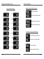
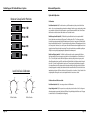
RadioPopper JrX Radio Wireless
Owners Manual
Table of Contents
RadioPopper is owned and manufactured by Leap Devices, LLC
in Phoenix Arizona. This product was designed, produced, and
manufactured in the USA.
FCC STATEMENT
This equipment has been tested and found to comply with the limits for a class B digital
device, pursuant to part 15 of the FCC Rules. These limits are designed to provide reasonable protection against harmful interference in a residential installation. This equipment
generates, uses and can radiate radio frequency energy and if not installed and used in
accordance with the instructions, may cause harmful interference to radio communications.
However, there is no guarantee that interference will not occur in a particular installation.
If this equipment does cause harmful interference to radio or television reception, which
can be determined by turning the equipment off and on, the user is encouraged to try to
correct the interference by one or more of the following measures:
* Reorient or relocate the receiving antenna.
* Increase the separation between the equipment and receiver.
* Connect the equipment into an outlet on a circuit different from that to which the receiver
is connected.
* Consult the dealer or an experienced radio/TV technician for help.
This equipment has been verified to comply with the limits for a class B computing device,
pursuant to FCC Rules. Operation with non-approved equipment is likely to result in interference to radio and TV reception.
The user is cautioned that changes and modifications made to the equipment without the
approval of manufacturer could void the user’s authority to operate this equipment.
FCC ID: V4TJRTX304
This device complies with Part 15 of the FCC Rules.
Operation is subject to the following two conditions:
IMPORTANT NOTE:
To comply with FCC RF exposure compliance requirements,
the following antenna installation and device operating
configurations must be satisfied - This device and its
antenna(s) must not be co-located or operating in
conjunction with any other antenna or transmitter.
PRODUCT PATENTS PENDING
Introduction . . . . . . . . . . . . . . . . . . . . . . . . . . . . . . . . . . . . . . . . . . . . . . . . . . . . .
4
Specifications and Warnings . . . . . . . . . . . . . . . . . . . . . . . . . . . . . . . . . . . . . . .
6
Parts Descriptions . . . . . . . . . . . . . . . . . . . . . . . . . . . . . . . . . . . . . . . . . . . . . . . .
8
Installation . . . . . . . . . . . . . . . . . . . . . . . . . . . . . . . . . . . . . . . . . . . . . . . . . . . . .
10
Control Switch Reference . . . . . . . . . . . . . . . . . . . . . . . . . . . . . . . . . . . . . . . . . .
12
Advanced Operation . . . . . . . . . . . . . . . . . . . . . . . . . . . . . . . . . . . . . . . . . . . . . .
15
EZset Operation . . . . . . . . . . . . . . . . . . . . . . . . . . . . . . . . . . . . . . . . . . . . . . . . . .
17
Limited Warranty . . . . . . . . . . . . . . . . . . . . . . . . . . . . . . . . . . . . . . . . . . . . . . . .
19
(1) This device may not cause harmful interference and
(2) this device must accept any interference received,
including interference that may cause undesired operation.
Copyright 2007-2009, Leap Devices LLC, All Rights Reserved
Leap Devices LLC, 4910 E. Elliot Rd. Suite #100, Phoenix, AZ 85044
Page 2
RadioPopper JrX User Manual - Rev 1.02
JrX Transmitter Firmware Version 3.07
JrX Receiver Firmware Version 3.03
Page 3
RadioPopper JrX Radio Wireless System
Introduction
Introduction
Thank you for your purchase of the RadioPopper JrX wireless radio
system. We hope you’ll find this system to be a valuable tool in your
creative lighting, giving you flexibility and control never before
possible.
The RadioPopper JrX system is a high quality and highly reliable radio
triggering system. The JrX provides long range triggering of lighting
equipment, as well as integration and compatibility with RadioPopper
PX units. The JrX is also forward compatible with upcoming “X System”
devices.
Please read this short manual entirely before installing or operating
your RadioPopper JrX wireless system. Your JrX units ship in default
configuration providing the most intuative “out of the box” experience.
The units are pre-set to the most commonly used settings. This manual
will help you use the more advanced optional features of the JrX units
when necessary.
If you have any troubles along the way, feel free to call or email.
[email protected]
Page 4
Page 5
RadioPopper JrX Radio Wireless System
Specifications and Warnings
Compatible Hardware:
WARNING!!! WARNING!!! WARNING!!!!
The JrX System has been tested and found to be compatible with the following flash hardware.
Transmitter:
May be used with any camera with a standard hotshoe mount. May also be used via an external PC Sync cable appropriate to your particular brand of camera. The external sync port on the transmitter accepts a standard 3.5mm mono
or stereo male plug. The sync voltage is approximately 3 volts - safe for use with all current model cameras.
Receiver General Triggering:
JrX Receiver will trigger most lighting devices via the standard sync connector. The sync connector accepts a standard
3.5mm mono or stereo male plug.
Receiver “Studio” Data Port Triggering:
JrX Receiver “Studio” version enables the ‘telephone’ style Data Port. This port is compatible with all current model
studio ligthing system from Alien Bees, White Lightning, and Zeus.
PX Triggering / Receiving:
Note: Triggering PX Receiver units with JrX Transmitter units requires firmware version 6-04 or later on the PX Receiver.
If a firmware upgrade is required on your PX Receiver, contact us for more information.
The JrX Transmitter will trigger PX Receiver units (firmware 6-04 or later) tuned to the same radio channel. The PX
Transmitter (all firmware versions) will trigger JrX Receiver units tuned to the same radio channel.
Specifications:
Transmitter Specifications
Dimensions : 1.75” x 2.25” x 1.25” (45mm x 57mm x 30mm)
Weight: 1.7 ounces / 48 grams (Including battery and antenna during normal operation)
Battery: One “CR123” Size Battery, 3.0 volt, including rechargeable and non-rechargeable.
Battery Life: Approx 50 Hours total power-on time per battery.
Radio Frequency: 902-928 Mhz, ISM Band
Radio Range: 300 ft to 1750 ft depending on conditions and environment.
Maximum Syn Speed: 1/250 Shutter Speed for cameras having leaf shutters.
PLEASE read this section in detail for important warnings and notices.
USE ONLY THE SUPPLIED TRANSMITTER ANTENNA!
Using any antenna other than the one supplied for use with your JrX Transmitter is a violation of Federal Law and may actually
cause damage to the radio inside the transmitter. This will also promptly void your warranty. Your JrX Transmitter has been
carefully tuned to broadcast the maximum signal strength allowable by law. Altering the antenna characteristics is more
likely to “de-tune” or degrade performance than to improve it.
INSERT THE BATTERY IN THE CORRECT DIRECTION!
Inserting the batteries “backwards” could possibly damage the electronic components inside JrX Transmitter and JrX Receiver
units. The little “bump” on the CR123 points down when inserting. A graphic is provided at the base of the battery holder.
Further, you should observe for the Green Power LED light after you insert the battery - indicating proper insertion.
DO NOT REMOVE OR TAMPER WITH THE CIRCUIT BOARD!
Some of the components inside your JrX Transmitters and JrX Receivers are especially susceptible to electrostatic shock
(they’re easily ‘zapped’ by static electricity) - just touching them could damage them. Your circuit board is grounded to the
case - as long as it’s not removed everything is safe. Removing or tampering with your circuit board will promptly void your
warranty.
YOUR POPPERS CAN’T SWIM!! KEEP THEM DRY!!
JrX units are not waterproof. Don’t use them outside in the rain, to photograph objects under water, or in any other environment that may allow water to enter the physical enclosure or battery area.
If you dunk them, it may be too late. Should you do manage to expose a RadioPopper to anything wet, remove the battery as
quickly as possible and allow it 24 hours to dry. You may find it has come back to life. Allowing anything wet inside the case
of your JrX Transmitter or JrX Receiver will promptly void the warranty.
CONTACT US IF YOU GET CONFUSED!
You’re a valued customer and we really do care about you. (And not in that automated “your call is very important to us
but we’re going to leave you on hold for an hour anyway” customer service recording sort of way). Seriously, if you have
questions, we’re going to do everything possible to take care of you as quickly and as personally as possible. The phone
number is on our website and you can always email us at [email protected]
Receiver Specifications
Dimensions : 4.0” x 1.75” x 1.2” (100mm x 45mm x 30mm)
Weight: 1.9 ounces / 53 grams (Including battery and antenna during normal operation)
Battery: One “CR123” Size Battery, 3.0 volt, including rechargeable and non-rechargeable.
Battery Life: Approx 50 Hours total power-on time per battery.
Radio Frequency: 902-928 Mhz, ISM Band
Radio Range: 300 ft to 1750 ft depending on conditions and environment.
Page 6
Page 7
RadioPopper JrX Radio Wireless System
Page 8
Parts Description
Page 9
RadioPopper JrX Radio Wireless System
Installation
Installation & Basic Operation: RadioPopper JrX Transmitter
Installation & Basic Operation: RadioPopper JrX Receiver
1) Remove the battery compartment door on the top side of the unit. Insert a single CR123 Lithium battery. Take
care to follow the direction / polarity indications printed inside the battery clip. Secure the battery by pressing it
straight down into the clip - it will click into place. Replace the battery compartment door.
1) Remove the battery compartment door on the top side of the unit. Insert a single CR123 Lithium battery. Take care
to follow the direction / polarity indications printed inside the battery clip. Secure the battery by pressing it straight
down into the clip - it will click into place. Replace the battery compartment door.
2) To power on the JrX Transmitter, press and hold the power button for approximately two seconds. The Power LED
will light to indicate the unit is powered on and operational.
2) Connect the JrX Receiver to your lighting equipment - a studio strobe unit, power pack, mono light, or battery
powered strobe unit. Connect the appropriate cable between the Sync Port on the side of the JrX Receiver to the
trigger port or hot shoe connector of your lighting equipment. The cable that inserts into the JrX Receiver is a male
1/8” mini-phono plug. The sync port accepts mono or stereo type connectors. If you are using White Lightning,
Alien Bees, or Zeus brand studio lights, you may optionally attach the light via the RJ-11 / Telephone style Data Port
connector provided on the JrX Receiver. NOTE: The Data Port connector is only enabled in the “Studio” version of the JrX
Receiver. This port is NOT enabled in the “Basic” version of the JrX Receiver. For more information about the use of the
Data Port to control compatible studio lights, please refer to the section on page 12.
3) You may trigger the JrX Transmitter in one of two ways. You may either slide the transmitter onto your camera’s
hot shoe connector, in which case the JrX Transmitter will activate and broadcast a trigger signal each time you
activate your camera’s shutter. You may optionally connect a sync cord to the sync port provided on the side of the JrX
Transmitter. Activating this sync cord will also cause your JrX Transmitter to activate and broadcast a trigger signal.
4) Configure the option switches as required to set your desired channel and options. Please refer to pages 13 and 15
for instructions and reference as to the proper settings of the option switches.
5) On the JrX Receiver STUDIO only, you may adjust the light intensity level of up to three groups of remote lighting
devices using the group adjustment dials on the side of the JrX Transmitter unit. When installed on a camera hot shoe
with the Power button and Power LED facing toward you, the closest dial to you is Group 1, the middle dial is Group
2, and the furthest dial from you is Group 3. Turn the dials counter-clockwise (“away from you”) to increase lighting
intensity level, turn them clockwise (“toward you”) to decrease the lighting intensity level. Please refer to pages 14
and 17 for instructions and details regarding the use of the group adjustment dials.
6) You may tap the Power button one time to send a test shot and to perform a battery level check. The Power LED
will strobe at one of three speeds, faster to slower, depending on current battery level. A slow constantly blinking LED
indicates low battery and you have approximately one to two hours of battery life remaining.
7) Press and hold the Power button for approximately two seconds to power off the unit. When the unit powers off
the Power LED will go dark.
NOTE: If using the Data Port Connector, it is NOT necessary to connect an additional cable to the Sync Port to achieve
activation of the attached light. However, some lights provide an optical slave triggering function where they will
activate when observing light from other sources. When using a light with an optical slave, connected by the Data Port
connector, and being used in conjunction with PX units include ETTL or iTTL type communications, it is important to
disable the optical triggering function by placing a plug or connector in the sync port of the light itself.
3) To power on the JrX Receiver, press and hold the power button for approximately two seconds. The Power LED will
light to indicate the unit is powered on and operational. The JrX Receiver will perform a self-test and will activate the
attached light one time. If a JrX Receiver “Studio” unit is attached to compatible lighting via the Data Port, you will see
the modeling lamp of that light cycle up and down during this self test. The self test is complete in approximately two
seconds. The unit then enters normal operation.
VERY IMPORTANT: When using a JrX Receiver Studio to control the levels of studio lights using the Data Port, the
JrX Receiver Studio must be connected to the light BEFORE turning on the JrX Receiver Studio. The controlled light
will “see” the JrX Receiver Studio during the self test. If not powered on while attached to the controlled light, the
controlled light may not respond level adjustments from the JrX Receiver Studio.
4) Configure the radio channel, group setting, and other settings using the Option Switches. Please refer to page 12
for details as to the settings of these switches.
5) Tap the Power button one time to cause the attached light to emit a test fire.
6) To power off the unit, press and hole the Power button for approximately two seconds until the Power LED goes
dark.
Page 10
Page 11
RadioPopper JrX Radio Wireless System
Control Switch Reference
Receiver Function Switch Positions
Channel Switch Positions
Error Checking Disabled
ON
1
9
ON
2
10
ON
1
2
3
4
5
6
7
8
1
2
3
4
5
6
7
8
2
3
4
5
6
7
8
3
11
ON
1
2
3
4
5
6
7
8
4
12
ON
1
5
13
ON
ON
ON
ON
ON
1
2
3
4
5
6
7
8
1
2
3
4
5
6
7
8
1
2
3
4
5
6
7
8
1
2
3
4
5
6
7
8
1
2
3
4
5
6
7
8
Error Checking Enabled (Default)
AB Model Lamp Track Enabled
AB Model Lamp Track Disabled
Transmitter Function Switch Positions
1
2
3
4
5
6
7
8
Disable Group at Low Dial Position
6
14
ON
7
15
ON
8
8
8
16
ON
ON
1
2
3
4
5
6
7
8
1
2
3
4
5
6
7
ON
ON
1
2
3
4
5
6
7
1
2
3
4
5
6
7
8
1
2
3
4
5
6
7
8
All Groups Fire at Low Dial Position
Disable Level Updates
1
2
3
4
5
6
7
8
Enabled Level Updates (Default)
Page 12
Page 13
RadioPopper JrX Radio Wireless System
Advanced Operation
Option Switch Operation
Receiver Group Switch Positions
JrX Transmitter
Radio Channel (switches 1-4) - The radio channel on your JrX Transmitter is set by the positions of the first four
switches. It is not so much important that you know what combination of switches creates a given channel, just make
sure to match the on/off pattern of the first four switches on your JrX Transmitter and JrX Receivers. This will ensure
that all units are on the same channel. Note that there are 16 total radio channels.
Disable Group at Low Dial (switch 5) – The Disable Group at Low Dial switch is used in conjunction with JrX
Receiver Studio units connected using the EZset system. The default position, OFF or “0”, will cause any strobes to
fire at their lowest output power when the JrX Transmitter’s power dial is set to its lowest position. When the Disable
Group at Low Dial switch is turned ON, or “1”, any attached strobes will not fire when a JrX Transmitter power dial is set
to its lowest position. In this mode, as soon as the power dial on the JrX Transmitter is turned slightly above its lowest
setting, the strobe will begin to fire at its lowest setting. This mode is beneficial when you would like to quickly turn
off lights on a certain group by simply turning the adjustment dial to minimum power.
Disable Level Updates (switch 6) – The Disable Level Updates switch is used in conjunction with JrX Receiver
Studio units using the EZset system to remote control power levels of various lighting devices. The default value of
OFF, or “0”, has Level Updates enabled. While Level Updates are enabled, any changes made on the group control
dials will be immediately sent to any JrX Receiver Studio units. When the Disable Level Updates switched is changed
to the ON or “1” position, Level Updates will no longer be sent. This mode may be beneficial when a photographer
is shooting with an assistant. The assistant may have level updates disabled yet still be able to fire at the levels that
the main photographer is controlling. Note that when this switch is turned from ON to OFF, the levels of the dials are
immediately read and sent to JrX Receiver Studio units. It is thus possible to also use this as a “safety” switch to lock in
set lighting while still being able to send occasional updates if minor level corrections are desired.
Level Dial Scale Calibration
1/8
1/4
1/2
1/8
1/16
1/32
1/4
JrX Receiver Basic and JrX Receiver Studio
Radio Channel (switches 1-4) – Same setup procedure as the JrX Transmitter
1/64
1/2
1/16
1/1
1/32
EZset Studio
Page 14
1/1
1/128
Group Setting (switches 5-6) – Groups can be set according to the positions of switches 5 and 6. See diagram to
determine appropriate group setting. Note that the “No Group” setting will simply take the Receiver out of all groups
to enable the strobe to be set manually, while still triggering.
EZset Strobe
Page 15
RadioPopper JrX Radio Wireless System
Disable Error Checking (switch 7) – The JrX Receiver performs error checking on all radio messages. This ensures
that background radio signals do not cause the JrX to false trigger. In nearly all situations error checking should remain
enabled (switch 7 is OFF or “0”) which is the default setting. There are two situations where it may be desirable to
disable error checking (switch 7 on ON or “1”).
Operation at the edge of radio range: The radio signal is a stream of digital 1’s and 0’s. Near the edge of range,
there may be some errors in the incoming radio transmission. It is likely that enough of the signal has been received
correctly for the JrX to operate, yet a single bit error would cause error checking to disregard the message. By disabling
error checking, the receiver may still activate even if the signal has some bit errors.
Operation with certain Canon bodies and certain lights at 1/250 shutter speed: RadioPopper has observed that a small
number of Canon camera bodies when triggering a small number of studio strobes at the max x-sync of 1/250 can
produce shots with a very faint, almost unnoticeable shadow from the camera shutter on the bottom of the frame. By
disabling error checking, the remote light will activate more quickly and this effect will be eliminated.
Note that a negative effect of disabling error checking is that the JrX Receiver may occasionally false trigger due to
background radio noise. As false triggering is a “negative” effect, error checking should always be enabled except in
the two circumstances indicated.
Modeling Lamp Tracking (switch 8) – (JrX Receiver STUDIO only) – The the JrX Receiver is attached to an Alien
Bees, White Lightning or Zeus strobe using the EZset function, a user may or may not want the strobe’s molding lamp
to track with the power adjustment. The default position of switch 8 is ON or “1” in which modeling lamp tracking is
enabled. Changing to the OFF or “0” position will turn off tracking. NOTE: When turning off tracking is desired, you
must also turn off tracking on the strobe control panel. You may observe that the modeling lamp still slightly changes
with tracking disabled which is normal and is an effect due to electrical coupling inside the controlled light.
IMPORTANT NOTE: If Modeling Lamp Tracking is desired, switch 8 must be turned ON. Additionally, you must set (turn
“on”) the model lamp tracking button on the rear controls on the light itself.
Battery Level Check / Alarm
Both the JrX Transmitter and Receiver units include a battery level indicator and low battery level alarm. The supplied
battery should provide 40-50 hours of continual “on” time regardless of the number of shots taken. When the JrX units
are turned on, or when the power button is tapped one time, the unit will indicate the battery level by strobing the
green power light. The power light will strobe fast for full battery, half speed for mid-battery and very slowly for a
low-battery. Approximately 2 hours before batteries are completely dead, the power light will begin to blink slowly.
During this blinking the units will still operate normally at full speed and full power with no noticeable loss of range,
however, it is recommended to replace the battery as soon as possible.
Page 16
EZset Operation
EZset Operation (JrX Receiver Studio Only)
EZset Studio – EZset Studio enables the ability to adjust the power levels of Alien Bees, White Lightning and Zues
brand lights from a JrX (or PX) Transmitter. After setting the appropriate option switches (see option switches section),
the three dials on the side of a JrX transmitter can control the output power of up to three groups of lights. Note that
turning the dial of the JrX transmitter is directly proportional to adjusting the power slider on the back of the light. For
example, a half turn of the dial is the same as putting the light’s slider half-way to full.
To properly set up the EZset Studio system with a JrX Receiver Studio, please follow the correct install procedure.
1. Ensure that the JrX Receiver Studio and the studio light are both turned OFF.
2. Attach the JrX Receiver to the studio light with the supplied “telephone” data cable.
3. Disable the optical slave function of the light by inserting the supplied 3.5mm plug into the light’s sync port.
4. Power on the studio light.
5. Power on the JrX Receiver. JrX Receiver must be powered on after the studio light to enable proper tracking.
6. When the JrX Receiver is turned on, the modeling lamp should quickly ramp up then down and then trigger once.
EZset Strobe – EZset Strobe enables the ability to adjust the power levels of TTL / “Dedicated” flashes compatible with
Canon or Nikon Cameras. The RPcube Canon is required for Canon compatible strobes and the RPcube Nikon is required
for Nikon compatible strobes. Use the supplied 3.5mm stereo cable to connect the sync connector of the JrX Receiver
to the matching 3.5mm jack provided on the RPcube.
After setting the appropriate option switches (see option switches section), the three dials on the side of a JrX
transmitter can control the output power of up to three groups of strobes. Note that EZset Strobe can control roughly 8
stops of flash power. Each 1/8th turn of the dial on the JrX Transmitter will represent 1 stop of flash power. Note that
due to the wide variety of flashes available, each 1/8th turn may be slightly greater or slightly less than 1 stop of flash
power.
The EZset Strobe function has been approximately calibrated for stop accurate light output from a Nikon SB-800 Speed
Light. Though smaller or larger strobes may put out more or less power, a 1/8 turn of the dial will still roughly equal
one stop of power adjustment regardless of the make, model, or size of strobe used.
NOTE: It is possible to mix both EZset Studio and EZset Strobe functionality within the same lighting system. For
example, placing studio strobes (EZset Studio) on one group and placing hand held strobes (EZset Strobe) on
another group. It is also possible to mix the above functionality with proper ETTL/iTTL functionality when used with
a RadioPopper PX Transmitter. The ETTL/iTTL pre-flash and calculations are all performed before activating lights
attached to JrX Receiver units, thus the lights attached to JrX Receiver units will not alter the ETTL/iTTL exposure. All
ETTL/iTTL groups, ratios, and power levels are maintained.
Page 17
RadioPopper JrX Radio Wireless System
Limited Warranty
LIMITED WARRANTY The Limited Warranty set forth below is given by Leap Devices LLC (hereafter “Leap”) in the United States with respect to the RadioPopper JrX Transmitter
and / or RadioPopper JrX Receiver packaged with this Limited Warranty and identified by model number within this Limited Warranty (each a “Product”)
when purchased and used in the United States or in Canada.
This Limited Warranty is only effective upon presentation of this warranty card and proof of purchase.
A Product, when delivered to you in new condition in its original container at the point of it’s initial retail sale, is warranted against defects in materials
or workmanship as follows: for a period of one (1) year from the date of original purchase, defective parts or a defective Product returned to Leap or
its authorized service providers, and proven to be defective upon inspection, will be repaired with new or comparable rebuilt parts or exchanged for a
refurbished Product, as determined by Leap or the authorized service provider, in their sole discretion. Replaced parts and exchanged Products will become
the property of Leap.
When returning a Product for warranty service, the shipping charges must be prepaid and the Product should be shipped in its original container, or an
equivalent, properly packaged container to withstand the hazards of shipment and fully insured. A copy of this warranty card and proof of purchase should
be enclosed, as well as a description of the problem. Repairs will be made and the Product will be returned, shipped at NO CHARGE, within the country of
repair. The Product must be received for warranty service by Leap before the expiration of this Limited Warranty. This warranty only covers defective materials or workmanship encountered in normal use and service of a Product and does not apply in the following
cases:
(a) If a circuit board is removed from the plastic enclosure for any reason or if the original factory seal between the circuit board and plastic enclosure is
disturbed in any way. Tampering with or removing the circuit board from the enclosure VOIDs this warranty.
(b) Loss or damage due to neglect and/or abuse causing deterioration, mishandling, accident or failure to follow operating instructions including but not
limited to operation of a JrX Transmitter with no antenna attached, or operation with an antenna other than that provided with the product originally, or
inserting the batteries backward for any length of time.
(c) If a Product is defective as a result of leaking batteries or damage due to water or other liquid, or any environmental conditions.
(d) Defective materials or workmanship where the defect is due to a Product having been serviced or modified by other than Leap or a Leap authorized
service provider.
(e) Malfunction resulting from the use of accessories, attachments, supplies, parts or devices (including, without limitation, batteries) that do not conform
to Leap specifications.
(f) Damage resulting during shipment. (Claim must be presented to and examined by the shipper).
(g) Damage or service resulting from modifications or alternations to a Product in any way (including any alteration or removal if its serial number or
identification marks).
Canon is a registered trademark of Canon Inc. in the United States and may also be a registered trademark or trademark in other countries. ITTL stands for
Intelligent Through The Lens, the trade-marked name for Nikon’s exposure measurement system on SLR cameras. Nikon is a registered trademark of Nikon
Corporation. Alien Bees, White Lightning, and ZEUS are manufactured by Paul C. Buff, Inc.
NO IMPLIED WARRANTY, INCLUDING ANY IMPLIED WARRANTY OF MERCHANTABILITY OR FITNESS FOR A PARTICULAR PURPOSE, APPLIES TO A PRODUCT
AFTER THE APPLICABLE PERIOD OF THE EXPRESS LIMITED WARRANTY STATED ABOVE, AND NO OTHER EXPRESS WARRANTY OR GUARANTY, EXCEPT AS
MENTIONED ABOVE, GIVEN BY ANY PERSON OR ENTITY WITH RESPECT TO A PRODUCT SHALL BIND LEAP (SOME STATES AND PROVINCES DO NOT ALLOW
LIMITATIONS ON HOW LONG AN IMPLIED WARRANTY LASTS, SO THE ABOVE LIMITATION MAY NOT APPLY TO YOU). LEAP SHALL NOT BE LIABLE FOR LOSS OF
REVENUES OR PROFITS, INCONVENIENCE, EXPENSE FOR SUBSTITUTE EQUIPMENT OR SERVICE, STORAGE CHARGES, LOSS OR CORRUPTION OF DATA, OR ANY
OTHER SPECIAL, INCIDENTAL OR CONSEQUENTIAL DAMAGES (INCLUDING, WITHOUT LIMITATION, ANY LOSS OF FILM OR DIGITAL IMAGE FILES) CAUSED BY THE
USE OR MISUSES OF, OR INABILITY TO USE, A PRODUCT, REGARDLESS OF THE LEGAL THEORY ON WHICH THE CLAIM IS BASED, AND EVEN IF LEAP HAS BEEN
ADVISED OF THE POSSIBILITY OF SUCH DAMAGES. IN NO EVENT SHALL RECOVERY OF ANY KIND AGAINST LEAP BE GREATER IN AMOUNT THAN THE PURCHASE
PRICE OF THE PRODUCT SOLD BY LEAP AND CAUSING THE ALLGED DAMAGE. WITHOUT LIMITING THE FOREGOING, YOU ASSUME ALL RISK AND LIABILITY
FOR LOSS, DAMAGE OR INJURY TO YOU AND YOUR PROPERTY AND TO OTHERS AND THEIR PROPERTY ARISING OUT OF THE USE OR MISUSE OF, OR INABILITY
TO USE, THE PRODUCT NOT CAUSED SOLELY AND DIRECTLY BY THE NEGLIGENCE OF LEAP (SOME STATES AND PROVINCES DO NOT ALLOW THE EXCLUSION OR
LIMITATION OF INCIDENTAL OR CONSEQUENTIAL DAMAGES, SO THE ABOVE EXCLUSION OR LIMITATION MAY NOT APPLY TO YOU). THIS LIMITED WARRANTY
SHALL NOT EXTEND TO ANYONE OTHER THAN THE ORIGINAL PURCHASER OF A PRODUCT, OR THE PERSON FOR WHOM IT WAS PURCHASED AS A GIFT AND
STATES YOUR EXCLUSIVE REMEDY.
RadioPopper and Leap Devices, LLC does not represent or otherwise endorse the 3rd party companies or products discussed in this manual.
Leap Devices LLC, 4910 E. Elliot Rd. #100, Phoenix, AZ 85044
RadioPopper is manufactured in the USA by Leap Devices, LLC. RadioPopper and EZset are trademarks of Leap Devices, LLC.
All other product and brand names are trademarks of their respective owner.
Page 18
Page 19
Copyright 2007-2009, Leap Devices LLC, All Rights Reserved