1
Everywhere you imagine.
bit (W43) and Timer LC. The frequency (F) of the LCD clock used in the sample software is
64Hz, using the bit 4 of Timer3 as the count source. The formula is as shown below:
F = T34 ×
1
1
×
LC + 1 2
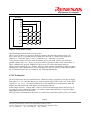
The LCD power input pins (VLC1~VLC3) are used as pins SEG0~SEG2. Hence, internal power
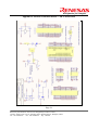
(VDD) is used for the LCD power and internal dividing resistors are used. The circuitry for external
dividing resistors is available on the evaluation board when VLC1~VLC3 pin function are to be used.
Refer to the 4559 Group datasheet for more information on LCD Function.
4.3 Transmission Format
The infra-red remote control signal generated uses a carrier frequency of 38 KHz, with 1/3 duty cycle.
The remote control signal is generated using Timer1 and Timer 2. The generated signal is output from
C/CNTR pin. There is only one frame of signal transmitted with a valid key pressed.
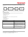
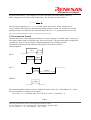
The transmission format for the Transmission Program is described as follows:
Header/Separator:
9ms
4.5ms
Bit “0”:
0.56ms
0.56ms
Bit “1”:
0.56ms
1.69ms
END bit:
0.56ms
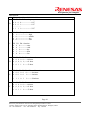
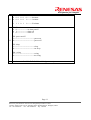
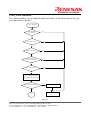
The transmission data consists of 9 bytes. Each byte consists of byte “H” (4-bit) and byte “L” (4-bit).
The representations of each byte are as follows:
User code(A)+ Function code(B+C+D+E+F+G+H)+Checksum(I)
Page 9
Renesas System Solution Asia Pte.Ltd Shanghai Pepresenative Office
Unit 207 AZIA Center, No133 Yincheng Rd(n), Pudong District, Shanghai, China
Tel: 021-68880556
Fax: 021-68880559
Zip: 200120