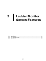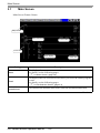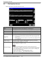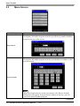
1
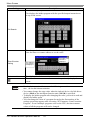
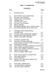
Mitsubishi Electric Q Series PLC Ladder Monitor Operation Manual Introduction Thank you for purchasing the PLC Ladder Monitor Add-on Kit for the Mitsubishi Electric Corporation Q Series. This manual explains the operations for monitoring the PLC ladder programs and device addresses using the GP3000 Series Programmable Display manufactured by Pro-face (Digital Electronics Corporation of Japan.) Please read the manual thoroughly for proper use of this product. Be sure the manual is always available where this product is used. Note (1) All programs and manuals of “PLC Ladder Monitor Add-on Kit for Mitsubishi Electric Corporation’s Q Series” (called the product, hereafter) are copyright of Digital Electronics Corporation of Japan and Digital Electronics Corporation of Japan shall grant the users the license as described in “Software License”. Any conduct violating the “Software License” is prohibited by the laws and regulations in Japan and other countries. (2) The manual has been prepared for additional assurance. Should you have any concerns, please contact Digital Electronics Corporation of Japan’s “Support Line”. (3) Notwithstanding the previous paragraph, Digital Electronics Corporation of Japan shall not be responsible for any damage or other loss, or any claims from a third party as a result of using this product. (4) Some parts and product software may differ from the description in the manual due to product improvements. For the latest descriptions, see also the separate document and on-line information. (5) The product may record/display some information containing intangible or intellectual property belonging to Digital Electronics Corporation of Japan. This shall not grant the users or third parties a guarantee or license for these properties of Digital Electronics Corporation of Japan. Digital Electronics Corporation of Japan shall not be held responsible for any problems arising from the recording/displaying of a third party’s intellectual property using this product. © Copyright 2007 Digital Electronics Corporation of Japan. All rights reserved. All product names described herein are trademarks or registered trademarks of the respective owners. PLC Ladder Monitor Operation Manual 1 Manual Description This manual provides following cautions for proper use of the PLC Ladder Monitor Add-on Kit for the Mitsubishi Electric Corporation Q Series. The cautions described herein contain important safety informaiton. The following table shows the symbols and what they mean. Symbol Meaning Failure to follow the instructions on the display may result in adverse events such as device errors or data loss. Important points for use. * The footnotes contain an explanation of the annotated words. ) Related reference pages are provided. PLC Programmable Logic Controller. Package Content Package Content CD-ROM: 1 User registry FAX sheet: 1 for Japanese/ English each Serial barcode sticker: 1 KEYCODE sticker 1 (Placed on the CD case) PLC Ladder Monitor Operation Manual 2 PLC Ladder Monitor Operation Manual 3 Table of Contents Introduction ............................................................................................................................................ 1 Manual Description ................................................................................................................................ 2 Package Content .................................................................................................................................... 2 Table of Contents ................................................................................................................................... 4 Chapter 1 Summary 1.1 Ladder Monitor ......................................................................................................................... 1-2 1.2 Supported Models .................................................................................................................... 1-3 1.3 Devices that are able to displayed and searched by Ladder Monitor ...................................... 1-5 1.4 System Configuration ............................................................................................................... 1-7 1.5 Installation Procedure .............................................................................................................. 1-9 Chapter 2 Using the Ladder Monitor 2.1 Settings Menu .......................................................................................................................... 2-2 2.2 Monitoring the PLC Ladder Programs on a Display ................................................................. 2-3 2.3 2.4 2.5 Chapter 3 2.2.1 Details ..................................................................................................................... 2-3 2.2.2 Setup Procedure ..................................................................................................... 2-4 Displaying Ladder Programs in Alarm History View ................................................................ 2-9 2.3.1 Details ..................................................................................................................... 2-9 2.3.2 Setup Procedure ..................................................................................................... 2-9 Printing the Ladder Monitor View from a Display ................................................................... 2-11 2.4.1 Details ................................................................................................................... 2-11 2.4.2 Setup Procedure ................................................................................................... 2-11 Capturing and Saving the Ladder Monitor View on a CF Card .............................................. 2-12 2.5.1 Details ................................................................................................................... 2-12 2.5.2 Setup Procedure ................................................................................................... 2-12 Ladder Monitor Screen Features 3.1 Main Screen ............................................................................................................................. 3-2 3.2 File Selection Screen ............................................................................................................... 3-4 3.3 Menu Screen ............................................................................................................................ 3-6 Chapter 4 Restrictions PLC Ladder Monitor Operation Manual 4 1 Summary 1.1 Ladder Monitor ................................................................................................1-2 1.2 Supported Models ...........................................................................................1-3 1.3 Devices that are able to displayed and searched by Ladder Monitor .............1-5 1.4 System Configuration......................................................................................1-7 1.5 Installation Procedure .....................................................................................1-9 1-1 Ladder Monitor 1.1 Ladder Monitor The ladder monitor is a feature that reads and monitors the PLC (Mitsubishi Electric Corporation PLC Q series) ladder programs on a display screen. It monitors the ladder programs online without stopping other features. Production Input Screen 7 8 9 4 5 6 1 2 3 0 . Ladder Monitor You can use the ladder monitor feature to do the following: • Monitor the PLC ladder program over the internet Displays the contact, coil and output instruction in bold/color while they are energized. Display the I/O comments in the ladder program • Specify and display the ladder program you wish to check Display the ladder monitor simultaneously with the alarm display Search for a step number or a device address • Save the desired ladder program view Capture and save the image on a CF Card Print the desired ladder program view • Edit timer and counter instruction values over the internet • See the following pages for devices that can be displayed and monitored by the ladder monitor. ) “1.3 Devices that are able to displayed and searched by Ladder Monitor” (page 1-5) • The ladder monitor mode calls the device monitor feature. The device monitor feature allows you to see the device you are using and change the values. ) “3.3 Menu Screen” (page 3-6) See: GP-Pro EX Reference Manual PLC Ladder Monitor Operation Manual 1-2 Supported Models 1.2 Supported Models Supporting Connected Device Maker Series Name High Performance Model Mitsubishi Electric Corporation Q series Universal Model CPU Q02CPU Q02HCPU Q06HCPU Q12HCPU Q25HCPU Q00UJCPU Q00UCPU Q01UCPU Q02UCPU Q03UDCPU Q04UDHCPU Q06UDHCPU Q10UDHCPU Q13UDHCPU Q20UDHCPU Q26UDHCPU Device PLC Names on GP-Pro EX Link I/F (Version)*2 Mitsubishi Electric Corporation Q series CPU Direct RS-232C CPU direct (V1.16.10 or later) Mitsubishi Electric QJ71E71 Corporation Q/QnA Ethernet QJ71E71-B2 QJ71E71-B5 (UDP/IP Connection) Series Ethernet QJ71E71-100 (V1.12.04 or later) Communication method*1 CPU Direct RS-232C Mitsubishi Electric Corporation Q series CPU direct (V1.16.10 or later) RS-232C Mitsubishi Electric Corporation Q series CPU direct (V1.16.10 or later) *3 Q03UDECPU Q04UDEHCPU Q06UDEHCPU Q10UDEHCPU Q13UDEHCPU Q20UDEHCPU Q26UDEHCPU RS-232C port on High Performance and Universal Model Q CPU*4 *3 *1 Communication mode changes according to type of link unit, cables used, etc. For details, see the relevant driver manuals. *2 The driver version can be checked by viewing [Peripheral List] in the [System Settings] window on the GPPro EX, or [Driver Version] on [Offline Home] on the display. *3 Supported instructions are GX-Developer Ver8.74C or earlier programming tool by Mitsubishi Electric Corporation. *4 To communicate with QUDECPU, set Multi CPU System trough QCPU's RS-232C port. (The supported QCPU are the CPU except for QUDECPU listed above.) Communicate the display and the QCPU by CPU Direct. • If the driver for “Mitsubishi Electric Corporation Q/QnA Series Ethernet” is not displayed, download the update module from the Pro-face support site “Otasuke Pro!”. PLC Ladder Monitor Operation Manual 1-3 Supported Models Relevant Display For displays that support the ladder monitor, see the Pro-face support site “Otasuke Pro!” URL http://www.pro-face.com/otasuke/ Screen Creation Software by Pro-face (Digital Electronics Corporation of Japan) GP-Pro EX Ver.2.00 or later Mitsubishi Electric Corporation Programming Tools MELSOFT GX Series GX Developer • For the programming tool versions that support the ladder monitor, see the Pro-face support site “Otasuke Pro!”. Some versions may not be able to display the ladder programs. • For the instructions that the ladder monitor can monitor, see the programming tools manual for the relevant version. PLC Ladder Monitor Operation Manual 1-4 Devices that are able to displayed and searched by Ladder Monitor 1.3 Devices that are able to displayed and searched by Ladder Monitor The devices that are able to displayed and searched are as below. Device Input Relay Output Relay Internal Relay Special Relay Latch Relay Annunciator Edge Relay Step Relay Link Relay Special Link Relay Timer (contact) Timer (coil) Timer (Current Value) Retentive Timer (contact) Retentive Timer (coil) Retentive Timer (Current value) Counter (Contact) Counter (coil) Counter (Current Value) Data register Extended data register Special register Link register Extended link register Special link register File register Direct input device Direct output device Function input Function output Function register Displayed Device Displayed Name Objects GP-Pro Ladder Comment/ EX Monitor Monitor O X X O Y Y O M M O SM SM O L L O F F O V V X S S O B B O SB SB O TS O TC T O TN O SS O SC ST O SN CS CC CN D D SD W W SW R ZR 0-31R - C D D SD W W SW R ZR 0-31R DX DY FX FY FD Searched Objects Coil Bit Adress Word Adress O O X O O X O O X O O X O O X O O X X O X X X X O O X O O X O O X O O X X X O O O X O O X X X O O O O X O O O X O X X O O O O O X X X X O O O O O O O O X X X X O O O O O O O O O O O O O X X X X X X X X X X X X X X X X X X X X X X X (continued) PLC Ladder Monitor Operation Manual 1-5 Devices that are able to displayed and searched by Ladder Monitor Device Displayed Device Displayed Name Objects GP-Pro Ladder Comment/ EX Monitor Monitor Searched Objects Coil Index register or standard X X Z device register X X N Nesting X X P Pointer X X I Interrupt pointer X X BL SFC block device X X TR SFC transition device X X Jn\X Link input X X Jn\Y Link output X X Jn\B Link relay X X Jn\SB Link special relay X X Jn\W Link register X X Jn\SW Link special register Intelligent function module X X Un\G device Cyclic transmission area O O U3En- U3En\G device *1 Network No. specification X X J device I/O No. specification X X U device Macro instruction X X VD argument device X X Decimal constant(16 bits) K X X Decimal constant(32 bits) Hexadecimal constant X X (16 bits) H Hexadecimal constant X X (32 bits) Real number constant X X (Single-precision floatingpoint data:) E Real number constant X X (Double-precision floatingpoint data) X X Character string *1 This device can be used for Q Series CPU direct V1.02.00 or later. PLC Ladder Monitor Operation Manual 1-6 Bit Adress Word Adress X X X X X X X X X X X X X X X X X X X X X X X X X X O O X X X X X X X X X X X X X X X X X X X X System Configuration 1.4 System Configuration • For details on connecting the display and PLC, see “Mitsubishi Electric Corporation Q Series CPU Direct Driver” or “Mitsubishi Electric Corporation Q/QnA Series Ethernet Driver” in “GP-Pro EX Device Connection Manual”. • To monitor the Q/QnA Series with Ethernet Connection, you need to input the PC station number of the External Device that you want to monitor by GP-Pro EX. For the setting of PC station number, see “Mitsubishi Electric Corporation Q/ QnA Series Ethernet Driver” in “GP-Pro EX Device Connection Manual”. Communication Cable Connection The display and PLC are connected 1:1 with a communication cable. Display Production System Parameter Settings MELSEC Q series Cancel 7 8 9 4 5 6 1 2 3 0 . CLR DEL E N T COM1 RS232C port 8 round pins Connection cable Mitsubishi Q connection cable CA3-CBLQ-01 manufactured by Digital Electronics Corporation (5m) or RS-232C cable QC30R2 manufactured by Mitsubishi Electric Corporation (3m) or RS-232C cable DQCABR2V-H for MELSEC-Q CPU connection manufactured by Diatrend Corporation Ethernet Connection (UDP/IP Connection) • 1-to-1 connection Connected devices Display HUB PLC Ladder Monitor Operation Manual 1-7 System Configuration • 1-to-n connection (Access without network) Connected devices Display HUB Connected devices Up to 32 units (With a UDP/IP connection) • 1-to-n connection (Access via network) Display Connected devices Connected devices Ethernet Up to 32 units (With a UDP/IP connection) * Accessible only via a single-level hierarchical network • When communicating via a network, set the timeout to a value larger than that of the response monitoring time at the relay station. • n-to-1 connection MELSEC-Q Series : Up to 16 units * Connected devices Display Display HUB * When the “Open Setting” function is used for the connected device instead of the “Auto Open UDP Port” function, up to 16 displays can be connected. However, when the “Auto Open UDP Port” function is used for the connected device, there is no limit on the number of connected displays. • Use the connected units without changing their I/O numbers and station numbers. PLC Ladder Monitor Operation Manual 1-8 Installation Procedure 1.5 Installation Procedure ) “2.2.2 Setup Procedure” (page 2-4) 1 Install the add-on kit 2 Install the startup file onto a CF Card 3 Create a project file See: 4 Configure the device monitor ) “2.2.2 Setup Procedure” (page 2-4) 5 Transfer the project file with the device monitor settings to the display 6 ) “2.2.2 Setup Procedure” (page 2-4) GP-Pro EX Reference Manual See: GP-Pro EX Reference Manual Install the CF Card See: GP3000 Series Hardware Manual 7 Connect the display and PLC See: “Mitsubishi Electric Corporation Q Series CPU Direct Driver” or “Mitsubishi Electric Corporation Q/QnA Series Ethernet Driver” in “GP-Pro EX Device Connection Manual” 8 Start up the Ladder Monitor feature ) “2.2.2 Setup Procedure” (page 2-4) • GP-Pro EX Manual and the Hardware Manual are available for download on the Pro-face support site “Otasuke Pro!” (http://www.pro-face.com/otasuke/). See the manual for GP-Pro EX Ver.2.00 or later. PLC Ladder Monitor Operation Manual 1-9 Installation Procedure PLC Ladder Monitor Operation Manual 1-10 2 Using the Ladder Monitor 2.1 Settings Menu .................................................................................................2-2 2.2 Monitoring the PLC Ladder Programs on a Display........................................2-3 2.3 Displaying Ladder Programs in Alarm History View........................................2-9 2.4 Printing the Ladder Monitor View from a Display .......................................... 2-11 2.5 Capturing and Saving the Ladder Monitor View on a CF Card .....................2-12 2-1 Settings Menu 2.1 Settings Menu Monitoring the PLC Ladder Programs on a Display ) “2.2.1 Details” (page 2-3) ) “2.2.2 Setup Procedure” (page 2-4) CF Card You can display the PLC ladder program on a display screen. Displaying the Relevant Ladder Programs Simultaneously from Alarm History Date 2003/12/13 Trig 20:14 2003/12/13 20:02 ACK Voltage Error 2003/12/13 19:30 Recov 20:08 Hot Pipe Voltage Error 2003/12/13 2003/12/13 Message Conveyor Stopped Hot Pipe 2003/12/13 20:00 ) “2.3.1 Details” (page 2-9) ) “2.3.2 Setup Procedure” (page 19:40 Voltage Error Ladder Monitor 2-9) You can display the device for which the alarm is sounding directly from the alarm history screen. Printing the Ladder Monitor Screen on a Display ) “2.4.1 Details” (page 2-11) ) “2.4.2 Setup Procedure” (page 2-11) You can output the Ladder Monitor screen from a printer connected to the display. Capturing and Saving the Ladder Monitor Screen on a Display onto a CF Card Snapshot Save CF Card ) “2.5.1 Details” (page 2-12) ) “2.5.2 Setup Procedure” (page 2-12) You can capture the displayed Ladder Monitor screen and save it to a CF Card. PLC Ladder Monitor Operation Manual 2-2 Monitoring the PLC Ladder Programs on a Display 2.2 Monitoring the PLC Ladder Programs on a Display 2.2.1 Details • See the following pages for the detailed settings. )Chapter3 "Ladder Monitor Screen Features" (page 3-1) With the Ladder Monitor you can remotely view, search, and edit the PLC ladder program as it appears on the HMI. CF Card • The CF Card must have 100 MB or more of free space. • See the following pages for the search feature. ) “3.3 Menu Screen” (page 3-6) PLC Ladder Monitor Operation Manual 2-3 Monitoring the PLC Ladder Programs on a Display 2.2.2 Setup Procedure 1 Install the Ladder Monitor CD-ROM onto a PC installed with GP-Pro EX. Run Setup.exe on the CD to launch the installer. Follow the installer instructions to install. • Your PC must have GP-Pro EX Ver.2.00 or later installed. For the OS, see the GP-Pro EX Reference Manual. 2 Install the startup file on a CF Card. Install the CF Card onto your PC. Designate the drive where the CF Card is located to automatically install the file. • To use this feature, the CF Card must have 100 MB or more of free space. 3 Create a project file. There are four ways to start the Ladder Monitor. To start the monitor without using the system menu, you must configure the settings for starting the Ladder Monitor in GP-Pro EX in advance. • System menu • Switch parts • LS area • System variables: #H_LadderMonitor (no cache) #H_LadderMonitorCache (with cache) • To start up using the system menu, see the following pages. )Setup Procedure8 “Start up the Ladder Monitor.” (page 2-8) PLC Ladder Monitor Operation Manual 2-4 Monitoring the PLC Ladder Programs on a Display Using a Switch to Start Up Production Input Screen 7 8 9 4 5 6 1 2 3 E N 0 . T Ladder Monitor 1) From the [Parts (P)] menu, point to [Switch Lamp (C)] and select [Special Switch (P)] or click . Click and drag to place a switch is placed on the screen. 2) Double-click the switch you placed and in [Special Action] select [Start monitor switch]. In [Action], select [Ladder Monitor] or [Ladder Monitor (Cache)]. • Ladder Monitor Reads the ladder programs from the PLC every time you click the switch. The real-time ladder program is always displayed but it may take time to update the program status. • Ladder Monitor (Cache) Reads the ladder programs saved on the CF Card when you click the switch, reducing the read time.To update the ladder programs on the CF Card, in [Main Screen] on the GP, select [Read]. ) “3.1 Main Screen” (page 3-2) PLC Ladder Monitor Operation Manual 2-5 Monitoring the PLC Ladder Programs on a Display • Read the cache from a CF Card Normally, every time you start the Ladder Monitor, it communicates with the PLC to read the ladder programs and it may take time to display the ladder programs. To improve the display update speed, the Ladder Monitor feature reads the PLC ladder programs onto the device CF Card (cache) first and then displays them. Reading to the CF Card (cache) If you change the ladder programs on the PLC after reading the PLC ladder programs to the display CF Card, read the ladder programs to the CF Card again. In [Main Screen] on the GP, select [Read]. ) “3.1 Main Screen” (page 3-2) • To speed up the comment file display speed, create the following folder on the CF Card to copy the project comment file (∗.WCD) created with the GXDeveloper programming tool by Mitsubishi Electric. This saves reading on the PLC and allows for faster reading. ) “3.2 File Selection Screen” (page 3-4) Q Series CPU direct : “PLCLDMON\MIT_QCPU” Q/QnA Series Ethernet : “PLCLDMON\MIT_QETH” 3) Select [Select Shape], [Color], [Label], and any other features you require and click OK. Using an LS Area Bit to Start Up 1) The Ladder Monitor starts up if you turn ON bits in the LS area. Configure the settings for turning ON the following bits using switch parts and D-scripts. 15 3 2 1 LS2078 Reserved Reserved 1: Starting up the Ladder Monitor Reserved 1: Reading the cache data Bit 1 Turn ON to start up the Ladder Monitor. Turn ON to start the Ladder Monitor and display the ladder programs cached on the CF Card. Bit 3 • If the programs are not cached in advance, the bit only triggers the same action as Bit 1 turning ON (starts up the Ladder Monitor). To update the ladder programs on the CF Card, in [Main Screen] on the GP, select [Read]. ) “3.1 Main Screen” (page 3-2) • Bits other than Bits 1 and 3 are reserved. Do not use them. PLC Ladder Monitor Operation Manual 2-6 Monitoring the PLC Ladder Programs on a Display 4 Register the device monitor feature. In GP-Pro EX, from [System Settings], point to [Display Unit] and select [Extended Settings]. Select the [Device Monitor] checkbox. • The device monitor screen uses a global display window. While the device monitor is displayed, the screen cannot display other global windows. When you select the [Device Monitor] checkbox, [Global Window] operation is automatically set to [Indirect]. • For manual settings, in the display system menu, point to [Offline], select [Main Unit], and select [Window Settings]. Configure the following settings in [Global Window Operation]: Global Window Operation: Indirect Data Type : BIN • To monitor the Q/QnA Series with Ethernet Connection, you need to input the PC station number of the External Device that you want to monitor by GP-Pro EX. For the setting of PC station number, see “Mitsubishi Electric Corporation Q/ QnA Series Ethernet Driver” in “GP-Pro EX Device Connection Manual”. 5 Save and transfer the project file to the display. Reference:GP-Pro EX Reference Manual 6 Install the CF Card onto the GP. Reference:For details on installing a CF Card, see “GP3000 Series Hardware Manual”. 7 Connect the display to communicate with the PLC. Reference:For details on the connection, see “GP-Pro EX Device Connection Manual” PLC Ladder Monitor Operation Manual 2-7 Monitoring the PLC Ladder Programs on a Display 8 Start up the Ladder Monitor. There are four ways to start up the Ladder Monitor. • System menu • Switch parts • LS area • System variables: #H_LadderMonitor (no cache) #H_LadderMonitorCache (with cache) Ladder Monitor Startup Detail On the screen, touch the top left → on the bottom right (or the top right → on the bottom left) in this order within 0.5 Seconds to display the system menu. Touch the [Ladder Monitor] button to display the main screen. or Start up with the System Menu Ladder Monitor • To start up using switch parts or the LS area, see the following pages. )Setup Procedure3 “Create a project file.” (page 2-4) When the monitor starts up, the device/PLC selection screen is displayed. Select the PLC for the ladder program you wish to monitor. The screen jumps to the File Selection screen. • For the File Selection screen, see the following pages. ) “3.2 File Selection Screen” (page 3-4) PLC Ladder Monitor Operation Manual 2-8 Displaying Ladder Programs in Alarm History View 2.3 Displaying Ladder Programs in Alarm History View 2.3.1 Details Place the Ladder Monitor startup switch on the alarm history screen. This allows you to display the device whose the alarm is sounding directly from the history screen. Date 2003/12/13 Trig 20:14 2003/12/13 20:02 ACK Voltage Error 2003/12/13 19:30 Recov 20:08 Hot Pipe Voltage Error 2003/12/13 2003/12/13 Message Conveyor Stopped Hot Pipe 2003/12/13 20:00 19:40 Voltage Error Ladder Monitor 2.3.2 Setup Procedure 1 Place the Ladder Monitor startup switch on the alarm history screen. ) “2.2 Monitoring the PLC Ladder Programs on a Display” (page 2-3) 2 On the alarm history screen, touch the alarm you wish to monitor. Next, touch the Ladder Monitor startup switch. Date 2003/12/13 Trig 20:14 2003/12/13 20:02 ACK Voltage Error 2003/12/13 19:30 Recov Date 2003/12/13 20:08 Trig 20:14 2003/12/13 20:00 19:40 Ladder Monitor ACK Voltage Error 19:30 Recov 20:08 Hot Pipe Voltage Error 2003/12/13 2003/12/13 PLC Ladder Monitor Operation Manual 20:02 2003/12/13 Voltage Error Message Conveyor Stopped Hot Pipe 2003/12/13 Hot Pipe Voltage Error 2003/12/13 2003/12/13 Message Conveyor Stopped Hot Pipe 2003/12/13 20:00 19:40 Voltage Error Ladder Monitor 2-9 Displaying Ladder Programs in Alarm History View 3 The device search keypad is displayed. The device address you selected on the alarm history screen is automatically entered. Touch [Search]. 4 The ladder programs will be displayed starting with the device for which the alarm sounded. PLC Ladder Monitor Operation Manual 2-10 Printing the Ladder Monitor View from a Display 2.4 Printing the Ladder Monitor View from a Display 2.4.1 Details You can output the Ladder Monitor screen from a printer connected to the display. This allows you to efficiently save and analyze data. 2.4.2 Setup Procedure 1 Connect the display to the printer. Reference:GP-Pro EX Reference Manual 2 On the Ladder Monitor main screen, touch [Print]. PLC Ladder Monitor Operation Manual 2-11 Capturing and Saving the Ladder Monitor View on a CF Card 2.5 Capturing and Saving the Ladder Monitor View on a CF Card 2.5.1 Details You can capture and save the Ladder Monitor screen on a CF Card. This allows you to efficiently save and analyze data. CF Card 2.5.2 Setup Procedure 1 On the Ladder Monitor main screen, touch [Capture]. Illuminated in red during capturing 2 The displayed screen is captured and saved on the CF Card. The file name is “CP∗∗∗∗∗.jpg” and ∗∗∗∗∗ is an automatically assigned number from 0 to 65535. • The time required for screen capture differs depending on the image quality and screen size. The file size for an image quality of 80 is approximately 200k bytes, and the capture (snapshot) takes 5 to 6 seconds. To change the image quality, from the GP-Pro EX [System Settings], point to [Display Unit] and select [Mode]. In [Screen/Video Capture Settings] change the [Capture Image Quality] setting. • If you continuously touch the capture (snapshot) button, the screens may not be captured properly. Allow some time between captures (snapshots). PLC Ladder Monitor Operation Manual 2-12 3 Ladder Monitor Screen Features 3.1 Main Screen ....................................................................................................3-2 3.2 File Selection Screen ......................................................................................3-4 3.3 Menu Screen...................................................................................................3-6 3-1 Main Screen 3.1 Main Screen Main Screen Feature Names Step number I/O comments Current Value Power bar Error display Setting Menu Read Power bar Description This displays the menu screen. For details, see the following pages. ) “3.3 Menu Screen” (page 3-6) This displays the file selection screen where you select the ladder program to read. For details, see the following pages. ) “3.2 File Selection Screen” (page 3-4) Decimal/ Hexadecimal This switches the monitor data values between decimal/hexadecimal. Continued PLC Ladder Monitor Operation Manual 3-2 Main Screen Setting Description This selects the display method for I/O comments. Touch to switch Short Comment Mode --> Compressed Comment Mode -> No Comment Mode in this order. • Short comment mode This displays up to 5 single-byte characters x 3 lines of comments. • Compressed comment mode This displays up to 5 single-byte characters x 6 lines of comments. This displays the characters compressed to 1/2 vertical size. • No comment mode This displays no I/O comments. Comment I/O comments Print Capture Exit • To see the full comments when only a portion is displayed, touch the relevant comment. The bottom left of the screen displays up to 32 single-byte characters or 16 double-byte characters of comments. This prints the Ladder Monitor screen. This captures and saves the Ladder Monitor screen to a CF Card. This closes the Ladder Monitor. This scrolls the Ladder Monitor screen line by line. This takes you to the previous/next page. • The ladder rungs that you can display differ depending on the comment mode. Type Window Size No Comments 16 x 16 Comments 16 x 8 Comments VGA 640 x 480 13 x 10 13 x 4 13 x 6 SVGA 800 x 600 16 x 13 16 x 5 16 x 8 XGA 1024 x 768 21 x 17 21 x 7 21 x 10 PLC Ladder Monitor Operation Manual 3-3 File Selection Screen 3.2 File Selection Screen Names and Features on the File Selection screen Setting Name Size Date Time Title Target CPU Ladder Storage Comment Storage PLC Sel Description This displays the name of the ladder file /comments file. This displays the size of the ladder file/comments file. This displays the date when you saved the ladder file/comments file. This displays the time you saved the ladder file/comments file. This displays the comments you made to the file. This selects the PLC for the ladder program you wish to monitor. Direct: This represents the directly connected CPU when using the CPU direct driver. 1 to 4: These represent the unit number of each CPU when multiple CPUs are configured. This selects where to read the ladder program from [PG], [SRAM], [FLASH], [RAM], [ROM], or [CACHE]. This selects where to read the comment from [PG], [SRAM], [FLASH], [RAM], [ROM], [CACHE], or [CF]. • Create the following folder on the CF Card to copy the project comments file (∗.WCD) created with the GX-Developer programming tool by Mitsubishi Electric Corporation. This saves PLC reading and increases the reading speed. Q Series CPU direct : “PLCLDMON\MIT_QCPU” Q/QnA Series Ethernet : “PLCLDMON\MIT_QETH” This moves to the device/PLC selection screen. Continued PLC Ladder Monitor Operation Manual 3-4 File Selection Screen Setting Description This reads the ladder programs onto a CF Card. • The read button triggers saving of only ladder programs and comments to the CF Card. It always reads and displays the latest numeric values from the PLC. OK Reading to a CF Card /Cancel If you change the ladder programs or comments on the PLC after reading the PLC data to the CF card of the display, the Ladder Monitor for the display will not be updated. Read the data again to update the saved data. Cache the ladder programs or comments on the CF Card to increase the display speed instead of reading data from the PLC every time. This closes the file selection screen and returns to the previously displayed screen. PLC Ladder Monitor Operation Manual 3-5 Menu Screen 3.3 Menu Screen Setting Description This searches by the step number (number of steps) of the ladder program. This displays the ladder program with the specified step number (number of steps) at the top of the screen. Step Search This searches by the device address. This displays the ladder program with the specified device address at the top of the screen. Device Search • When you touch a device on the screen twice, the [Device Search] dialog box will appear. Using its device address as the key, you can search the desired ladder program. Continued PLC Ladder Monitor Operation Manual 3-6 Menu Screen Setting Description This searches by output instruction. This displays the ladder program with the specified output instruction at the top of the screen. Coil Search This changes the timer/counter instruction setting values. Enter the timer or counter address to set the value. Timer/Counter Setting Device monitor The value you entered is displayed. The address you entered is displayed. This displays the device monitor screen. This closes the menu screen and returns to the previously displayed screen. • For the device monitor feature, see the following manual. See: GP-Pro EX Reference Manual • You cannot change the setup value when the indexed device, the link direct device (J\) or the intelligent function unit (U\G) is specified. • To display the ladder program after changing the value, you need to read and display the ladder again. • You can change the value of a program located at the first number of the settings screen that appears after executing “PC Parameter Scan Execution Program”. Even if multiple programs exist on the CPU, the timer/counter values of all the programs will not be changed. PLC Ladder Monitor Operation Manual 3-7 Menu Screen PLC Ladder Monitor Operation Manual 3-8 4 Restrictions 4-1 Ladder Monitor Restrictions • Depending on the version, your programming tool may not be able to display ladder programs. For the versions supporting programming tools, see the Pro-face support site “Otasuke Pro!”. For the instructions that you can monitor, see the PLC manual. • To use this feature, your CF Card must have 100 MB or more of free space. • To monitor a bit device used in a FUNC instruction, the Word data of the bit address divided by 16 is displayed in hexadecimal notation. • When reading the ladder program, you cannot read only the comment file. • Up to 24 lines are displayed per circuit. The 25th line and after are not displayed. If you specify a device located in the 25th line or after when searching for a device, the start of the circuit where the device is located will be displayed but the specified device itself will not be displayed. • The power flow is shown by the contact/coil in bold, but the lines connecting contacts to contacts do not change. • The time taken for a screen capture depends on the image quality and screen size. The file size for a screen quality of 80 will be approximately 200 KB and the capture will take about 5 to 6 seconds. • If you continuously touch the capture (snapshot) button, the screens may not be captured properly. Allow some time between captures (snapshots). • Ladder program and comment password settings are not supported. When a [Stop Read/ Write] password is used, reads will cause a communication error. • Please use CF Cards manufactured by Pro-face (Digital Electronics Corporation of Japan.) If using another company’s CF Card, damage may occur to the CF Card data. • Devices such as indexing device or indirectly specified device will display the original monitor data values. (D200Z0 will display the monitor data D200, @D100 will display the monitor data D100.) • Monitoring the ladder program from the same PLC with plural display, the communication error may appear. PLC Ladder Monitor Operation Manual 4-2 Timer/Counter Value Change Screen Restrictions • You cannot change the setup value when the indexed device, the link direct device (J\) or the intelligent function unit (U\G) is specified. • To display the ladder program after changing the value, you need to read and display the ladder again. • When using Universal Model QCPU, you need to set the time of [timeout] longer than the [Transfer time of program memory batch-transfer]. The communication error will occur, if the time of [timeout] set shorter than [Transfer time of program memory batch-transfer]. • See the following pages for the setting of [timeout]. Reference:GP-Pro EX Device Connection Manual • See the following manuals for the contents of [Transfer time of program memory batch-transfer]. Reference:External Device manual • You can change the value of a program located at the first number of the settings screen that appears after executing “PC Parameter Scan Execution Program”. Even if multiple programs exist in CPU, the timer/counter values of all the programs is not changed. • Ladder program password settings are not supported. When a [Stop Read/Write] password is used, changing a setup value will cause a communication error. PLC Ladder Monitor Operation Manual 4-3 Error Messages Error Messages Solution There is no CF-Card in the GP. Please check if the CF Card is inserted properly. It failed to read a file in the CFCard. Please check if the CF Card is inserted properly. It failed to write a file in the CF- • Please check if the CF Card is inserted properly. Card. • Please check if the CF Card has enough space. It failed to load the Ladder Monitor. • Please check for damage to the CF Card. • Please format the CF card to either FAT32 or FAT, and try again. The Ladder Monitor can’t start because the Runtime version is old. Use the latest version of GP-Pro EX and download the system to the GP. The Ladder Monitor can’t start because the version is old. There are unsupported instructions. The communication error occurred. Install the latest version of the ladder monitor onto the CF card. This message appears when an instruction is used that is not supported by the Ladder Monitor. Please check the version of the programming tool. Please check if the PLC and cables are connected properly. If a password is used in the ladder program file, please remove that password. PLC Ladder Monitor Operation Manual 4-4