1
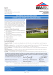
Software Package Design Expert version 2.0 Pad Expert Design and detailing of single stiff RC foundation pads with arbitrary shapes User Manual All rights reserved 2011 Pad Expert v 2.0/2011 Design and detailing of single stiff RC foundation pads with arbitrary shapes TABLE OF CONTENTS ABOUT THE PROGRAM ................................................................................................ 3 ENTERING DATA ......................................................................................................... 3 Working with tables .................................................................................................. 3 FILES .......................................................................................................................... 4 INPUT DATA ............................................................................................................... 4 Geometry data ......................................................................................................... 4 Loading data ............................................................................................................ 5 Design data ............................................................................................................. 5 Settlement data ........................................................................................................ 5 RESULTS ..................................................................................................................... 6 Base stress .............................................................................................................. 6 Uplift ....................................................................................................................... 6 Internal forces .......................................................................................................... 6 Design to Bulgarian code NPBStBK .............................................................................. 6 Bending .............................................................................................................. 6 Shear ................................................................................................................. 6 Punching ............................................................................................................. 6 Design to Eurocode 2 ................................................................................................ 7 Bending .............................................................................................................. 7 Shear ................................................................................................................. 7 Punching ............................................................................................................. 7 Settlement ............................................................................................................... 8 Foundation with zero stiffness................................................................................ 8 Foundation with infinite stiffness ............................................................................ 8 CALCULATION REPORT ............................................................................................... 8 DRAWING ................................................................................................................... 9 Settings ................................................................................................................... 9 External CAD system ............................................................................................ 9 Rounding ............................................................................................................ 9 Drawing scale and text size ................................................................................... 9 Bending schedule and BOM ................................................................................... 9 Top of concrete .................................................................................................... 9 Concrete cover .................................................................................................... 9 Starting mark number .......................................................................................... 9 Reinforcement ................................................................................................... 10 Export to ZWCAD (AutoCAD) and other applications .................................................... 10 WORKING WITH DESIGN EXPERT CAD GRAPHICAL ENVIRONMENT .......................... 10 Commands ............................................................................................................ 10 Screen view management ........................................................................................ 11 Zoom In............................................................................................................ 11 Zoom Out ......................................................................................................... 11 Zoom Window ................................................................................................... 11 Zoom All ........................................................................................................... 11 Pan .................................................................................................................. 12 Using a wheel mouse .......................................................................................... 12 Coordinate input ................................................................................................ 12 Select and deselect objects ...................................................................................... 12 Single ............................................................................................................... 12 Group ............................................................................................................... 12 All .................................................................................................................... 13 Deselect............................................................................................................ 13 Modify objects ........................................................................................................ 13 Delete .............................................................................................................. 13 Move ................................................................................................................ 13 Rotate .............................................................................................................. 13 стр. 2 от 21 Pad Expert v 2.0/2011 Design and detailing of single stiff RC foundation pads with arbitrary shapes Scale ................................................................................................................ 13 Mirror ............................................................................................................... 13 Stretch ............................................................................................................. 13 Copy ..................................................................................................................... 14 Method of transformation .................................................................................... 14 Number of repetitions ......................................................................................... 14 Pick points ........................................................................................................ 14 Printing graphics ..................................................................................................... 14 Copy graphics to other applications ........................................................................... 14 EXAMPLES ................................................................................................................ 15 Settlement of single foundations with different shapes ................................................ 15 Settlement data ...................................................................................................... 15 Example 1. Circular foundation ................................................................................. 16 Example 2. Circular hollow foundation ....................................................................... 17 Example 3. Square foundation .................................................................................. 18 Example 4. Rectangular foundation ........................................................................... 18 Example 5. Square hollow foundation ........................................................................ 19 Example 6. Calculation and design of rectangular foundation ........................................ 19 About the program Pad Expert is created for design and detailing of single stiff RC foundation pads with arbitrary shapes. Foundations are flat only, with constant thickness. Loads are applied on multiple rectangular columns, defined by their positions and sizes. Each column is loaded with vertical force N, bending moments Mx and My and shear forces Qx and Qy at top of foundation. Program calculates base stress and uplift, if any. Internal forces and main reinforcement are calculated for selected sections. Punching checks are performed with respect to column position (internal, edge or corner) and bending moments. Settlement is calculated for arbitrary shape for selected point or section and for either infinite or zero foundations stiffness. Software is quick and easy, with friendly user interface and is a valuable assistant to structural engineers. Input data and results are printed in a professional html report. Entering data Input data is divided into pages: You should pass through all pages by clicking their tab in order to enter all data. Click “Results” when you finish and you will go to another set of pages containing the results: You can go back to input data by clicking the first tab. Input data in each page is filled in text fields or tables. You can move to the next field with left click or Tab key. With Shift+Tab key combination you can go back to the previous field. Working with tables Most of the input data is filled in tables. The following commands are used with tables: - add a row – press the Ins key or the Up Enter to open a new row; button or when you go to the last column press - delete a row – press Backspace or Down cannot add or delete rows; button. Some tables have a fixed size and you - move the focus with a single cell – use keyboard arrows , , , ; стр. 3 от 21 Pad Expert v 2.0/2011 Design and detailing of single stiff RC foundation pads with arbitrary shapes - move the focus to the first or last row – press Page Up, Page Down, Home, End; - edit cell contents – press F2 or just start writing – an input box is opened in the current cell - end of cell edit – press Enter or arrow – the new data is saved to the cell; - cancel of cell edit – press Esc – existing data remains in the cell; - delete cell contents – select single or multiple cells and press Del; - area selection - use Shift+arrows (Page Up, Page Down, Home, End) or press left mouse button over the first corner, drag to the opposite corner and release the button. You can also click the first corner, hold shift key and click the second corner; - copy multiple cells – select an area and press Ctrl+C; - paste multiple cells - select an area or top-left cell and press Ctrl+V; You can copy to and from external programs like Word, Excel etc. Files Input data for each foundation is saved in a file with extension *. fun. Design output is written to a *. fun.html file in HTML format. You can open a file by the “Open” command from “File” menu or by Ctrl+O key combination. You can save a file by the “Save” command from “File” menu or by Ctrl+S key combination. When a file is saved for first time, a standard dialog appears where you should select file path and name. Otherwise, file is saved using current file name. You can change filename with the "New" command. Input data remains unchanged. To enter multiple foundations in one session do the following: input the first, calculate and draw, click “Save”, click “New”, input the second, calculate and draw, click “Save” and so on. Input data Geometry data Select foundation shape from the toolbar: , , , , , , , , enter dimensions and click the “Enter” button. Section is displayed in the drawing on the left side of the window. Dimensions are displayed in the pictures bellow: стр. 4 от 21 Pad Expert v 2.0/2011 Design and detailing of single stiff RC foundation pads with arbitrary shapes Coordinates x and y of outline points are entered for arbitrary shaped foundations. Circular and ring-shaped foundations are approximated as polygons with sufficient number of points. Foundation height and backfill height should be specified as well as their unit weights. Loading data Add the required number of rows in “Columns” table using the “+” key. Enter coordinates x, y and dimensions b and h for each column. Dimension b is along x axis. Then add the required number of load cases and their types as follows: “”S” – serviceability, “U” – ultimate and “E” – earthquake. Load values for vertical force N, bending moments Mx, My and shear forces Qx, Qy are entered for each column and each load case. Positive direction of vertical force is downwards. Bending moments are according to the picture on right. Loads from foundation self weight and backfill are added automatically. Additional uniform surface load can be entered in the beginning. Design data Select concrete grade and steel grade. Click the “Table” button to view material properties. Internal forces are calculated for selected sections. A section is defined by coordinates of endpoints that make a line. Actual length of that line is not used. Section dimensions b and h are entered instead as well as concrete cover a. Sections can be generated automatically by the “Generate sections” button for foundations with simple shapes and 1-2 columns. User should decide which are the relevant sections for more complex foundations and should fill in their endpoints and dimensions. Settlement data Settlement of arbitrary shaped foundation on elastic layered half-space is calculated for either infinite or zero stiffness using numerical integration. Most design codes use zero stiffness models in calculation formulas. Soil properties are entered in a table. You can add multiple layers using the "+" button. The following data is required for each layer: Eo - general elastic modulus; ni - Poisson ratio; h - layer thickness. Integration is performed until bottom of last layer is reached. Effective depth is not calculated by the program. Average base stress is required for calculations. It is automatically determined from the specified loads but you can change this value. Select stiffness: zero or infinite. For zero stiffness you should select either a point to calculate the settlement or a section to obtain the diagram of the deformed soil surface. For infinite stiffness, only one value is calculated for the settlement. Distribution of base stress, which in this case is not uniform, is determined as well. This requires mesh generation. Enter mesh size. The denser is the mesh, the more accurate are the results. A corresponding stiffness matrix is composed and a system of liner equations is solved. Calculation time increases with the mesh density so avoid too dense meshes. стр. 5 от 21 Pad Expert v 2.0/2011 Design and detailing of single stiff RC foundation pads with arbitrary shapes Results Base stress Average stress “pave”, edge stress “pedge” and maximum corner stress “pmax” are calculated as well as stress at each corner "pi". These values are compared to the admissible stresses. The ones that fail are colored in red. Values for each point are displayed in the drawing. Admissible stress R0 should be provided considering the foundation size and depth. The program does not adjust it automatically. Uplift Uplift is calculated when tension occurs in foundation base. Neutral line position and maximum stress are calculated by an iterative algorithm. Target condition is that the ground pressure should balance the external loads. Neutral line position is defined by two endpoints and is displayed in drawing as a blue dashed line. It is not recommended to have uplift except for seismic loads. Even then uplift should not be greater than half of the foundation. For complex shapes where “half” is not clearly defined uplift should not cross the center of area. Internal forces Total bending moments and shear forces are calculated for each load case and each section. All external forces, base stress, backfill weight, foundation sell weight and surface loads on one side of the section are included into calculations. Results are displayed in a table where rows correspond to load cases and columns correspond to sections. Design to Bulgarian code NPBStBK Bending Bending design is performed for the maximum bending moment from all load cases using the equation M As = Rs · (h0 - 0.5·x)·bs , where x = 1 – \ 1– 2·M Rb ·bs·h02 is compression zone height The program calculates the required count and diameter of bars using the specified spacing. If bending moment is negative, the reinforcement is positioned on top. Shear Shear design is performed assuming there will be no shear reinforcement and only concrete capacity is considered by the equation Qmax < Qb = 0,6·Rbt·bs·h0. Punching Punching design is performed for all columns. Columns can be eccentrically loaded and both bending moments are considered in the equation pmax = Nmax /Um + Mx /Wx + My /Wy < pu = Rbt·b·h0 стр. 6 от 21 Pad Expert v 2.0/2011 Design and detailing of single stiff RC foundation pads with arbitrary shapes Punching load Nmax is calculated from column load reduced by a factor of (1 – A1/A), where A1 = (bk +2·h0)·(hk +2·h0) is area enclosed by the effective perimeter at foundation base and A is total base area. That is how load inside the effective perimeter is excluded. U m = 2· (b k+ h k + 2·h 0) is length of mean effective perimeter and W x = (bk+ h 0)·((bk+ h 0) / 2 + (hk+ h0)) and W y = (hk+ h 0)·((hk+ h 0) / 2 + (bk+ h0)) are first moments of inertia of mean effective perimeter in plastic state assuming rectangular stress distribution. You can have columns close to edges and corners. If the effective perimeter intersects the concrete edge it is cut out. Columns that are too close (e.g. at expansion joints) may fail together under total load and with common effective perimeter. This is not considered by the program and user should perform additional calculations assuming there is one column with total load and dimensions. Design to Eurocode 2 Bending Bending design according to Eurocode 2 is performed by procedures defined in RC Expert 2.0. Detailed description of calculation procedures is provided in RC Expert.pdf. Shear Shear design is performed assuming there will be no shear reinforcement and only concrete capacity is considered by the equation Vmax< Punching Punching design for eccentrically loaded column is performed using the equation Critical perimeter u1 is located at distance 2d from column edge. стр. 7 от 21 Pad Expert v 2.0/2011 Design and detailing of single stiff RC foundation pads with arbitrary shapes For columns close to edge or corner, critical perimeter is reduced accordingly (see “Design to Bulgarian code” above). VEd is the punching load which is calculated from column load excluding base stress inside the effective perimeter. Reinforcement ratio is determined using the reinforcement calculated by bending design. The eccentricity is considered by the following factor Columns that are loaded by double eccentricity are calculated including both moments. First moment of area W1 is calculated in plastic state assuming rectangular stress distribution. Settlement You can choose between two theoretical models for calculation of settlement: Foundation with zero stiffness Settlement is calculated for uniform load p at foundation base neglecting the foundation stiffness. This approach is used by most design codes. Calculations are performed by numerical integration of stress in depth according to the equation h (z)·(1 – 2) = dz E0 0 ∫ Stress (z) is calculated by numerical integration of base load in polar coordinate system which base point is the target point where settlement is calculated. When settlement is calculated for a point, only one value is provided as a result. If section option is selected, a diagram is provided showing deformed soil surface along the section. Foundation with infinite stiffness Foundation is covered by square mesh with n elements and specified size a. First, deformation dij in point i due to unit force Fj=1 applied in point j is calculated for each i and j. Since it depends only on distance between points it is symmetrical and dij = dji. Total settlement in point i is a superposition of all points and is calculated by di = ∑ dij·Fj , where Fj is unknown. j Since foundation is infinite stiff, displacements of all points should be equal to one value d, which is also unknown. That is how we obtain a system with n equations and n+1 unknowns (n forces and 1 displacement). Last n+1 equation necessary for the system is the requirement for balance of vertical forces ∑Fi = p·A, where p is the average load at foundation base. Linear system of equation is solved and unknown forces Fj and final displacement d are calculated. Calculation report Professional html report can be generated for each foundation by going to the "HTML report" tab. You can include all or part of calculations by checking the "Print" boxes next to titles of results pages. Report is displayed in Internet Explorer by default, but other web browsers can be used as well. Most office programs like MS Word can edit html files. Report filename is data_file_name.html. It comes together with a folder data_file_name.html_files. Always keep together report file with the folder. Otherwise pictures and formatting will be lost. стр. 8 от 21 Pad Expert v 2.0/2011 Design and detailing of single stiff RC foundation pads with arbitrary shapes Drawing Go to “Drawing” tab. Design Expert CAD is loaded and foundation plan and section are displayed. There is a panel on the left side, where you can enter different settings or additional data for the foundation as well as bottom and top reinforcement in both directions. Click the “Generation of drawing” button each time you want to apply these settings to the drawing. Settings External CAD system Select an external CAD system (ZWCAD® or AutoCAD®) to export to. See “Export to ZWCAD (AutoCAD) and other applications”. Rounding You can set different rounding factors for dimensions and total lengths of bars. Default values are 2.5 cm and 5.0 cm, respectively. Drawing scale and text size Drawing scale and printed text size should be specified. Actual text size in the drawing is calculated automatically for the specified scale. Bending schedule and BOM Bending schedule includes bar sketches with all dimensions as well as total number, length, unit weight and total weight for each bar mark. Bill of materials (BOM) includes reinforcement weights for each diameter, total weight (kg), concrete volume (m3) and formwork area (m2). Top of concrete Enter relative level for top of concrete (t.o.c.). Ground level (g.l.) and foundation level (f.l.) are calculated using specified foundation depth and thickness. All levels are displayed in the drawing. Concrete cover Concrete cover is the distance from surface of bars to concrete surface. Only one value is possible for all surfaces (top, bottom and sides). If there is a difference, use the most unfavorable value. Starting mark number Use this setting when you are going to have several foundations in one CAD drawing. Enter the starting mark number to be greater than the last mark number of the previous foundation. стр. 9 от 21 Pad Expert v 2.0/2011 Design and detailing of single stiff RC foundation pads with arbitrary shapes Reinforcement Enter diameter and spacing for bottom and top bars in both directions X and Y. When you go to the „Drawing” page for first time, reinforcement is automatically selected by the program. Selection is based on design results for most unfavorable section that crosses the respective bars. Bars can be straight or “U”-shaped. Higher foundations may require additional horizontal reinforcement along sides which is not generated in this version of the program and should be added manually. Foundations with complex shapes are meshed automatically and may have different bar lengths in same direction. Bars longer than 12 m are not split and lapped automatically. Export to ZWCAD (AutoCAD) and other applications Click the / button to export the drawing to ZWCAD/AutoCAD. Version 2009i and higher is supported for ZWCAD and 15 (2000) and higher is supported AutoCAD. If ZWCAD/AutoCAD is opened then program draws into the active document. If it is not opened then new session is started automatically. Drawing is made from lines, polylines, texts, dimension lines, circles and solid hatches. There are no blocks or other complex objects and drawing can be easily edited. In order to achieve better results set "Text Placement" to be "Over the Dimension Line, Without a Leader" for current dimension properties. Objects are divided in layers such as „AXES”, „CONC”, „BARS”, "SEC”, „TEXT” etc. With submenu / "Save script file *.scr" you can export a script file with the necessary commands for drawing the foundation. Script can be loaded into ZWCAD/AutoCAD with the “SCRIPT” command or "Tools\Run Script..." menu. Export to other CAD systems can be developed on request. You can also export the drawing as bitmap or metafile to other application through system clipboard. Working with Design Expert CAD graphical environment Version 2.0 of Design Expert includes embedded graphical environment with a lot of commands to review, edit and print drawings. Commands Each command can be activated by typing its full name or some of the aliases into the command line or by the respective button in the toolbar. Descriptions of all graphical environment commands are provided in the following table: Command Abbreviation ACAD Description Transfers the drawing into ZWCAD (AutoCAD) COPYBMP CB Copies drawing to Clipboard as Bitmap COPYMETAFILE CM Copies drawing to Clipboard as Metafile DELETE E, D, DEL Deletes selected objects DESELECTALL DE, DESEL Deselects all objects DISTANCE DI, DIST Measures distances EXIT E, X, EX Ends current program session GRID GR Turns grid on/off MIRROR MI Mirrors objects in the drawing MOVE M, MO Moves objects in the drawing стр. 10 от 21 Pad Expert v 2.0/2011 Design and detailing of single stiff RC foundation pads with arbitrary shapes NEW N Opens a new file OPEN O, OP Opens an existing file ORTHO OR Turns orthogonal drawing on/off OSNAP OS Turns snap to points on/off the PRINT PR, PRN Prints current drawing display QUIT Q Same as EXIT REDO RE Restores last command REDRAW RD Redraws the screen REPLICATE CP, CO, COPY Copies objects in the drawing ROTATE RO Rotates objects in the drawing RTPAN PA, PAN Moves the screen view SAVE S, SA Saves a file to disc SCALE SC Scales objects in the drawing SCRIPT SCR Saves SCRIPT file with commands for ZWCAD/AutoCAD SELECT SE, SEL, READY Enters select mode SELECTALL A, ALL, SELALL Selects all objects SNAP SN Turns coordinate snap on/off UNDO U Undoes last command ZOOMIN ZI, Z+ Increases screen view ZOOMLIMITS ZL, ZA, ZE Increases screen view to fit all objects in the drawing ZOOMOUT ZO, Z- Decreases screen view ZOOMWINDOW ZW Increases screen view to fit the selected window Screen view management All objects in the drawing are defined by their coordinates in Cartesian coordinate system ОХУ, which is displayed in program window in certain scale. This view can be scaled and moved using the following commands: Zoom In Click the button. Screen view is enlarged by 25%. Zoom Out Click the button. Screen view is shrinked by 25%. Zoom Window Click the button. Click with left mouse button, and move the cursor to enclose the objects, which you want to zoom into a rectangular window. Click once again. The image is zoomed to fit the selected window into the screen. Zoom All Click the button. This command scales and centres the view to fit all objects into the program window. стр. 11 от 21 Pad Expert v 2.0/2011 Design and detailing of single stiff RC foundation pads with arbitrary shapes Pan Click the button. Enter first point, move the cursor at the desired direction and enter second point. Screen view is moved at direction and distance, defined by the vector between the two points. Using a wheel mouse If you have a wheel mouse with three buttons you can pan without the above commands. Click and hold the middle button, move the mouse and release the button to pan the screen view. Roll the wheel forward and backward to zoom in and zoom out the screen view, respectively. Coordinate input All objects in the drawing are defined in OXY coordinate system, projected to the screen. Some commands require the user to enter coordinates of points. There are two ways to enter point coordinates: 1. By left mouse click in the preferred position. Current cursor coordinates are displayed in status bar when moving the mouse. Precision tools “Snap”, “OSnap” and “Ortho” help you to snap the cursor to grid with spacing of 5 mm, to an existing point or restrain it to horizontal (vertical) line. When precision tools are turned off then a mouse click produces imprecise coordinates depending on current view scale. 2. By typing with the keyboard. Write coordinates in the command line and press “Enter”. It is not necessary to click into the command line first. It is activated automatically when you press the first key. Following formats are allowed for coordinate input: Name Format Example Description Absolute X;Y 10,5;15 Absolute coordinates in ОХУ coordinate system. Relative _Х;У _25;35 Relative distances "25" and "35" along Х and У from the last entered point. Polar <о;L <45;100 Relative distance "100" from the last entered point measured at angle 45о from Х axis. 50 Relative distance "50" from the last entered point, measured at direction defined by the cursor. Distance L Select and deselect objects Selection creates a group of objects using the mouse in order to apply certain command on them (e.g. erase). It can be done before or after the command. Objects in locked layers cannot be selected even when they are visible on screen. You can go to “Selection” mode by pressing the button or the “Esc” key. The following ways for selection are available: Single Position the mouse cursor over the object so that it crosses the small square and press the left button. Selected object is colored in red. Group Click the left mouse button near the objects you want to select and move the cursor to draw a rectangle around them. Second click will select all objects which: - are entirely inside the rectangle if you draw from left to right; стр. 12 от 21 Pad Expert v 2.0/2011 Design and detailing of single stiff RC foundation pads with arbitrary shapes - either cross or fit inside the rectangle if you draw from right to left. All Click the button or press Ctrl+A. You will select all objects, except those which are in locked layers. Deselect Click the button or press Ctrl+D or Еsc. All selected objects will be deselected. To deselect a single object, click on it with right mouse button. The “Undo” command undoes last selection. Modify objects Delete Removes all selected objects from both memory and screen. In case of error objects can be restored using the “Undo” command immediately after that. Delete command is started by the button or “Del” key. Move Moves the selected objects along specified vector of translation. Command is performed in the following sequence: 1) Select objects. 2) Press the button. 3) Pick the coordinates of the first and the second point of the translation vector. Rotate Rotates the selected objects around specified centre and angle of rotation. You are required to enter two points. The first point defines the rotation centre and the second one is for the angle. Angle is measured from the positive X axis towards the vector defined by the points. Command is performed in the following sequence: 1) Select objects. 2) Press the button. 3) Enter first and second point. Scale Scales the selected objects with a specified factor. This command requires two points: The first one is for the base point and the second one defines the scale factor. Command is performed in the following order sequence: 1) Select objects. 2) Press the button. 3) Enter first and second point. Mirror Mirrors the selected objects about a line, defined by two points. Command is performed in the following order: 1) Select objects. 2) Press the button. 3) Enter first and second point. Stretch Geometric objects can be modified by stretching their grip points. Select the object first. Click with left button on the desired point to “catch” it. Move the cursor to the new position and click again to release it. Stretching a centre of a circle moves the circle, and stretching points at 0°, 90°, 180°, 270° changes the radius. If you had picked a point and you want to release it press “Esc” or right mouse button. стр. 13 от 21 Pad Expert v 2.0/2011 Design and detailing of single stiff RC foundation pads with arbitrary shapes Copy Creates multiple copies of the selected objects. Command is started with the “Copy” dialog appears where you have to define the following parameters: button. The Method of transformation The coordinates of the copied objects are calculated from the coordinates of the source objects through the preferred transformation as follows: - translation ; - rotation ; - copy ; - mirror . Number of repetitions Objects can be copied multiple times as specified. Pick points The “Copy” dialog disappears and the user is prompted to enter two points that define the transformation parameters (vector of translation, angle of rotation etc.) If the “First-Second” option is selected, these points define the position of the second object relative to the first and the others are located after it. If the option “First-Last” is selected, these points define the position of the last object relative to the first and the others are located between them. Printing graphics Current screen view can be printed with the button. A dialog box for selection of printer and paper format is displayed. Press "Start" to send the drawing directly to the printer. Only part of the drawing which is visible in the program window is printed. Copy graphics to other applications The drawing can be copied to the Clipboard and then pasted to a CAD program or text editor (e.g. Word) and printed. Only part of the drawing which is visible in the program window is copied. Two formats are supported: - Raster (Bitmap) – Command name is "COPYBITMAP". Data for the color of each pixel in the image is stored. Image quality decreases when image is resized. Image can be opened with MS Paint. - Vector (Metafile) – Command name is "COPYMETAFILE". Coordinates of geometrical objects and their equations are stored. Pixels are calculated each time, when the image is displayed on screen. In that case the image can be resized without affecting the quality. When image contains a lot of objects it gets heavier and raster format is preferable. It can be pasted to other programs in two formats - Metafile and Enhanced Metafile. The second one is recommended. The program MS Word converts it to Word Picture after insertion. If you try to edit the picture, it is possible to damage it. стр. 14 от 21 Pad Expert v 2.0/2011 Design and detailing of single stiff RC foundation pads with arbitrary shapes Examples Settlement of single foundations with different shapes Next examples use the same input data as follows: Surface load Backfill depth - p = 0.000 h з = 0.000 kN/m2 m Backfill unit weigh - з = 18.000 kN/m3 Foundation height - h ф = 0.000 m Foundation unit weigh Foundation depth - ф = 25.000 t = 0.000 Admissible base stress - Ro = 200.000 kN/m3 m kPa Settlement data Soil layers No 1 Eo, kPa ni 20000 0.2 H, m 1000 Nominal base load for settlement - pn = 200.000 kPa Foundation with zero stiffness Target point X = 0.000 m, Y = 0.000 m, Number of divisions for numerical integration: 20 Infinite stiff foundation Mesh size: 0.200 m стр. 15 от 21 Pad Expert v 2.0/2011 Design and detailing of single stiff RC foundation pads with arbitrary shapes Example 1. Circular foundation Geometry Data Outline Points Shape Type: Circular R= 2.000 m n= 32.000 m No X, m Y, m No X, m Y, m 1 2.000 0.000 17 -2.000 0.000 2 1.962 0.390 18 -1.962 -0.390 3 1.848 0.765 19 -1.848 -0.765 4 1.663 1.111 20 -1.663 -1.111 5 1.414 1.414 21 -1.414 -1.414 6 1.111 1.663 22 -1.111 -1.663 7 0.765 1.848 23 -0.765 -1.848 8 0.390 1.962 24 -0.390 -1.962 9 0.000 2.000 25 0.000 -2.000 10 -0.390 1.962 26 0.390 -1.962 11 -0.765 1.848 27 0.765 -1.848 12 -1.111 1.663 28 1.111 -1.663 13 -1.414 1.414 29 1.414 -1.414 14 -1.663 1.111 30 1.663 -1.111 15 -1.848 0.765 31 1.848 -0.765 16 -1.962 0.390 32 1.962 -0.390 Settlement - foundation with zero stiffness smax = 3.82 cm Manual check s = p∙B∙∙(1 – 2)/E0 = 200∙4.00∙1.00∙(1 – 0.22)/20000 =0.0384 m = 3.84 cm - infinite stiff foundation smax = 3.02 cm Manual check s = p∙B∙∙(1 – 2)/E0 = 200∙4.00∙0.79∙(1 – 0.22)/20000 =0.0302 m = 3.02 cm стр. 16 от 21 Pad Expert v 2.0/2011 Design and detailing of single stiff RC foundation pads with arbitrary shapes Example 2. Circular hollow foundation Geometry Data Outline Points Shape Type: Circular hollow No X, m Y, m No X, m Y, m 1 2.000 0.000 34 1.000 0.000 2 1.962 0.390 35 0.981 -0.195 3 1.848 0.765 36 0.924 -0.383 4 1.663 1.111 37 0.831 -0.556 5 1.414 1.414 38 0.707 -0.707 6 1.111 1.663 39 0.556 -0.831 7 0.765 1.848 40 0.383 -0.924 8 0.390 1.962 41 0.195 -0.981 9 0.000 2.000 42 0.000 -1.000 10 -0.390 1.962 43 -0.195 -0.981 11 -0.765 1.848 44 -0.383 -0.924 12 -1.111 1.663 45 -0.556 -0.831 13 -1.414 1.414 46 -0.707 -0.707 14 -1.663 1.111 47 -0.831 -0.556 R= 2.000 m 15 -1.848 0.765 48 -0.924 -0.383 n= 32.000 m 16 -1.962 0.390 49 -0.981 -0.195 t= 1.000 m 17 -2.000 0.000 50 -1.000 0.000 18 -1.962 -0.390 51 -0.981 0.195 19 -1.848 -0.765 52 -0.924 0.383 20 -1.663 -1.111 53 -0.831 0.556 21 -1.414 -1.414 54 -0.707 0.707 22 -1.111 -1.663 55 -0.556 0.831 23 -0.765 -1.848 56 -0.383 0.924 24 -0.390 -1.962 57 -0.195 0.981 25 0.000 -2.000 58 0.000 1.000 26 0.390 -1.962 59 0.195 0.981 27 0.765 -1.848 60 0.383 0.924 28 1.111 -1.663 61 0.556 0.831 29 1.414 -1.414 62 0.707 0.707 30 1.663 -1.111 63 0.831 0.556 31 1.848 -0.765 64 0.924 0.383 32 1.962 -0.390 65 0.981 0.195 33 2.000 0.000 66 1.000 0.000 Settlement - foundation with zero stiffness - smax = 1.91 cm Manual check s = p∙(B2−B1)∙∙(1– 2)/E0 = 200∙(4.00−2.00)∙1.00∙(1–0.22)/20000 = 0.0192m =1.92cm - infinite stiff foundation - smax = 2.30 cm стр. 17 от 21 Pad Expert v 2.0/2011 Design and detailing of single stiff RC foundation pads with arbitrary shapes Example 3. Square foundation Geometry Data Outline Points Shape Type: Square b= 4.000 m h= 4.000 m Settlement - foundation with zero stiffness - No X, m Y, m 1 -2.000 -2.000 2 2.000 -2.000 3 2.000 2.000 4 -2.000 2.000 smax = 4.30 cm Manual check - s = p∙B∙∙(1 – 2)/E0 = 200∙4.00∙1.12∙(1 – 0.22)/20000 = 0.043m = 4.30cm - infinite stiff foundation - smax = 3.30 cm Manual check - s = p∙B∙∙(1 – 2)/E0 = 200∙4.00∙0.88∙(1 – 0.22)/20000 = 0.043m = 3.38cm Example 4. Rectangular foundation Geometry Data Outline Points Shape Type: Rectangular b= 8.000 m h= 2.000 m Settlement - foundation with zero stiffness No X, m Y, m 1 -4.000 -1.000 2 4.000 -1.000 3 4.000 1.000 4 -4.000 1.000 smax = 3.76 cm 2 Manual check - s = p∙B∙∙(1 – )/E0 = 200∙2.00∙1.96∙(1 – 0.22)/20000 = 0.0376m = 3.76cm - infinite stiff foundation smax = 2.99 cm Manual check - s = p∙B∙∙(1 – 2)/E0 = 200∙2.00∙1.61∙(1 – 0.22)/20000 = 0.0376m = 3.09cm стр. 18 от 21 Pad Expert v 2.0/2011 Design and detailing of single stiff RC foundation pads with arbitrary shapes Example 5. Square hollow foundation Geometry Data Outline Points Shape Type: Square hollow b= 8.000 m h= 8.000 m t1 = 2.000 m t2 = 2.000 m Settlement - foundation with zero stiffness No X, m Y, m 1 -4.000 -4.000 2 4.000 -4.000 3 4.000 4.000 4 -4.000 4.000 5 -4.000 -4.000 6 -2.000 -2.000 7 -2.000 2.000 8 2.000 2.000 9 2.000 -2.000 10 -2.000 -2.000 smax = 4.29 cm Manual check s = p∙(B2 – B1)∙∙(1 – 2)/E0 = 200∙(8.00 – 4.00)∙1.96∙(1 – 0.22)/20000 = 0.0430m = 4.30cm Example 6. Calculation and design of rectangular foundation Geometry Data Outline Points Shape Type: Rectangular b= 4.000 m h= 3.000 m Surface Load - p= 0.000 kN/m2 Backfill Height - hз = 1.000 m Backfill Unit Weight - з = 18.000 No X, m Y, m 1 -2.000 -1.500 2 2.000 -1.500 3 2.000 1.500 4 -2.000 1.500 kN/m3 стр. 19 от 21 Pad Expert v 2.0/2011 Design and detailing of single stiff RC foundation pads with arbitrary shapes Foundation Height - hф = Concrete Unit Weight - ф = 25.000 Foundation Depth - 0.700 t= Allowable Base Stress - 1.700 Ro = 200.000 m kN/m3 m kPa Loads Data Number Of Load Cases: 3 Columns Load Cases No x, m y, m b, m h, m Case Тип 1 0.000 0.000 0.600 0.600 L1 U L2 S L3 E Load Types: S - Serviceability, U - Ultimate, E - Earthquake Loads Case Column L1 K1 L2 L3 N, kN Mx, kNm My, kNm 2200.000 0.000 0.000 K1 1800.000 0.000 0.000 K1 1700.000 500.000 0.000 Design Data Concrete - B20 - Rb = 11.50 MPa b = 1.000 Reinforcement - AIII - Rs = 375 MPa s = 1.000 Design Sections No X1, m Sections Dimensions Y1, m X2, m Y2, m Section b,m h, m а, m 1 0.300 -1.500 0.300 1.500 S1 3.000 0.700 0.050 2 -0.300 -1.500 -0.300 1.500 S2 3.000 0.700 0.050 3 -2.000 0.300 2.000 0.300 S3 4.000 0.700 0.050 4 -2.000 -0.300 2.000 -0.300 S4 4.000 0.700 0.050 Settlement Data Soil Layers No 1 Eo, kPa ni H, m 12000 0 6.7 Zero Stiffness Foundation Load For Settlement Calculation - pn = 186.000 kPa Calculate Settlement For Point X = 0.000, Y = 0.000 Divisions for Numerical Integration: 20 стр. 20 от 21 Pad Expert v 2.0/2011 Design and detailing of single stiff RC foundation pads with arbitrary shapes Base Stress Results Base Stress [kPa] Neutral Axis Coordinates (Uplift) [m] L1-И L2-Н L3-С Load X1 Y1 X2 Pave 227.7 185.5 Pedge 227.7 Pmax Y2 177.2 L1 0.000 0.000 0.000 0.000 185.5 239.7 L2 0.000 0.000 0.000 0.000 227.7 185.5 239.7 L3 0.000 0.000 0.000 0.000 P1 227.7 185.5 114.7 P2 227.7 185.5 239.7 P3 227.7 185.5 239.7 P4 227.7 185.5 114.7 Base Stress Checks - R = 200 kPa; 1,3·R = 260 kPa; 1,5·R = 300 kPa; 4·R = 800 kPa Internal Forces Results Bending Moments For Each Load Case [kNm] Section M1 M2 S1 794.8 650.3 S2 794.8 S3 S4 Shear Forces For Each Load Case [kN] M3 Section Q1 Q2 Q3 808.3 S1 935.0 765.0 905.8 650.3 420.0 S2 -935.0 -765.0 -539.2 528.0 432.0 408.0 S3 -880.0 -720.0 -680.0 528.0 432.0 408.0 S4 880.0 720.0 680.0 RC Design Results Bending Design Section Mmax, kNm x, cm As, cm2/m Reinforcement S1 808.30 3.71 11.38 16N18 през 20 - долна S2 794.75 3.65 11.18 16N18 през 20 - долна S3 528.00 1.79 5.49 21N12 през 20 - долна S4 528.00 1.79 5.49 21N12 през 20 - долна Shear Design Section Qmax. kN Qb. kN S1 935.00 < 1053.00 S2 935.00 < 1053.00 S3 880.00 < 1404.00 S4 880.00 < 1404.00 Qmax < Qb = 0.6·Rbt·b·h0, Punching Design Column Um. cm pmax.kN/cm pu.kN/cm K1 500.00 4.51 < 5.85 pmax = Nmax/Um + Mx/Wx + My/Wy < pu = Rbt·h0 Settlement smax = 4.71 cm стр. 21 от 21