1
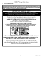
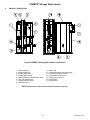
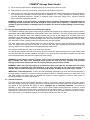
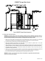
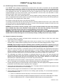
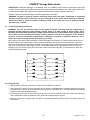
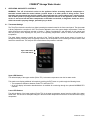
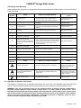
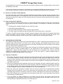
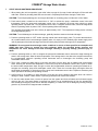
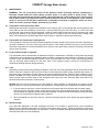
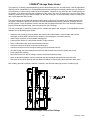
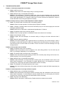
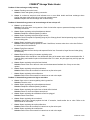
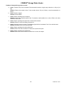
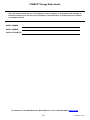
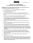
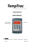
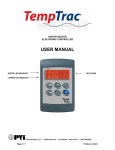
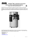
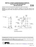
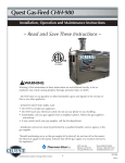
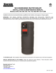
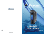
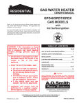
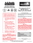
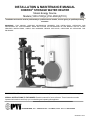
INSTALLATION & MAINTENANCE MANUAL COBREX® STORAGE WATER HEATER Steam Energy Source Models (1200-7200)(L)(150-4500)A(TCX) Installation and service must be performed by a qualified service installer, service agency or qualified plumbing contractor. IMPORTANT: THIS MANUAL CONTAINS INFORMATION REQUIRED FOR INSTALLATION, OPERATION AND MAINTENANCE OF THIS EQUIPMENT. READ AND FOLLOW THE INFORMATION IN THIS MANUAL AND ALL OTHER PROVIDED INSTRUCTIONS, LABELS AND MARKINGS BEFORE INSTALLING, OPERATING OR SERVICING THIS EQUIPMENT. TO THE INSTALLER: After installation, these instructions must be given to the equipment user or left near the appliance. SPECIAL INSTRUCTIONS TO THE OWNER: Retain this manual for future reference. These instructions contain important information that will help you in maintaining and operating this appliance. PVI INDUSTRIES, LLC – 3209 Galvez Ave. - Fort Worth, Texas 76111 - 1-800-433-5654 PV500-65 10/15 COBREX® Storage Water Heater TABLE OF CONTENTS 1 Safety Considerations 2 Product Description 3 Water Heater Installation 4 5 6 3.1 Warranty 3.2 Checking Equipment Before You Install 3.3 Codes 3.4 Electrical Requirements 3.5 Handling and Locating the Water Heater 3.6 Service Clearances and Clearance to Combustibles General Piping Guidelines 4.1 Potable Water Inlet and Outlet Connections 4.2 Storage Tank Temperature and Pressure Relief Valve Piping 4.3 Cathodic Protection 4.4 Water Inlet / Outlet Connections 4.5 Heat Exchanger Pressure Relief Valve Piping 4.6 Steam & Condensate Connections 4.7 Connecting Pump(s) and Valve(s) 4.8 Filling the Unit Operating and Safety Controls 5.1 Thermostat Settings 5.2 High Water Temperature Limit Control 5.3 Electronic Low Water Cut-Off (optional) 5.4 Alarm on Any Failure (optional) Description of Operation 6.1 Sequence of Operation 7 Start-Up and Shut-Down Procedure 8 Maintenance 9 8.1 Temperature and Pressure Relief Valve 8.2 Thermostats and Temperature Limiting Device 8.3 Control Valve Actuator (if supplied) 8.4 Tank 8.5 Heat Exchanger 8.6 Recommended Maintenance Schedule Troubleshooting Guide Warranty forms ship separately with each water heater. 2 PV500-65 10/15 COBREX® Storage Water Heater 1 SAFETY CONSIDERATIONS WARNING: Do not use this appliance if any part has been under water. Immediately call a qualified service technician to inspect the unit and to replace any part of the control system and any other items affecting safe appliance operation and which has been under water. Failure to follow these instructions can cause property damage, personal injury, or exposure to hazardous materials or death. IMPORTANT SAFETY NOTE It takes only 5 seconds of skin contact with 140 °F water to cause a second degree burn! You must protect against high water temperatures at all lavatories, tubs, showers and other points of hot water contact. Accidental scalding from high water temperatures is a greater risk in some types of installations. Some examples are: HOMES FOR THE MENTALLY OR PHYSICALLY HANDICAPPED HOSPITALS AND NURSING HOMES ELDER CARE FACILITIES AND REST HOMES ORPHANAGES AND CHILD CARE FACILITIES OTHER INSTALLATIONS - WHERE RESPONSE TO CONTACT WITH HOT WATER MAY BE SLOWER OR WHERE THE DANGER OF HOT WATER CONTACT IS GREATER. Thermostatically controlled mixing valves must be used in the design of the potable hot water system. Potable hot water should be tempered to no more than 110°F when used for bathing or other personal uses. Good engineering practice mandates the use of thermostatically controlled mixing valves set at 120°F or less to keep the delivered water temperature below scalding temperatures. 3 PV500-65 10/15 COBREX® Storage Water Heater 2 PRODUCT DESCRIPTION Typical COBREX® Storage Water Heater Construction 1. 2. 3. 4. 5. 6. 7. 8. Heat Exchanger Control Enclosure Potable Water Inlet Potable Water Outlet Heat Exchanger Pressure Relief Valve Tank T&P Relief Valve Isolation Shutoff Valves Tank Drain Valve 9. 10. 11. 12. 13. 14. 15. Steam Inlet Condensate Outlet (from trap fitting) Electronic Operating Control Condensate Control Valve Lifting Point (2 places) Heat Engine Storage Tank NOTE: Components, controls and connection locations may vary. 4 PV500-65 10/15 COBREX® Storage Water Heater 3 WATER HEATER INSTALLATION 3.1 Warranty Factory warranty does not cover improper installation or operation. (See warranty for complete details). Warranty exclusions include but are not limited to failure or malfunctions resulting from: 1. Failures to properly apply, install, operate, or maintain the appliance in accordance to printed instructions. 2. Abuse, alteration, accident, fire, flood and the like. 3. Corrosive or contaminated atmosphere. 3.2 Checking Equipment Before You Install Inspect the unit completely upon receipt from the freight carrier before signing the bill of lading. Inspect the appliance and all accompanying parts for signs of impact or mishandling. Verify the total number of pieces shown on packing slips with those actually received. Contact the freight carrier immediately if any damage or shortage is detected. 3.3 Codes The equipment must be installed in accordance with the instructions in this manual, appliance markings and supplemental instructions and in compliance with those installation regulations in force in the local area where the installation is to be made. In the absence of such regulations, the installation must be in accordance with the instructions in this manual, appliance markings, supplemental instructions and in compliance with the latest edition of the applicable state and local mechanical and plumbing codes. Authorities having jurisdiction must be consulted before installation is made. The storage tank conforms to the current edition of the ASME Boiler and Pressure Vessel Code Section IV, Part HLW and the heat exchanger conforms to the current edition of the ASME Boiler and Pressure Vessel Code Section VIII. 3.4 Electrical Requirements The standard appliance is wired for 120VAC/1ph/60Hz service. For alternate electrical service connection, see specific literature supplied with the appliance or contact the factory. The appliance must be electrically grounded in accordance with the requirements of the authority having jurisdiction or in the absence of such requirements, with the latest edition of the National Electrical Code ANSI/NFPA No. 70. When the unit is installed in Canada, it must conform to the CSA C22.1, Canadian Electrical Code and/or Local Electrical Codes. • Supply the electrical service specified on the water heater data decal to each water heater. Separate electrical circuits are recommended for multiple appliance installations. • Branch circuit protection and a disconnecting means must be furnished by the installer. Refer to the provided wiring diagram when installing or troubleshooting electrical components of this appliance. • All wiring between the water heater and field installed devices must be made with type T copper wire of proper size for the appliance load. Damage resulting from use of aluminum wiring is not covered by the product warranty. • Line voltage wire exterior to the water heater must be enclosed in approved conduit or approved metal clad cable. • Protect all water heater internal and external electrical components, wiring and electrical service connections from water (dripping, spraying, rain, etc.) at all times. 3.5 Handling and Locating the Water Heater WARNING: Use industry standard safe rigging methods, such as including the use of straps and spreader bars and lifting from the water heater base skid assembly, when attempting to lift or move this product. Failure to follow industry standard safe rigging methods can cause uncontrolled tipping or dropping the water heater, resulting in property damage, personal injury or death. 1. Do not attempt to move or lift the water heater by the plumbing connections or heat exchanger. Lift the storage tank only by the skid using industry standard safe rigging methods. Lift the Heat Engine by the two lifting points using industry standard safe rigging methods. 2. Locate the water heater in a clean and dry area as close as possible to the greatest hot water usage and as near to steam supply and/or electrical power as practical. 3. Confirm that the system utilities are adequate to meet the water heater requirements on the information decal. 4. These water heaters are suitable for indoor installation only and must not be subject to freezing. 5. The water heater must be placed on a level surface. Installation on a 4 inch to 6 inch housekeeping pad is recommended. 5 PV500-65 10/15 COBREX® Storage Water Heater 6. Locate the water heater so that if water connections should leak, water damage will not occur. Water damage is not covered by the manufacturer’s warranty. 7. Locate the water heater near a suitable drain capable of accepting hot water discharge (potentially in excess of 210°F) from the water heater temperature and pressure relief valve 8. Floor mounting provisions and tie down anchor points are provided. Pilot holes are indicated on the jacket for securing the equipment. Code requirements vary by geographical location, additional strapping or braces may be required. Please refer to your local codes for specific requirements. 9. Once the water heater storage tank and heat engine are placed in their final location, carefully remove all shipping supports and bracing. 3.6 Service Clearances and Clearance to Combustibles Service Clearance: A minimum service clearance of 18" is recommended on all sides and above the appliance to facilitate easy access for inspection and service of installed components. Optional equipment may increase the clearance requirements. Also allow sufficient space for installing and servicing connections such as building water, electrical, pump, steam and other auxiliary/optional equipment. Clearance to Combustibles: The minimum clearances to unprotected combustible materials are 24 inches from the front, 8 inches from the top and 8 inches from the top, left and right sides of the appliance. 4 GENERAL PIPING GUIDELINES 4.1 Potable Water Inlet and Outlet Connections CAUTION: To maintain tank corrosion resistance and warranty, do not contact inside (water side) of tank, nozzles or stainless steel fittings with ferrous (i.e. iron or steel) metal, tools, brushes, etc. IMPORTANT: Do not use galvanized, dielectric or steel pipe, nipples or fittings when making waterside connections. Use only non-ferrous waterside materials. 1. All domestic and steam pipes should be flushed before assembly and installation. Failure to flush lines could cause components to clog or malfunction. 2. Align and attach the pipe union or flanged connections from the heat exchanger to pipe union connections from the storage tank, as shown in the product description. To avoid shipping damage, some piping assemblies may be disconnected and separately secured to the shipping container. Such assemblies must be reconnected. Up to ten additional equivalent feet of pipe can be added to the piping between the tank and heat exchanger, if desired. If the distance between the storage tank and heat exchanger is in excess of ten equivalent feet, the customer must contact the factory to determine if they must increase the pump size to accommodate for the additional pressure drop. 3. Always use a back-up wrench on tank and heat engine piping when tightening unions, valves, flanges, etc. Damage caused by plumbing mistakes, such as over-tightening or not using a backup wrench is not covered by warranty. 4. Piping and components connected to the water heater must be suitable for potable water, for the water temperatures they will experience and for their application. 5. Install shut-off valves and unions in the potable water, steam and condensate piping to aid in servicing. Use caution when threading pipe nipples into tank and heat engine connections to prevent cross threading, or overtightening. 6. Thermal Expansion Tank – If the water heater is installed in a closed water supply system, such as one having a back-flow preventer in the cold water line, provide thermal expansion control. 7. Pipe the Y-strainer blow-down valve and storage tank drain valve to a suitable open drain capable of accepting hot water at the temperature discharged when opening the water heater drain valves. 8. When two or more water heaters are piped in parallel it is important that the piping systems are balanced to assure the full combined capacity is realized. Reverse return piping is recommended for multiple unit installations. 6 PV500-65 10/15 COBREX® Storage Water Heater 9. Do not use the water heater or attached piping as an electrical ground of any kind. 10. After plumbing, confirm all connections, components and fittings are leak free. 11. After checking for leaks, the heat exchanger and all steam and hot potable water piping must be insulated to the minimum pipe insulation thickness specified in ASHRAE 90.1, “Energy Standard for Buildings Except Low-Rise Residential buildings.” Insulate or otherwise protect cold water supply lines if subject to freezing during operation or shutdown periods. WARNING: Insulate or guard all surfaces containing steam or hot water. Uninsulated or unguarded surfaces containing steam or hot water can be hot enough to cause severe burns instantly, if contacted. Failure to insulate or guard all surfaces containing steam or hot water can result in property damage, personal injury, or death. 4.2 Storage Tank Temperature and Pressure Relief Valve Piping The COBREX® Storage water heater storage tank is supplied with temperature and pressure relief valve(s) sized in accordance with the ANSI/ASME Boiler and Pressure Vessel Code, Section IV. The relief valve(s) must be threaded directly into the dedicated relief valve fitting(s) located near the top of the storage tank and each relief valve discharge must be separately plumbed to an appropriate floor drain. The discharge line must not be smaller than the relief valve opening, must allow complete drainage of the valve and line and it must be positioned in the floor drain, such that water or steam forcefully exiting the drain line does not openly splash. The water heater must not be operated without a correctly installed, properly sized and properly operating relief valve. If a replacement relief valve is required, it must be of the same type, temperature and pressure rating, and relieving capacity as the original relief valve supplied with the water heater. Do not plug or restrict the relief valve or the relief valve drain line. It is strongly recommended that the relief valve(s) should be manually operated at least once a year. If water does not freely flow from the manually operated relief valve or if it does not fully reseat when released, the relief valve must be replaced with a new relief valve meeting the same ratings. WARNING: Do not install a reducing coupling, valve or other restriction between the relief valve discharge and a suitable floor drain. Such restriction could prevent the valve from fully relieving if the pressure settings are exceeded, which could result in property damage, personal injury or death. WARNING: Secure the relief valve piping to a suitable floor drain such that very hot water does not openly splash during a significant relief valve discharge. If the relief valve pipe is not routed and secured to a suitable drain, hot water discharge can result in property damage, scalding and personal injury or death. IMPORTANT: Thermal Expansion - A relief valve that periodically discharges may result from thermal expansion. If the water heater is installed in a system closed by components, such as a backflow preventer or check valve in the cold water supply, the system must be provided with means to control expansion. Contact a water heater or plumbing professional to resolve this situation. 4.3 Cathodic Protection PVI water heaters do not utilize cathodic protection. However, in hot water systems containing other water heaters that utilize cathodic protection, hydrogen gas can be produced when the hot water system has not been used for a long period of time (generally two weeks or more). Hydrogen gas is extremely flammable. To prevent the possibility of injury under these conditions, one of the hot water system faucets should be opened for several minutes before using any electrical device connected to the hot water system. If hydrogen is present, there is frequently an unusual sound such as air escaping through the pipe as the hot water begins to flow. Do not smoke, have open flames or turn electrical switches on or off near the faucet at the time it is open. 7 PV500-65 10/15 COBREX® Storage Water Heater Typical COBREX® Storage Piping Arrangement 4.4 Water Inlet / Outlet Connections WARNING: All system piping to the heat exchanger plumbing must be adequately supported. Failure to provide adequate support will result in excessive loads on the heat exchanger connections that can cause hot water discharge resulting in property damage, scalding and personal injury or death. 1. Make inlet and outlet water connections directly to the threaded bolt-on bronze tank flanges. Over tightening connections to the flanges may cause damage to the flange or tank and are not covered by warranty. 2. For ease of service, install unions on inlet and outlet piping to the unit. 3. Piping and components connected to the water heater must be suitable for potable water, for the water temperatures they will experience and for their application. 4. After plumbing the unit and checking for leaks, the heat exchanger and steam and hot water piping should be insulated. Insulation will reduce wasteful heat loss and will help protect operators from contacting hot surfaces. 5. All domestic water pipes should be flushed before assembly and installation. Failure to flush lines could cause components to clog or malfunction. 6. When two or more heaters are piped in parallel it is important that the piping systems are balanced to assure the full combined capacity is realized. Reverse return piping is recommended for multiple unit installations. 7. Do not use the water heater or attached piping as an electrical ground of any kind. WARNING: Insulate or guard and hot water surfaces. Uninsulated or unguarded steam and hot water surfaces can cause burns instantly. 8 PV500-65 10/15 COBREX® Storage Water Heater 4.5 Heat Exchanger Pressure Relief Valve Piping The COBREX® heat exchanger is supplied with a pressure relief valve sized in accordance with the ANSI/ASME Boiler and Pressure Vessel Code, Section VIII. The relief valve must be threaded directly into the dedicated relief valve fitting located near the top of the heat exchanger and each relief valve discharge must be separately plumbed to an appropriate floor drain. The discharge line must not be smaller than the relief valve opening, must allow complete drainage of the valve and line and it must be positioned in the floor drain, such that water or steam forcefully exiting the drain line does not openly splash. The water heater must not be operated without a correctly installed, properly sized and properly operating relief valve. If a replacement relief valve is required, it must be of the same type, pressure rating, and relieving capacity as the original relief valve supplied with the water heater. Do not plug or restrict the relief valve or the relief valve drain line. It is strongly recommended that the relief valve(s) should be manually operated at least once a year. If water does not freely flow from the manually operated relief valve or if it does no fully reseat when released, the relief valve must be replaced with a new relief valve with the same ratings. WARNING: Do not install a reducing coupling, valve or other restriction between the relief valve discharge and a suitable floor drain. Such restriction could prevent the valve from fully relieving if the pressure settings are exceeded, which could result in property damage, personal injury or death. WARNING: Secure the relief valve piping to a suitable floor drain such that very hot water does not openly splash during a significant relief valve discharge. If the relief valve pipe is not routed and secured to a suitable drain, hot water discharge can result in property damage, scalding and personal injury or death. 4.6 Steam & Condensate Connections 1. All steam supply lines should be flushed before connecting the unit. Failure to flush lines could cause components of unit to malfunction. 2. Steam supplied to the COBREX® storage water heater must not exceed 15 psi. If the steam supply pressure exceeds 15 psi, a steam pressure regulating valve must be used to limit steam supply pressure to 15 psi. WARNING: Steam supply to the heat exchanger must be constant and less than or equal to 15 psi. An unregulated steam supply or steam supply in excess of 15 psi could cause loss of temperature control and failure of heater components that may result in property damage, personal injury or death. 3. This water heater will perform in accordance with the steam and domestic water temperatures and flows to which it is connected. To obtain the desired performance, it must be installed to operate with the temperature and flow conditions specified when selecting the appliance. In order to achieve rated hot water output, the capacity of the steam supply system must exceed the heater requirements as stated on the heater decal. 4. The condensate trap controls the discharge of condensate based on the load on the heat exchanger and prevents the discharge of live steam from the condensate trap outlet. Inadequate drainage of condensate can adversely affect heat transfer and limit the performance of the water heater. Damage to the water heater attributed to poor condensate drainage is not covered in the product warranty. 5. Install upstream of the steam header, a steam trap and a Y-strainer with a blow-down valve piped to a suitable drain or condensate receiver plumbing to drain condensate that collects in the supply piping. 6. A steam pressure gauge and vacuum breaker must be installed in the steam piping near the appliance inlet and downstream from the steam pressure regulating valve, if equipped. 7. Connect the main steam trap(s) to the condensate return. The trap(s) must be located below the elevation of the condensate drain connection on the heat exchanger. 8. Install a pressure gauge in the condensate line to confirm proper condensate lift. 9. Connect steam and condensate connections to the building system plumbing. The recommended methods of condensate distribution are: a. Plumb to a condensate receiver and pump or vacuum return to the condensate return header. b. Plumb to a pneumatic/electric actuated condensate pump trap for return to the condensate return header. c. Plumb to suitable drain (210ºF) – (Requires additional make-up water at steam supply boiler). 9 PV500-65 10/15 COBREX® Storage Water Heater IMPORTANT: Inadequate drainage of condensate from the COBREX® water heater will adversely affect heat transfer, will limit water heater performance and may cause unwarranted damage to the water heater. After all the connections are made it is a good practice to tighten all unions and check the electrical connections. Insulate or guard all surfaces and pipes containing steam and/or hot water. WARNING: Insulate or guard all surfaces containing steam and/or hot water. Uninsulated or unguarded surfaces containing steam or hot water can be hot enough to cause severe burns instantly, if contacted. Failure to insulate or guard all surfaces containing steam or hot water can result in property damage, personal injury, or death. 4.7 Connecting Pump(s) and Valve(s) WARNING: Turn off all electrical service to the appliance before accessing electrical components or terminals located inside the control cabinet, junction boxes or at other points of wiring access. These terminals and components may be high voltage. Close and fasten the control cabinet cover, junction boxes and all other points of wiring access before restoring electrical service to the appliance. If the electrical service is not turned off and these components or terminals are touched, a dangerous shock can occur, which can result in property damage, personal injury or death. After turning off all power to the water heater, connect and tighten the supplied 1/2" flexible conduit and wires from the Heat Engine to the bottom fitting of the control panel attached to the storage tank. Then remove the wire nuts from the wires grouped near the bottom inside the control panel and use those wire nuts to attach them to the same color wires coming from the Heat Engine conduit. The following schematic is representative of how to make the matching color connections, but the wire colors and number connections may vary. (Consult factory for other than 120VAC/1ph/60Hz service) 4.8 Filling the Unit 1. After plumbing, confirm all connections, components and fittings are leak free. 2. After checking for leaks, the heat exchanger and all steam, condensate and hot potable water piping must be insulated to the minimum pipe insulation thickness specified in ASHRAE 90.1, “Energy Standard for Buildings Except Low-Rise Residential buildings.” 3. Fill the system with water. To be sure that the unit is not “air bound,” open the relief valve. Leave the valve open until a steady flow of water is observed. Close valve and complete filling the system. 4. Make sure there are no system leaks. DO NOT use petroleum based stop-leak products. All system leaks must be repaired. 10 PV500-65 10/15 COBREX® Storage Water Heater 5 OPERATING AND SAFETY CONTROLS WARNING: Turn off all electrical service to the appliance before accessing electrical components or terminals located inside the control cabinet, junction boxes or at other points of wiring access. These terminals and components may be high voltage. Close and fasten the control cabinet cover, junction boxes and all other points of wiring access before restoring electrical service to the appliance. If the electrical service is not turned off and these components or terminals are touched, a dangerous shock can occur, which can result in property damage, personal injury or death. 5.1 Thermostat Settings The TempTrac electronic controller is a digital operating thermostat located in the front control panel. The thermostat is factory adjusted to a set point of 120°F and must be adjusted to serve the system design requirements. Follow the safety instructions and warnings included in Section 1 “Safety Considerations” and elsewhere in this manual and with the product, when adjusting the set point of the operating temperature control to deliver the desired water temperature. The water heater operates to satisfy the set point of the TempTrac digital control whose sensor is located in a storage tank fitting. Demand (flow) will typically create a drop in temperature, thus activating the water heater to add heat to the stored water. This set point is the desired water temperature to maintain. Upper LED readout Lower LED readout Upper LED Readout The default display of the upper readout (Probe TP1) is the water temperature near the hot water outlet. This readout can display additional information by pushing the EXT button to cycle through the following items: • The temperature difference between Probe TP1 and Probe TP2. • All of the display information described above is available for monitoring through the optional MODBUS RTU interface. Lower LED Readout The default display of the lower readout (Probe TP2) is the water temperature sensed near the middle of the water heater tank. This is used to anticipate changes in the stored water temperature and ensure a consistent water supply temperature. 11 PV500-65 10/15 COBREX® Storage Water Heater Control Buttons SET UP DOWN CLOCK EXT ON/OFF Displays and modifies the temperature set points. In programming mode, it selects a parameter or confirms an operation. Displays and modifies the energy saving (Night Time setback) settings. In programming mode, it browses the parameter codes or increases a displayed value. Displays the working hours of the load relays. In programming mode, it browses the parameter codes or decreases a displayed value. Changes lower display from the stored water temperature to current time and day. Displays the temperature difference between Probe TP1 and Probe TP2. Switches the control ON or OFF. See TempTrac User Manual PV500-40, TempTrac Service and Setup Manual PV500-41 and TempTrac BAS Connection and Protocol Information Manual PV 500-42 for additional TempTrac information. To View the Setpoint • Push and release the SET key to see the set point value. • To return to normal display, press SET + UP or wait 15 seconds without pressing any key. To Change the Setpoint • Push the SET key. The upper display will show the “St1” parameter name, while the lower display will show its value. • Use the UP or DOWN key to cycle through the parameter names. • Push the SET key to modify a parameter value. The value starts flashing in the lower display. • To change it push the UP or DOWN keys. Push the SET key again to confirm the value and pass to the setting of next set point. • Repeat the operations described at points 3, 4, 5. • To Exit: press SET + UP or wait 15 seconds without pressing any key. NOTE: Each point has a time out of 15 seconds. If any key is pushed within 15 seconds the controller exits the set points programming procedure. NOTE: The set value is stored even when the procedure is exited by waiting the time-out to expire. To Lock and Unlock the Keyboard • Push and hold the UP + DOWN keys for more than three seconds. • The “PoF” message will be displayed and the keyboard is locked. At this point it is only possible to view the set point. • Push and hold the UP + DOWN keys again for more than three seconds to unlock the keyboard. • The “Pon” message will display. To Change Other Parameters • Push the SET and DOWN arrow simultaneously for 3 seconds. • Select the required parameter. The name of the parameter is on the upper display; its value is on the lower display. • Press the SET key: the value of the parameter will start blinking. • Use UP or DOWN to change the value. • Press SET to store the new value and move to the following parameter. • To Exit: Press SET + UP or wait 15s without pressing a key. 12 PV500-65 10/15 COBREX® Storage Water Heater LED Display Alarm Messages Alarm messages are displayed in the upper LED readout and alternate with the default display. An alarm LED ICON is also illuminated. ALARM MESSAGE CAUSE RESULTS OF ALARM CONDITION RECOMMENDED ACTION “P1” TP1 probe failure Inlet temperature sensor is not connected or is reading incorrectly. Call for heat and burner modulation output signal will revert to low fire. “P2” TP2 probe failure Temperature sensor is not connected or is reading incorrectly. Check wiring and sensor Terminals 15 & 17 “P3” TP3 probe failure Temperature sensor is not connected or is reading incorrectly or flue gas temperature protection is disabled. Check wiring and sensor Terminals 16 & 17 “HA” High temperature limit setpoint exceeded Audible alarm sounds, operation continues. Manual reset required “LA” Low temperature alarm Audible alarm sounds, operation continues. AL1 Digital input 1 is activated. Unit de-energized after timer delay. Audible alarm sounds. Manual reset required Unit de-energized after timer delay. Audible alarm sounds. Alarm contacts close for remote indication of alarm. Internal alarm register will communicate an alarm condition though the Modbus RTU communication link. Manual reset required Digital input 2 is activated. Check wiring and sensor Terminals 14 & 17 AL2 This alarm indication is dedicated to the Alarm On Any Failure feature of this product. AL3 Digital input 3 is activated. Unit de-energized after timer delay. Audible alarm sounds. Mn1 Maintenance alarm for output 1 Buzzer sounds, operation continues Check wiring and sensor Mn2 Maintenance alarm for output 2 Buzzer sounds, operation continues Check wiring and sensor Mn3 Maintenance alarm for output 3 Buzzer sounds, operation continues Check wiring and sensor “rtc” The real time clock has lost its setting Energy saving function disabled Reprogram clock CONTROL MESSAGE CAUSE RESULTS OF CONTROL CONDITION NOTES A call-for-heat condition The burner operating sequence should begin. If the condensate control and pump do not operate, check safety devices or remote ON/OFF control The remote enable/disable has been triggered The small flame icon will flash indicating the standby state The R1-R2 terminals have been opened by the remote master control. The heater will remain in standby. Integral circulation pump The circulation pump will operate until the water temperature has equalized Feature not used On Flashing 5.2 High Water Temperature Limit Control The appliance is equipped with an adjustable temperature limit control and a non-adjustable high temperature limit control. These controls are located inside the control cabinet and are accessed by removing the bottom cover. WARNING: Turn off all electrical service to the appliance before accessing electrical components or terminals located inside the control cabinet, junction boxes or at other points of wiring access. These terminals and components may be high voltage. Close and fasten the control cabinet cover, junction boxes and all other points of wiring access before restoring electrical service to the appliance. If the electrical service is not turned off and these components or terminals are touched, a dangerous shock can occur, which can result in property damage, personal injury or death. 13 PV500-65 10/15 COBREX® Storage Water Heater The adjustable limit control is an auto reset type and should be adjusted at least 10 degrees above the set point of the Operating Thermostat. The high limit is an auto reset type with a fixed set point, but is optionally available as a manual reset type. If the high limit is a manual reset type, it cannot be reset until the water temperature has dropped below its reset point. 5.3 Electronic Low Water Cut-Off (Optional) The optional low water cut-off remains energized and allows the water heater to operate as long as the water level is above the electrode position in the storage tank. When the water level falls below the electrode position for more than three seconds, the low water cut-off de-energizes and turns off the pump, which stops heat from being added to the storage tank. 5.4 Alarm on Any Failure (Optional) During a call-for-heat, when any safety device or remote proving interlock prevents the burner from firing within the allotted time period, the TempTrac will initiate an alarm notification. This notification is indicated in the following ways: 1. A flashing alarm message is displayed on the TempTrac screen. 2. A high pitch beeping audible alarm. 3. The dry contacts at terminals A1 & A2 will close. 3 amp max load. 4. The alarm register, accessible through the Modbus RTU communication option, shows alarm. To reset the TempTrac once the alarm is activated, attempt to determine which safety device caused the alarm and correct the condition. Once the condition is corrected, the TempTrac can be reset by pressing any button. If the lockout is caused by the ignition control, power must be re-cycled in order to reset the ignition module. 6 DESCRIPTION OF OPERATION The COBREX® storage water heater can provide potable water up to 185ºF, using steam as the energy source. If the available supply steam pressure is more than 15 psi, a steam regulating valve (available option) must be used to reduce the steam pressure. A pressure-sensing pilot on this steam regulating valve forces the steam valve closed as pressure reaches and is maintained at 15 psi. The water heater storage tank and heat engine (heat exchanger and associated components) are assembled on separate skids then, factory plumbed together in the typical side by side configuration. When an alternate configuration is needed, the water storage tank and heat engine can be relocated by the customer using field supplied and installed piping (separation by more than 10 feet may require a customer supplied pump to compensate for additional piping losses, consult factory). 6.1 Sequence of Operation 1. When there is demand for hot water consumption, hot water exits from the top of the storage tank and is replaced by cold water entering the bottom of the tank. When enough cold water enters the storage tank to lower the stored hot water temperature below the set-point entered into the programmable electronic operating control thermostat, the control circuit closes creating a call-for-heat, which energizes the circulating pump and opens the condensate control valve. 2. When the circulating pump and condensate control valve are energized, the pump circulates domestic water from the storage tank through the shell side of the heat exchanger. Cold water entering the heat exchanger condenses steam causing pressure in the steam inlet piping to drop. This lower pressure causes additional steam to enter the heat exchanger to heat the domestic water before it returns to the storage tank. 3. When the stored water temperature increases above the set-point entered into the programmable electronic operating control thermostat, the control circuit opens and the condensate control valve is de-energized. The circulating pump continues to circulate for a set time to continue condensing the live steam in the heat exchanger. 4. When the circulating pump is de-energized, the pump stops running and no more heated water flows from the heat exchanger to the storage tank. 5. If, for any reason, the water temperature in the storage tank rises above the set-point entered into the programmable electronic operating control thermostat, the circulating pump and condensate control valve will be de-energized by the adjustable limit control or the fixed high limit. 14 PV500-65 10/15 COBREX® Storage Water Heater 7 START-UP AND SHUTDOWN PROCEDURE 1. When placing the unit into operation, open relief valve to purge air from top of tank and begin to fill the tank with cold water. Check for plumbing leaks. Be sure the tank is completely filled before closing the relief valve. CAUTION: To avoid pump damage, do not energize the heater or circulating pump until the tank is full of water. 2. Push control switch, located on the control box, to “ON” to activate the pump, condensate control valve and thermostats. Check the pump and condensate control valve for operation; the pump motor should run when operating switch is pushed “ON”. The condensate control valve, a magnetic solenoid valve, should be magnetized when the operating switch is pushed “ON”. Check operating thermostat settings. The operating thermostat is set at the factory at approximately 120°F. The temperature limiting device is factory set at approximately 200°F. CAUTION: To avoid damage to the heat exchanger, gradually introduce steam to the heat exchanger. 3. Push the operating switch to “OFF” before opening manual main steam supply valve. To prevent thermal shock, do not admit steam to the heat exchanger suddenly when it is empty or cold. Gradually open steam supply valve until all passages of the heat exchanger are filled and slowly bring the heat exchanger up to temperature. WARNING: Do not operate heat exchanger under conditions in excess of those specified on nameplate and ASME data plate. Failure to operate the heat exchanger within the specified design pressure and temperature can cause damage to the heat exchanger resulting in property damage, personal injury or death. 4. Push the operating switch to “ON” to energize the pump and condensate control valve and to begin heating the water in the storage tank. Allow the water temperature in the storage tank to rise above the set-point entered into the programmable electronic operating control thermostat and to de-energize the circulating pump and condensate control valve. 5. Then, open a nearby hot water tap(s) to consume hot water from the tank, with is replaced with cold makeup water, lowering the stored water temperature. Confirm the pump and condensate control valve cycles on when the stored water temperature drops enough to cause the programmable electronic operating thermostat to reenergize the circulating pump and condensate control valve. Close the hot water tap(s) and again allow the stored water temperature to rise and turn off the pump and condensate control valve. Repeat as necessary and check operation of all safety and operating controls. 6. Confirm there is no pulsation or water hammer, since this can cause vibration and strain which can result in damage or leaks. Contact a water heater or plumbing professional to resolve this situation. 7. To shut the water heater down, remove all power from the system and close all steam and cold water supply valves to the unit. If the water heater is removed from service for an extended period of time, the storage tank, heat exchanger and piping must also be drained completely, to reduce the risk of damage by freezing, biologic growth or by corrosion from stagnant water conditions. 15 PV500-65 10/15 COBREX® Storage Water Heater 8 MAINTENANCE WARNING: Turn off all electrical service to the appliance before accessing electrical components or terminals located inside the control cabinet, junction boxes or at other points of wiring access. These terminals and components may be high voltage. Close and fasten the control cabinet cover, junction boxes and all other points of wiring access before restoring electrical service to the appliance. If the electrical service is not turned off and these components or terminals are touched, a dangerous shock can occur, which can result in property damage, personal injury or death. 8.1 Temperature and Pressure Relief Valve Manually test-operate the temperature and pressure relief valve(s) (T&P) on the storage tank and the pressure relief valve (PRV) on the heat exchanger at least once a year by briefly lifting the relief valve lever. If a relief valve does not open and close properly when test-operated, it must be replaced with a new relief valve of the same type, rating and relieving capacity as the original equipment relief valve it is replacing. See the sections titled “Storage Tank Relief Valve Piping and “Heat Exchanger Relief Valve Piping” for important instructions and warnings. 8.2 Thermostats and Temperature Limiting Device The temperature limiting device and thermostat temperature sensors extend into the water in the tank. Depending on the water conditions in your area, scale may coat the sensors. This coating will affect accuracy of sensors and can allow water temperature to exceed the desired limits. Remove and inspect these controls at necessary intervals and remove scale if present. 8.3 Control Valve Actuator (if supplied) The condensate control valve actuator is sealed and requires no maintenance. Durability of valve stems and packing is dependent upon maintaining non-damaging water conditions. Inadequate water treatment or filtration can result in corrosion, scale, and abrasive particle formation. Scale and particulates can result in stem and packing scratches and can adversely affect packing life and other parts of the hydronic system. Contact the manufacturer for replacement packing and stem & plug assembly. 8.4 Tank Depending on water quality and operating temperature, scale can form during operation and will accumulate on the bottom of the tank. Inspect the tank every six months or more frequently if higher scaling conditions are present. To help prevent the accumulation of scale, flush the tank at the appropriate interval, based on water conditions in your location. To flush: turn off the electrical disconnect switch to remove power and to prevent the unit from operating. Open the drain valve and allow water to flow through the tank until it runs clear. Close the drain valve and turn on the electrical disconnect switch to restore power. NOTICE: Since PVI cannot control the use of the appliance, water conditions, or maintenance, the warranty on the appliance does not cover poor performance, structural failure, or leaking due to an excessive accumulation of scale. a If the unit requires shut down, remove all power from the system and close all steam and cold water supply valves to the unit. If the water heater is removed from service for an extended period of time, the storage tank, heat exchanger and piping must also be drained completely, to reduce the risk of damage by freezing, biologic growth or by corrosion from stagnant water conditions. b When the appliance is returned to service, conduct a thorough inspection of all utilities and general appliance condition. 8.5 Heat Exchanger Lime and scale deposited in the heat exchanger will result in an increase in pressure drop, lower temperature difference on the domestic water side or a reduction in the water heater recovery. Cleaning and flushing can be done without removing the heat exchanger from the system. There are threaded cleaning ports near the hot water outlet and cold water inlet of the heat exchanger. 16 PV500-65 10/15 COBREX® Storage Water Heater The frequency of cleaning (descaling/deliming) will be determined by the rate of scale buildup. Until the appropriate cleaning interval is established, it is recommended that the heat exchanger be internally cleaned every six months or more frequently if higher scaling conditions become apparent. Factors that may affect the rate of scale buildup are the amount of hot water used and the temperature of the water. The more hot water used, the more fresh water containing scale-forming compounds is brought into the heat exchanger. As the temperature of water increases, the rate of scale deposition will increase. The heat exchanger is provided with isolation shutoff valves to allow for quick isolation of the heat exchanger from the system, and clean-in-place (CIP) fittings for chemical descaling without removing the heat exchanger from the plumbing system. Close the isolation valves to the tank and cold water/recirculation inlet. With the heat exchanger properly cooled and depressurized, remove the plugs from the CIP fittings. The heat exchanger is cleaned by flushing with a suitable food grade acid detergent or biodegradable descaler, available at most plumbing supply outlets: • Isolate the heat exchanger from the steam and close the tank water isolation valves located near the heat exchanger domestic water inlet and outlet. Allow the heat exchanger to cool before cleaning. • Install a hose connection to the threaded cleaning ports. • Prepare a 50% dilution of a commercial descaler in open container. • Place a submersible utility pump into the descaler solution. • Connect a hose from the pump to the lower cleaning port. • Connect a second hose from the upper cleaning port to the descaler solution. • Circulate through the heat exchanger and check the effectiveness of the solution visually and pH test. • Flush system after cleaning. • Remove all hoses from the CIP fittings, close the valves and replace the plugs. • Open the tank water isolation valves located near the heat exchanger domestic water inlet and outlet. • Follow the section titled “Start-Up and Shut-Down Procedure” to properly bring the water heater back online. After cleaning the heat exchanger, clean the Y-strainer in the domestic water pipe near the circulator pump. Heat Exchanger Clean-In-Place Fittings 17 PV500-65 10/15 COBREX® Storage Water Heater 8.6 Recommended Maintenance Schedule 1. Annual Maintenance a. Check all joints, pipe connections and the heat exchanger for tightness, corrosion or deterioration. b. Check all pumps, valves, controls and devices including thermostats for proper operation. c. Check relief valves for proper operation. d. Test high limit and operating temperature controls. 2. Semi-Annually a. Check piping and wiring of all interlocks and shutoff valves. 3. Monthly Maintenance a. Test low-water cutoff device (if equipped). b. Check gauges, monitors, and indicators. c. Check instrument and equipment settings. 4. As Required a. Tank flush and cleanout. b. Clean heat exchanger. c. Clean domestic water Y-strainer near circulator pump. d. Blow down or clean steam and condensate Y-strainers. 18 PV500-65 10/15 COBREX® Storage Water Heater 9 TROUBLESHOOTING GUIDE Problem 1: Outlet water temperature not constant a. Cause: Insufficient recovery. Solution: Check and be sure heater design rating is not being exceeded. b. Cause: Malfunctioning or misadjusted thermostat(s). Solution: If the thermostat or controller is always open, then the outlet temperature will vary with load. Measure the tank temperature near the thermostat and compare to setpoint. The thermostat should turn on and off within approximately 5°F of setpoint, unless user or service technician has adjusted to a larger or smaller differential. Check wiring and replace if necessary. Problem 2: Heater recovery is slow or outlet temperature is below setpoint: a. Cause: The domestic water circulator pump is not operating properly. Solution: Check for proper operation of circulator pump. Replace if necessary. b. Cause: Y-Strainer in domestic water line near the recirculation pump or in the steam supply line to the heat exchanger is partially clogged. Solution: Blow down or clean steam, condensate and potable water Y-Strainers. c. Cause: Condensate control valve is not fully opening. Solution: Check for proper operation of condensate control valve and service if necessary. d. Cause: Heat exchanger is fouled. Solution: Inspect the heat exchanger for excessive scaling or fouling on the water side and clean if needed. e. Cause: Abnormal operating conditions. Solution: The water temperature has a significant effect on the efficiency of the heat exchanger. Check if the setpoint is higher than specified. Confirm the measured flow rate with meters or by volume and rate. Check that there are no other loads on the heater. Check if the steam to the heat exchanger at a high enough pressure. Problem 3: No hot water even at low flow: a. Cause: Condensate control valve not opening. Solution: Check that electrical coils are energized. If not, trace wiring problem. If so, the valve may be faulty, or the linkage (if applicable) is out of adjustment. b. Cause: The domestic water circulator pump is not operating. Solution: Check that electrical power is being provided to the circulator pump during a call for heat. If so, replace the pump. If not, trace wiring problem. c. Cause: Malfunctioning or misadjusted thermostat(s). Solution: Adjust thermostat to energize domestic circulator pump and condensate control valve at the desired water temperature. If the thermostat is properly adjusted and is not energizing the domestic circulator pump, verify wiring and replace the thermostatic control if necessary. d. Cause: The adjustable or fixed high-temperature limit is open. Solution: Check the individual components of the system and repair or replace the failed component(s) as necessary. Problem 4: Outlet temperature is too high and above setpoint: a. Cause: Malfunctioning or misadjusted thermostat(s). Solution: Adjust thermostat to de-energize domestic circulator pump and condensate control valve at the desired water temperature. If the thermostat is properly adjusted and is not de-energizing the domestic circulator pump, verify wiring and replace the thermostatic control if necessary. b. Cause: The pump is not deactivating. Solution: Relay in the system is malfunctioning. Replace defective components as required. 19 PV500-65 10/15 COBREX® Storage Water Heater Problem 5: Heat exchanger visibly leaking. a. Cause: Plumbing connection loose. Solution: Check and tighten plumbing connection. b. Cause: A continuous weep-hole leak indicates one or more failed double wall heat exchanger tubes. Confirm the water at the weep-hole is not from an external source. Solution: Replace the heat exchanger with a failed tube(s). Problem 6: Steam delivery pressure to heat exchanger is low or drops off: a. Cause: Low inlet pressure. Solution: Fully open valve. Unclog strainer. Check for low boiler output or upstream blockage and make necessary corrections. b. Cause: Steam regulating valve pilot adjustment altered. Solution: Readjust to desired operating condition. c. Cause: Steam regulating valve pilot range incorrect. Solution: Check nameplate for operating range of pilot. Change pilots if desired operating range is beyond that on existing pilot. d. Cause: Steam regulating valve undersized. Solution: Check valve capacity against the load. If insufficient, increase valve trim or valve size. Refer to the valve manual for instructions. e. Cause: Piping flow restricted. Solution: Calculate the flow velocity and expected friction loss. If excessive, larger inlet and outlet piping are necessary. f. Cause: Bleed orifice missing from steam regulating valve. Solution: Bleed orifice should be in the downstream fitting of the steam valve. Install a new bleed orifice. If a straight fitting was installed in place of the bleed orifice or it is worn, the pilot signal may not fully open the main valve. g. Cause: Steam regulating valve pilot lines blocked. Solution: Remove the line to the main valve and the downstream feedback line. If they are not clear, replace. h. Cause: Steam regulating valve pilot malfunction. Solution: Refer to the valve manual for instructions on pilot valve repair. i. Cause: Steam regulating valve malfunction. Solution: Refer to the valve manual for instructions on main valve repair. Problem 7: Steam delivery pressure is high or overrides. a. Cause: Open valve on steam regulating valve by-pass line. Solution: Close the valve b. Cause: Steam regulating valve pilot adjustment altered. Solution: Readjust to desired operating condition. c. Cause: Steam regulating valve pilot lines or bleed orifice blocked. Solution: Remove, check and replace as required. d. Cause: Steam regulating valve feedback control line plugged. Solution: Remove and clean. e. Cause: Steam regulating valve oversized. Solution: Check valve capacity against the load. If excessive, install smaller trim or valve. Refer to the valve manual for instructions. f. Cause: Steam regulating valve pilot malfunction. Solution: Refer to the valve manual for instructions on pilot valve repair. g. Cause: Steam regulating valve malfunction. Solution: Refer to the valve manual for instructions on main valve repair. 20 PV500-65 10/15 COBREX® Storage Water Heater Problem 8: Steam delivery pressure erratic. a. Cause: Pressure drop limits exceeded. Recommended maximum single stage reduction is 100 psi (6.9 bar). Solution: Reduce the pressure drop. If drop remains above 100 psi (6.9 bar), consult representative or factory. b. Cause: Strainer clogged. Solution: Clean strainer. c. Cause: Steam regulating valve oversized. Solution: Check valve capacity against load. If excessive, install smaller trim or valve. Refer to the valve manual for instructions. d. Cause: Steam regulating valve pilot lines or bleed orifice blocked. Solution: Remove, check and replace as required. e. Cause: Sensing line poorly located. The feedback signal will be inconsistent if line is in a turbulent area. Solution: Relocate line to a non-turbulent area. f. Cause: Steam regulating valve pilot malfunction. Solution: Refer to the valve manual for instructions on pilot valve repair. g. Cause: Steam regulating valve malfunction. Solution: Refer to the valve manual for instructions on main valve repair. 21 PV500-65 10/15 COBREX® Storage Water Heater Since PVI cannot control the use of the appliance, water conditions, or maintenance, the warranty on the heat exchanger does not cover poor performance, structural failure, or leaking due to an excessive accumulation of scale MODEL NUMBER: SERIAL NUMBER: INSTALLATION DATE: PVI Industries, LLC • 3209 Galvez Ave. • Fort Worth, TX 76111 • 1-800-433-5654 • www.pvi.com 22 PV500-65 10/15