1
RTX-51
RTX-251
Real-Time Multitasking Executives for the
8051 and MCS 251 Microcontrollers
User’s Guide 09.97
ii
Keil Software
Information in this document is subject to change without notice and does not
represent a commitment on the part of the manufacturer. The software described
in this document is furnished under license agreement or nondisclosure agreement
and may be used or copied only in accordance with the terms of the agreement. It
is against the law to copy the software on any medium except as specifically
allowed in the license or nondisclosure agreement. The purchaser may make one
copy of the software for backup purposes. No part of this manual may be
reproduced or transmitted in any form or by any means, electronic or mechanical,
including photocopying, recording, or information storage and retrieval systems,
for any purpose other than for the purchaser’s personal use, without written
permission.
© Copyright 1988-1996 Keil Elektronik GmbH., Mettler & Fuchs AG, and Keil
Software, Inc.
All rights reserved.
Keil C51™ and dScope™ are trademarks of Keil Elektronik GmbH.
Microsoft®, MS–DOS®, and Windows™ are trademarks or registered trademarks
of Microsoft Corporation.
IBM®, PC®, and PS/2® are registered trademarks of International Business
Machines Corporation.
Intel®, MCS® 51, MCS® 251, ASM–51®, and PL/M–51® are registered
trademarks of Intel Corporation.
Every effort was made to ensure accuracy in this manual and to give appropriate
credit to persons, companies, and trademarks referenced herein.
06.04.99
RTX-51 / RTX-251
iii
Preface
RTX-51 is a runtime library that, together with C51, allows real-time systems to
be implemented for all processors of the 8051 family (e.g., 8051, 8052, 80515,
etc.), except for the 8?C751 and 8?C752.
RTX-251 extends the functionality of the RTX-51 to the new intel MCS 251
family of processors. It is available as a set of runtime libraries supporting the
binary and the source mode to be used with the C251.
This user's manual assumes that the user is familiar with the programming of
8051/ MCS 251 processors, experienced with the KEIL C51/C251 high-level
programming language, and has basic knowledge of real-time programming.
The following literature is recommended as an extensive introduction in the area of
real-time programming:
n
Deitel, H.M., Operating Systems, second edition,
Addison-Wesley Publishing Company, 1990
(contains many additional literature references and is praxisorientated)
n
Ripps, David, A Guide to Real-Time Programming, Englewood
Cliffs, N.J, Prentice Hall, 1988.
n
Allworth, S.T., Introduction to Real-Time Software Design,
Springer-Verlag Inc., New York
n
Richter, Lutz, Betriebssysteme,
Teubner Stuttgart, 1985 (theoretical view, german language)
n
Goldsmith, Sylvia, A practical guide to Real-Time Systems
Development, Prentice Hall
iv
Preface
Manual Organization
This user’s guide is divided into eight chapters:
„Chapter 1. Overview,“ provides a brief overview on RTX-51/251.
„Chapter 2: Installation,“ describes the installation of RTX-51/251 and provides
an overview on the necessary software tools.
„Chapter 3: Programming Concepts,“ describes the ways RTX-51/251 functions
can be used by your application and how the kernel handles C51/C251 specific
aspects.
„Chapter 4: Programmer’s Reference,“ contains a detailed listing of all RTX51/251 system functions including examples.
„Chapter 5: Configuration,“ describes the adaptation of RTX-51/251 to various
members of the 8051/MCS 251 processor family and the system-configurable
constants.
„Chapter 6: CAN Support,“ introduces the driver software for a CAN bus
interface using different controller hardware.
„Chapter 7: BITBUS Support,“ introduces the driver software for a BITBUS
interface using the intel 8044 on-chip controller.
„Chapter 8: Application Example,“ describes as an example the software required
to control the traffic lights at an intersection
vi
Content
Contents
Chapter 1. Overview........................................................................................1
Summary of the Major System Features ................................................................... 2
Tasks.................................................................................................................. 2
Interrupt System ................................................................................................. 4
System Clock...................................................................................................... 4
Operating Resources........................................................................................... 4
Program Example .................................................................................................... 5
Example Program for a Simplified RTX-51/251 Application .............................. 5
Compiling and Linking the Program .................................................................. 6
Extract from the MAP file generated by BL51/L251 ........................................... 7
Debugging the Program...................................................................................... 8
Chapter 2. Installation ................................................................................... 11
Software Requirements .......................................................................................... 11
Backing Up Your Disks ......................................................................................... 11
Installing the Software ........................................................................................... 12
Directory Structure ................................................................................................ 12
Chapter 3. Programming Concepts ............................................................... 15
Task Management ................................................................................................. 15
Task States ....................................................................................................... 15
Task Switching................................................................................................. 16
Task Classes..................................................................................................... 17
Task Declaration .............................................................................................. 20
Interrupt Management ........................................................................................... 22
Methods for Interrupt Handling ........................................................................ 23
Handling of the 8051/MCS 251 Interrupt Enable Register ................................ 25
Handling of the 8051/MCS 251 Interrupt Priority Register ............................... 26
Declaration of C51/C251 Interrupt Functions ................................................... 26
Task Communication............................................................................................. 27
Signals ............................................................................................................. 27
Mailboxes......................................................................................................... 28
Semaphores ...................................................................................................... 30
Dynamic Memory Management ............................................................................. 31
Generate Memory Pool ..................................................................................... 32
Request Memory Block from Pool .................................................................... 32
Return Memory Block to Pool........................................................................... 32
Time Management................................................................................................. 32
Set Time Slice .................................................................................................. 33
Delay a Task .................................................................................................... 33
Cyclic Task Activation ..................................................................................... 33
Specific C51/C251 Support.................................................................................... 33
RTX-51 / RTX-251
C51/C251 Memory Models ...............................................................................33
Reentrant Functions ..........................................................................................34
Floating-Point Operations .................................................................................34
Use of the C51/C251 Runtime Library ..............................................................35
Register Bank Default .......................................................................................36
Use of the C51 Special Library..........................................................................36
Code Bankswitching .........................................................................................37
Chapter 4. Programmer’s Reference ............................................................ 39
Name Conventions .................................................................................................39
Return Values ........................................................................................................40
INCLUDE Files......................................................................................................40
Overview................................................................................................................40
Initialize and Start the System ................................................................................42
Function Call Overview ....................................................................................42
Task Management ..................................................................................................45
Function Call Overview ....................................................................................45
Interrupt Management............................................................................................50
Function Call Overview ....................................................................................50
Wait Function ........................................................................................................64
Function Call Overview ....................................................................................64
Signal Functions ....................................................................................................70
Function Call Overview ....................................................................................70
Message Functions .................................................................................................74
Function Call Overview ....................................................................................74
Semaphore Functions .............................................................................................81
Function Call Overview ....................................................................................81
Memory Management ............................................................................................83
Function Call Overview ....................................................................................83
Example for a Buffer Pool Application..............................................................83
Management of the System Clock...........................................................................91
Function Call Overview ....................................................................................91
Debug Functions ....................................................................................................93
Function Call Overview ....................................................................................93
Chapter 5. Configuration ............................................................................ 109
Graphical Configuration Utility............................................................................109
Running the Configuration Utility...................................................................110
Configuration Options ....................................................................................111
Memory Assignment for RTX-51 .........................................................................116
Direct-Addressable Internal Memory (DATA) ................................................116
Indirect-Addressable Internal Memory (IDATA).............................................117
External Memory (XDATA) ...........................................................................119
Memory Assignment for RTX-251 .......................................................................121
Direct-Addressable Internal Memory (DATA) ................................................121
Direct-Addressable External Memory (EDATA) .............................................121
vii
viii
Content
External Memory (XDATA)........................................................................... 124
Summary of the User-Configurable Values .......................................................... 126
Number of the Processor Type Used..................................................................... 128
Chapter 6. CAN Support............................................................................. 131
Introduction ......................................................................................................... 131
Concept ............................................................................................................... 133
Application Interface ........................................................................................... 135
Function Call Overview.................................................................................. 136
Function Call Description............................................................................... 138
Configuration ...................................................................................................... 179
Hardware Requirements ................................................................................. 179
Configuration Files......................................................................................... 179
Memory/System Requirements ....................................................................... 181
Adapting Stack Sizes...................................................................................... 181
Linking RTXCAN/x51 ................................................................................... 181
Return Values ...................................................................................................... 183
Timing / Initialization.......................................................................................... 184
Quick Start..................................................................................................... 184
Bit Timing ..................................................................................................... 186
Sample Point Configuration Requirements ..................................................... 190
Intel 82526 Bus Timing.................................................................................. 190
Intel 82527 Bus Timing.................................................................................. 195
Siemens 81C90/91 Bus Timing ...................................................................... 201
Philips 82C200/80C592 Bus Timing .............................................................. 208
Siemens C515C Bus Timing........................................................................... 212
Application Examples.......................................................................................... 215
Files Delivered..................................................................................................... 235
Chapter 7. BITBUS Support (RTX-51) ...................................................... 237
Introduction ......................................................................................................... 237
Abbreviations ................................................................................................. 238
Concept .......................................................................................................... 239
Requirements ................................................................................................. 242
BITBUS Standard................................................................................................ 243
Application Interface ........................................................................................... 243
Structure of the Message Buffer...................................................................... 244
Transfer of Messages...................................................................................... 246
Receipt of Messages ....................................................................................... 247
Initialisation ................................................................................................... 248
Application Examples .................................................................................... 249
Remote Access and Control Functions (RAC)................................................. 251
Outstanding Responses................................................................................... 251
Error Handling ............................................................................................... 252
Files Delivered..................................................................................................... 252
RTX-51 / RTX-251
Chapter 8. Application Example ................................................................. 255
Overview..............................................................................................................255
Example Program TRAFFIC2 ..............................................................................255
Principle of Operation.....................................................................................256
Traffic Light Controller Commands................................................................258
Software .........................................................................................................258
TRAFFIC2.C ..................................................................................................260
SERIAL.C ......................................................................................................267
GETLINE.C ...................................................................................................269
Compiling and Linking TRAFFIC2 ................................................................270
Testing and Debugging TRAFFIC2 ................................................................270
Glossary........................................................................................................ 272
Index............................................................................................................. 275
ix
RTX-51 / RTX-251
1
Chapter 1. Overview
There are two fundamental problems of many modern microprocessor
applications:
n
A task must be executed within a relatively short time frame.
n
Several tasks are time- and logic independent from one another and should
therefore execute simultaneously on a
processor.
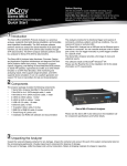
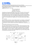
System ISR's
System Tasks
RTX Kernel
Hardware
User Tasks
User ISR's
Figure 1: Overview
The first item is also referred to as a
requirement for guaranteed response
times, also designated as "real-time".
The second item designates the typical
situation of multi-program operation
(multiprogramming, multi-tasking). In
this case, the individual tasks are
organized as independent computer
processes (normally designated as a
"task").
The RTX-51/251 Real-Time
Multitasking Executive contains the
functions to solve these types of
problem definitions in a simple and
effective way with all processors of the
8051/MCS 251 processor family.
The sequence control required for simple applications could, of course, be
implemented by the user himself. This, however, is not very efficient, since a large
part of the functions which a multitasking executive already offers would have to
be re-implemented.
Advantages in using a Real-Time Multitasking Executive:
n
A program can be more easily implemented, tested and maintained by breaking
down the problem to be solved into individual, easily comprehensible tasks.
n
The modular approach allows individual tasks to be used in other projects.
n
Since the real-time and multitasking problems which occur are already solved
the time required for creating programs and testing is considerably reduced.
1
2
Overview
Advantages of RTX-51/251 are:
1
n
Simple use of RTX-51/251 by integration in the Keil C51/C251 development
system.
n
Complete support of all C51/C251 features such as floating-point operations,
re-entrant functions and interrupt functions.
n
User-friendly configuration of RTX-51/251 for all members of the 8051/MCS
251 family.
n
Flexibility - only requires a few system resources and can also be applied for
time-critical applications.
Summary of the Major System Features
Tasks
RTX-51 (see section below for RTX-251) recognizes two classes of tasks:
n
Fast tasks with especially short responses and interrupt times. Each fast task
uses an individual register bank of the 8051 and contains its own stack area.
RTX-51 supports a maximum of three fast tasks active at a time.
n
Standard tasks that require somewhat more time for the task switching,
therefore less internal memory than the fast tasks. All standard tasks share a
register bank and a stack area; during a task change the current contents of
registers and the stack are stored in the external RAM. RTX-51 supports a
maximum of 16 standard tasks active at a time.
RTX-251 recognizes two classes of tasks:
n
Fast tasks with especially short response and interrupt times. Fast tasks use
context storage located in on-chip RAM for fastest access. RTX-251 supports
a maximum of 16 tasks of fast or standard type active at a time. A lower limit
may be set for fast tasks by the amount of available on-chip RAM.
n
Standard tasks require somewhat more time for the task switching, because
their context storage is located in slower external RAM. RTX-251 supports a
maximum of 16 tasks of fast or standard type active at a time.
RTX-51 / RTX-251
3
RTX-51/251 tasks are declared as parameterless C functions with the attribute
"_task_".
Task Communication and Synchronisation
RTX-51/251 provides two mechanisms so that the individual tasks can
communicate with each other and synchronize tasks which normally execute
independent of one another:
n
Signals are the fastest form of task synchronisation. No actual information is
exchanged - only a stimulus is activated for a task.
n
Messages are exchanged via so-called mailboxes. Mailboxes allow the
buffered exchange of data. Tasks can be entered in queues for these in order to
wait for a message to be received. The individual messages are managed by
the mailbox according to the FIFO principle (First-In, First-Out). If several
tasks are waiting for a message to be received, the task which is waiting the
longest (first in the queue) receives the message.
n
Semaphores are simple protocol mechanisms that share common resources
without access conflicts. By use of token's resources may be managed in such
a way that only one task at a time is allowed to use them. If more than one task
requests access to a resource, then the first task will be granted access, while
the second task is put on a waiting list until the first task finishes its operations
on this resource.
Task Switching
RTX-51/251 contains an event-driven task switching mechanism that switches
tasks according to their priority (preemptive multitasking). An additional task
switching mechanism which switches according to the time-slice mode can be
optionally used (round-robin scheduling).
RTX-51/251 recognizes four priority levels; priorities 0, 1 and 2 can be assigned
to standard tasks. Priority 3 is reserved for fast tasks.
The individual tasks can wait for various events to occur without requiring
processor time (no processor burdening). Events can be characterized as the
receipt of messages, signals, interrupts and time-outs, or a combination of these.
Three wait forms are supported:
n
Normal: the WAITING (BLOCKED) task can be blocked for an arbitrary
amount of time until the corresponding event occurs.
1
4
1
Overview
n
Conditional: the waiting task is never blocked, the task can recognize if the
corresponding event existed by evaluating the return value.
n
With time-out: the task is blocked for a certain time if the corresponding event
does not occur.
Interrupt System
RTX-51/251 performs task synchronisation for external events by means of the
interrupt system. Two types of interrupt processing are basically supported in this
case:
1. C51/C251 Interrupt Functions
Interrupts are processed by C51/C251 interrupt functions.
2. Task Interrupts
Interrupts are processed by fast or standard tasks of RTX-51/251.
The methods of interrupt processing can be selected depending on the application.
The individual methods can also be combined in an application.
System Clock
The RTX-51/251 system clock is based on hardware Timer 0 or 1 (can be
configured) of the 8051/MCS 251 processor. It supplies the basic pulse (clock
frequency) required for the time-outs and for the round-robin scheduling.
Operating Resources
RTX-51 (see section below for RTX-251) requires the following 8051 system
resources:
n
CODE Memory:
Approx. 6 to 8 Kbytes, depending on the function scope used.
n
Internal (DATA and IDATA) RAM:
40 to 46 bytes for system data (depending on the selected processor type).
20 to 200 bytes for the stack (can be configured by the user).
RTX-51 / RTX-251
5
Register bank 0 for standard tasks; register banks 1, 2 and 3 for fast tasks or
C51 interrupt functions.
1
n
External (XDATA) RAM:
Minimal 450 bytes.
n
Timer 0 or 1 for the system clock (can be configured by the user).
RTX-251 (see section above for RTX-51) requires the following MCS 251 system
resources:
n
CODE Memory:
Approx. 3 to 7 Kbytes, depending on the function scope used.
n
Internal (DATA and IDATA) RAM:
28 to 32 bytes for system data (depending on the selected processor type).
n
External (EDATA) RAM:
32 bytes for system data.
64 bytes up (max 64 Kbytes) for task system and reentrant stack data and
context storage.
n
External (XDATA) RAM:
Minimal 450 bytes.
n
Timer 0 or 1 for the system clock (can be configured by the user).
Program Example
The following simplified example illustrates the basic design of a RTX-51/251
application and the procedure for compiling and linking:
Example Program for a Simplified RTX-51/251
Application
#pragma large
#include "rtx51.h"
#define PRODUCER_NBR
#define CONSUMER_NBR
0
1
/*
/*
/*
/*
RTX-51 definitions */
NOTE: use rtx251.h for RTX-251
*/
Task number for the producer task */
Task number for the consumer task */
void producer_task (void) _task_ PRODUCER_NBR
{
unsigned int send_mes;
6
Overview
os_create_task (CONSUMER_NBR); /* Create the consumer task */
send_mes = 1;
for (;;) {
/* end-less loop */
/* Send actual value of "send_mes" to the mailbox 0 */
/* If the mailbox is full, wait until there is room */
/* for the message
*/
os_send_message (0, send_mes, 0xff);
send_mes++;
}
1
}
void consumer_task (void) _task_ CONSUMER_NBR _priority_ 1
{
unsigned int rec_mes;
for (;;) {
/* Read from the mailbox 0 to the variable "rec_mes" */
/* Wait for a message if the mailbox is empty
*/
os_wait (K_MBX+0, 0xff, &rec_mes);
/*
... Perform some calculations with "rec_mes"
*/
}
}
void main (void)
{
/* Initialize the system and start the producer task */
os_start_system (PRODUCER_NBR);
}
Compiling and Linking the Program
The most convenient way is to use µVision-51/251 for this purpose. A project
definition file named SAMPLE.PRJ contains all required settings and
automatically identifies all required files. Use ‘Open project’from the ‘Project’
menu to select this file. SAMPLE.PRJ can be found in the sub-directory RTX51
(for RTX-51) or RTX251 (for RTX-251) in the C51/C251 tools directory.
By use of the ‘Make: Build project’selection out of the ‘Project’menu the sample
program is compiled and linked in one step.
RTX-51 / RTX-251
7
Extract from the MAP file generated by
BL51/L251
BL51/L251 generates a task list which lists all tasks defined in the system along
with their identification number, the defined priority and the register bank used
RTX-51:
MS-DOS BL51 BANKED LINKER/LOCATER V3.11, INVOKED BY:
BL51.EXE SAMPLE.OBJ, RTXCONF.OBJ RTX51
MEMORY MODEL: LARGE
INPUT MODULES INCLUDED:
SAMPLE.OBJ (SAMPLE)
RTXCONF.OBJ (?RTX?CONFIGURATION)
C:\C51\LIB\RTX51.LIB (RTXINIT)
C:\C51\LIB\RTX51.LIB (RTXDATA)
C:\C51\LIB\RTX51.LIB (RTXCLK)
C:\C51\LIB\RTX51.LIB (RTXCREA)
C:\C51\LIB\RTX51.LIB (RTXINT)
C:\C51\LIB\RTX51.LIB (RTXWAIT)
C:\C51\LIB\RTX51.LIB (RTXSEND)
C:\C51\LIB\RTX51.LIB (RTX51_LIB____VERSION_0V500)
C:\C51\LIB\RTX51.LIB (RTXBLOCK)
C:\C51\LIB\RTX51.LIB (RTXDISP)
C:\C51\LIB\RTX51.LIB (RTXQUOP)
C:\C51\LIB\RTX51.LIB (RTXIHAND)
C:\C51\LIB\RTX51.LIB (RTXINS)
C:\C51\LIB\RTX51.LIB (RTX2C51)
C:\C51\LIB\C51L.LIB (?C_STARTUP)
TASK TABLE OF MODULE:
SAMPLE (SAMPLE)
TASKID PRIORITY REG-BANK
SEGMENT NAME
-----------------------------------------------------0
0
0
?PR?PRODUCER_TASK?SAMPLE
1
1
0
?PR?CONSUMER_TASK?SAMPLE
RTX-251:
DOS LINKER/LOCATER L251 V1.10, INVOKED BY:
C:\C251\BIN\L251.EXE SAMPLE.OBJ, RTXCONF.OBJ RTX251
CPU MODE:
BINARY MODE
INTR FRAME:
4 BYTES SAVED ON INTERRUPT
MEMORY MODEL: LARGE
INPUT MODULES INCLUDED:
SAMPLE.OBJ (SAMPLE)
COMMENT TYPE 0: C251 V1.10
1
8
1
Overview
RTXCONF.OBJ (?RTX?CONFIGURATION)
COMMENT TYPE 0: A251 V1.10
C:\C251\LIB\RTX251BD.LIB (RTXINIT)
COMMENT TYPE 0: A251 V1.10
C:\C251\LIB\RTX251BD.LIB (RTXDATA)
COMMENT TYPE 0: A251 V1.10
C:\C251\LIB\RTX251BD.LIB (RTXCLK)
COMMENT TYPE 0: A251 V1.10
C:\C251\LIB\RTX251BD.LIB (RTXSNDM)
COMMENT TYPE 0: A251 V1.10
C:\C251\LIB\RTX251BD.LIB (RTXCREA)
COMMENT TYPE 0: A251 V1.10
C:\C251\LIB\RTX251BD.LIB (RTXINT)
COMMENT TYPE 0: A251 V1.10
C:\C251\LIB\RTX251BD.LIB (RTXWAIT)
COMMENT TYPE 0: A251 V1.10
C:\C251\LIB\RTX251BD.LIB (RTXIHNDM)
COMMENT TYPE 0: A251 V1.10
C:\C251\LIB\RTX251BD.LIB (RTX251_LIB____VERSION_0V100)
COMMENT TYPE 0: A251 V1.10
C:\C251\LIB\RTX251BD.LIB (RTXBLOCK)
COMMENT TYPE 0: A251 V1.10
C:\C251\LIB\RTX251BD.LIB (RTXDISP)
COMMENT TYPE 0: A251 V1.10
C:\C251\LIB\RTX251BD.LIB (RTXQUOP)
COMMENT TYPE 0: A251 V1.10
C:\C251\LIB\RTX251BD.LIB (RTXIHNDS)
COMMENT TYPE 0: A251 V1.10
C:\C251\LIB\RTX251BD.LIB (RTXINS)
COMMENT TYPE 0: A251 V1.10
C:\C251\LIB\C251BL.LIB (?C_START)
COMMENT TYPE 0: A251 V1.10
C:\C251\LIB\C251BL.LIB (?C_INIT)
COMMENT TYPE 0: A251 V1.10
TASK TABLE OF MODULE:
SAMPLE (SAMPLE)
TASKID PRIORITY SEGMENT NAME
------------------------------------------0
0
?PR?PRODUCER_TASK?SAMPLE
1
1
?PR?CONSUMER_TASK?SAMPLE
Debugging the Program
The dScope debugger is started automatically upon completion of the link step. A
predefined dScope initialization file (SAMPLE.INI) is used to set breakpoints
inside of the two tasks and to define two watch variables.
The application code and an include file named DBG_RTX.INC are loaded. This
file contains declarations of dScope macros to support debugging of RTX51/251 code. The defined macros may be called as follows:
RTX-51 / RTX-251
n
9
With the key <F3> a table of all declared tasks may be displayed. It shows
some important information about them and the associated task states.
1
ID
n
Task number, as defined in the task-declaration.
Start
Task start address.
Prio
Task priority.
State
Actual task state.
Blocked for Event Defines for which event the task is blocked
(the task is waiting for).
Event codes used here are:
MSG:
wait for message (mailbox read)
INT:
wait for interrupt
SIG:
wait for signal
TMO:
wait for time-out
WRITEMAILBOX: wait until enough space in message
list of mailbox (mailbox write)
TKN:
wait for a token (from a semaphore)
Mbx/Sem: When the task is blocked for a
mailbox read/write, then this field
shows the mailbox number [0..7].
When the task is blocked for a
semaphore, then this field shows the
semaphore number [8..15].
Timer:
When the task is blocked for a timeout, then this field shows the
remaining number of system ticks to
time-out
Signal:
State of task signal flag (1=set,
0=reset)
With the key <F4> a list of all pre-defined mailboxes may be displayed.
10
Overview
1
Mbx
Msg
Read
Write
Messages
n
Mailbox number [0..7].
Number of messages in this mailbox.
Number of tasks which are blocked for reading a
message.
Number of task which are blocked for writing a
message.
Shows the messages contained in the mailbox.
With the key <F5> a list of all pre-defined semaphores may be displayed.
Sem
Tkn
Wait
Semaphore number [8..15].
State of token flag (1=token available; 0=else).
Number of tasks which are blocked for a token.
RTX-51 / RTX-251
11
Chapter 2. Installation
This chapter explains how to setup an operating environment and how to install
the software on your hard disk. Before starting the installation program, you must
do the following:
n
Verify that your computer system meets the minimum requirements.
n
Make a copy of the installation diskette for backup purposes.
Software Requirements
The following products are required to use RTX-51/251 together with Keil
C51/C251:
RTX-51:
n
C51 Compiler Version 5.02 or later
n
BL51 Linker for Code-Banking Version 3.52 or later
n
A51 Assembler Version 5.02 or later
n
RTX-51 Real-Time Executive Version 5.10 or later
RTX-251:
n
C251 Compiler Version 1.20 or later
n
L251 Linker Version 1.20 or later
n
A251 Assembler Version 1.20 or later
n
RTX-251 Real-Time Executive Version 1.0 or later
Backing Up Your Disks
We strongly suggest that you make a backup copy of the installation diskettes
using the DOS COPY or DISKCOPY commands. Then, use the backup disks to
install the software. Be sure to store the original disks in a safe place in case your
backups are lost or damaged.
2
12
Installation
Installing the Software
RTX-51/251 come with an installation program which allows easy installation
under MS-WINDOWS.
The following versions are supported:
2
n
MS-WINDOWS Version 3.1
n
MS-WINDOWS Version 3.11
n
MS-WINDOWS 95 or later
n
MS-WINDOWS NT Version 3.5 or later
To install RTX-51/RTX-251 ...
n
Insert the first product diskette into Drive A,
n
Select the Run... command from the File menu in the Program Manager,
n
Enter A:SETUP at the Command Line prompt,
n
Select the OK button
Then, follow the instructions displayed by the installation program.
NOTE:
n
Under Windows 95 or NT a slightly different procedure may be required.
n
The PK51/PK251 product must be installed before installing RTX-51/251.
Directory Structure
The installation program copies the RTX-51/251 files into sub-directories of the
PK51/PK251 base directories.
After creating the appropriate directory (if required), the installation program
copies the files into the sub-directories listed in the following table.
RTX-51 / RTX-251
Subdirectory
13
Description
...\BIN
Executable files (configuration utility).
...\RTX51
RTX-51 configuration files, sample applications.
...\RTX251
RTX-251 configuration files, sample applications.
...\CAN
CAN support
...\BITBUS
BITBUS support
...\INC
C include files.
...\LIB
Library files.
This table shows a complete installation. Your installation may vary depending on
the products you installed.
2
RTX-51 / RTX-251
15
Chapter 3. Programming Concepts
Task Management
The main function of tasks within a Real-Time Multitasking Executive is the timecritical processing of external or internal events. A priority can be assigned to the
individual tasks to differentiate between which are most important. In this case,
value 3 corresponds to the highest priority and value 0 corresponds to the lowest
priority.
RTX-51/251 always assigns the READY task with the highest priority to the
processor. This task only maintains control over the processor until another task
with a higher priority is ready for execution, or until the task itself surrenders the
processor again (preemptive multitasking).
If several READY tasks exist with the priority 0, a task switching can optionally
occur after completion of a time slice (round-robin scheduling).
Use the following guideline when assigning task priorities:
The application should work error free regardless task priorities. The
priorities only serve for time optimizing.
Task States
RTX-51/251 recognizes four task states:
READY
All tasks which can run are READY. One of
these tasks is the RUNNING (ACTIVE) task.
RUNNING (ACTIVE)
Task which is currently being executed by the
processor. Only one task (maximum) can be
in this state at a time.
BLOCKED (WAITING)
Task waits for an event.
SLEEPING
All tasks which were not started or which
have terminated themselves are in this state.
3
16
Programming Concepts
An event may be the reaching of a period of time, the sending of a message or
signal, or the occurrence of an interrupt. These types of events can lead to state
changes of the tasks involved; this, on the other hand, can produce a task
switching (task change, task switch).
The states "READY", "RUNNING" and "BLOCKED" are called active task
states, since they can only be accepted by tasks which were started by the user (see
system function "os_create_task"). "SLEEPING" is an inactive task state. It is
accepted from all tasks which were declared but still have not been started.
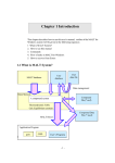
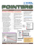
READY
3
Processor is released by
running task which starts
waiting for an event.
Highest priority ready
task starts running.
Event for task with higher
priority occurs. It preempts
running task, which is
inserted in list of ready
tasks.
Event for task occurs.
Task has lower priority than
running task: it is inserted in
list of ready tasks.
Event for task occurs, which has higher
priority than running task: it preempts it.
RUNNING
BLOCKED
Task starts waiting for an event. Processor is
assigned to next ready task.
Figure 2: Task States
The figure shows the three active task states and their interaction.
Task Switching
The RTX-51/251 system section which the processors assigns to the individual
tasks is referred to as the scheduler (also dispatcher).
The RTX-51/251 scheduler works according to the following rules:
RTX-51 / RTX-251
n
The task with the highest priority of all tasks in the READY state is executed.
n
If several tasks of the same priority are in the READY state, the task thay has
been ready the longest will be the next to execute.
n
Task switchings are only executed if the first rule would have been otherwise
violated (exception: round-robin scheduling).
17
These rules are strictly adhered to and never violated at any time. As soon as a
task yields a state change, RTX-51/251 checks whether a task change is necessary
based on the scheduling rules. Time-slice task change (round-robin scheduling)
are executed if the following conditions are satisfied:
n
Round-robin scheduling must be enabled (see configuration).
n
The RUNNING task has the priority of 0 and is currently not executing a
floating-point operation (see section "Floating-Point Operations", page 34).
n
At least one task with the priority zero must be in the READY state.
n
The last task change must have occurred after the selected system time interval
(see system function "os_set_slice"). The system time interval can be changed
dynamically during program execution.
The operating mode preferred by RTX-51/251 is the preemptive scheduling. If
desired by the user, the tasks with the priority zero can additionally be managed by
means of the round-robin scheduling.
Task Classes
RTX-51 (see section below for RTX-251) basically recognizes two classes of
tasks:
RTX-51 Fast Tasks
n
Contain especially short responses and interrupt disable times.
n
Contain a separate register bank and a separate stack area (register banks 1, 2
and 3).
n
Contain the highest task priority (priority 3) and can therefore interrupt
standard tasks.
n
All contain the same priority and can therefore not be mutually interrupted.
n
Can be interrupted by C51 interrupt functions.
3
18
Programming Concepts
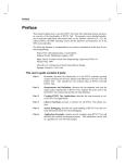
n
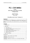
A maximum of three fast tasks can be active in the system.
Internal RAM
External RAM
Stack-Area for
Normal-Tasks
Stack-Area for
Fast-Task 3
Stack-Area for
Fast-Task 2
Stack-Area for
Fast-Task 1
3
Normal-Task
context
Registerbank 3 for
Fast-Task 3
Registerbank 2 for
Fast-Task 2
Registerbank 1 for
Fast-Task 1
Registerbank 0 for
Normal-Tasks
Normal-Task
context
Normal-Task
context
Figure 3: RTX-51 Task Classes and Memory Allocation
RTX-51 Standard Tasks
n
Require somewhat more time for the task switching compared to fast tasks.
n
Share a common register bank and a common stack area (register bank 0).
n
The current contents of registers and stack are stored in the external (XDATA)
memory during a task change.
n
Can be interrupted by fast tasks.
n
Can interrupt themselves mutually.
n
Can be interrupt by C51 interrupt functions.
n
A maximum 16 standard tasks can be active in the system.
RTX-51 / RTX-251
19
Each RTX-51 standard task contains a context area in the external memory.
During a task change with standard tasks, all required registers of the running task
and of the standard task stack are stored in the corresponding context area.
Afterwards, the registers and the standard task stack are reloaded from the context
area of the task to be started (swapping).
In the case of RTX-51 fast tasks, a task change occurs considerably faster than for
standard tasks, since each fast task has a separate register bank and a separate
stack area. During a task change to a fast task, only the active register bank and
the current stack pointer value must be changed.
RTX-251 (see section above for RTX-51) basically recognizes two classes of
tasks:
RTX-251 Fast Tasks
n
Contain short responses.
n
Contain a context save area located in on-chip RAM for fastest access.
n
Contain the highest task priority (priority 3) and can therefore interrupt
standard tasks.
n
All contain the same priority and can therefore not be mutually interrupted.
n
Can be interrupted by C251 interrupt functions.
n
The maximum number of fast tasks is limited by the maximum number of
active tasks in the system (16) and the available on-chip RAM for context
storage.
RTX-251 Standard Tasks
n
Require somewhat more time for the task switching compared to fast tasks.
n
Contain a context save area located in off-chip direct RAM.
n
Can be interrupted by fast tasks.
n
Can interrupt themselves mutually.
n
Can be interrupted by C251 interrupt functions.
n
A maximum 16 standard and fast tasks can be active in the system.
3
20
Programming Concepts
Each RTX-251 task contains a context area in the external memory. During a
task change all required registers of the running task are stored in the
corresponding context area. Afterwards, the registers are reloaded from the
context area of the task to be started (swapping). Each task has its own private
stack area inside of its context save area, therefore no stack swapping is required.
Additionally each task has its own private reentrant stack area as part of its
context save area, if any reentrant functions are declared in the system.
In the case of RTX-251 fast tasks, a task change occurs faster than for standard
tasks, since the context save areas of all fast tasks are automatically located in onchip RAM (faster access).
3
Task Declaration
C51/251 provides an extended function declaration for defining tasks.
A task is declared as follows:
void func (void) [model] _task_ <taskno> [_priority_ <prio>]
n
Tasks cannot return a value (return type "void").
n
No parameter values can be passed to tasks ("void" in parameter list).
n
<taskno> is a number assigned by the user in the range 0...255. Each task
must be assigned a unique number. This task number is required in RTX51/251 system function calls for identifying a task. A maximum of 256 tasks
can be defined. However, only 19 (RTX-51) or 16 (RTX-251) tasks can be
active at the same time.
Note: If the XDATA memory requirement of RTX-51/251 is to be
minimized, the tasks must be numbered sequentially beginning with the
number 0.
n
<prio> determines the priority of the task. The value 0 corresponds to the
lowest possible priority, value 3 corresponds to the highest possible priority.
The priorities define implicitly the task class:
- Standard tasks:
Priorities 0, 1 and 2
- Fast tasks:
Priority 3
If no priority is specified, RTX-51/251 uses the task priority 0.
RTX-51 / RTX-251
n
21
RTX-51 standard tasks must be compiled for register bank 0 which is the
default value of the C51 compiler. RTX-51 fast tasks must be compiled for
register banks 1, 2 or 3. This must be guaranteed using the directive "#pragma
REGISTERBANK (x)" (where x = 1, 2, 3). If this rule is violated, C51/BL51
generates an error message.
No special compiler directives are required for RTX-251 standard and fast
tasks.
Example 1: Standard task with task number 8 and priority 0
void example_1 (void) _task_ 8 _priority_ 0
or
void example_1 (void) _task_ 8
Example 2: Fast task with task number 134 and register bank 1 (Note:
registerbank declarations are required for RTX-51 only)
#pragma REGISTERBANK (1)
void example_2 (void) _task_ 134 _priority_ 3
n
Example of typical task layouts:
3
22
Programming Concepts
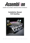
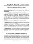
Task 1
Task 2
Initialisation
Initialisation
Function to be
performed
once for each
event.
Function to be
performed
once.
3
System call:
wait for event
System call:
delete itself
Figure 4: Typical Task Layouts
Task 1 shown in the figure above has to perform a certain action each time
an event occurs. Such an event may be a received message, a signal or a
time-out, just to mention a few.
After completing its action it will start to wait for a new event. In this way
the task will not consume time just waiting for the next event.
Task 2 shown in the figure above has to perform just one specific action. It
will delete itself after completing its job. Such a task may be, for example, a
self test, which has to be executed once at power-up. It is often desirable to
write such a self test routine as a separate task, than packing it in a routine.
Interrupt Management
The management and processing of hardware interrupts is one of the major jobs of
a Real-Time Multitasking Executive. RTX-51/251 provides various types of
interrupt handling. The usage depends on the application requirements.
RTX-51 / RTX-251
23
Methods for Interrupt Handling
RTX-51/251 provides two different methods for handling interrupts. One of the
two methods can be additionally divided into two sub-classes:
(1) C51/C251 Interrupt functions
(2) RTX-51/251 task interrupts:
Fast task interrupts
Standard task interrupts
Method (1) corresponds to the standard C51/C251 interrupt functions which can
even be used without RTX-51/251 (also referred to as ISR, Interrupt Service
Routine). When an interrupt occurs, a jump is made to the corresponding
interrupt function directly and independent of the currently running task. The
interrupt is processed outside of RTX-51/251 and therefore independent of the
task scheduling rules.
With method (2), a fast or standard task is used to handle an interrupt. As soon as
this interrupt occurs, the WAITING (BLOCKED) task is made READY and
started according to the task scheduling rules. This type of interrupt processing is
completely integrated in RTX-51/251. A hardware interrupt is handled identical
to the receipt of a message or a signal (normal event within RTX-51/251).
The possible methods to handle interrupts have specific advantages and
disadvantages, as described in greater detail in the following section. One of the
methods can be selected depending on the requirements of the interrupt source and
the application. The methods can be combined in any form within a program.
The following summary illustrates the special features of the individual methods
for handling interrupts:
Method
C51 Interrupt
Function (ISR)
Fast Task
Standard Task
Interrupt Response
Time
very fast
fast
slow (RTX-51),
medium (RTX-251)
Interrupts Disabled
During
very short,
system functions
critical system
functions,
other fast tasks
all system functions,
fast tasks
Interruptable With
-
ISR
ISR,
fast tasks,
standard tasks with
higher priority
3
24
Programming Concepts
System Resources
Used
many
(stack and usually extra
register bank)
many (RTX-51)
(stack and extra register
bank),
few (RTX-251)
(on-chip RAM for
context save)
few (RTX-51)
(stack and register bank
is shared with other
standard tasks),
few (RTX-251)
(off-chip RAM for
context save)
Interrupt Assignment
static
(only one interrupt
source per ISR)
dynamic
(multiple interrupt
sources per task
allowed)
dynamic
(multiple interrupt
sources per task
allowed)
Allowed RTX-51/251
System Calls
some special
all
all
There are considerable differences in timing between the different methods. Please
refer to timing specifications for more details.
3
The following points of emphasis deal with the features of the individual methods
for handling interrupts mentioned above:
n
C51/251 Interrupt Functions
Very sudden, periodically occurring interrupts without large coupling with the
rest of the system (only infrequent communication with RTX-51/251 tasks,
etc.).
Very important interrupts which must be served immediately independent of the
current system state.
n
Fast Task Interrupts
Important or periodic interrupts which must heavily communicate with the rest
of the system when they occur.
n
Standard Task Interrupts
Only seldom occurring interrupts which must not be served immediately.
RTX-51 shows considerable different response times for fast and standard tasks.
RTX-251 on the other side shows a superior performance based on the advanced
MCS 251 architecture. However the benefits in faster response times using fast
tasks compared with standard tasks may be small, especially if fast external RAM
is used.
RTX-51 / RTX-251
25
Handling of the 8051/MCS 251 Interrupt Enable
Register
RTX-51/251 must have sole control over the Interrupt Enable register of the
8051/MCS 251 in order to adhere to the dispatcher rules and guarantee error-free
execution of interrupt functions.
The INTERRUPT ENABLE registers of the 8051/MCS 251 are managed by
RTX-51/251 and must not be directly manipulated by the user!
RTX-51/251 controls the INTERRUPT ENABLE bits of the 8051/MCS 251
according to the following rules:
n
ISR interrupts can interrupt all tasks and system functions at any time. The
ISR interrupts are disabled only during a few very short system code
sequences.
n
The ISR interrupts can be disabled and enabled at the user's option using two
system functions (see "os_enable_isr" and "os_disable_isr").
n
Interrupt sources assigned to a task are only enabled if the task is actually
waiting for an interrupt to occur. This prevents unexpected interrupts from
occurring in the system.
n
If the running task is a RTX-51 fast task, all RTX-51 task interrupts are
disabled (not ISR interrupts, however). A relatively unimportant interrupt
therefore cannot interrupt the fast tasks.
RTX-251 uses a more relaxed rule: task interrupts are accepted anywhere
outside of system code, but a preemption takes place only, if the interrupt task
has a higher execution priority than the running task.
n
If the running task is a RTX-51 standard task or any RTX-251 task, it can be
interrupted by all interrupts which occur. If another RTX-51 standard task or
any RTX-251 task is waiting for one of these occurring interrupts, it is made
READY by RTX-51/251. However, it is only allocated to the processor if it
contains a higher priority than the currently running task (standard scheduling).
n
All RTX-51 standard task or any RTX-251 task interrupts are disabled during
the execution of system functions.
n
The system clock interrupt (hardware Timer 0 or 1) is handled the same as for
a fast task interrupt.
3
26
Programming Concepts
Handling of the 8051/MCS 251 Interrupt Priority
Register
The Interrupt Priority registers of the 8051/MCS 251 (not to be confused with the
software task priorities) are not influenced by RTX-51/251. Even in normal
operation (all interrupts at the same hardware priority), RTX-51/251 ensures that
ISR interrupts are handled with preference. If desired, however, the ISR interrupts
of the application can be set to a higher interrupt priority. RTX-51/251 does not
provide any operations for the management of the Interrupt Priority registers.
3
All RTX-51/251 task interrupts must run at the same hardware interrupt
priority! ISR interrupts may also run on an optional hardware interrupt
priority. An optimal ISR processing is not guaranteed, however, if task and
ISR interrupts are set to the same hardware priority.
Declaration of C51/C251 Interrupt Functions
Interrupt functions are declared as follows (see also C51/C251 documentation):
void func (void) [model] [reentrant] interrupt n [using n]
n
When interrupt functions are used, a difference must be made whether register
bank switching (using-attribute) is used or not.
n
With Register Bank Switching:
When entered, the interrupt function saves the registers ACC, B, DPH, DPL
and PSW (PSW1 with C251) to the stack of the interrupted task, when
necessary. Since not all registers are stored, the user must ensure that the
interrupt function does not use a register bank used by RTX-51/251. Register
bank 0 must also not be used (reason: it is always used by RTX-51 standard
tasks or any RTX-251 task and by the system clock). Register banks 1, 2 or 3
may only be used if they are not simultaneously being used by RTX-51 fast
tasks (RTX-251 fast tasks use register bank 0).
n
Without Register Bank Switching:
If no using-attribute is used, all registers required are saved on the stack. This
produces longer run times and increased stack requirement; for this purpose,
register banks used by RTX-51/251 may also be used.
RTX-51 / RTX-251
n
C51/C251 interrupt functions with using-attribute must never use register
bank 0 or one of the register banks used by a RTX-51 fast task.
n
C51/C251 interrupt functions without using-attribute can be used without
any restrictions (if enough stack is available).
27
Task Communication
The individual tasks within a real-time system can be dependent upon each other in
various ways. These can use common data, exchange information with each other,
or coordinate the activities for solving tasks.
RTX-51/251 provides the mailbox and signal concept for handling these types of
task-related jobs.
Signals
Signals represent the simplest and fastest form of task communication. These can
always be used when a pure task synchronisation is required without data
exchange.
Each active task contains its own signal flag with which the following operations
can be executed:
n
Wait for a signal
n
Send signal
n
Clear signal
The task number (see section section "Task Declaration", page 20) of the receiver
task is used for identifying the signals for the individual operations.
Wait for a Signal
Each task can wait for its signal flag (system function "os_wait"). It waits until its
signal flag is set by another task (system function "os_send_signal"). After a
signal is received, the waiting task clears its signal flag again and enters the task
state READY or RUNNING, depending on priority relationships.
3
28
Programming Concepts
If the signal flag is already set when the task calls the wait function (when the
signal flag was previously set by another task), then it immediately receives the
signal. The task does not first enter the WAIT state (BLOCKED).
The waiting time for a signal can be restricted. If the specified time has expired
without receiving the signal, the waiting task is made READY again with the
return status "time-out" (see system function "os_wait", page 65).
Send Signal
3
Each task and each interrupt function can set the signal flag of any other task
(send a signal to this task). Only one signal which has been sent can be stored per
task (signal flag). As long as a task has not received a signal, each additional
signal sent is lost.
Clear Signal
A task can clear the signal flag of any other task (even its own). This allows
defined signal states in the system at any time.
Mailboxes
By means of the mailbox concept, messages can be exchanged free of conflicts
between the individual tasks.
RTX-51/251 provides a fixed number of eight mailboxes. Messages can be
exchanged in words (2 bytes) via these mailboxes. In this case, a message can
represent the actual data to be transferred or the identification of a data buffer
(defined by the user). In comparison to the signals, mailboxes are not assigned a
fixed task, but can be freely used by all tasks and interrupt functions. These are
identified with a mailbox number.
Mailboxes allow the following operations:
n
Send a message
n
Read a message
RTX-51 / RTX-251
29
Mailbox Lists
Each mailbox internally consists of three wait lists. The user does not have direct
access to these lists. Knowledge of their functions is, however, an advantage for
understanding mailbox functions.
Wait lists can comprise the following states in operation:
State Description
Message List
Write Wait List
Read Wait List
No messages,
no wait tasks
empty
empty
empty
No messages,
tasks exist that want to read
empty
empty
not empty
Messages exist,
no wait tasks
not empty
empty
empty
Message list is full,
tasks exist that want to write
full
not empty
empty
The three lists do have the following functions:
(1) Message list
List of the messages written in the mailbox. These
comprise a maximum of eight messages.
(2) Write wait list Wait list for tasks which want to write a message in the
message list of the mailbox (maximum 16 tasks).
(3) Read wait list Wait list for tasks which want to read a message from the
message list of the mailbox (maximum 16 tasks).
All three lists are implemented as a FIFO queue (First-In, First-Out) without
priority assignment; i.e., when read, the task which waits the longest (first in the
queue) becomes the oldest messages in the mailbox.
Send a Message to a Mailbox
Each task can send a message to any arbitrary mailbox. In this case, the message
to be sent is copied in the message list. The sending task therefore has free access
to the message after the sending.
3
30
Programming Concepts
If the message list of the mailbox is already full during the sending, the task is
placed in the wait state (entered in the write wait list). It remains in the wait state
until another task fetches a message from the mailbox and, thus, provides space.
As an alternative, a time limit can also be specified for the sending after the
waiting is aborted (if the message could not be entered in the mailbox).
If the message list is not full when the sending occurs, the message is immediately
copied in the message list and the task must not wait.
Read a Message from a Mailbox
3
Each task can read a message from an arbitrary mailbox. If the message list of the
mailbox is currently empty (no
message available), the task is placed in the wait state (entered in the read wait
list).
It remains in the wait state until another task sends a message to the mailbox. As
an alternative, a time limit can also be specified for the reading after which the
waiting is to be aborted (if no message is available).
If the message is not empty when reading, then the reading task immediately
receives the message. It must not wait in this case.
Semaphores
By means of the semaphore concept, resources can be shared free of conflicts
between the individual tasks.
In a multi-tasking system there is often competition for resources. When several
tasks can use the same portion of memory, the same serial I/O channel or another
system resource, you have to find a way to keep the tasks out of each other's way.
The semaphore is a protocol mechanism, which is used primarily to control access
to shared resources (mutual exclusion).
A semaphore contains a token that your code acquires to continue execution. If
the resource is already in use, the requesting task is blocked until the token is
returned to the semaphore by its current owner.
RTX-51 / RTX-251
31
There are two types of semaphores: binary semaphores and counting semaphores.
As its name implies, a binary semaphore can only take two values: zero or one
(token is in or out). A counting semaphore, however, allows values between zero
and 65535.
RTX-51/251 provides a fixed number of eight semaphores of the binary type.
Semaphores allow the following operations:
n
Wait for token
n
Return (send) token
Wait for Token
A task requesting a resource controlled by a semaphore can obtain a token from
this semaphore by a wait operation (see system function "os_wait"). If a token is
available the task will continue its execution. Otherwise it will be blocked until
the token is available or an optional time limit is exceeded.
Send Token
After completing its operation on a resource a task will return the associated token
to the semaphore by a send function (see system function "os_send_token").
Dynamic Memory Management
Dynamic memory space is often desired in a multitasking system for generating
intermediate results or messages. The requesting and returning of individual
memory blocks should be possible within constant time limits in a real-time
system.
Memory management, which functions with memory blocks of variable size such
as the standard C functions "malloc()" and "free()," is less suitable for this reason.
RTX-51/251 uses a simple and effective algorithm, which functions with memory
blocks of a fixed size. All memory blocks of the same size are managed in a socalled memory pool. A maximum of 16 memory pools each a different block size
can be defined. A maximum of 255 memory blocks can be managed in each pool.
3
32
Programming Concepts
Generate Memory Pool
The application can generate a maximum of 16 memory pools with various block
sizes. The application must provide an XDATA area for this purpose. The pool
is stored and managed by RTX-51/251 in this area (see system function
"os_create_pool").
Request Memory Block from Pool
3
As soon as a pool has been generated, the application can request memory blocks.
The individual pools are identified by their block size in this case.
If an additional block is still free in the pool, RTX-51/251 supplies the start
address of this block to the application. If no block is free, a null pointer is
returned (see system function "os_get_block").
Return Memory Block to Pool
If the application no longer needs a requested memory block, it can be returned to
the pool for additional use (see system function "os_free_block").
Time Management
RTX-51/251 maintains an internal time counter, which measures the relative time
passed since system start. The physical source of this time base is a hardware
timer that generates an interrupt periodically. The time passed between these
interrupts is called a system time slice or a system tick.
This time base is used to support time dependent services, such as pause or timeout on a task wait.
Three time-related functions are supported:
n
Set system time slice
n
Delay a task
n
Cyclic task activation
RTX-51 / RTX-251
33
Set Time Slice
The period between the interrupts of the system timer sets the "granularity" of the
time base. The length of this period, also called a time slice, can be set by the
application in a wide range (see system function "os_set_slice").
Delay a Task
A task may be delayed for a selectable number of time slices. Upon calling this
system function the task will be blocked (sleep) until the specified number of
system ticks has passed (see system function "os_wait").
Cyclic Task Activation
For many real-time applications it is a requirement to do something on a regular
basis. A periodic task activation can be achieved by the RTX interval wait
function (see system function "os_wait"). The amount of time spent between two
execution periods of the same task is controlled, using os_wait, and is measured in
number of system ticks and may be set by the application.
Specific C51/C251 Support
Apart from the use of C51/C251 interrupt functions for fast processing of
hardware interrupts, RTX-51/251 also supports the most extensions of the
C51/C251 compiler.
The following sections provide an overview on the use of C51/C251 specific
features together with RTX-51/251.
C51/C251 Memory Models
A RTX-51/251 application can use all memory models supported by C51/C251
(SMALL, COMPACT, LARGE). However, the COMPACT model is normally
reserved for reentrant functions (see section "Reentrant Functions" below).
3
34
Programming Concepts
The selected memory model influences only the location of the application objects.
A part of the RTX-51/251 system variables is always stored in external (XDATA)
memory. All RTX-51/251 applications require external memory. Applications
without external memory are not possible.
Typical RTX-51/251 applications are normally implemented in the LARGE
model. Variables whose access is time critical can optionally be located in internal
RAM.
Reentrant Functions
3
Normal C51/C251 functions must not be simultaneously used by several tasks or
interrupt functions. These functions store their parameters and local data in static
memory segments. For this reason, this data is overwritten in the case of multiple
calls.
In order to solve this problem, C51/C251 provides reentrant functions (see
C51/C251 documentation). In the case of reentrant functions, the parameters and
local data are protected against multiple calls, since a separate stack is created for
them. RTX-51/251 supports the use of reentrant functions in the COMPACT
model. In this case, a separate reentrant stack whose size can be configured is
managed for each task. Interrupt functions use the reentrant stack of the
interrupted RTX-51/251 task.
n
RTX-51/251 only supports reentrant functions in the COMPACT model.
n
Each task contains a separate reentrant stack configurable in size.
n
Reentrant functions may be used in combination with non-reentrant
functions of the SMALL and LARGE models. Simultaneous use of
reentrant functions and non-reentrant functions is not allowed in the
COMPACT model!
Floating-Point Operations
The following section is intended for users of C51 versions older than V5.0. No
special restrictions apply for other C51 and C251 users !
In principle, RTX-51 tasks can execute all types of operations with floating-point
numbers. Since the C51 floating-point library is not implemented as reentrant
(DK/PK51 versions older than V5.0), a running operation must not be interrupted
RTX-51 / RTX-251
35
by another operation. In order to guarantee this, certain precautionary measures
must be assured.
No restrictions apply in the use of floating-point operations in the following two
cases:
n
Only one task (with optional priority) in the system executes floating-point
operations. Since no other task executes floating-point operations, a running
operation cannot be interrupted by another.
n
Only tasks with the priority 0 execute floating-point operations. If no roundrobin scheduling is used, no problems occur since the tasks cannot mutually
interrupt. When the round-robin scheduling is used, the task change during
floating-point operations is delayed up to the end of the operation (see
scheduling rules).
If several tasks assigned to different priorities use floating-point operations, the
standard C51 functions "fpsave" and "fprestore" must be used (see C51
documentation). In this case, the present state of an interrupted floating-point
operation must be stored with "fpsave" prior to floating-point operations. After
the operation, the state must be restored again with "fprestore" (same as using
floating-point operations in interrupt functions for C51 programs without RTX51). If “fpsave“ is called, then no RTX function is to be called until the function
“fprestore“ is executed (i.e. no RTX functions are allowed between “fpsave“ and
“fprestore“).
n
The use of floating-point operations is unproblematic only in one task or
exclusively in tasks with priority 0 (also with round-robin scheduling).
n
In all other cases, the standard C51 functions "fpsave" and "fprestore"
must be used. If “fpsave“ is called, then no RTX function call is allowed
unless “fprestore“ is executed.
Use of the C51/C251 Runtime Library
No restrictions apply for all standard library functions which are reentrant (see
C51/C251 documentation).
In regard to the small number of functions which are not reentrant, the user must
ensure that these are not simultaneously used by several tasks.
3
36
Programming Concepts
Register Bank Default
RTX-51 (see section below for RTX-251) assigns register bank 0 to all standard
tasks. Fast tasks receive register banks 1, 2 or 3 (selectable with the "#pragma
REGISTERBANK (x)" directive).
During a task change, RTX-51 automatically selects the currently required register
bank.
3
RTX-51 tasks and functions used by it must not be provided with the usingattribute (RTX-51 generates the register bank switching). The using-attribute
is only permissible for C51 interrupt functions.
RTX-251 makes use of the MCS 251 register file with register bank 0 selected for
all tasks. C251 interrupt functions may therefore use register banks 1, 2 and 3
freely.
Use of the C51 Special Library
C51 contains a special library for supporting the arithmetic unit and multiple data
pointers of some 8051 derivatives (80C517/537, DALLAS 80C320 and some
AMD chips).
The arithmetic unit can be used along with RTX-51. Note, however, that these
functions are not interrupt capable. For this reason, only one task or only tasks
with the priority 0 may use the arithmetic unit.
Multiple data pointers are not supported by RTX-51. If special library is to be
used, the option MOD517(NODP8) must be used. There is only one way to take
advantage of multiple data pointers, when running RTX-51: sections using
multiple data pointers must be globally protected against interrupts. Solely under
this condition the option MOD517 (or MODAMD) is acceptable.
The C51 special library uses multiple data pointers to speed up the functions
‘memcpy’, ‘memmove’, ‘memcmp’, ‘strcpy’and ‘strcmp’. If locking out of
interrupts is not a problem concerning the interrupt response time, then a sequence
like shown below is acceptable with RTX-51:
Example for Siemens 80C517(A)/537(A):
RTX-51 / RTX-251
37
unsigned int oldbuf[100];
unsigned int newbuf[100];
/* Enable usage of multiple data pointers */
$pragma MOD517
...
/* Disable interrupts globally */
EA = 0;
/* Copy data using multiple data pointers */
memcpy (newbuf, oldbuf, sizeof(newbuf));
/* Re-enable interrupts globally */
EA = 1;
/* Disable usage of multiple data pointers */
$pragma NOMOD517
Example for Dallas 80C320 and (some) AMD chips:
unsigned int oldbuf[100];
unsigned int newbuf[100];
/* Enable usage of multiple data pointers */
$pragma MODAMD (DP2)
...
/* Disable interrupts globally */
EA = 0;
/* Copy data using multiple data pointers */
memcpy (newbuf, oldbuf, sizeof(newbuf));
/* Re-enable interrupts globally */
EA = 1;
/* Disable usage of multiple data pointers */
$pragma NOMODAMD
Code Bankswitching
RTX-51 is fully compatible with the code banking scheme implemented by BL51
(version X2.04 or above). RTX-251 does not support code bank switching, since
code size may exceed 64 Kbytes in any case.
Building of a banked system requires the following steps (RTX-51 only):
n
Adapt the file L51_BANK.A51 to your requirements (see BL51
documentation).
n
Set the symbol ?RTX_BANKSWITCHING in RTXSETUP.DCL to 1.
3
38
Programming Concepts
n
Link the system as described in the BL51 documentation. All defined banks
can be used freely by the RTX-51 tasks.
n
The following code sections are automatically located in the common area:
RTX-51 system functions,
Reset and interrupt vectors
Code constants,
C51 interrupt functions,
Bank switch jump table,
Intrinsic C51 run-time library functions
Stack usage with code bankswitching:
3
n
Add 3 Bytes to each fast task stack for the bankswitch handling.
n
Standard tasks use no extra stack space for the bankswitching.
RTX-51 / RTX-251
39
Chapter 4. Programmer’s Reference
RTX-51/251 and the application built on it are linked with each other via a
C51/C251 compatible procedural interface. This interface provides all functions
for managing tasks, for task communication, and for all other services.
All RTX-51/251 system functions are reentrant and are implemented independent
of the register bank used.
This chapter contains an extensive description of all RTX-51/251 system
functions. Each of the following descriptions covers:
n
Function of the call
n
Declaration in C51/C251 (like contained in RTX51.H/RTX251.H)
n
Explanation of the parameters
n
Explanation of the return value
n
Call example
n
Cross reference to other calls
The function descriptions are contained in normal print; examples are each printed
in a different font.
Name Conventions
The name of the respective system function describes its type of use:
n
System functions whose name begins with "os_" may be used solely by
RTX-51/251 tasks.
n
System calls whose name begins with "isr_" may be used solely by
C51/C251 interrupt functions.
n
System calls whose name begins with "oi_" may be used by RTX-51/251
tasks and by C51/C251 interrupt functions, as well.
4
40
Programmer’s Reference
Return Values
Each system function returns an execution status as a return value. This provides
information whether the function could be executed successfully. Other status
information is passed to the caller in the same way. In the description of the
individual system functions, the return values currently possible are explained
including their meaning. The value 0 is returned after an error-free execution for
most of the system functions, when purposeful.
INCLUDE Files
The declarations for the RTX-51/251 system functions and all constant definitions
are contained in the files RTX51.H/RTX251.H. These declarations must be
specified at the beginning of the source program in an INCLUDE statement
(#include <rtx51.h>/#include <rtx251.h>).
4
Overview
Initialize and Start the System:
os_start_system (task_number)
Task Management:
os_create_task (task_number)
os_delete_task (task_number)
os_ running_task_id ()
Interrupt Management:
os_attach_interrupt (interrupt)
os_detach_interrupt (interrupt)
os_enable_isr (interrupt)
os_disable_isr (interrupt)
os_wait (event_selector, timeout, 0)
oi_set_int_masks (ien0, ien1, ien2)
oi_reset_int_masks (ien0, ien1, ien2)
Signal Functions:
os_send_signal (task_number)
os_wait (event_selector, timeout, 0)
RTX-51 / RTX-251
41
os_clear_signal (task_number)
isr_send_signal (task_number)
Message Functions:
os_send_message (mailbox, message, timeout)
os_wait (event_selector, timeout, *message)
isr_send_message (mailbox, message)
isr_recv_message (mailbox, *message)
Semaphore Functions:
os_send_token (semaphore)
os_wait (event_selector, timeout, 0)
Dynamic Memory Management:
os_create_pool (block_size, *memory, mem_size)
os_get_block (block_size)
os_free_block (block_size, *block)
Functions with the System Clock:
os_set_slice (timeslice)
os_wait (event_selector, timeout, 0)
Debug Functions:
os_check_tasks (*table)
os_check_task (task_number, *table)
os_check_mailboxes (*table)
os_check_mailbox (mailbox, *table)
os_check_semaphores (*table)
os_check_semaphore (semaphore, *table)
os_check_pool (block_size, *table)
4
42
Programmer’s Reference
Initialize and Start the System
Function Call Overview
A C51/C251 application typically will start its program execution by the main
function, after the C runtime environment has been set up. The startup of the run
time environment is handled by a C51/C251 library function, whose source code
can be seen in file STARTUP.A51/ STARTxxx.A51 (xxx: designating a special
version) or in file START251.A51, respectively.
The function "main" (called main program) contains the first user statement at its
beginning. It establishes the subroutine level 0 of every user application. The first
subroutine called by it will run on the subroutine level 1 and so on.
4
During its execution the following environment elements are used by the main
program (independent of use of RTX-51/251):
(1) Register bank 0
(2) System stack (top = ?STACK)
An application with RTX-51/251 will behave just like an application without
RTX-51/251 until the moment the "os_start_system" function is called. By use of
this function the normal C program will be transformed into a multitasking system.
The following steps will take place during "os_start_system":
- disable all interrupts
- clear the RTX system memory space
- initialization of RTX system tables
- initialization of the system clock hardware
- startup of the RTX system clock handler (system ISR)
- creation of the first user task
- initialization of the interrupt hardware
- enable interrupts
- start dispatcher
By "os_start_system" the first user task is created and the system clock handler
(system ISR) is started.
RTX-51 / RTX-251
43
Some considerations concerning the C51/C251 main function:
- The code part of the function "main", which is executed before
"os_start_system" is called, is executed like any C application without RTX51/251.
- The code part following the call of "os_start_system" is entered only when the
system function “os_start_system” fails. Otherwise the first user task will be
entered. There is no return from the function “os_start_system” in this case.
- Upon completion of "os_start_system" (when entering the first user task) the
interrupt system will be globally enabled (EA = 1). Unless the user disables it
explicitly, it will stay enabled almost all the time (also during system code of
RTX-51/251).
Available functions:
Function Name
Parameter
Description
os_start_system
unsigned char task_number
Identification of first user task
(number used in C51 task
declaration).
Initializes the system and starts the first
user task.
It is the first RTX function, which may be
called in a program.
4
44
Programmer’s Reference
os_start_system
Initialize RTX-51/251 and start the first task. This function is normally called in
the main program (main) of the C51/C251 application.
Prototype:
signed char os_start_system
(unsigned char task_number)
Parameter:
task_number identifies the task to be started first. The same
number is to be used which was used in the task declaration
(0..255).
Return Value:
If the initialization was successful, the first task begins to run.
Therefore, the program normally never returns from this call.
If the program does, however, return from this call, the
initialization was not successful:
4
NOT_OK (-1):
System could not be started. One of the following errors was
determined:
n
n
n
General error during starting
No task with this number was declared (wrong number)
The interrupt source which is normally assigned by the
system clock (Timer 0 or 1) is used by a C51/C251
interrupt function from the application. This state is not
allowed since the system clock would not function
correctly as a result.
See Also:
os_create_task
Example:
#include <rtx51.h>
/* Use rtx251.h for RTX-251 */
void first_task (void) _task_ 0 _priority_ 0 {
... task code
}
void main (void) {
if (os_start_system (0)) {
... error handling
}
}
RTX-51 / RTX-251
45
Task Management
Function Call Overview
Available functions are:
Function Name
Parameter
Description
os_create_task
unsigned char task_number
Number of task to be started (=
number used for task declaration).
Creates a task and includes it in
dispatching.
os_delete_task
unsigned char task_number
Number of task to be terminated.
Terminates a task.
os_running_task_id
(void)
Returns the number (identification) of the
running task.
4
46
Programmer’s Reference
os_create_task
Task function
The system operation, os_create_task, starts a function defined with the C51/C251
attribute "_task_" as a RTX-51/251 task. The task is assigned to the necessary
operating resources and is placed in the list of READY tasks.
Prototype:
signed char os_create_task (unsigned char task_number)
Parameter:
task_number identifies the task to be started. The same
number is to be used which was used in the task declaration
(0..255).
Return Value:
OK (0):
Task was started successfully (no error).
4
NOT_OK (-1):
Task could not be started. One of the following errors was
determined:
n
n
n
n
Register bank already assigned (error only possible when
starting RTX-51 fast tasks)
Maximum number of tasks already running (16 standard
tasks for RTX-51; 16 tasks of any type for RTX-251)
No task with this number was declared (wrong number).
Task already started.
See Also:
os_delete_task, os_check_tasks, os_check_task
Note:
If the new task has a higher priority than the running task, a
task switching occurs to the new task.
Example:
#include <rtx51.h>
/* Use rtx251.h for RTX-251 */
void count_task (void) _task_ 2 _priority_ 0 {
... task code
}
void first_task (void) _task_ 0 _priority_ 0 {
/* Function "count_task" is started as a task */
if (os_create_task (2)) {
... error handling
}
RTX-51 / RTX-251
47
void main (void) {
if (os_start_system (0)) {
... error handling
}
}
4
48
Programmer’s Reference
os_delete_task
Task function
The system operation, os_delete_task, stops a task and removes it from all system
lists. Releases all operating resources assigned to the task.
Prototype:
signed char os_delete_task (unsigned char task_number)
Parameter:
task_number identifies the task to be deleted. The same
number is to be used which was used in the task declaration.
Only tasks which were created with "os_create_task" can be
deleted. The running task can also stop itself.
Return Value:
4
OK (0):
Task was stopped successfully.
NOT_OK (-1):
The designated task was never created with "os_create_task".
See Also:
os_create_task, os_check_task, os_check_tasks
Note:
If the calling task specifies itself as a task to be deleted, a task
switching to the next READY task subsequently occurs.
Example:
#include <rtx51.h>
/* Use rtx251.h for RTX-251 */
void first_task (void) _task_ 0 _priority_ 0 {
... task code
}
void main (void) {
/* Task stopped itself */
if (os_delete_task (0)) {
... error handling
}
}
RTX-51 / RTX-251
49
os_running_task_id
Task function
The system operation, os_running_task_id, returns the task number of the running
task. This is the number which was used in the task declaration. Using this system
function, a C51/C251 function can, for example, determine the task from which it
was called.
Prototype:
signed char os_running_task_id (void)
Parameter:
None
Return Value:
The number of the task currently being executed by the
processor is returned. The task number corresponds to the
number used in the task declaration in this case (0..255).
See Also:
os_create_task, os_check_task, os_check_tasks
Note:
A C51/C251 function can use this system function to
determine from which task it was actually called.
Example:
#include <rtx51.h>
/* Use rtx251.h for RTX-251 */
void first_task (void) _task_ 0 _priority_ 0 {
unsigned char task_num;
... task code
/* Interrogate own task number */
task_num = os_running_task_id ();
/* task_num contains 0 */
...
}
void main (void) {
/* Task stopped itself */
if (os_delete_task (0)) {
... error handling
}
}
4
50
Programmer’s Reference
Interrupt Management
Function Call Overview
Available functions are:
Function Name
Parameter
Description
os_attach_interrupt
unsigned char interrupt_nbr
Vector number of interrupt source
to be attached.
Assigns an interrupt to the calling task.
os_detach_interrupt
unsigned char interrupt_nbr
Vector number of interrupt source
to be attached.
Reverses assignment of an interrupt
source to a task.
os_wait
unsigned int event_selector
Specification of requested wait
events. Any combination of wait
for interrupt, message/semaphore,
signal, time-out and interval is
allowed. Optionally identification
of mailbox or semaphore.
This is the general wait function of RTX51/251.
Any combination of events may be
selected. If one of the specified events
occurs, then task is made ready again
(i.e. waiting for events is terminated).
For details see separate chapter about
‘os_wait’!
4
unsigned int event_selector
Specification of requested wait
events. Any combination of wait
for interrupt, message/semaphore,
signal, time-out and interval is
allowed. Optionally identification
of mailbox or semaphore.
unsigned int timeout
Time-out in system ticks.
Insignificant if no wait for time-out
is specified.
unsigned int xdata *message
Address of buffer (2 bytes) in
XDATA space where received
message shall be stored.
Insignificant if no wait for message
is specified.
os_enable_isr
unsigned char interrupt_nbr
Identification (vector number) of
interrupt source the ISR waits for.
Enables the interrupt source assigned to
an ISR.
os_disable_isr
unsigned char interrupt_nbr
Identification (trap number) of
interrupt source the ISR waits for.
Disables the interrupt source assigned to
an ISR.
oi_set_int_masks
unsigned char ien0, ien1, ien2
Interrupt register masks containing
a 1 at each bit position to be
enabled.
Enable one or more interrupt(s) not
associated to RTX tasks. Modifies
physical registers and logical mirrors kept
by RTX.
RTX-51 / RTX-251
51
Function Name
Parameter
Description
oi_reset_int_masks
unsigned char ien0, ien1, ien2
Interrupt register masks containing
a 1 at each bit position to be
disabled.
Disable one or more interrupt(s) not
associated to RTX tasks. Modifies
physical registers and logical mirrors kept
by RTX.
4
52
Programmer’s Reference
os_attach_interrupt
Task function
The system call, os_attach_interrupt, dynamically assigns an interrupt source to
the calling task. Before wait is made for an interrupt using "os_wait", this must
first be assigned to the task. This assignment remains in force until it is canceled
with "os_detach_interrupt".
Each interrupt source can not be assigned to more than one task. However,
several interrupt sources can be assigned to a single task (a task can wait for
several interrupts to occur).
Using "os_attach_interrupt", the corresponding interrupt is still not enabled in the
processor hardware (INTERRUPT ENABLE register). All assigned interrupts are
enabled (see section "Handling of the 8051/MCS 251 Interrupt Enable Register",
page 25) only after the task waits for an interrupt to occur with "os_wait".
4
Prototype:
signed char os_attach_interrupt
(unsigned char interrupt)
Parameter:
interrupt designates the vector number of the desired
interrupt source. Permissible values are 0..31.
RTX-51/251 stores a corresponding interrupt vector at
address "8 * interrupt + 3".
The vector number which is permissible depends on the
microcontroller type used from the 8051/MCS 251 family.
RTX-51/251 checks whether the specified interrupt is
supported by the microcontroller used (see configuration).
The standard 8051 microcontroller supports the following
vector numbers:
0: External 0 interrupt
1: Timer/counter 0 interrupt (can be reserved for the system
clock)
2: External 1 interrupt
3: Timer/counter 1 interrupt (can be reserved for the system
clock)
RTX-51 / RTX-251
53
4: Serial port
Different processor versions of the 8051/MCS 251 family
may support additional interrupt sources (see literature of
chip manufacturer).
Return Value:
OK (0):
Function executed successfully.
NOT_OK (-1):
Function not executed, one of the following errors was
determined:
n
n
n
n
Vector number does not exist for this processor type.
The interrupt source requested was already assigned to
another task.
Interrupt is already used by a C51/C251 interrupt
function.
Interrupt is used by the system clock
See Also:
os_detach_interrupt, os_wait
Note:
More than one interrupt may be assigned to a particular task.
It is not allowed, however, to assign a particular interrupt
source to more than one task.
Example:
#include <rtx51.h>
/* Use rtx251.h for RTX-251 */
void count_task (void) _task_ 2 _priority_ 0 {
/* Assign external 0 interrupt to this task */
if (os_attach_interrupt (0)) {
... error handling
}
for (;;) {
/* Endless loop */
os_wait (K_INT, 0xff, 0); /* Wait for int. */
... task code
}
}
4
54
Programmer’s Reference
os_detach_interrupt
Task function
The system operation os_detach_interrupt, cancels the assignment of an interrupt
source to the calling task. The only interrupt sources that can be used are those
that were previously assigned to a task with "os_attach_interrupt".
Prototype:
signed char os_detach_interrupt
(unsigned char interrupt)
Parameter:
interrupt designates the vector number of the desired
interrupt source. Permissible values are 0..31.
RTX-51/251 stores a corresponding interrupt vector at
address "8 * interrupt + 3".
The vector number which is permissible depends on the
microcontroller type used from the 8051/MCS 251 family.
RTX-51/251 checks whether the specified interrupt is
supported by the microcontroller used (see configuration).
4
The standard 8051 microcontroller supports the following
vector numbers:
0: External 0 interrupt
1: Timer/counter 0 interrupt (can be reserved for the system
clock)
2: External 1 interrupt
3: Timer/counter 1 interrupt (can be reserved for the system
clock)
4: Serial port
Different processor versions of the 8051/MCS 251 family
may support additional interrupt sources (see literature of
chip manufacturer).
Return Value:
OK (0):
Function executed successfully.
RTX-51 / RTX-251
55
NOT_OK (-1):
Function not executed, one of the following errors was
determined:
n
n
Interrupt does not exist for this processor type.
Interrupt source requested is not assigned to the calling
task.
See Also:
os_attach_interrupt, os_wait
Note:
More than one interrupt may be assigned to a particular task.
It is not allowed, however, to assign a particular interrupt
source to more than one task.
Example:
#include <rtx51.h>
/* Use rtx251.h for RTX-251 */
void count_task (void) _task_ 2 _priority_ 0 {
/* Assign external 0 interrupt to this task */
if (os_attach_interrupt (0)) {
... error handling
}
for (;;) {
/* Endless loop */
os_wait (K_INT, 0xff, 0); /* Wait for int. */
... task code
...
/* After the int. processing has finished */
/* the assignment to this task is canceled */
if (os_detach_interrupt (3)) {
... error handling
}
}
}
4
56
Programmer’s Reference
os_enable_isr
Task function
The system operation, os_enable_isr, enables an interrupt source which is assigned
to a C51/C251 interrupt function (the assignment is determined in the interrupt
function definition, see section "Declaration of C51/C251 Interrupt Functions",
page 26). The interrupt must be enabled with this function in order for an
interrupt to trigger a C51/C251 interrupt function.
4
Prototype:
signed char os_enable_isr (unsigned char interrupt)
Parameter:
interrupt designates the vector number which the desired
C51/C251 interrupt function (Interrupt Service Routine, ISR)
is assigned to. Permissible values are 0..31.
C51/C251 stores a corresponding interrupt vector at address
"8 * interrupt + 3".
The vector number which is permissible depends on the
microcontroller type used from the 8051/MCS 251 family.
RTX-51/251 checks whether the specified interrupt is
supported by the microcontroller used (see configuration).
The standard 8051 microcontroller supports the following
vector numbers:
0: External 0 interrupt
1: Timer/counter 0 interrupt (can be reserved for the system
clock)
2: External 1 interrupt
3: Timer/counter 1 interrupt (can be reserved for the system
clock)
4: Serial port
Different processor versions of the 8051/MCS 251 family
may support additional interrupt sources (see literature of
chip manufacturer).
RTX-51 / RTX-251
Return Value:
57
OK (0):
Function was executed successfully
NOT_OK (-1):
Function not executed, one of the following errors was
determined:
n
n
Interrupt does not exist for this processor type.
No C51/C251 interrupt function exists for this vector
number.
See Also:
os_disable_isr
Example:
#include <rtx51.h>
/* Use rtx251.h for RTX-251 */
void fast_int (void) interrupt 7 using 1 {
/* C51/C251 int. function, waits for int. 7 */
/* Uses register bank 1
*/
... ISR code
}
void isr_manager (void) _task_ 4 _priority_ 1 {
/* Enable the interrupt with vector number 7 */
if os_enable_isr (7) {
... error handling
};
... task code
}
4
58
Programmer’s Reference
os_disable_isr
Task function
The system operation, os_disable_isr, disables an interrupt source assigned to a
C51/C251 interrupt function. This is used to temporarily inactivate an Interrupt
Service Routine (ISR).
Prototype:
signed char os_disable_isr (unsigned char interrupt)
Parameter:
interrupt designates the vector number which is assigned to
the desired C51/C251 interrupt function.
Permissible values are 0..31.
C51/C251 stores a corresponding interrupt vector at address
"8 * interrupt + 3".
The vector number which is permissible depends on the
microcontroller type used from the 8051/MCS 251 family.
RTX-51/251 checks whether the specified interrupt is
supported by the microcontroller used (see configuration).
4
The standard 8051 microcontroller supports the following
vector numbers:
0: External 0 interrupt
1: Timer/counter 0 interrupt (can be reserved for the system
clock)
2: External 1 interrupt
3: Timer/counter 1 interrupt (can be reserved for the system
clock)
4: Serial port
Different processor versions of the 8051/MCS 251 family
may support additional interrupt sources (see literature of
chip manufacturer).
Return Value:
OK (0):
Function was executed successfully.
RTX-51 / RTX-251
59
NOT_OK (-1):
Function not executed, one of the following errors was
determined:
n
n
Interrupt does not exist for this processor type.
No C51/C251 interrupt function exists for this vector
number.
See Also:
os_enable_isr
Example:
#include <rtx51.h>
/* Use rtx251.h for RTX-251 */
void fast_int (void) interrupt 7 using 1 {
/* C51/C251 int. function, waits for int. 7 */
/* Uses register bank 1
*/
... ISR code
}
void isr_manager (void) _task_ 4 _priority_ 1 {
/* Disable the interrupt with vector number 7 */
if os_disable_isr (7) {
... error handling
};
... task code
}
4
60
Programmer’s Reference
oi_set_int_masks
Task/ISR function
The system operation, oi_set_int_masks, sets one or more interrupt mask bits
immediately.
Since this function is dedicated to non standard cases it does not contain any
parameter checks.
Its use should be restricted to the following special cases:
−
to manipulate special bits, which are part of the interrupt enable registers.
(Example: watchdog control bits on 80C517/80C537 processors)
−
to modify interrupt enable bits from inside a C51/C251 interrupt function.
Not to be used for interrupt sources attached to RTX-51/251 tasks !
4
Prototype:
signed char oi_set_int_masks
(unsigned char ien0,
unsigned char ien1,
unsigned char ien2)
Parameter:
ien0, ien1, ien2 represent the bit masks of the interrupt enable
registers.
An interrupt source to be enabled explicitly has to set its
associated bit. For this parameter the same bit layout is used
as defined for the corresponding interrupt enable registers.
Depending on the processor type used zero or more of these
masks are insignificant. Use as follows:
ien0, ien1, ien2 for processors with 3 interrupt enable
registers.
ien0, ien1 for processors with 2 interrupt enable registers
(ien2 is insignificant)
ien0 for processors with 1 interrupt enable register (ien1 and
ien2 are insignificant).
Return Value:
OK (0):
Function was executed successfully. This return code is
always used as this function does no parameter checking at all
!
See Also:
oi_reset_int_masks
RTX-51 / RTX-251
61
Note:
Never change an interrupt enable bit whose interrupt source is
attached to a RTX-51/251 task.
This function can not modify the global interrupt enable bit
(EA-bit). This bit can be manipulated by the user directly.
Example:
#include <rtx51.h>
/* Use rtx251.h for RTX-251 */
void isr_manager (void) _task_ 4 _priority_ 1 {
/* Enable the serial interrupt of a 8051/ */
/* MCS 251 processor */
oi_set_int_masks (0x10, 0, 0);
... task code
}
4
62
Programmer’s Reference
oi_reset_int_masks
Task/ISR function
The system operation, oi_reset_int_masks, resets one or more interrupt mask bits
immediately.
Since this function is dedicated to non standard cases it does not contain any
parameter checks.
Its use should be restricted to the following special cases:
−
to manipulate special bits, which are part of the interrupt enable registers.
(Example: watchdog control bits on 80C517/80C537 processors)
−
to modify interrupt enable bits from inside a C51/C251 interrupt function.
Not to be used for interrupt sources attached to RTX-51/251 tasks !
4
Prototype:
signed char oi_reset_int_masks
(unsigned char ien0,
unsigned char ien1,
unsigned char ien2)
Parameter:
ien0, ien1, ien2 represent the bit masks of the interrupt enable
registers.
An interrupt source to be disabled explicitly has to set its
associated bit. For this parameter the same bit layout is used
as defined for the corresponding interrupt enable registers.
Depending on the processor type used zero or more of these
masks are insignificant. Use as follows:
ien0, ien1, ien2 for processors with 3 interrupt enable
registers.
ien0, ien1 for processors with 2 interrupt enable registers
(ien2 is insignificant)
ien0 for processors with 1 interrupt enable register (ien1 and
ien2 are insignificant).
Return Value:
OK (0):
Function was executed successfully. This return code is
always used as this function does no parameter checking at all
!
See Also:
oi_set_int_masks
RTX-51 / RTX-251
63
Note:
Never change any interrupt enable bit whose interrupt source
is attached to a RTX-51/251 task.
This function can not modify the global interrupt enable bit
(EA-bit). This bit can be manipulated by the user directly.
Example:
#include <rtx51.h>
/* Use rtx251.h for RTX-251 */
void isr_manager (void) _task_ 4 _priority_ 1 {
/* Disable the serial int. of a 8051/ */
/* MCS 251 processor */
oi_reset_int_masks (0x10, 0, 0);
... task code
}
4
64
Programmer’s Reference
Wait Function
Function Call Overview
Function Name
Parameter
Description
os_wait
unsigned int event_selector
Specification of requested wait
events. Any combination of wait
for interrupt, message/semaphore,
signal, time-out and interval is
allowed. Optionally identification
of mailbox or semaphore.
This is the general wait function of RTX51/251.
Any combination of events may be
selected. If one of the specified events
occurs, then task is made ready again
(i.e. waiting for events is terminated).
unsigned int timeout
Time-out in system ticks.
Insignificant if no wait for time-out
is specified.
4
unsigned int xdata *message
Address of buffer (2 bytes) in
XDATA space where received
message shall be stored.
Insignificant if no wait for message
is specified.
RTX-51 / RTX-251
65
os_wait
Task function
This is the general RTX-51/251 wait function. All wait functions of tasks are
executed using this function.
"os_wait" can be used to wait for one or more events. Events can be any
combination of an interrupt, signal, interval, time-out or message/token arrived. If
one of the specified events occurs, the called task is made READY again (OR’ing
the individual events).
Prototype:
signed char os_wait
Parameter:
event_selector specifies the events which are to be waited
for. The value is calculated according to the following simple
equation:
event_selector =
(unsigned char event_selector,
unsigned char timer_ticks,
unsigned int xdata *message)
(event1) + (event2) + (event3) +
(event4) + (event5) + (mbxsem_nbr)
event1= K_MBX (10H)
event2= K_INT (20H)
event3= K_SIG (40H)
event4= K_TMO (80H)
event5= K_IVL (00H)
to wait for a message or a token
to wait for interrupt
to wait for signal
to wait for time-out
to wait for interval
mbxsem_nbr = 0..7
Selects the mailbox from which a message is to be received.
This specification is only necessary if the waiting for a
message/semaphore (K_MBX) was also specified.
Note: Simultaneous waiting on several mailboxes or
semaphores is not allowed.
mbxsem_nbr = 8..15
Selects the semaphore from which a token is to be received.
This specification is only necessary if the waiting for a
message/semaphore (K_MBX) was also specified.
4
66
Programmer’s Reference
Note: Simultaneous waiting on several semaphores or
mailboxes is not allowed.
Example 1: Wait for interrupt or signal.
event_selector = K_INT + K_SIG
Example 2: Wait for message from mailbox 3 or time-out
event_selector = K_MBX + K_TMO + 3
Example 3: Wait for interrupt or message from mailbox 1
event_selector = K_MBX + K_INT + 1
Example 4: Wait for interrupt or token from semaphore 9
event_selector = K_MBX + K_INT + 9
4
timer_ticks determines the number of system intervals to
occur until a time-out event occurs, if K_TMO was specified
(in ‘event_selector’).
Determines the length of interval, if K_IVL was specified (in
‘event_selector’).
Must be set to 0 (or 255) if no wait for time-out or interval
has been specified.
0 .. 254:
Number of system intervals for which the event should wait.
If the value 0 was specified, the system checks to see if one of
the other specified events has already occurred (interrupt
already pending, signal already set, etc.). If no other event
was specified, or if no other event occurred, the system
function returns to the time-out return value (TMO_EVENT).
Otherwise, the corresponding event value is returned.
255:
Endless waiting.
message is a variable (2 bytes) in the XDATA area where the
message that is read by the mailbox is to be stored. This
parameter is insignificant if no wait for a mailbox message
was specified (a null pointer can be specified).
RTX-51 / RTX-251
Return Value:
67
MSG_EVENT (1): A message was received from mailbox
and stored in "message".
INT_EVENT (2): An interrupt occurred.
SIG_EVENT (3): A signal was received.
TMO_EVENT (4): A time-out or interval end occurred.
SEM_EVENT (5) A token arrived from semaphore.
NOT_OK (-1):
Task wait list is full (more than 16 tasks
waiting on a mailbox/semaphore; this
error can only occur with the event
K_MBX).
See Also:
os_send_message, os_send_token, isr_send_message,
isr_recv-_message, os_check_mailboxes, os_check_mailbox,
os_set_slice
Note:
If C51/C251 operates with an optimization level larger than
OPTIMIZE(3), local variables can be kept in registers. The
function "os_wait" expects message variables in the XDATA
area, however. If an optimization level larger than three is
used, the local message variable should be provided with the
attribute "static". C51/C251 does not store these types of
variables in the registers.
If a wait for time-out is combined with a wait for interval,
then the wait for time-out supersedes. In this case only a wait
for time-out is done.
A wait for time-out is based on the actual system time, while
a wait for interval is based on the last wake-up time of the
calling task (thus establishing a regular interval). If there is
no last wake-up time stored for a task, then the actual time
will be used (this is the case when waiting for interval the first
time).
Waiting for a mailbox combined with waiting for a
semaphore is not supported. These two wait types are
mutually exclusive.
Example 1:
#include <rtx51.h>
/* Use rtx251.h for RTX-251 */
void delay_task (void) _task_ 54 _priority_ 2 {
for (;;) {
/* Wait only for Time-out */
os_wait (K_TMO, 100, 0);
/* The following functions are all */
4
68
Programmer’s Reference
/* executed 100 system cycles
....
....
*/
}
}
Example 2:
#include <rtx51.h>
/* Use rtx251.h for RTX-251 */
void count_task (void) _task_ 2 _priority_ 0 {
/* Assign external 0 interrupt to this task*/
if (os_attach_interrupt (0)) {
... error handling
}
for (;;) {
/* Endless loop
/* Wait for interrupt or time-out
if (os_wait(K_INT+K_TMO, 10, 0)
== TMO_EVENT){
/* If int. 0 does not occur within
/* 10 system cycles, then
/* perform this section
....
....
} else {
/* The int. occurred within
/* 10 system cycles
....
....
}
... task code
}
4
*/
*/
*/
*/
*/
*/
*/
}
Example 3:
#include <rtx51.h>
/* Use rtx251.h for RTX-251 */
void multiple_wait (void) _task_ 19 {
static unsigned int xdata mes;
.....
.....
switch (os_wait(K_MBX+K_TMO+K_SIG+2, 10, &data)){
case MSG_EVENT:
/* Message receipt from mbox 2 */
/* in "DATA"
*/
....
....
break;
case SIG_EVENT:
/* Signal receipt */
....
....
break;
RTX-51 / RTX-251
69
case TMO_EVENT:
/* No int. or message receipt within */
/* 10 system cycles --> time-out
*/
....
....
break;
}
}
4
70
Programmer’s Reference
Signal Functions
Function Call Overview
Available functions are:
4
Function Name
Parameter
Description
os_send_signal
unsigned char task_number
Identification (number) of signal
receiving task.
Send a signal to a task.
os_clear_signal
unsigned char task_number
Identification (number) of task,
whose signal shall be cleared.
Clear signal of a task.
isr_send_signal
unsigned char task_number
Identification (number) of signal
receiving task.
Send a signal to a task.
os_wait
unsigned int event_selector
Specification of requested wait
events. Any combination of wait for
interrupt, message/semaphore,
signal, time-out and interval is
allowed. Optionally identification of
mailbox or semaphore.
This is the general wait function of RTX51/251.
Any combination of events may be
selected. If one of the specified events
occurs, then task is made ready again
(i.e. waiting for events is terminated).
For details see separate chapter about
‘os_wait’!
unsigned int timeout
Time-out in system ticks.
Insignificant if no wait for time-out is
specified.
unsigned int xdata *message
Address of buffer (2 bytes) in
XDATA space where received
message shall be stored.
Insignificant if no wait for message
is specified.
RTX-51 / RTX-251
71
os_send_signal
Task function
The system operation, os_send_signal, sends a signal to another task. If the task is
already waiting for a signal, then it is made READY again by this. Otherwise, the
signal is stored in the signal flag of the addressed task.
Prototype:
signed char os_send_signal (unsigned char task_number)
Parameter:
task_number is the identification of the task to where a
signal is to be sent.
Return Value:
OK (0):
Signal was sent successfully.
NOT_OK (-1):
No signal was sent. The following exception occurred:
n
n
The specified task does not exist.
The signal flag was already set since the task still has not
finished processing (received) a previously sent signal.
See Also:
os_wait, isr_send_signal, os_clear_signal
Example:
#include <rtx51.h>
/* Use rtx251.h for RTX-251 */
void xyz_task (void) _task_ 89 _priority_ 0 {
... task code
/* Send signal to task 19 */
os_send_signal (19);
....
}
4
72
Programmer’s Reference
os_clear_signal
Task function
The system operation, os_clear_signal, clears the signal flag of a certain task; (i.e.,
a signal possibly stored for the task is cleared). This function is primarily intended
for creating defined output states.
4
Prototype:
signed char os_clear_signal (unsigned char task_number)
Parameter:
task_number is the identification of the task whose signal
flag state is to be cleared.
Return Value:
OK (0):
Signal flag was cleared successfully.
NOT_OK (-1):
Function was not executed. The specified task does not exist.
See Also:
os_wait, os_send_signal, isr_send_signal
Example:
#include <rtx51.h>
/* Use rtx251.h for RTX-251 */
void xyz_task (void) _task_ 89 _priority_ 0 {
...task code
/* Clear signal from task 19 */
os_clear_signal (19);
....
}
RTX-51 / RTX-251
73
isr_send_signal
ISR Function
A C51/C251 interrupt function sends a signal to a task. If this task is already
waiting for a signal, then it is made READY again by this. Otherwise, the signal
is stored in the signal flag of the addressed task.
Prototype:
signed char isr_send_signal
(unsigned char task_number)
Parameter:
task_number is the identification of the task to where a
signal is to be sent.
Return Value:
OK (0):
Signal was sent successfully.
NOT_OK (-1):
No signal was sent. The specified task does not exist.
See Also:
os_wait, os_send_signal, os_clear_signal
Example:
#include <rtx51.h>
/* Use rtx251.h for RTX-251 */
void fast_int (void) interrupt 7 using 1 {
/* C51/C251 int. function, wait for int. 7 */
/* Uses register bank 1
*/
/* If interrupt 7 occurs, the
/* ISR sends a signal to task 19
isr_send_signal (19);
}
*/
*/
4
74
Programmer’s Reference
Message Functions
Function Call Overview
Available functions are:
Function Name
Parameter
Description
os_send_message
unsigned char mailbox
Identification (number) of mailbox
a message shall be sent to.
Send a message to a mailbox. If
message list is full, then the task will wait
until enough space is available (a timelimit
may be chosen).
Unsigned int message
Message to be sent (2 byte value).
Unsigned int timeout
Timelimit for waiting in case the
message list is full.
4
isr_send_message
unsigned char mailbox
Identification (number) of mailbox
a message shall be sent to.
Send a message to a mailbox. If
message list is full at the moment, then
the message will be lost.
unsigned int message
Message to be sent (2 byte value).
isr_recv_message
unsigned char mailbox
Identification (number) of mailbox
a message shall be received from.
unsigned int xdata *message
Address of buffer (2 bytes) in
XDATA space where received
message shall be stored.
Receive a message from a mailbox, if any
is stored in it.
RTX-51 / RTX-251
75
Function Name
Parameter
Description
os_wait
unsigned int event_selector
Specification of requested wait
events. Any combination of wait
for interrupt, message/semaphore,
signal, time-out and interval is
allowed. Optionally identification
of mailbox or semaphore.
This is the general wait function of RTX51/251.
Any combination of events may be
selected. If one of the specified events
occurs, then task is made ready again
(i.e. waiting for events is terminated).
For details see separate chapter about
‘os_wait’!
unsigned int timeout
Time-out in system ticks.
Insignificant if no wait for time-out
is specified.
unsigned int xdata *message
Address of buffer (2 bytes) in
XDATA space where received
message shall be stored.
Insignificant if no wait for message
is specified.
4
76
Programmer’s Reference
os_send_message
Task function
The system operation, os_send_message, sends a message to a certain mailbox. A
message is a 2-byte value which can be defined by the user according to
requirements, either directly as a data value or as pointer to a data buffer.
If the message list of the mailbox is full, the calling task is blocked. The task is
made READY again only after another task receives a message (and therefore has
made space) or the selectable time limit has exceeded.
A mailbox can store a maximum of 8 messages. A maximum of 16 tasks can wait
at a full mailbox.
Prototype:
signed char os_send_message (unsigned char mailbox,
unsigned int message,
unsigned char timeout)
Parameter:
mailbox is the identification of the mailbox. Permissible
values are 0..7.
4
message is the message to be sent (2-byte value).
timeout is the time limit for the wait time for a full message
list. The parameter can have the following values in this case:
0.. 254:
Number of system intervals to be waited for in the case of a
full mailbox. If the value 0 was specified and the mailbox is
already full when the function is called, no wait is made
(conditional waiting).
255:
Wait until space exists in the mailbox again ("end-less"
waiting).
Return Value:
OK (0):
The message was sent to the mailbox successfully.
NOT_OK (-1):
RTX-51 / RTX-251
77
The message could not me sent to a mailbox. One of the
following exceptions occurred:
n
n
n
Task wait list for writing tasks is full (this is only possible
if more than 16 tasks want to write to the same mailbox).
Specified mailbox does not exist (wrong mailbox
parameter).
Time-out when waiting for a full message list.
See Also:
os_wait, isr_send_message, isr_recv_message, os_check_mailboxes, os_check_mailbox
Note:
"timeout" = 0:
If message list is full, return value NOT_OK is immediately
returned.
"timeout" = 255:
Identical to "timeout" = infinite.
Example:
#include <rtx51.h>
/* Use rtx251.h for RTX-251 */
void producer (void) _task_ 6 _priority_ 2 {
int data;
data = 0x1250;
/* Send data in the var. "data" to mailbox 3 */
/* If the mailbox is already full, wait for a */
/* maximum of 10 system clock cycles
*/
if (os_send_message (3, data, 10)) {
... error handling
}
}
4
78
Programmer’s Reference
isr_send_message
Interrupt Service Routine (ISR) Function
A C51/C251 interrupt function sends a message to a certain mailbox. A message
is a 2-byte value which, according to requirements, is either directly defined by the
user as a data value or as a pointer to a data buffer.
If the message list of the mailbox is full, the message is lost.
A mailbox can store a maximum of 8 messages.
Prototype:
signed char isr_send_message (unsigned char mailbox,
unsigned int message)
Parameter:
mailbox is the identification of the mailbox. Permissible
values are 0..7.
4
message is the message to be sent (2-byte value).
Return Value:
OK (0):
Message was sent successfully.
NOT_OK (-1):
Function was not executed. The specified mailbox does not
exist.
See Also:
os_wait, os_send_message, isr_recv_message,
os_check_mail-boxes, os_check_mailbox
Example:
#include <rtx51.h>
/* Use rtx251.h for RTX-251 */
void fast_int (void) interrupt 7 using 1 {
/* C51/C251 int. function, wait for int. 7 */
/* Uses register bank 1
*/
/* Sends value 1 to mailbox 2
*/
isr_send_message (2, 1);
}
RTX-51 / RTX-251
79
isr_recv_message
Interrupt Service Routine (ISR) Function
A C51/C251 interrupt function receives a message from a mailbox, providing one
is available. C51/C251 interrupt function can not wait at a mailbox if no message
is available.
Prototype:
signed char isr_recv_message (unsigned char mailbox,
unsigned int xdata *message)
Parameter:
mailbox is the identification of the mailbox from which the
message is to be received.
message is a 2-byte variable in the XDATA area where the
message read by mailbox is stored.
Return Value:
OK (0):
A message was received and stored in "message".
NOT_OK (-1):
No message could be received. One of the following
exceptions was determined:
n
n
Specified mailbox does not exist.
No message was available (mailbox empty).
See Also:
os_wait, os_send_message, isr_send_message,
os_check_mailboxes, os_check_mailbox
Note:
An Interrupt Service Routine (ISR) always waits only for the
interrupt assigned to it. Waiting for a message is therefore
not possible.
Example:
#include <rtx51.h>
/* Use rtx251.h for RTX-251 */
void fast_int (void) interrupt 7 using 1 {
/* C51/C251 int. function, wait for int. 7 */
/* Uses register bank 1
*/
static unsigned int xdata data;
/* Read from mailbox 2 in the variable "data" */
isr_recv_message (2, &data);
4
80
Programmer’s Reference
}
4
RTX-51 / RTX-251
81
Semaphore Functions
Function Call Overview
Available functions are:
Function Name
Parameter
Description
os_send_token
unsigned char semaphore
Identification (number) of
semaphore token shall be sent to.
Send a token to semaphore.
os_wait
unsigned int event_selector
Specification of requested wait
events. Any combination of wait
for interrupt, message/semaphore,
signal, time-out and interval is
allowed. Optionally identification
of mailbox or semaphore.
This is the general wait function of RTX51/251.
Any combination of events may be
selected. If one of the specified events
occurs, then task is made ready again
(i.e. waiting for events is terminated).
For details see separate chapter about
‘os_wait’!
unsigned int timeout
Time-out in system ticks.
Insignificant if no wait for time-out
is specified.
unsigned int xdata *message
Address of buffer (2 bytes) in
XDATA space where received
message shall be stored.
Insignificant if no wait for message
is specified.
4
82
Programmer’s Reference
os_send_token
Task function
The system operation, os_send_token, sends one or more tokens to semaphore.
Prototype:
signed char os_send_token (unsigned char semaphore)
Parameter:
semaphore is the number of the desired semaphores.
Permissible values are 8..15.
Return Value:
OK:
Token was sent successfully.
NOT_OK:
Function not completed successfully. One of the following
exceptions was determined:
4
n
n
Specified semaphore does not exist.
Semaphore contains already a token.
See Also:
os_wait
Example:
#include <rtx51.h>
/* Use rtx251.h for RTX-251 */
void userapp_task5 (void) _task_ 5 _priority_ 3 {
...
/* We send a token to semaphore 14 */
if (os_send_token (14) {
/* Token could not be sent to semaphore. */
... exception handling
}
}
RTX-51 / RTX-251
83
Memory Management
Function Call Overview
Available functions are:
Function Name
Parameter
Description
os_create_pool
unsigned int block_size
Size of memory blocks to be
managed in pool.
Create and initialize a memory pool, which
contains blocks of a selectable size.
void xdata *memory
Address of user defined memory
area to be used for pool.
unsigned int mem_size
Size of memory area to be used
for pool (number of bytes).
os_get_block
unsigned int block_size
Identification of pool, from which a
memory block shall be obtained.
Memory pools are identified by the
size of blocks they contain.
Obtain a block of memory from a pool.
os_free_block
unsigned int block_size
Identification of pool, to which a
memory block shall be returned.
Memory pools are identified by the
size of blocks they contain.
Return a memory block to a pool.
void xdata *block
The starting address of the block
to be returned.
Example for a Buffer Pool Application
In many data collecting systems data is acquired by a fast, interrupt-driven routine
(typically an ISR) and then passed to one or more tasks for subsequent processing.
Basically there are two ways to implement the data passing between such an ISR
and tasks.
4
84
Programmer’s Reference
1. The complete collected data is written to one or more of the mailboxes that
tasks are waiting for.
2. The collected data is stored in a buffer and the buffer address is passed via one
or more mailboxes to tasks. A pool of buffers is used. The task which
processes the buffer data finally returns the freed buffer to the pool. The frontend ISR requests a buffer from this buffer pool each time it is activated.
The implementation of solution 1.) with RTX-51/251 is straightforward. But, for
an implementation of solution 2.) the fact that an ISR cannot request a buffer from
a pool directly seems to be a disadvantage. This problem, however, may be solved
easily with RTX-51/251, when the following approach is used:
4
n
One of the consuming tasks creates a buffer pool by use of "os_create_pool".
It then requests as many buffers from it, as shall be used for data exchange
between tasks and the front-end ISR. It then writes all these buffer addresses
to a mailbox (by "os_send_message").
n
The front-end ISR obtains a buffer by reading a buffer address from this
mailbox (by "isr_recv_message"). It then fills in its collected data and sends
the buffer reference to a processing task (via a different mailbox).
n
The processing task may now modify or consume this data. It then passes the
buffer reference to another task, if further processing is required. Or it may
return it to the mailbox containing all the free buffer addresses by an
"os_send_message".
RTX-51 / RTX-251
85
os_create_pool
Task function
The system operation, os_create_pool, produces a selectable number of blocks in a
memory pool. The individual blocks can be referenced or returned again
afterwards with the system functions "os_get_block" or with "os_free_block",
respectively. The memory area to be managed is defined by the user and is always
located in the XDATA address space. Several groups of various block sizes can
be defined corresponding to the requirements of the application. RTX-51/251 can
manage a maximum of 16 pools with up to 255 blocks each.
Prototype:
signed char os_create_pool (unsigned int block_size,
void xdata *memory,
unsigned int mem_size)
Parameter:
block_size defines the usable size of the individual blocks.
Only one pool can be defined per block size.
*memory designates the start address of the memory area to
be managed.
mem_size defines the size of the area to be managed.
Return Value:
OK (0):
The memory pool was produced successfully.
NOT_OK (-1):
No memory pool could be produced. The following exception
occurred:
n
n
The specified values for "block_size" and "mem_size" do
not permit the creation of a pool.
16 pools were already defined.
See Also:
os_get_block, os_free_block, os_check_pool
Note:
In addition to the memory blocks, the management data of the
system is also stored in the memory area available. An
additional two bytes are required by the system for each
defined memory block. For this reason, the number of
4
86
Programmer’s Reference
produced blocks is sometimes smaller than the value
calculated by "mem_size" DIV "block_size".
Example:
#include <rtx51.h>
/* Use rtx251.h for RTX-251 */
void pool_task (void) _task_ 0 _priority_ 0 {
int pool_mem[1000];
if (os_create_pool (128, pool_mem,
sizeof(pool_mem))){
... error handling
}
}
4
RTX-51 / RTX-251
87
os_get_block
Task function
The system operation, os_get_block, gets a memory block from the memory pool
referenced by the block size. A pool which contains the required block size must
have been created in advance (parameters "block size" for "os_create_pool").
Prototype:
void xdata *os_get_block (unsigned int block_size)
Parameter:
block_size is the desired block size. A pool must exist which
contains the blocks of the required size.
Return Value:
<> 0:
Pointer to a memory block of desired size. The pointer
returned is of the type "void"; it can therefore point to every
data type (application specific)
= 0:
"null pointer"/ No block could be allocated. One of the
following errors was determined:
n
n
No block is available (all used.)
No pool exists which contains the blocks of the required
size.
See Also:
os_create_pool, os_free_block, os_check_pool
Example:
#include <rtx51.h>
/* Use rtx251.h for RTX-251 */
void pool_task (void) _task_ 0 _priority_ 0 {
int pool_mem[1000];
int xdata *new_ptr;
/* Create a memory pool with a block size of */
/* 2 bytes
*/
if (os_create_pool (2, pool_mem,
sizeof(pool_mem))) {
... error handling
}
/* Request an element */
if ((new_ptr = os_get_block (2)) == 0) {
... error handling
}
/* Assign value 3291 to the received block */
*new_ptr = 3291;
4
88
Programmer’s Reference
}
4
RTX-51 / RTX-251
89
os_free_block
Task function
The system operation, os_free_block, returns a memory block to the associated
pool. After calling this function, the calling task must not execute any more
operations in this memory block.
Prototype:
signed char os_free_block (unsigned int block_size,
void xdata *block)
Parameter:
block_size is the actual block size. A pool must exist which
contains the blocks of the required size.
block designates the returned block.
Return Value:
OK (0):
Block was returned correctly.
NOT_OK (-1):
Block could not be returned. One of the following exceptions
occurred:
n
n
Invalid block address.
Block was never referenced with "os_get_block".
See Also:
os_create_pool, os_get_block, os_check_pool
Note:
The system operation ‘os_free_block’has limited capabilities
to detect wrong block addresses. Because of this a return
value of OK may be returned, even if an invalid block address
was specified.
Example:
#include <rtx51.h>
/* Use rtx251.h for RTX-251 */
void pool_task (void) _task_ 0 _priority_ 0 {
int xdata *new_ptr;
/* Request an element */
if ((new_ptr = os_get_block (2)) == 0) {
... error handling
}
/* Assign value 3291 to the received block */
*new_ptr = 3291;
4
90
Programmer’s Reference
..... further processing
/* Return block (depending on application) */
/* to pool
*/
os_free_block (2, new_ptr);
}
4
RTX-51 / RTX-251
91
Management of the System Clock
Function Call Overview
Available functions are:
Function Name
Parameter
Description
os_set_slice
unsigned int timeslice
New timeslice in number of
processor cycles.
Sets a new system time interval.
4
92
Programmer’s Reference
os_set_slice
Task function
The system operation system, os_set_slice, sets the system time interval; i.e., the
time period between the interrupts of the system clock. This period is the basic
system interval for all RTX-51/251 time-out functions and for the round-robin
scheduling.
Prototype:
signed char os_set_slice (unsigned int timeslice)
Parameter:
timeslice defines the time interval in number of processor
cycles (corresponding to microseconds with a processor clock
of 12 Mhz). Permissible values are 1000..40000. Values
above 10000 are recommended.
After "os_start_system", a time interval is automatically set to
20000.
4
Return Value:
OK (0):
Time interval was reset.
NOT_OK (-1):
Function not executed since an invalid value specifies time
Example:
#include <rtx51.h>
/* Use rtx251.h for RTX-251 */
void xyz_task (void) _task_ 0 _priority_ 0 {
....
os_set_slice (3000);
....
}
RTX-51 / RTX-251
93
Debug Functions
Function Call Overview
Available functions are:
Function Name
Parameter
Description
os_check_tasks
t_rtx_alltasktab xdata *table
Address of a memory area where
a task state table can be stored.
Extracts task state information from RTX
system data. This data is stored at a user
declared memory area.
os_check_task
unsigned char task_number
Identification (number) of task.
Extracts detailed status information about
a particular task from RTX system data.
This data is stored at a user declared
memory area.
t_rtx_onetasktab xdata *table
Address of a memory area where
a task state table can be stored.
os_check_mail-boxes
t_rtx_allmbxtab xdata *table
Address of a memory area where
a mailbox state table can be
stored.
Extracts mailbox state information from
RTX system data. This data is stored at
a user declared memory area.
os_check_mailbox
unsigned char mailbox
Identification (number) of mailbox.
Extracts detailed status information about
a particular mailbox from RTX system
data. This data is stored at a user
declared memory area.
t_rtx_onembxtab xdata *table
Address of a memory area where
a mailbox state table can be
stored.
os_check_semaphores
t_rtx_allsemtab xdata *table
Address of a memory area where
a semaphore state table can be
stored.
os_check_sema-phore unsigned char semaphore
Identification (number) of
semaphore.
Extracts semaphore state information
from RTX system data. This data is
stored at a user declared memory area.
t_rtx_onesemtab xdata *table
Address of a memory area where a
semaphore state table can be stored.
t_rtx_onesemtab xdata *table
Address of a memory area where
a semaphore state table can be
stored.
os_check_pool
unsigned int block_size
Identification of pool (size of
blocks contained in it).
t_rtx_blockinfo xdata
* table
Address of a memory area where
a pool state table can be stored.
Extracts detailed status information about
a particular memory pool from RTX
system data. This data is stored at a user
declared memory area.
4
94
Programmer’s Reference
os_check_tasks
Task function
The system operation, os_check_tasks, returns information about the status of all
tasks in the system. The information is stored in a table (in XDATA memory), to
be declared by the user.
Prototype:
signed char os_check_tasks
(t_rtx_alltasktab xdata *table)
Parameter:
*table points to a table (in XDATA memory) which was
declared by the user. The system call stores the determined
information in this table.
The table contains the following structure (defined in
RTX51.H/RTX251.H).:
4
typedef struct {
unsigned char task_number;
unsigned char state;
t_rtx_alltasktab[19];
"task_number" designates the number assigned to the task in
the C51/C251 task declaration.
"state" designates the task state:
K_READY
K_RUNNING
K_BLOCKED
K_DELETED
Return Value:
Task is READY
Task is RUNNING (ACTIVE)
Task is WAITING (BLOCKED)
Task does not exist or is deleted
OK (0):
Function executed successfully.
NOT_OK (-1):
Function not executed.
See Also:
os_check_task
RTX-51 / RTX-251
Example:
95
#include <rtx51.h>
/* Use rtx251.h for RTX-251 */
void xyz_task (void) _task_ 0 _priority_ 0 {
t_rtx_alltasktab xdata table;
os_check_tasks (&table);
}
4
96
Programmer’s Reference
os_check_task
Task function
The system operation, os_check_task, returns detailed information about a certain
task. The information is stored in a table, to be declared by the user.
Prototype:
signed char os_check_task (unsigned char task_number,
t_rtx_onetasktab xdata *table)
Parameter:
task_number is the identification of the task where
information is to be returned.
table is a table which was declared by the user. The system
call stores the determined information in this table.
4
The table contains the following structure (defined in
RTX51.H/ RTX251.H):
typedef struct {
unsigned char state;
unsigned int flags;
} t_rtx_onetasktab;
"state" designates the task state:
K_READY Task is READY.
K_RUNNING
Task is RUNNING (ACTIVE).
K_BLOCKED
Task is WAITING (BLOCKED).
K_DELETED
Task does not exist or is deleted.
"flags" contains the signal and all wait flags (value=1 -> task
waits). The individual bits are assigned as depicted below:
15
14
13
12
11
10
9
8
0
0
0
0
0
0
0
SR M2 M1 M0 WT WS WI WM WN
SR
WT
WS
7
6
5
4
3
= Signal flag (stored signal for task)
= Task waits for time-out/interval
= Task waits for signal
2
1
0
RTX-51 / RTX-251
97
WI
WM/WN
= Task waits for interrupt
= 00: Task waits not for mailbox/semaphore
= 01: Task waits for semaphore
= 10: Task waits for message
(mailbox READ wait list)
= 11: Task waits for room in message list
(mailbox WRITE wait list)
M0, M1 and M2 contain the identification of the type of
mailbox/semaphore for which the task waits (not defined if
task does not wait for mailbox/semaphore).
Permissible values are: 0..7. If WM/WN indicates a
semaphore wait, then 8 has to be added to this number to
obtain the semaphore number.
Return Value:
OK (0):
Function executed successfully.
NOT_OK (-1):
Function not executed.
See Also:
os_check_tasks
Example:
#include <rtx51.h>
/* Use rtx251.h for RTX-251 */
void xyz_task (void) _task_ 0 _priority_ 0 {
t_rtx_onetasktab xdata table;
os_check_task (12, &table);
....
}
4
98
Programmer’s Reference
os_check_mailboxes
Task function
The system operation, os_check_mailboxes, returns information about the state of
all mailboxes. The information is stored in a table (in XDATA memory), to be
declared by the user.
Prototype:
signed char os_check_mailboxes (
t_rtx_allmbxtab xdata *table)
Parameter:
table is a table declared by the user (in XDATA memory).
The system call stores the determined information in this
table.
The table contains the following structure (defined in
RTX51.H/ RTX251.H):
4
typedef struct {
unsigned char message_cnt;
unsigned char read_task_cnt;
unsigned char write_task_cnt;
} t_rtx_allmbxtab[8];
The following is allocated for each mailbox: three counter
values for the number of stored messages (message_cnt),
number of tasks waiting for messages (read_task_cnt), and
number of tasks which are waiting to store a message
(write_task_cnt).
Return Value:
OK (0):
Function executed successfully.
NOT_OK (-1):
The function could not be executed.
See Also:
os_check_mailbox
Example:
#include <rtx51.h>
/* Use rtx251.h for RTX-251 */
void xyz_task (void) _task_ 0 _priority_ 0 {
t_rtx_allmbxtab xdata table;
RTX-51 / RTX-251
99
if (os_check_mailboxes (&table)) {
... error handling
}
....
... Evaluation of the table
}
4
100
Programmer’s Reference
os_check_mailbox
Task function
The system operation, os_check_mailbox, returns detailed information about the
state of a certain mailbox. The information is stored in a table (in XDATA
memory), to be declared by the user.
4
Prototype:
signed char os_check_mailbox (unsigned char mailbox,
t_rtx_onembxtab xdata *table)
Parameter:
mailbox is the identification of the desired mailbox. Values
between 0 and 7 are allowed, according to the eight
predefined mailboxes.
*table points to a table (in XDATA memory) which was
declared by the user. The system call stores the determined
information in this table.
The table contains the following structure (defined in
RTX51.H/ RTX251.H):
typedef struct {
unsigned char message_cnt;
unsigned char read_task_cnt;
unsigned char write_task_cnt;
unsigned char wait_tasks[16];
unsigned int messages[8];
} t_rtx_onembxtab;
The following is allocated for the desired mailbox: the three
count values for number of stored messages (message_cnt),
number of tasks waiting for messages (read_task_cnt), and
number of tasks waiting to store a message (write_task_cnt).
Since either "write_task_cnt" or "read_task_cnt" is equal to
zero, only a single list is necessary for the waiting tasks
(wait_tasks). The identifications of the waiting tasks,
assigned according to the waiting period (index 0 for longest
waiting task), are stored in this.
RTX-51 / RTX-251
101
Stored messages are placed in the message list (messages)
Return Value:
OK (0):
Function executed successfully.
NOT_OK (-1):
Function not executed.
See Also:
os_check_mailboxes
Example:
#include <rtx51.h>
/* Use rtx251.h for RTX-251 */
void xyz_task (void) _task_ 0 _priority_ 0 {
t_rtx_onembxtab xdata table;
if (os_check_mailbox (2, &table)) {
... error handling
}
....
... Evaluation of the table
}
4
102
Programmer’s Reference
os_check_semaphores
Task function
The system operation, os_check_semaphores, returns information about the state
of all semaphores. The information is stored in a table (in XDATA memory), to
be declared by the user.
Prototype:
signed char os_check_semaphores (
t_rtx_allsemtab xdata *table)
Parameter:
table is a table declared by the user (in XDATA memory).
The system call stores the determined information in this
table.
The table contains the following structure (defined in
RTX51.H/ RTX251.H):
4
typedef struct {
unsigned char status;
} t_rtx_allsemtab[8];
The following is allocated for each semaphore: a status byte,
which can accept one of three different values:
0 = token stored
1 = no token stored / no waiting task(s)
2 = no token stored / waiting task(s)t
Use (semaphore_number - 8) as index to this table.
Return Value:
OK (0):
Function executed successfully.
NOT_OK (-1):
The function could not be executed.
See Also:
os_check_semaphore
RTX-51 / RTX-251
Example:
103
#include <rtx51.h>
/* Use rtx251.h for RTX-251 */
void xyz_task (void) _task_ 0 _priority_ 0 {
t_rtx_allsemtab xdata table;
if (os_check_semaphores (&table)) {
... error handling
}
....
... Evaluation of the table
}
4
104
Programmer’s Reference
os_check_semaphore
Task function
The system operation, os_check_semaphore, returns detailed information about the
state of a certain semaphore. The information is stored in a table (in XDATA
memory), to be declared by the user.
Prototype:
signed char os_check_semaphore
(unsigned char semaphore,
t_rtx_onesemtab xdata *table)
Parameter:
semaphore is the identification of the desired semaphore.
Values between 8 and 15 are allowed, according to the eight
predefined semaphores.
*table points to a table (in XDATA memory) which was
declared by the user. The system call stores the determined
information in this table.
4
The table contains the following structure (defined in
RTX51.H/ RTX251.H):
typedef struct {
unsigned char token_flag;
unsigned char task_count;
unsigned char wait_tasks[15];
} t_rtx_onesemtab;
The following is allocated for the desired semaphore: the state
of the token flag (1=token available/0=no token), number of
tasks waiting for token(s) and a list of all waiting tasks, if
any.
Use (semaphore_number - 8) as index to this table.
Return Value:
OK (0):
Function executed successfully.
NOT_OK (-1):
Function not executed.
RTX-51 / RTX-251
105
See Also:
os_check_semaphores
Example:
#include <rtx51.h>
/* Use rtx251.h for RTX-251 */
void xyz_task (void) _task_ 0 _priority_ 0 {
t_rtx_onesemtab xdata table;
if (os_check_semaphore (12, &table)) {
... error handling
}
....
... Evaluation of the table
}
4
106
Programmer’s Reference
os_check_pool
Task function
The system operation, os_check_pool, returns information about the use of all
blocks of a memory pool. The information is stored in a table, to be declared by
the user.
Prototype:
signed char os_check_pool (unsigned int block_size,
t_rtx_blockinfo xdata *table)
Parameter:
block_size selects the pool where information is to be
returned. "block_size" is the block size of the desired pool.
table is a table which was declared by the user. The system
call stores the determined information in this table.
4
The table contains an entry for each block of the pool and
contains the following structure (defined in RTX51.H/
RTX251.H):
typedef struct {
void xdata *block;
signed char task_number;
} t_rtx_blockinfo[255];
"block" identifies a certain block (non-existent blocks are
identified with a null pointer).
"task_number" is the identification of a task which controls
the block.
Return Value:
OK (0):
Function executed successfully.
NOT_OK (-1):
Function not executed.
RTX-51 / RTX-251
Example:
107
#include <rtx51.h>
/* Use rtx251.h for RTX-251 */
void xyz_task (void) _task_ 0 _priority_ 0 {
t_rtx_blockinfo xdata table;
os_check_pool (2, &table);
....
... Evaluation of the table
}
4
RTX-51 / RTX-251
109
Chapter 5. Configuration
By means of configuration file RTXSETUP.DCL, RTX-51/251 can be adapted to
various members of the 8051/MCS 251 processor family and to applicationspecific requirements.
The easiest way to do the configuration is by use of the configuration utility
RTXSETUP.EXE under MS-WINDOWS. This setup program displays the
current contents of the configuration file RTXSETUP.DCL. By use of a menu
display, all the user configurable values may be set.
The following system values can be configured above all:
n
n
n
n
n
n
n
n
n
n
n
n
Type of 8051/MCS 251 family CPU used
8051/MCS 251 hardware timer to be used for the system clock
Initial interrupt enable register values
Fast task stack- and environment size (RTX-51)
Standard task context stack size (RTX-51)
Task stack size (RTX-251)
Reentrant stack size
Timesharing option (round-robin scheduling)
Bankswitching support (RTX-51)
Interrupt table base address
Mailbox support
Semaphore support
Graphical Configuration Utility
The configuration utility allows an easy modification of all of the values above. It
uses a menu display to show the current contents of the configuration file
RTXSETUP.DCL. All these values may be modified just by use of the cursor
key/mouse and the numeric keypad.
The graphical configuration utility may be run under MS-WINDOWS 3.1, 3.11,
95 or NT.
The recommended way to use the configuration utility is to add it to the pull-down
menu of the µVision integrated development environment. This may be done by
5
110
Configuration
the user during the installation process or any time later. A detailed description of
how to do this is contained in "Chapter 2. Installation".
On the other side the configuration utility RTXSETUP.EXE may be started like
any other EXE file under, for example, the “Windows File Manager“ or
“Windows Explorer“ (see Windows manuals for details about how to start an
EXE file).
In the following description it is assumed that RTXSETUP.EXE was added to
the pull-down menu of the µVision IDE by the user.
Running the Configuration Utility
The configuration utilities for RTX-51 and RTX-251 are designed in the same
way. They differ only in particular configuration options explained in the
sections “Configuration Options for ...“ below.
5
−
Start up the configuration utility RTXSETUP.EXE from the µVision
integrated development environment (IDE).
−
Now a file selection window allows to select the particular configuration file
to modify. The default file is RTXSETUP.DCL located in the directory the
configuration utility was started up.
−
Upon a successful file selection the main configuration menu appears. It
shows the different configuration options. A particular option may be
selected by clicking on it with your mouse.
−
When you are finished, click on the OK button to store a modified
configuration file. A display box will tell you that it has been modified
successfully.
−
When you need help, then click on the Help button. Context sensitive help is
available by positioning the cursor on a particular option and pressing the F1
key.
−
If you want to abort the configuration, a click on the CANCEL button will
close the active window. Repeat this step until the top window is closed. A
display box will confirm this premature program termination.
RTX-51 / RTX-251
−
111
See the chapter “Configuration Options” below for a full discussion of all
configuration options.
Important Notes:
The configuration utility RTXSETUP.EXE modifies the selected configuration
file, but does not reassemble the module RTXCONF.A51. The following
command is required to re-build RTXCONF.OBJ:
RTX-51:
A51 RTXCONF.A51 DEBUG
RTX-251:
A251 RTXCONF.A51 DEBUG
Please note, that the RTXCONF.A51 expects a configuration include file named
RTXSETUP.DCL.
Configuration Options
When the RTXSETUP utility is started up and a valid configuration file is
selected, then the setup menu is displayed.
5
112
Configuration
Figure 5: Configuration menu for RTX-51
5
Figure 6: Configuration menu for RTX-251
The configuration menu shows different option groups for a configuration.
GENERAL:
RTX-51 / RTX-251
113
CPU type:
Enter here the RTX code appropriate for your hardware. This number may be
determined from a table shown in the section “?RTX_USE_IDLE:
This flag determines if the CPU is switched to idle mode during system idle time.
During idle mode the program execution is stopped, while all peripherals including
the interrupt controller stay active. If switched OFF, then a busy wait loop is done
during system idle time.
Please note, that not all CPUs support this idle mode function (see manufacturer’s
data sheet). Do not select this option if the CPU is not able to support it.
Number of the Processor Type Used ” (page 128).
RTX System Timer:
Enter here the number of the hardware timer to be used by RTX-51/251 as the
system clock source. Depending on the particular CPU type timer 0, 1 or 0, 1 and
2 may be selected. If timer 2 is selected and the specified CPU does not support
this option, then an error message will appear while assembling RTXCONF.A51.
Use Round-Robin:
Click on this box to switch option On/Off. If the time sharing option is enabled,
tasks of priority 0 will be switched in a round-robin scheme. This switching will
take place each time a system interval (system tick) ends and is restricted to ready
tasks of priority 0.
Use Bankswitching: (for RTX-51 only)
Click on this box to switch option On/Off. If the C51 bank switching scheme is to
be used, then this option must be switched ON. Otherwise some memory space
and execution time can be saved when this option is switched OFF. Please note,
that the switch ?B_RTX contained in file L51_BANK.A51 (V1.4b up required)
has to be set to 1, if bank switching is used. See the PK51 User’s Manuals for
details about the bank switching implementation.
STACK CONFIGURATION:
Fast Task Stack: (for RTX-51 only)
5
114
Configuration
Enter here the number of the bytes to be used per Fast Task by stack and
environment size. More details about this configuration are shown in the section
“Indirect-Addressable Internal Memory (IDATA) ” (page 117).
Standard Task Stack: (for RTX-51 only)
Enter here the number of bytes available per Standard Task to save stack data in
the context. More details about this configuration are shown in the section
“External Memory (XDATA)” (page 119).
Task Stack Size: (for RTX-251 only)
Enter here the number of the bytes to be used per Standard or Fast Task by stack
and environment size. More details about this configuration are shown in the
section “ Direct-Addressable External Memory (EDATA)” (page 121).
Reentrant Stack Size:
Enter here the number of bytes available per Task to keep its private reentrant
stack. More details about this configuration are shown in the section “External
Memory (XDATA)” (page 119 for RTX-51, page 119 for RTX-251).
5
INTERRUPT OPTIONS:
Interrupt Table Base:
Enter here the desired base address for the 8051 interrupt table. For a standard
system this value is 0000H.
Note that this number has to be entered in a hexadecimal representation.
IE Initialization Value:
Enter here the initial value for the IE register. RTX-51 sets all unused ENABLE
bits to 0 in the INTERRUPT ENABLE masks of the processor. For some 8051
processors, certain bits of the INTERRUPT ENABLE masks are used for
purposes other than to enable/disable the interrupt sources (e.g., for 80515, the
watchdog start bit in the IEN1 register). The respective initial value of these types
of special bits can be defined using this constant.
Note that this number has to be entered in a hexadecimal representation.
RTX-51 / RTX-251
115
IEN1 Initialization Value:
Enter here the initial value for the IEN1 register. RTX-51 sets all unused
ENABLE bits to 0 in the INTERRUPT ENABLE masks of the processor. For
some 8051 processors, certain bits of the INTERRUPT ENABLE masks are used
for purposes other than to enable/disable the interrupt sources (e.g., for 80515, the
watchdog start bit in the IEN1 register). The respective initial value of these types
of special bits can be defined using this constant.
Note that this number has to be entered in a hexadecimal representation.
IEN2 Initialization Value:
Enter here the initial value for the IEN2 register. RTX-51 sets all unused
ENABLE bits to 0 in the INTERRUPT ENABLE masks of the processor. For
some 8051 processors, certain bits of the INTERRUPT ENABLE masks are used
for purposes other than to enable/disable the interrupt sources (e.g., for 80515, the
watchdog start bit in the IEN1 register). The respective initial value of these types
of special bits can be defined using this constant.
Note that this number has to be entered in a hexadecimal representation.
SYSTEM FUNCTIONS:
Use Mailbox Support:
Click on this box to switch option On/Off. If switched OFF, then no FIFO space
is allocated, and any operation that involves a mailbox FIFO will return an error
status.
Use Semaphore Support:
Click on this box to switch option On/Off. If switched OFF, then no FIFO space
is allocated. In this case, any operation that involves a semaphore FIFO will
return an error status.
Use Idle Mode:
Click on this box to switch option On/Off. If switched ON, then the CPU is set to
idle mode. During idle mode the program execution is stopped, while all
peripherals including the interrupt controller stay active. If switched OFF, then a
busy wait loop is done during system idle time.
5
116
Configuration
Please note, that not all CPUs support this idle mode function (see manufacturer’s
data sheet). Do not select this option if the CPU is not able to support it.
Exiting from Configuration:
Upon completing the configuration, the configuration utility may be exited by
clicking on the OK button.
The successful modification of the selected configuration file is confirmed by a
message box:
Memory Assignment for RTX-51
5
The following section presents a general overview on the memory assignment of
RTX-51. For RTX-251 users a similar description can be found in a following
section.
Values which can be adapted by the user in the configuration file are characterized
as such.
Direct-Addressable Internal Memory (DATA)
The DATA area of the processor is assigned by RTX-51 in the following way:
n
Register bank 0 for standard tasks
--> 8 bytes
n
Register banks 1, 2 and 3 for fast tasks or C51 interrupt functions (if defined)
--> Maximal 3 * 8 bytes
RTX-51 / RTX-251
117
n
31 bits for system flags in the bit-addressable area (segments
?RTX?RTX_BIT_REL-BYTE_SEG, ?RTX?RTX_BIT_SEG and
?RTX?FLT_BITSEG)
n
35 bytes for general system variables (segment ?RTX?RTX_RELBYTE_SEG
and ?RTX?PBP)
n
3 bytes for each INTERRUPT ENABLE register supported by the 8051
processor are used. (segment ?RTX?INT_MASK?RTXCONF)
--> 3 bytes for processors with one IE register (e.g., 8051)
--> 6 bytes for processors with two IE registers (e.g., 80C515)
--> 9 bytes for processors with three IE registers (e.g., 80C517)
Indirect-Addressable Internal Memory (IDATA)
RTX-51 stores the three maximum possible fast task stacks (corresponding to the
maximum three active fast tasks in the system) and the stack for the standard tasks
in the IDATA area of the 8051. The stacks are normally stored at the end of the
IDATA area. In this case, the individual stack areas are assigned corresponding to
the 8051 conventions (lowest to highest addresses).
Segment ?STACK
Size given by the remaining free
memory
(minimal 20 bytes)
Segment ?RTX?FTASKDATA?3
Size configurable with
?RTX_INTSTKSIZE
(minimal 9 bytes)
Segment ?RTX?FTASKDATA?2
Size configurable with
?RTX_INTSTKSIZE
(minimal 9 bytes)
5
118
Configuration
Segment ?RTX?FTASKDATA?1
Size configurable with
?RTX_INTSTKSIZE
(minimal 9 bytes)
Figure 7: Stack-Layout for RTX-51
n
Segments ?RTX?FTASKDATA?1/2/3:
The fast tasks stack areas are each used from one individual fast task.
Only the stack pointer must be reset during a task change (especially fast
task change possible). The stack area of a fast task is used in the
following manner by RTX-51:
5
n
3 bytes are required for internal purposes
n
2 bytes contain the start address of the tasks
n
4 bytes (maximum) are required for RTX-51 system calls
The size (in bytes) of the fast task stacks can be defined in the configuration
file using the constant ?RTX_INTSTKSIZE. It should not be selected smaller
than 9 bytes.
n
Segment ?STACK:
Segment ?STACK is used by RTX-51 for all standard task stacks. In
the case of a task change, the current contents of this stack segment must
be stored in the XDATA RAM in the task context of the corresponding
task. Afterwards, the stack of the new task must be fetched in this
segment (see section "External Memory (XDATA)" below).
Segment ?STACK is used by RTX-51 in the following way:
n
9 bytes are assigned by the system clock (in the case of periodic occurrence of
the system clock interrupt)
n
4 bytes are required for RTX-51 system calls assigned by RTX-51 if the
standard task is interrupted by an interrupt
RTX-51 / RTX-251
n
119
2 bytes contain the start
The minimum size of the standard task stack is 20 bytes. The size cannot be
configured directly. Instead, the entire IDATA memory is used for the
standard task stack. If this space is smaller than 20 bytes, the linker issues an
error message.
External Memory (XDATA)
The XDATA memory of the processor is assigned by RTX-51 with the following
areas fixed in size (cannot be configured):
n
Approximately 825 bytes for common system variables (segments
?RTX?RTX_SYS_PAGE , ?RTX?RTX_AUX_PAGE , ?RTX_SEM_PAGE
and ?RTX?RTX_MBX_PAGE). If semaphore support is not configured, then
128 bytes can be saved. If mailbox support is not configured, then 256 bytes
can be saved.
n
Segment ?RTX?USER_NUM_TABLE?S with a size corresponding to the
largest used task number + 1
The following segment whose size can be configured is stored in XDATA memory
by RTX-51 for each standard task:
Segment ?RTX?TASKCONTEXT?x
where x=task number
Size max. 256 bytes
Area for the reentrant stack of the
standard task (compact reentrant stack)
Size configurable with
?RTX_EXTRENTSIZE
(space is only reserved if
reentrant functions are
used)
Area for storing the task stack during a
task change
Size can be configured
with
?RTX_EXTSTKSIZE
Area for storing registers during a task
change
Constant size 17 bytes
Figure 8: Standard Task Context-Layout for RTX-51
Segment ?RTX?TASKCONTEXT?x (where x=task number) is divided into three
parts:
5
120
Configuration
n
Area for storing the processor registers and RTX-51 status information. This
area has a constant size of 17 bytes.
n
Area for storing the task stack. The current contents of segment ?STACK are
copied into this area during a task change. The size of this area is selected with
the constant ?RTX_EXTSTKSIZE. It is purposeful that the size of segment
?STACK somewhat agrees with this. This area is assigned with addresses
(lowest to highest) corresponding to the 8051 stack conventions.
n
Area for the reentrant stack of the C51 functions with the reentrant-attribute.
This area is as stored by RTX-51 only if reentrant functions actually exist in
the system. This area is assigned with addresses (highest to lowest),
corresponding to the C51 conventions.
NOTE: RTX-51 only supports reentrant functions in the
COMPACT model!
A context segment is stored in XDATA for each standard task. This segment
is required for storing the registers and the stack during a task change. If
necessary, this segment also contains the reentrant stack for the standard
task.
5
The size of the area for the task stack and the reentrant stack can be
configured by the user. The entire segment is restricted to a size of maximum
256 bytes!
If the size of this area is exceeded, the linker issues a warning message.
If reentrant functions are used in the system, the following segment, whose size
can be configured, is stored in XDATA memory for each fast task by RTX-51:
Segment ?RTX?FTASKCONTEXT?1
?RTX?FTASKCONTEXT?2
?RTX?FTASKCONTEXT?3
Size max. 256 bytes
Area for the reentrant stack of the fast
task (compact reentrant stack)
Figure 9: Fast Task Context-Layout for RTX-51
Size configurable with
?RTX_EXTRENTSIZE
(space is only reserved if
reentrant functions are
used)
RTX-51 / RTX-251
121
If reentrant functions were declared in the system, a separate segment is
stored in XDATA memory for the reentrant stack for each fast task.
Memory Assignment for RTX-251
The following section presents a general overview on the memory assignment of
RTX-251. For RTX-51 users a similar description can be found in a preceding
section.
Values which can be adapted by the user in the configuration file are characterized
as such.
Direct-Addressable Internal Memory (DATA)
The DATA area of the processor is assigned by RTX-251 in the following way:
n
Register bank 0 for all tasks
--> 8 bytes
n
Register banks 1, 2 and 3 for C251 interrupt functions (if defined)
--> Maximal 3 * 8 bytes
n
27 bits for system flags in the bit-addressable area (segments
?RTX?RTX_BIT_REL-BYTE_SEG and ?RTX?RTX_BIT_SEG)
n
22 bytes for general system variables (segment ?RTX?RTX_RELBYTE_SEG
and ?RTX?PBP)
n
2 bytes for each INTERRUPT ENABLE register supported by the 8051
processor are used. (segment ?RTX?INT_MASK?RTXCONF).
--> 2 bytes for processors with one IE register (e.g., 8xC251SB)
--> 4 bytes for processors with two IE registers
--> 6 bytes for processors with three IE registers
Direct-Addressable External Memory (EDATA)
The EDATA area of the processor is assigned by RTX-251 in the following way:
5
122
Configuration
n
32 bytes for general system variables (segment ?RTX?RTX_EDATA_SEG).
n
Task context save areas (one per declared task):
Free stack space
(stack grows from lower to higher
addresses)
Context data of task
(a maximum of approx. 32 bytes)
Stack data of task
(temporary stored data by Push/Pop
and return addresses of subroutine
calls)
5
Saved stack pointer (2 bytes)
Figure 10: RTX-251 Task Context Layout (task not running)
Each task uses its own private stack area. Upon a task switch all the context data
belonging to a task is stored on its stack and the stack pointer is changed to the
next task’s stack area.
If a task is interrupted by a C251 interrupt function, then the interrupt function
uses the interrupted task’s stack area.
Depending on the task state and the occurrence of interrupts for C251 interrupt
functions basically the context layouts shown in Figure 10, Figure 11 and Figure
12 exist.
Free stack space
(stack grows from lower to higher
RTX-51 / RTX-251
123
addresses)
Stack data of task
(temporary stored data by Push and
return addresses of subroutine calls)
Reserved (2 bytes)
Figure 11: RTX-251 Task Context Layout (task running)
Size of task context data and saved SPX:
The system constant ?RTX_REGSIZE indicates how many
bytes are required to store a full task context including the stack
pointer. This constant is declared public and equals to about 32
bytes. Its value is given by the context storage scheme and can
not be changed by the user.
Size of task stack area:
This includes the ‘Stack data of task’and the ‘Free stack
space’, as shown in the pictures above. Each declared task gets
assigned its private context area by C251/L251. Its size is
determined by the sum of the two constants ?RTX_REGSIZE
and ?RTX_STKSIZE. The task stack space can be configured
by the user.
The size (in bytes) of the task stack area can be defined in
the configuration file using the constant ?RTX_STKSIZE. It
should not be selected smaller than 32 bytes.
Such an area will be allocated by L251 for each declared
task.
Free stack space
(stack grows from lower to higher
addresses)
5
124
Configuration
Stack data of C251 interrupt
function (temporary stored data by
Push and return addresses of
subroutine calls)
Stack data of task
(temporary stored data by Push and
return addresses of subroutine calls)
Reserved (2 bytes)
Figure 12: RTX-251 Task Context Layout (task running, but currently
interrupted by a C251 interrupt function)
External Memory (XDATA)
5
The XDATA memory of the processor is assigned by RTX-251 with the following
areas:
n
Approximately 825 bytes for common system variables (segments
?RTX?RTX_SYS_PAGE , ?RTX?RTX_AUX_PAGE , ?RTX_SEM_PAGE
and ?RTX?RTX_MBX_PAGE). If semaphore support is not configured, then
128 bytes can be saved. If mailbox support is not configured, then 256 bytes
can be saved.
n
Segment ?RTX?USER_NUM_TABLE?S with a size corresponding to the
largest used task number + 1
n
Task reentrant stack areas (one per declared task):
Reentrant stack data of task
(stack grows from higher to lower
addresses)
RTX-51 / RTX-251
125
Free stack space
Figure 13: RTX-251 Reentrant Stack Layout (task running or blocked)
Reentrant stack data of task
(stack grows from higher to lower
addresses)
Reentrant stack data of C251
interrupt function
Free stack space
Figure 14: RTX-251 Reentrant Stack Layout (C251 interrupt function running)
The segment (shown in Figure 13 and Figure 14), whose size
can be configured, is stored in XDATA memory by RTX-251
for each task:
The size of the reentrant stack area can be defined in the
configuration file using the constant
?RTX_REENT_STKSIZE. Due to the page addressing
mode its size is restricted to a maximum of 256 bytes!
Such an area will be allocated by L251 for each declared
task.
5
126
Configuration
If the size of this area is exceeded, the linker issues a warning
message.
If no reentrant functions were declared in the system, the
size of this segment is shrinked to the minimum value of 1
byte.
Summary of the User-Configurable
Values
The following system constants are defined in configuration file RTXCONF.A51.
RTX-51/251 can be adapted to application-specific requirements, by means of
these values:
n
?RTX_CPU_TYPE:
RTX code of microprocessor used. For a detailed list of all supported
8051/MCS 251 family microprocessors see the following chapter.
n
?RTX_SYSTEM_TIMER:
=0: If hardware Timer 0 of the processor is to be used (default)
=1: If hardware Timer 1 of the processor is to be used.
=2: If hardware Timer 2 of the processor is to be used (not supported by
all CPU’s: see comments contained in file RTXSETUP.DCL).
n
?RTX_IE_INIT, ?RTX_IEN1_INIT, ?RTX_IEN2_INIT:
RTX-51/251 sets all unused ENABLE bits to 0 in the INTERRUPT ENABLE
masks of the processor. For some 8051/MCS 251 processors, certain bits of
the INTERRUPT ENABLE masks are used for purposes other than to
enable/disable the interrupt sources (e.g., for 80515, the watchdog start bit in
the IEN1 register). The respective initial value of these types of special bits
can be defined using these three constants.
5
However, the actual INTERRUPT ENABLE bits must not be set to 1 with
these constants! RTX-51/251 must contain sole control over the
INTERRUPT ENABLE bits.
n
?RTX_INTSTKSIZE (for RTX-51 only):
Stack size for each fast task (see section "Indirect-Addressable Internal
Memory (IDATA)", page 117).
Default value is 12 bytes.
RTX-51 / RTX-251
n
?RTX_EXTSTKSIZE (for RTX-51 only):
Size of the area in the XDATA memory to store the standard task stack (see
section "External Memory (XDATA)", page 119).
Default value is 32 bytes.
n
?RTX_EXTRENTSIZE (for RTX-51 only):
Size of the reentrant stack. This is only required if reentrant functions are used
in the system (see section "External Memory (XDATA)", page 119).
Default value is 100 bytes.
n
?RTX_STKSIZE (for RTX-251 only):
Stack size for each task system (see section "Direct-Addressable External
Memory (EDATA)", page 121).
Default value is 64 bytes.
n
?RTX_REENT_STKSIZE (for RTX-251 only):
Size of the reentrant stack. This is only required if reentrant functions are used
in the system (see section "Reentrant Functions", page 34).
Default value is 64 bytes.
n
?RTX_TIMESHARING:
=0: The task switching without round-robin scheduling is used.
=1: Round-robin scheduling is used.
n
?RTX_BANKSWITCHING (for RTX-51 only):
=0:
No bank switching support is provided by RTX-51.
Use this setting if your application does not require bank switching. Some code
and data dedicated to this purpose is left away in this case.
=1:
The BL51 bank switching scheme is supported by RTX-51. See BL51
documentation for more details about using a bank switching in your hardware.
n
?RTX_INTBASE:
Normally the interrupt table is located at address 0000H. For special hardware
configurations, like flash EPROM systems, interrupts may need to be rerouted
to a table at a different address. If an address different than 0000H is used,
then the user has to supply code to reroute each used interrupt vector to an
address with the offset declared as ?RTX_INTBASE.
n
?RTX_MAILBOX_SUPPORT:
This flag determines if memory is allocated for the mailbox FIFO’s or not. If
set to 0, then no wait for a mailbox is possible. Associated RTX calls will
return a NOT_OK in this case.
Set to 1 if mailbox functions are to be used.
127
5
128
Configuration
n
?RTX_SEMAPHORE_SUPPORT:
This flag determines if memory is allocated for the semaphore FIFO’s or not.
If set to 0, then no wait for a semaphore is possible. Associated RTX calls will
return a NOT_OK in this case.
Set to 1 if semaphore functions are to be used.
n
?RTX_USE_IDLE:
This flag determines if the CPU is switched to idle mode during system idle
time. During idle mode the program execution is stopped, while all peripherals
including the interrupt controller stay active. If switched OFF, then a busy
wait loop is done during system idle time.
Please note, that not all CPUs support this idle mode function (see
manufacturer’s data sheet). Do not select this option if the CPU is not able to
support it.
Number of the Processor Type Used
The individual members of the 8051/MCS 251 family differentiate between one
another for RTX-51/251 in number and addresses of the INTERRUPT ENABLE
registers and in the assignment of the interrupt number to ENABLE bits.
5
Configuration file RTXCONF.A51 contains the required data for all different
processors. To select a certain processor, the configuration file must be
reassembled with the Keil 8051/MCS 251 Assembler. Before this is done the
desired CPU number has to be defined in the configuration header file
(RTXSETUP.DCL).
Supported types for RTX-51 are:
Manufacturer / Model
'xx'
Intel/Siemens/Philips/AMD/MHS/OKI 8051, 8031, 8751, 80C31, 80C51,87C51
1
Intel/Siemens/AMD 80C52, 80C32
2
Intel 8044AH, 8344AH, 8744AH
1
Intel 80C51FA/FB, 83C51FA/FB, 87C51FC
5
Intel 80C152, 83C152
8
Intel 80C51GB, 83C51GB, 87C51GB
13
Intel 88F51FC, 83F51FC
14
Siemens 80515, 80C515, 80535, 80C535
3
Siemens 80C517, 80C537
4
Siemens 80C517A, 80C517A-5
9
RTX-51 / RTX-251
129
Siemens 80512/80532
15
Philips 80C451, 82C451, 80C851, 83C851
1
Philips 80C552, 83C552
6
Philips 80C592, 83C592, 87C592
7
Philips 80C652, 83C652
10
Philips 86C410, 86C610
11
Philips 80C550, 83C550, 87C550
12
PHILIPS P83CL580
18
AMD 80C521, 80C321
1
DALLAS 80C320, 80C520
16
DALLAS 80C530
17
PHILIPS P83CL580
18
Siemens C501, C502
19
Siemens C503
20
Siemens C515C
21
Supported types for RTX-251 are:
Manufacturer / Model
'xx'
Intel 8xC251SB
1
(t.b.d.)
The list depicted above only provides a brief overview on the most important
processor types supported. A detailed list of all processor types currently
supported by RTX-51/251 is contained at the top of the configuration header
file designated RTXSETUP.DCL.
Assembling the Configuration File:
RTX-51:
A51 RTXCONF.A51 DEBUG
RTX-251:
A251 RTXCONF.A51 DEBUG
The option DEBUG is required, when the RTX debug macro shall be used under
dScope-51/251.
5
RTX-51 / RTX-251
131
Chapter 6. CAN Support
Overview
This chapter forms the user’s manual for the RTXCAN/x51 Interface software. The
RTXCAN/x51 Interface allows a RTX-51/251 system to communicate with a CAN
Network.
This chapter is sub-divided into eight sub-chapters outlined below:
"Introduction" provides a brief overview on RTXCAN/x51.
"Concept" describes the underlying software concept.
"Application Interface" contains a detailed listing of all RTXCAN/x51 system
functions.
"Configuration" describes the hardware requirements of RTXCAN/x51 and the system
configurable constants.
"Return Values" shows the return values of all system functions.
"Timing / Initialisation" gives an overview on the bus timing calculations.
"Application Example" contains a short application example.
"Files Delivered" lists all files on the distribution disk.
Introduction
CAN (Controller Area Network) is a serial communication protocol designed for
automotive and industrial applications. CAN offers many important features such as:
n
Multi master serial communication network with an unlimited number of
participating network nodes.
n
Programmable transmission speed up to 1 Mbits/s.
n
Very low probability of undetected errors due to powerful error handling.
6
132
CAN Support
n
At least 40 meters maximum distance between two bus nodes at 1 Mbits/s speed.
The distance increases with decreasing transmission speed.
n
Guaranteed latency time supporting real-time applications.
n
Non-destructive bit-wise arbitration.
n
Broadcast message transfer.
n
Data length 0-8 bytes.
The RTXCAN/x51 software is used to implement a fast task under RTX-51/251.
The CAN task serves as an interface between the user application tasks the Intel
82526, 82527, the Siemens 81C90/91,C515C (often called Full CAN) or the Philips
PCA82C200 (called Basic CAN) CAN controller. The Philips 80C592 microcontroller
is also supported with integrated CAN controller.
This user's guide assumes familiarity with the CAN specifications, with the CAN
controllers, and with the Real-Time Executive RTX-51/251.
Refer to the following publications for detailed information on the CAN specifications
and the CAN controllers:
6
n
82526 Serial Communications Controller Architectural Overview, Intel,
Order Number: 270678-001
n
82526 Controller Area Network Chip, Intel,
Order Number: 270573-003
n
82C200 Philips Stand-alone CAN Controller, Philips, Functional Description,
No. KIE 31/88 ME
n
Application of the PCA82C200 CAN Controller, Philips,
Report No. PCALH KIE 02/90 ME
n
INTEL 82527 Serial Communication Controller Architectural Overwiew,
February 1995 Order No: 272410-002
n
Siemens SAE81C90/91 Data Sheet 06.95
n
Siemens C515C User,s Manual 08.96
RTX-51 / RTX-251
133
Concept
The RTXCAN/x51 software runs as fast task under RTX-51/251 and supports the
following functions:
n
Receiving objects from the CAN network.
n
Removing undesired messages.
n
Notify to application task that a data frame was received with a signal or through
the mailbox 7.
n
Sending data and remote frames as requested by the application.
The interface between the application tasks and the CAN communication task is built
by function calls similar to the RTX-51/251 system calls. The CAN interface
enhances the RTX-51/251 system calls with functions common to the CAN
communication.
6
134
CAN Support
Application
Task 2
Application
Task 1
Send
Object
Application
Task 3
Receive
Object
with
Mailbox
MBX_7
Receive
Object
with
Signal
CAN Communication Task
(Fast Task)
6
CAN Controller
Figure 15: Concept
RTX-51 / RTX-251
135
Application Interface
The CAN communication interface is similar to the RTX-51/251 interface.
Using RTXCAN/x51 with the KEIL C51/C251 compiler is straightforward. The
header file RTXCAN.H is provided to simplify application programming.
Each CAN function returns status information, which can be tested by the application
program.
For example:
#include <rtxcan.h>
...
/* Define object 1000 */
if (can_def_obj (1000, 2, D_REC) != C_OK) {
/* Return status indicates "not okay" */
...
}
6
136
CAN Support
Function Call Overview
Function Name
Parameter
Description
can_task_create
(void)
Creates the CAN communication task.
Must be the first instruction to the
RTXCAN/x51 software.
can_hw_init
unsigned char parameter1
chip dependent register.
CAN controller hardware initialisation,
defines the bus timing and the output driver
configuration.
NOTE: depending on the CAN controller
used, the naming and the purpose of the
different parameters may vary (see function
call description for details).
unsigned char parameter2
chip dependent register.
unsigned char parameter3
chip dependent register.
unsigned char parameter4
chip dependent register.
unsigned char parameter5
chip dependent register.
6
RTX-51 / RTX-251
137
Function Name
Parameter
Description
can_def_obj
unsigned int identifier
Communication object identifier
(0..2031).
Defines the communication objects. Use
this function to define objects according to
CAN standard 2.0A (11 bit identifier).
unsigned char data_length
number of data bytes (0..8).
unsigned char object_type
type of object (D_REC, D_SEND,
D_REC_R_SEND,
D_SEND_R_REC).
can_def_obj_ext
unsigned long identifier
Communication object identifier
(0..65535).
unsigned char data_length
number of data bytes (0..8).
Defines the communication objects. Use
this function to define objects according to
CAN standard 2.0B (29 bit identifier).
NOTE: 29 bit identifiers (also called
ExtendedCAN) are not supported by all
CAN controllers.
unsigned char object_type
type of object (D_REC, D_SEND,
D_REC_R_SEND,
D_SEND_R_REC).
can_def_last_obj
unsigned long last_msg_mask
Last object mask
(0..65535).
unsigned char data_length
number of data bytes (0..8).
can_def_last_obj_ext
unsigned long last_msg_mask
Last object mask (0..536870911).
unsigned char data_length
number of data bytes (0..8).
Defines the 15. Sandard communication
object. Use this function to define objects
according to CAN standard 2.0B (11 bit
identifier).
Defines the 15. Extended Communication
object. Use this function to define objects
according to CAN standard 2.0B (29 bit
identifier).
can_send
void xdata *msg_ptr
pointer to a structure of type
CAN_MESSAGE_STRUCT.
Sends an object over the CAN bus.
can_write
void xdata *msg_ptr
pointer to a structure of type
CAN_MESSAGE_STRUCT.
Writes new data to an object without
sending it.
can_receive
unsigned char timeout
time-out when no object received.
Receives all not bound objects.
void xdata *buffer_ptr
pointer to a structure of type
CAN_MESSAGE_STRUCT.
can_bind_obj
unsigned int identifier
Communication object identifier
(0..2031).
Binds an object to a task. The task will be
started when the object is received.
can_unbind_obj
unsigned int identifier
Communication object identifier
(0..2031).
Unties the binding between a task and an
object (made with CAN_BIND_OBJ).
can_bind_last_obj
Binds last object to a task. The task will be
started when the object is received.
can_unbind_last_obj
Unties the binding between a task and an
last object (made with
CAN_BIND_LAST_OBJ).
6
138
CAN Support
Function Name
Parameter
Description
can_read
unsigned int identifier
Communication object identifier
(0..2031).
Reads an object data direct.
void xdata *buffer_ptr
pointer to a structure of type
CAN_MESSAGE_STRUCT.
can_read_last_obj
void xdata *buffer_ptr
pointer to a structure of type
CAN_MESSAGE_STRUCT.
Reads last object data direct.
Function Call Description
The RTXCAN/x51 function calls are explained in detail in the following sections.
Each description contains the following:
n
n
n
n
n
n
6
Verbal explanation of the function call
Function prototype (as declared in RTXCAN.H)
Detailed explanation of each parameter
List of all return codes defined for this function
Notes on any special features of this function
Example for use
All function calls are the same for the Philips 82C200, Philips 80C592, the Intel
82526, 82527 ,the Siemens 81C90/91,C515C CAN controllers. Differences are
noted in the description of the corresponding function call.
The names of RTXCAN/x51 function calls begin with “can_“ to differentiate them
from standard RTX-51/251 system functions.
RTXCAN/x51 function calls may be used solely by RTX-51/251 tasks (calling
any CAN function from a C51/C251 interrupt function will lead to a system
malfunction).
RTX-51 / RTX-251
139
can_task_create
Creates the CAN task. Must be the first function call before any other CAN functions
are used.
Prototype:
unsigned char can_task_create (void);
Parameter:
none
Return Value:
C_OK:
CAN communication task is created.
C_NOT_STARTED
Errors while creating the CAN communication task.
Note:
The CAN task uses the task number 0. This number is not to
be used for application tasks. Under RTX-51 the CAN task
is assigned to register bank 3 (no special assignment is done
under RTX-251).
Example:
#include <rtxcan.h>
/* Create the CAN task */
if (can_task_create() != C_OK) {
/* CAN task create failed */
...
}
6
140
CAN Support
can_hw_init
Basic initialisation of the CAN controller hardware. Erases all defined communication
objects. After “can_hw_init”, all communication objects can be redefined for
RTXCAN/x51.
Prototype:
unsigned char can_hw_init (unsigned char bus_timing_0,
unsigned char bus_timing_1,
unsigned char out_control,
unsigned char syncon,
unsigned char sleep_mode);
intel 82527 only:
unsigned char can_hw_init (unsigned char bus_timing_0,
unsigned char bus_timing_1,
unsigned char bus_config,
unsigned char cpu_interface,
unsigned char dummy);
Siemens 81C90/91 only:
unsigned char can_hw_init (unsigned char bit_length_1,
unsigned char bit_length_2,
unsigned char out_control,
unsigned char sleep_br_prsc,
unsigned char clock_control);
6
Siemens C515C only:
unsigned char can_hw_init (unsigned char bit_timing_0,
unsigned char bit_timing_1,
unsigned char dummy,
unsigned char dummy,
unsigned char dummy);
Parameter:
Depending on the CAN controller type not all parameters
shown are significant (see declarations above for supported
parameters) !
RTX-51 / RTX-251
141
bus_timing_0: CAN controller bus timing 0 register (see the
data sheet of the respective CAN controller).
bus_timing_1: CAN controller bus timing 1 register.
out_control: CAN controller output control register (see the
data sheet of the respective CAN controller)
syncon: CAN controller resynchronisation mode.
Resynchronisation can be performed on both edges of the bus
signal: recessive to dominant and dominant to recessive or on
the recessive to dominant edge only, depending on the syncon
byte.
syncon=1: Synchronisation on both edges (not recommended
at bit rates over 100 Kbits/s).
syncon=0: Synchronisation on the edge of a dominant level
only if the bus level monitored at the last sample point was a
recessive level.
sleep_mode: CAN controller SLEEP mode (see data sheet of
the CAN controller).
sleep_mode=1:
sleep_mode=0:
SLEEP mode on
SLEEP mode off
RTXCAN/x51 currently supports SLEEP mode only with the
Intel 82526 CAN controller and the Siemens 81C90/91 (see
parameter “sleep_br_presc“). This byte is insignificant for
all remaining controllers.
bus_config: CAN controller bus configuration register (see
the data sheet for details).
cpu_interface: CAN controller bus configuration register
(see the data sheet for details).
dummy: Not used parameter.
6
142
CAN Support
bit_length_1: CAN controller bit length 1 register (see the
data sheet for details).
bit_length_2: CAN controller bit length 2 register (see the
data sheet for details).
sleep_br_prsc: CAN controller (bit0..bit5) baud rate
prescaler register; (bit6) SME Sleep Mode Enable bit of
control register. (see the data sheet for details).
clock_control: CAN controller clock control register (sets
the output frequency at the pin CLK).
Bit_timing_0: CAN controller bit timing 0 register .
Bit_timing_1: CAN controller bit timing 1 register .
Return Value:
C_OK:
Hardware initialisation finished
C_CONF_ERROR:
Impossible bus timing or not allowed parameter value
6
C_CAN_FAILURE:
General errors with the CAN controller
Note:
Bus timing calculation examples can be found in the chapter
„Timing / Initialisation“ below.
The CAN controller clock divider register (for the CLKOUT
pin) can be written directly by the application.
Example 1:
Philips 82C200 or 80592
#include <rtxcan.h>
/* Init the CAN communication controller for a
/* baud rate of 50Kbauds/s (CAN controller with
/* 16 MHz clock):
/*
Baud rate prescaler: 19
/*
INSYNC: 1
/*
TSEG2: 3
*/
*/
*/
*/
*/
*/
RTX-51 / RTX-251
143
/*
SJW1=SJW2: 4
*/
/*
SAMPLING:
1 (three samples / bit taken)
*/
/*
SYNCH Mode: 1 (transitions from recessive
*/
/*
to dominant and vice versa
*/
/*
are used for resynchro*/
/*
nization)
*/
/*
*/
/*
tBTL = 2 * (19+1) / 16 MHz = 2.5µs
*/
/*
1 bit cycle = (1+4+3) * 2.5µs = 20 µs
*/
/*
Baud rate = 16 MHz/(2*(19+1)*8) = 50 Kbits/s */
/*
*/
/*
variation of bit time due to resynchronisation*/
/*
MAX(baud rate) = 1/(20µs-(4*2.5µs))
*/
/*
= 100 Kbauds/s
*/
/*
MAX(baud rate) = 1/(20µs+(4*2.5µs))
*/
/*
= 33.3 Kbauds/s
*/
/*
*/
/*
Set output control register to FFH
*/
/*
*/
can_hw_init (0xd3,0xa3,0xff,1,0);
Example 2:
intel 82527
#include <rtxcan.h>
/*
/*
/*
/*
/*
/*
/*
/*
/*
/*
/*
/*
/*
/*
/*
/*
/*
/*
/*
/*
/*
/*
/*
/*
/*
/*
/*
Init the CAN communication controller for a
*/
baud rate of 1000Kbauds/s (CAN controller with */
16 MHz clock):
*/
*/
SJW Resynchronisation jump width = 2
*/
BRP Baud rate prescaler = 0
*/
Spl Sampling mode = 0
*/
TSEG1 = 2
*/
TSEG2 = 3
*/
CoBy Comparator bypass = 1
*/
Pol Polarity = 0
*/
DcT1 Disconnect TX1 output = 1
*/
DcT2 Disconnect Rx1 input = 1
*/
DcR0 Disconnect RX0 input = 0
*/
RstSt Hardware reset status = 0
*/
DSC Divide system clock = 1
*/
DMC Divide memory clock = 0
*/
PwD Power down mode enabled = 0
*/
Sleep Sleep mode enable = 0
*/
MUX Multiplex for ISO low speed physical
*/
layer = 0
*/
Cen Clockout enable = 1
*/
*/
Baud rate = XTAL/[(DSC+1)*(BRP+1)*(3+TSEG1
*/
+ TSEG2)]
*/
Baud rate = 16000/[(1+1)*(0+1)*(3+3+5)]
*/
= 1000KHz
*/
can_hw_init (0x80,0x23,0x5E,0x41,dummy);
6
144
CAN Support
Example 3:
Siemens 81C90/91
#include <rtxcan.h>
/*
/*
/*
/*
/*
/*
/*
/*
/*
/*
/*
/*
/*
/*
/*
/*
/*
/*
/*
/*
/*
/*
/*
/*
/*
/*
/*
/*
/*
/*
/*
/*
/*
/*
/*
/*
/*
/*
/*
6
Init the CAN communication controller for a
*/
baud rate of 1000Kbauds/s (CAN controller with */
16 MHz clock):
*/
*/
Bit Length Register 1:
*/
SAM TS2.2 TS2.1 TS2.0 TS1.3 TS1.2 TS1.1 TS1.0*/
0
0
1
0
0
0
1
1
*/
*/
TSEG1 =(TS1 +1)*fscl
*/
TSEG2 =(TS2 +1)*fscl
*/
*/
Bit Length Register 2:
*/
IPOL DI ---- ---- ---- SIM
SJW.1 SJW.2
*/
0
1
0
0
0
0
1
0
*/
*/
SJWidth = (SJW + 1)*fscl
*/
SIM = 1
*/
*/
sleep_and_br_prescale: sets bits BRPX( Bit 0 */
.. Bit 5) of Baud rate and SME (Bit 6) of
*/
Control reg.
*/
*/
Baud rate prescaler register:
*/
---- ---BRP5 BRP4 BRP3 BRP2 BRP1 BRP0
*/
0
0
0
0
0
0
0
0
*/
Control register:
*/
---- SME ---- ---- ---- ---- ---- ---*/
*/
fscl = (BRP+1)*2*fosc (fosc=1/fcrystal)
*/
fscl = (BRP+1)*(2/fcrystal)
*/
*/
Bit length:
*/
fbl = TSEG1 + TSEG2 + 1 fscl
*/
Baud rate:
*/
BR = fcrystal / (2*(BRP+1)*(TS1+TS2+3))
*/
*/
Out Control Register:
*/
OCTP1 OCTN1 OCP1 OCTP0 OCTN0 OCP0 OCM1 OCM0 */
1
1
1
1
1
0
0
0
*/
can_hw_init( 0x23, 0x42, 0xF8, 0x00, 0x04);
Example 4:
Siemens C515C
#include <rtxcan.h>
/*
/*
/*
/*
/*
/*
Init the CAN communication controller for a
*/
baud rate of 1000Kbauds/s (CAN controller with */
10 MHz clock):
*/
*/
Bit Timing Register 0:
*/
SWJ
BRP
*/
RTX-51 / RTX-251
145
/*
/*
/*
/*
/*
/*
/*
/*
/*
/*
/*
/*
/*
/*
/*
/*
/*
/*
/*
/*
1
0
0
0
0
0
0
0
TSEG1 =(TS1 +1)*fscl
TSEG2 =(TS2 +1)*fscl
Bit Timing Register 1:
0 TS2
TS1
0 0 1 1
0 1 0
0
SJWidth = (SJW + 1)*fscl
fscl = (BRP+1)*fosc (fosc=1/fcrystal)
fscl = (BRP+1)/ fcrystal
Bit length:
fbl = TSEG1 + TSEG2 + 1 fscl
Baud rate:
BR = fcrystal / ((BRP+1)*(TS1+TS2+3))
BR = 10000
/ ((0 +1)*(4 +3 +3))
*/
*/
*/
*/
*/
*/
*/
*/
*/
*/
*/
*/
*/
*/
*/
*/
*/
*/
*/
*/
can_hw_init( 0x80, 0x34, 0x00, 0x00, 0x00);
6
146
CAN Support
can_def_obj
Defines a new communication object. This function can only be executed after
“can_hw_init” or “can_stop”.
Objects can be defined until the object memory is full or the maximum number of 255
objects is reached (with the Intel 82526, 82527, the SiemensC90/91,C515C controller,
the object memory size is limited by the CAN controller internal RAM. With the
Philips 82C200 / 80C592 controllers, the object memory size is user configurable and
is allocated in the XDATA space of the microcontroller).
Each object identifier must be unique. The function returns an error status if attempt is
made to define an object twice.
The communication can be started after the completion of the object definition using
“can_start”.
Prototype:
unsigned char can_def_obj (unsigned int identifier,
unsigned char data_length,
unsigned char object_type);
Parameter:
identifier is the communication object identifier
corresponding to the CAN definition
(0..2047 for intel 82527 and Siemens 81C90/91,
0 .. 2031 for the others)
data_length is the number of data bytes (0 .. 8)
6
object_type is the object definition:
D_REC(0):
D_SEND(1):
D_REC_R_SEND(2):
D_SEND_R_REC(3):
Data frame reception only
Data frame transmission only
Data frame reception and
remote frame transmission
Data frame transmission and
remote frame reception with
automatic answer to the remote
frame
With the Intel 82526 CAN controller, objects defined as
D_SEND can also respond to remote frames. The object
definitions D_SEND and D_SEND_R_REC are identical to
the Intel 82526 CAN controller.
RTX-51 / RTX-251
Return Value:
147
C_OK:
Object definition successful.
C_NOT_STOPPED:
“can_hw_init” or “can_stop” must be called prior to
“can_def_obj”.
C_OBJ_ERROR:
Attempt was made to define an pre-existing object.
C_TOO_LONG:
“data_length” cannot be greater than 8 bytes.
C_INVALID_TYPE:
Invalid “object_type”.
C_MEM_FULL:
The object memory is full or 255 objects have already been
defined. All objects can be erased with “can_hw_init”.
Example:
#include <rtxcan.h>
/* Define a send only object with the identifier */
/* 1200 and with 6 data bytes
*/
can_def_obj (1200, 6, D_SEND);
6
148
CAN Support
can_def_obj_ext
Defines a new extended communication object (for intel 82527, the
SiemensC90/91,C515C only). This function can only be executed after “can_hw_init”
or “can_stop”.
Objects can be defined until the object memory is full or the maximum number of
14 objects is reached .
Each object identifier must be unique. The function returns an error status if attempt is
made to define an object twice.
The communication can be started after the completion of the object definition using
“can_start”.
Prototype:
unsigned char can_def_obj (unsigned long identifier,
unsigned char data_length,
unsigned char object_type);
Parameter:
identifier is the communication object identifier
corresponding to the CAN definition (0..65535)
data_length is the number of data bytes (0 .. 8)
object_type is the object definition:
6
D_REC(0):
D_SEND(1):
D_REC_R_SEND(2):
D_SEND_R_REC(3):
Return Value:
Data frame reception only
Data frame transmission only
Data frame reception and
remote frame transmission
Data frame transmission and
remote frame reception with
automatic answer to the remote
frame
C_OK:
Object definition successful.
C_NOT_STOPPED:
“can_hw_init” or “can_stop” must be called prior to
“can_def_obj_ext”.
RTX-51 / RTX-251
149
C_OBJ_ERROR:
Attempt was made to define an pre-existing object.
C_TOO_LONG:
“data_length” cannot be greater than 8 bytes.
C_INVALID_TYPE:
Invalid “object_type”.
C_MEM_FULL:
The object memory is full or 14 objects have already been
defined. All objects can be erased with “can_hw_init”.
Example:
#include <rtxcan.h>
/* Define a send only object with the identifier */
/* 10000 and with 6 data bytes
*/
can_def_obj_ext (10000, 6, D_SEND);
6
150
CAN Support
can_def_last_obj
Defines the last standard communication object. (for intel 82527, the Siemens C515C
only). This function can only be executed after “can_hw_init” or “can_stop”.
The communication can be started after the completion of the object definition using
“can_start”.
Prototype:
unsigned char can_def_obj (unsigned long last_msg_mask,
unsigned char data_length);
Parameter:
last_obj_mask is the last standard communication object
mask corresponding to the CAN definition
(0..2047 )
data_length is the number of data bytes (0 .. 8)
Return Value:
C_OK:
Object definition successful.
C_NOT_STOPPED:
“can_hw_init” or “can_stop” must be called prior to
“can_def_last_obj”.
6
C_OBJ_ERROR:
Attempt was made to define an pre-existing object.
C_TOO_LONG:
“data_length” cannot be greater than 8 bytes.
Example:
#include <rtxcan.h>
/* Define the standart last object with mask
/* 1200 and with 6 data bytes
can_def_last_obj (1200, 6);
*/
*/
RTX-51 / RTX-251
151
can_def_last_obj_ext
Defines the last extended communication object. (for intel 82527, the Siemens C515C
only). This function can only be executed after “can_hw_init” or “can_stop”.
The communication can be started after the completion of the object definition using
“can_start”.
Prototype:
unsigned char can_def_obj (unsigned long last_msg_mask,
unsigned char data_length);
Parameter:
last_msg_mask is the last extended communication object
mask corresponding to the CAN definition
(0..536870911 )
data_length is the number of data bytes (0 .. 8)
Return Value:
C_OK:
Object definition successful.
C_NOT_STOPPED:
“can_hw_init” or “can_stop” must be called prior to
“can_def_lat_obj_ext”.
C_OBJ_ERROR:
Attempt was made to define an pre-existing object.
6
C_TOO_LONG:
“data_length” cannot be greater than 8 bytes.
Example:
#include <rtxcan.h>
/* Define the extended last object with mask
/* 100000 and with 6 data bytes
can_def_last_obj_ext (100000, 6);
*/
*/
152
CAN Support
can_stop
Stops the CAN communication. New objects can now be defined with “can_def_obj”.
“Can_stop” does not erase the pre-defined communication objects (in contrast to
“can_hw_init”).
“Can_start” can be used to restart the CAN communication.
Prototype:
unsigned char can_stop (void);
Parameter:
none
Return Value:
C_OK:
CAN communication stopped.
C_CAN_FAILURE:
Errors while stopping the communication.
Example:
#include <rtxcan.h>
/* Stop the CAN communication */
can_stop ();
/* Define object 200 */
can_def_obj (200, 8, D_REC);
/* Restart the CAN communication */
can_start ();
6
RTX-51 / RTX-251
153
can_start
Restarts the CAN communication after “can_stop” or “can_def_obj” (“can_def_obj”
can only be executed after “can_stop” or “can_hw_init”).
After a return status value of C_BUS_OFF, the CAN communication can be restarted
with “can_start” (no initialisation required).
Prototype:
unsigned char can_start (void);
Parameter:
none
Return Value:
C_OK:
CAN communication started.
C_CAN_FAILURE:
Errors while starting the communication.
Example:
#include <rtxcan.h>
/* Stop the CAN communication */
can_stop ();
/* Restart the CAN communication */
can_start ();
6
154
CAN Support
can_send
Sends an object which is pre-defined with “can_def_obj” with new data via the CAN
bus.
Prototype:
unsigned char can_send (void xdata *msg_ptr);
Parameter:
msg_ptr is the pointer to a structure of the type
CAN_MESSAGE_STRUCT in the XDATA memory.
The structure CAN_MESSAGE_STRUCT(defined in
RTXCAN.H) is organised as depicted below:
ident
2 bytes
c_data
8 bytes
(for intel 82527, the Siemens C515C only):
ident
4 bytes
c_data
8 bytes
6
“ident” is the communication object identifier as defined in
“can_def_obj”.
“c_data”: Data bytes.
The data length is defined as eight bytes (maximum data
length for the communication object) for simplification
reasons .
RTX-51 / RTX-251
155
User structures may be defined with a data length smaller
than eight bytes (the first two or four bytes must, however,
always represent the IDENTIFIER field !). The
communication software always sends or receives the data
length as defined with “can_def_obj,can_def_obj_ext”.
Return Value:
C_OK:
Object sent.
C_OBJ_ERROR:
Object undefined or object has the wrong type (the parameter
“object_type” in the function call “can_def_obj” does not
have the value D_SEND or D_SEND_R_REC).
C_SEND_ERROR:
Object not sent, bus access errors (this error is an indication
that no other node exists on the bus).
C_BUS_OFF:
The CAN controller is in the off bus state because it has
detected too many errors on the CAN bus (restart with
“can_start”).
C_CAN_FAILURE:
Unrecoverable CAN error
Example:
#include <rtxcan.h>
struct xdata can_message_struct send_mes;
unsigned char xdata i;
/* Send the defined object 1200 over the CAN bus */
/* Init the send structure */
send_mes.identifier = 1200;
for (i=0; i<=7; i++) send_mes.c_data[i] = i;
can_send (&send_mes);
6
156
CAN Support
can_write
Writes new data to a pre-defined object. “Can_write” does not send an object over the
CAN bus (as “can_send” does). It only updates the data field in the object buffer.
When this object receives a remote frame, the new data is sent via the CAN bus.
Prototype:
unsigned char can_write (void xdata *msg_ptr);
Parameter:
msg_ptr is the pointer to a structure of the type
CAN_MESSAGE_STRUCT in the XDATA memory
The structure CAN_MESSAGE_STRUCT (defined in
RTXCAN.H) is organised as depicted below:
ident
2 bytes
c_data
8 bytes
(for intel 82527, the Siemens C515C only):
6
ident
4 bytes
c_data
8 bytes
“ident” is the communication object identifier as defined in
“can_def_obj,can_def_obj_ext”.
“c_data”: Data bytes.
The data length is defined as eight bytes (maximum data
length for the communication object) for simplification
RTX-51 / RTX-251
157
reasons .
User structures may be defined with a data length smaller
than eight bytes (the first two bytes must, however, always
represent the IDENTIFIER field !). The communication
software always sends or receives the data length as defined
with “can_def_obj,can_def_obj_ext”.
Return Value:
C_OK:
Object data updated.
C_OBJ_ERROR:
Object undefined or object has the wrong type (the parameter
“object_type” in the function call “can_def_obj” does not
have the value D_SEND or D_SEND_R_REC).
C_CAN_FAILURE:
Unrecoverable CAN error
Example:
#include <rtxcan.h>
struct xdata can_message_struct send_mes;
unsigned char xdata i;
/* Write new data to the defined object 1200 */
/* Init the structure */
write_mes.identifier = 1200;
for (i=0; i<=7; i++) write_mes.c_data[i] = i;
can_write (&write_mes);
6
158
CAN Support
can_receive
Receives all objects that are not bound (see “can_bind_obj,can_bind_last_obj”) via the
RTX 51/251 mailbox 7. The waiting objects are handled in a FIFO (First-In, FirstOut) manner; i.e. the first received object (top of the queue) will be removed first.
When the FIFO buffer is full (eight objects received) and the application does not read
from the buffer with “can_receive”, then all further objects are lost.
Prototype:
unsigned char can_receive (unsigned char timeout,
void xdata *buffer_ptr);
Parameter:
timeout is the time-out when no object is received. Same
definition as in RTX-51/RTX-251:
0:
No time-out, do not wait for receiving if an object is not
already in the FIFO buffer.
1..254:
Number of RTX-51/251 system ticks until time-out when no
object received.
255:
Wait until an object is received (infinite waiting).
6
buffer_ptr is the pointer to a structure of the type
CAN_MESSAGE_STRUCT in the XDATA memory. The
received object will be copied to this structure.
The structure CAN_MESSAGE_STRUCT (defined in
RTXCAN.H) is organised as depicted below:
ident
2 bytes
c_data
8 bytes
RTX-51 / RTX-251
159
(for intel 82527, the Siemens C515C only):
ident
4 bytes
c_data
8 bytes
“ident” is the communication object identifier as defined in
“can_def_obj,can_def_obj_ext,
can_def_last_obj,can_def_last_obj_ext”.
“c_data”: Data bytes.
The data length is defined as eight bytes (maximum data
length for the communication object) for simplification
reasons .
User structures may be defined with a data length smaller
than eight bytes (the first two bytes must, however, always
represent the IDENTIFIER field !). The communication
software always sends or receives the data length as defined
with “can_def_obj”.
Return Value:
C_OK:
Object received.
C_TIMEOUT:
Time-out reached, no object received.
C_BUS_OFF:
The CAN controller is in the off bus state because it has
detected too many errors on the CAN bus (restart with
“can_start”).
C_CAN_FAILURE:
Unrecoverable CAN error.
6
160
6
CAN Support
Note:
The application always receives the newest object data.
When an object receives new data before the application has
read the old data, the latter will be overwritten by the new
data.
A new notification will not be sent to the application unless it
has responded to the last notification (it has read the objects
data).
See Also:
can_bind_obj, can_unbind_obj,
can_bind_last_obj, can_unbind_last_obj,
can_wait for other methods to receive objects.
RTX-51 / RTX-251
Example:
161
#include <rtxcan.h>
struct xdata can_message_struct rec_mes;
/* Receive objects with no timeout */
for (;;) { /* Endless loop */
can_receive (0xff, &rec_mes);
/* If object 220 received, do routine */
if (rec_mes.identifier == 220) {
..
}
/* if object 300 received, do other routine */
else if (rec_mes.identifier == 300) {
..
}
}
6
162
CAN Support
can_bind_obj
Binds an object to a certain application task. This task will be started if the CAN
software receives the determined object and if the application task is waiting with
“can_wait“.
“can_bind_obj” and “can_wait” can be used to implement specialised application tasks
which handle the receiving of important objects. In comparison to “can_receive”, no
FIFO buffering is made.
An application task can be bound to more than one object (multiple call of
“can_bind_obj”). An object cannot be bound to more than one task.
A task that uses “can_bind_obj” and “can_wait” is comparable to a task that services a
hardware interrupt (the receiving of the bound object is the interrupt).
A maximum of eight objects may be bound to application tasks.
6
Prototype:
unsigned char can_bind_obj (unsigned int identifier);
Parameter:
identifier is the identification (as defined in CAN_DEF_OBJ)
of the object that must be bound to the calling task. The
binding will always be made with the task which calls
“can_bind_obj”.
Return Value:
C_OK:
Binding successful.
C_OBJ_ERROR:
Object undefined or object has the wrong type (the parameter
“object_type” in the function call “can_def_obj” does not
have the value D_REC or D_REC_R_SEND) .
C_MEM_FULL:
8 “can_bind_obj” have already been made (“can_unbind_obj”
can be used to until an object from a task).
C_OBJ_REBIND:
This message is only a warning: the object was already bound
to a task. The prior binding was untied and the new binding
is made.
RTX-51 / RTX-251
Note:
163
All normal RTX-51/251 priority rules apply. To ensure that
the application task will be started immediately after receiving
the bound object, the application task must have a high
priority (higher than the task priority which calls
CAN_RECEIVE).
Objects can be bound to a RTX-51/251 fast task if a fast
response time is required.
No more than 8 objects can be bound to application tasks.
See Also:
“can_unbind_obj”, “can_bind”.
Example:
--> see „can_wait“
6
164
CAN Support
can_unbind_obj
Unties a binding previously made between an application task and an object. The
untied object can now be received with “can_receive”.
Prototype:
unsigned char can_unbind_obj (unsigned int identifier);
Parameter:
identifier is the identification (as defined in “can_def_obj”) of
the object that must be untied from the calling task.
Return Value:
C_OK:
Object untied.
C_OBJ_ERROR:
Object undefined or never bound to the calling task.
6
See Also:
can_bind_obj, can_bind
Example:
--> see “can_wait”
RTX-51 / RTX-251
165
can_bind_last_obj
Binds the last object to a certain application task. This task will be started if the CAN
software receives the determined object and if the application task is waiting with
“can_wait“.
“can_bind_last_obj” and “can_wait” can be used to implement specialised application
tasks which handle the receiving of important objects. In comparison to “can_receive”,
no FIFO buffering is made.
The last object cannot be bound to more than one task.
A task that uses “can_bind_last_obj” and “can_wait” is comparable to a task that
services a hardware interrupt (the receiving of the bound object is the interrupt).
A maximum of eight objects may be bound to application tasks.
Prototype:
unsigned char can_bind_obj (void);
Return Value:
C_OK:
Binding successful.
C_MEM_FULL:
8 “can_bind_obj” have already been made (“can_unbind_obj”
can be used to until an object from a task).
C_OBJ_REBIND:
This message is only a warning: the object was already bound
to a task. The prior binding was untied and the new binding
is made.
Note:
All normal RTX-51/251 priority rules apply. To ensure that
the application task will be started immediately after receiving
the bound object, the application task must have a high
priority (higher than the task priority which calls
CAN_RECEIVE).
Objects can be bound to a RTX-51/251 fast task if a fast
response time is required.
No more than 8 objects can be bound to application tasks.
6
166
6
CAN Support
See Also:
“can_unbind_last_obj”.
Example:
à see „can_wait“
RTX-51 / RTX-251
167
can_unbind_last_obj
Unties a binding previously made between an application task and an object. The
untied object can now be received with “can_receive”.
Prototype:
unsigned char can_unbind_last_obj (void);
Return Value:
C_OK:
Object untied.
C_OBJ_ERROR:
Object undefined or never bound to the calling task.
See Also:
can_bind_obj
Example:
--> see “can_wait”
6
168
CAN Support
can_wait
“can_wait” is related to “can_bind_obj, can_bind_last_obj”. If an application task
calls “can_wait” and an object is received which is bound with
“can_bind_obj,can_bind_last_obj” to this task, then the task will be started.
Prototype:
unsigned char can_wait
(unsigned char timeout,
void xdata *buffer_ptr);
Parameter:
timeout is the time-out when no object is received. Same
definition as in RTX-51/251:
0:
No time-out, do not wait for receiving object.
1..254:
Number of RTX-51/251 system ticks until time-out when no
object received.
255:
Wait until an object is received (infinite waiting).
buffer_ptr is the pointer to a structure of the type
CAN_MESSAGE_STRUCT in the XDATA memory. The
received object will be copied to this structure.
6
The structure CAN_MESSAGE_STRUCT (defined in
RTXCAN.H) is organised as depicted below:
ident
2 bytes
c_data
8 bytes
RTX-51 / RTX-251
169
(for intel 82527, the Siemens C515C only):
ident
4 bytes
c_data
8 bytes
“ident” is the communication object identifier as defined in
“can_def_obj,can_def_obj_ext,
can_def_last_obj,can_def_last_obj_ext”.
“c_data”: Data bytes.
The data length is defined as eight bytes (maximum data
length for the communication object) for simplification
reasons .
User structures may be defined with a data length smaller
than eight bytes (the first two bytes must, however, always
represent the IDENTIFIER field !). The communication
software always sends or receives the data length as defined
with “can_def_obj,can_def_obj_ext,
can_def_last_obj,can_def_last_obj_ext”.
Return Value:
C_OK:
Object received.
C_TIMEOUT:
Time-out reached, no object received.
C_CAN_FAILURE:
Unrecoverable CAN error.
Note:
The application always receives the newest object data.
When an object receives new data before the application has
read the old data, the latter will be overwritten by the new
6
170
CAN Support
data.
A new notification will not be sent to the application unless it
has responded to the last notification (it has read the objects
data).
See Also:
can_bind_obj, can_unbind_obj
Example 1:
Wait for an object
#include <rtxcan.h>
struct xdata can_message_struct rec_mes;
....
....
/* Bind object with identifier 220 to this task */
can_bind_obj (220);
6
for (;;) { /* Endless loop */
/* Task waits until object 220 received */
/* If ok then handle object 220 */
if (can_wait (0xff, &rec_mes) == C_OK) {
/* If data byte 1 of the object 220 is */
/* equal to 3 then
*/
if (rec_mes.c_data[0] == 3) {
..
}
}
}
Example 2:
Wait for two objects
#include <rtxcan.h>
struct xdata can_message_struct rec_mes;
....
....
/* Bind objects with identifier 220 and 230 */
/* to this task
*/
can_bind_obj (220);
can_bind_obj (230);
for (;;) { /* Endless loop */
/* Task waits until object 220 or 230 received */
RTX-51 / RTX-251
171
can_wait (0xff, &rec_mes);
/* Determine the received object */
if (rec_mes.identifier == 220) {
/* If data byte 1 of the object 220 is */
/* equal to 3 then */
if (rec_mes.c_data[0] == 3) {
..
}
}
else if (rec_mes.identifier == 230) {
..
}
}
}
Example 3:
Unbind a bound object
#include <rtxcan.h>
....
....
/* Bind object with identifier 220 to this task */
can_bind_obj (220);
counter = 0;
for (;;) { /* Endless loop */
/* Task waits until object 220 received */
can_wait (0xff, &rec_mes);
/* increment counter */
counter ++;
if (counter >= 20000) {
/* If object 220 is greater than or equal
*/
/* to 20000 times received: Untie the object*/
/* from the task and terminate the task
*/
can_unbind_obj (220);
os_delete_task (REC_TASK);
}
}
6
172
CAN Support
can_request
Sends a remote frame for a defined object via the CAN bus. The corresponding data
frame will be sent to the application in the usual way (“can_wait” or “can_receive”).
Prototype:
unsigned char can_request (unsigned int identifier);
Parameter:
identifier is the identification (as defined in “can_def_obj”) of
the requested object
Return Value:
C_OK:
Remote frame sent
C_OBJ_ERROR:
Object undefined or object has the wrong type (the parameter
“object_type” in the function call “can_def_obj” does not
have the value D_REC_R_SEND).
C_SEND_ERROR:
Remote frame not sent, bus access errors (this error is an
indication that no other node is on the bus).
C_BUS_OFF:
The CAN controller is in the off bus state because it has
detected too many errors on the CAN bus (restart with
“can_start”).
6
C_CAN_FAILURE:
Unrecoverable CAN error.
Example:
#include <rtxcan.h>
struct xdata can_message_struct rec_mes;
....
....
/*
/*
/*
/*
Define an object with identifier 1200 and */
with 6 data bytes. */
The object can receive data and send */
remote frames. */
can_def_obj (1200, 6, D_REC_R_SEND);
RTX-51 / RTX-251
173
/* Bind object with identifier 1200 to this task */
can_bind_obj (1200);
for (;;) { /* loop forever */
/* Request object 1200 (send a remote frame */
/* for this object) */
can_request (1200);
/* Task waits until object 1200 received */
can_wait (0xff, &rec_mes);
/* Handle object 1200 */
...
}
6
174
CAN Support
can_read
Allows data to be read from every object independent of the defined object type.
“can_read” cannot substitute the function “can_receive”. “Can_read” is, however,
useful for debugging purposes.
Prototype:
unsigned char can_read
(unsigned int identifier,
void xdata *buffer_ptr);
Parameter:
identifier is the identification (as defined in
“can_def_obj,can_def_obj_ext,”) of the requested object
buffer_ptr is the pointer to a structure of the type
CAN_MESSAGE_STRUCT in the XDATA memory. The
received object will be copied to this structure.
The structure CAN_MESSAGE_STRUCT (defined in
RTXCAN.H) is organised as depicted below:
ident
2 bytes
c_data
8 bytes
6
(for intel 82527, the Siemens C515C only):
ident
4 bytes
c_data
8 bytes
RTX-51 / RTX-251
175
“ident” is the communication object identifier as defined in
“can_def_obj,can_def_obj_ext”.
“c_data”: Data bytes.
The data length is defined as eight bytes (maximum data
length for the communication object) for simplification
reasons .
User structures may be defined with a data length smaller
than eight bytes (the first two bytes must, however, always
represent the IDENTIFIER field !). The communication
software always sends or receives the data length as defined
with “can_def_obj,can_def_obj_ext,
can_def_last_obj,can_def_last_obj_ext”.
Return Value:
C_OK:
Object received.
C_OBJ_ERROR:
Object undefined.
Example:
#include <rtxcan.h>
struct xdata can_message_struct read_mes;
/* Read object 200 */
can_read (200, &read_mes);
6
176
CAN Support
can_read_last_obj
Allows data to be read from last object . “can_read_last_obj” cannot substitute the
function “can_receive”. “can_read_last_obj” is, however, useful for debugging
purposes.
Prototype:
unsigned char can_read
(void xdata *buffer_ptr);
Parameter:
buffer_ptr is the pointer to a structure of the type
CAN_MESSAGE_STRUCT in the XDATA memory. The
received object will be copied to this structure.
The structure CAN_MESSAGE_STRUCT (defined in
RTXCAN.H) is organised as depicted below:
ident
4 bytes
c_data
8 bytes
“ident” is the communication object identifier as defined in
“can_def_last_obj,can_def_last_obj_ext”.
6
“c_data”: Data bytes.
The data length is defined as eight bytes (maximum data
length for the communication object) for simplification
reasons .
User structures may be defined with a data length smaller
than eight bytes (the first two bytes must, however, always
represent the IDENTIFIER field !). The communication
software always receives the data length as defined with
“can_def_last_obj,can_def_last_obj_ext”.
Return Value:
C_OK:
Object received.
RTX-51 / RTX-251
177
C_OBJ_ERROR:
Object undefined.
Example:
#include <rtxcan.h>
struct xdata can_message_struct read_mes;
/* Read last object */
can_read_last_obj (&read_mes);
6
178
CAN Support
can_get_status
Gets the actual CAN controller status. This function is useful for debugging purposes.
Prototype:
unsigned char can_get_status (void);
Parameter:
none
Return Value:
Gets the actual CAN controller status as defined in the CAN
protocol:
C_ERR_ACTIVE:
This is the normal mode of operation. An "error active" node
is able to receive and/or transmit in the usual manner, and can
send a "dominant" error flag.
C_ERR_PASSIVE:
The controller has detected that the CAN bus is presently
severely disturbed. An "error passive" node may send and
receive messages in the usual manner. It is not able to signal
this by transmitting a "dominant" but only "recessive" error
flag in the case of a detected error condition. Thus, an "error
passive" node may not block all bus activities due to a failure
in its transmit logic.
C_BUS_OFF:
The CAN controller is in the off bus state because it has
detected too many errors on the CAN bus (restart with
“can_start”)
6
Example:
#include <rtxcan.h>
/* Get the CAN controller status */
if (can_get_status () == C_BUS_OFF) {
/* Too many errors on the bus detected, restart*/
/* the communication */
can_start ();
}
RTX-51 / RTX-251
179
Configuration
Hardware Requirements
RTXCAN/x51 software requires the following hardware configuration:
n
RTX-51/251 compatible 8051/MCS 251 system (any of the MCS-51/251-based
microcontrollers supported by RTX-51/251).
n
Intel 82526, 82527 or Philips 82C200 or Siemens 81C90/91CAN controller
addressable as memory mapped I/O device anywhere in the XDATA space of the
microcontroller (XDATA address is user configurable).
Also: Philips 80C592 (83C592, 87C592) ,Siemens C515C microcontroller with
integrated CAN controller.
n
The CAN controller interrupt must be connected to an external interrupt pin of the
microcontroller (the used interrupt is user configurable).
Note: The Intel 82526, 82527, the Philips 82C200and the Siemens 81C90/91 CAN
controller generate an active low interrupt signal. An external interrupt must be used
which can handle active low interrupt signals (either level or negative transition
activated).
(The external interrupts 4, 5 and 6 of the 80515/535 microcontroller can only handle
signals with a positive transition).
The Intel 82527 generates an interrupt:
on pin11 if MUX = 1, and DcR1 = 1
on pin 24 if MUX = 0
6
Configuration Files
A separate configuration file exists for each supported CAN controller:
- Philips 82C200 (Basic CAN)
à BCANCONF.A51
- Philips 80C592 (Basic CAN)
à CCONF592.A51
- Intel 82526 (Full CAN)
à FCANCONF.A51
180
CAN Support
- Intel 82527 (Full CAN)
à GCANCONF.A51
- Siemens 81C90/91 (Full CAN)
à HCANCONF.A51
- Siemens C515C (Full CAN)
à ICANCONF.A51
The configuration file must be assembled with A51/A251.
The following adaptations can be made in the configuration files:
CONTROLLER_BASE
(for 82526 and 80C200, same definition for the Intel,
Philips and Siemens CAN controller):
Defines the start address of the CAN controller in the
microcontroller XDATA space. An arbitrary value
between 0 and FFFFH may be used.
USED_CAN_INT_NBR
(for 82526 and 80C200, same definition for Intel, Philips
and Siemens CAN controller):
Defines the interrupt source for the CAN controller. The
constant has the same definition as in RTX-51/251 (see
RTX-51/251 function call "os_attach_ interrupt").
OBJ_BUFFER_LENGTH (only for the Philips CAN controllers):
6
Defines the number of bytes for the object buffer. The
object buffer will be allocated in the XDATA space of
the microcontroller.
The first object occupies 28 bytes, each further object
occupies 14 bytes from the buffer.
With an object buffer length of 28 bytes, 1 object can be
defined. With a length of 42 bytes, 2 objects can be
defined. With a length of 56 bytes, 3 objects can be
defined.
RTX-51 / RTX-251
181
Memory/System Requirements
System utilising the Intel 82526, 82527 and 81C90/91 CAN controller:
n
n
n
n
n
4.6 Kbytes code
256 bytes XDATA space for the CAN controller hardware
One-bit internal RAM for RTXCAN/x51 system variables
220 byte XDATA RAM for system variables
RTX-51/251 mailbox number 7 and a fast task (Number 3 for RTX-51) with the
task number 0 are employed by the CAN communication software.
System utilising the Philips 82C200/80C592 CAN controller:
n
n
n
n
n
n
4.2 Kbytes code
32 bytes XDATA space for the CAN controller hardware (only 82C200)
One-bit internal RAM for RTXCAN/x51 system variables
89 byte XDATA RAM for system variables
Number of bytes defined with OBJ_BUFFER_LENGTH in the XDATA RAM
RTX-51/251 mailbox number 7 and a fast task (Number 3 for RTX-51) with the
task number 0 are employed by the CAN communication software.
Adapting Stack Sizes
Set the stack size for the fast tasks to 18 bytes minimum in the RTX-51 configuration
file (?RTX_INTSTKSIZE in RTXSETUP.DCL). Set the stack size to at least 30
bytes in the RTX-251 configuration file (?RTX_STKSIZE in RTXSETUP.DCL).
Linking RTXCAN/x51
Except for GCANCONF.A51, FCANCONF.A51, HCANCONF.A51,
BCANCONF.A51 and CCONF592.A51, all modules of RTXCAN/x51 are contained
in the libraries RTXGCAN.LIB (intel 82527), RTXICAN.LIB(Siemens
C515C),RTXFCAN.LIB (intel 82526), RTXHCAN.LIB (Siemens 81C90/91),
RTXBCAN.LIB (Philips 80C200) and CANP592.LIB (Philips 80C592).
6
182
CAN Support
A system for the Intel 82526 CAN controller is built in the following way:
−
Assembling of FCANCONF.A51
−
Linking the application with FCANCONF.OBJ and RTXFCAN.LIB
−
Special locate controls are not required for the RTXCAN/x51 software.
A system for the Intel 82527 CAN controller is built in the following way:
−
Assembling of GCANCONF.A51
−
Linking the application with GCANCONF.OBJ and RTXGCAN.LIB
−
Special locate controls are not required for the RTXCAN/x51 software.
A system for the Siemens 81C90/91 CAN controller is built in the following way:
6
−
Assembling of HCANCONF.A51
−
Linking the application with HCANCONF.OBJ and RTXHCAN.LIB
−
Special locate controls are not required for the RTXCAN/x51 software.
A system for the Siemens C515C CAN controller is built in the following way:
−
Assembling of ICANCONF.A51
−
Linking the application with ICANCONF.OBJ and RTXICAN.LIB
−
Special locate controls are not required for the RTXCAN/x51 software.
A system for the Philips 82C200 CAN controller is built in the following way:
− Assembling of BCANCONF.A51
− Linking the application with BCANCONF.OBJ and RTXBCAN.LIB
RTX-51 / RTX-251
183
− Special locate controls are not required for the RTXCAN/x51 software.
A system for the Philips 80C592 is built in the following way:
− Assembling of CCONF592.A51
− Linking the application with CCONF592.OBJ and CANP592.LIB
− Special locate controls are not required for the RTXCAN/x51 software.
Return Values
Contained in the INCLUDE file designated RTXCAN.H
#define C_OK
#define C_NOT_STARTED
#define C_CONF_ERROR
#define C_OBJ_ERROR
#define C_TOO_LONG
#define C_INVALID_TYPE
#define C_MEM_FULL
#define C_NOT_STOPPED
#define C_OBJ_REBIND
#define C_TIMEOUT
#define C_CAN_FAILURE
#define C_ERR_ACTIVE
#define C_ERR_PASSIVE
#define C_BUS_OFF
#define C_SEND_ERROR
0
1
2
3
4
5
6
7
8
9
10
11
12
13
14
6
184
CAN Support
Timing / Initialization
Quick Start
The CAN protocol provides many parameters for fine tuning the bus timing for
application specific requirements (cable length, noise on the bus, output driver
configuration, etc.). This step requires an extensive understanding of the CAN protocol
(see the following sections and the CAN controller documentation).
To simplify the beginning with CAN, the following tables provide some typical
configuration values for a number of bit rates.
All values are calculated for a CAN controller crystal frequency of 16 MHz !
The values BUS_TIMING_0, BUS_TIMING_1 and SYNCON are the parameters for
the function call CAN_HW_INIT.
The values MIN(B) and MAX(B) represent the allowed baud rate variation due to
resynchronisation (in Kbits/s)
Intel 82526:
6
Baud Rate
[Kbit/s]
BRP
SJW
TSE
G1
TSE
G2
SAMPLE
MIN
(B)
MAX
(B)
BUS_TIMING_0
BUS_TIMING_1
SYNCON
50
7
4
7
4
1
41.6
62.5
C7H
B6H
1
100
3
4
7
4
1
83
125
C3H
B6H
0
250
1
3
5
4
0
210
308
81H
34H
0
500
0
3
6
3
0
421
615
80H
25H
0
1000
0
1
3
2
0
889
1140
00H
12H
0
RTX-51 / RTX-251
185
Philips 82C200/80C592:
Baud Rate
[Kbit/s]
BRP
SJW
TSE
G1
TSE
G2
SAMPLE
MIN
(B)
MAX
(B)
BUS_TIMING_0
BUS_TIMING_1
SYNC
ON
50
9
4
10
5
1
40
66.6
C9H
C9H
1
100
7
3
6
3
1
77
143
87H
A5H
0
250
1
3
10
5
0
211
308
81H
49H
0
500
0
3
10
5
0
421
615
80H
49H
0
1000
0
2
5
2
0
800
1333
40H
14H
0
Intel 82527:
BUS_TIMING_0, BUS_TIMING_1, BUS_CONFIG, CPU_INTERFACE are the
relevant parameters for this CAN controller.
Baud Rate
[Kbit/s]
BRP
SJW
SPL
TSEG1
TSEG2
DSC
BUS_TIMING_0
BUS_TIMING_1
50
9
2
2
10
7
1
87H
0FAH
100
7
2
2
10
7
1
83H
0FAH
250
1
2
1
8
5
1
81H
0D8H
500
0
2
1
8
5
1
80H
0D8H
1000
0
2
0
3
2
1
80H
23H
Siemens 81C90/91:
BIT LEN1, BIT LEN 2 and BRP are the relevant parameters for this CAN
controller.
Baud Rate
[Kbit/s]
BRP
SJW
TSEG1
TSEG2
BIT_LEN1
BIT_LEN2
100
9
200
2
2
3
2
23H
42H
2
3
2
23H
500
42H
1
2
3
2
23H
42H
1000
0
2
3
2
23H
42H
6
186
CAN Support
Siemens C515C (10MHz Clock):
BIT TIMING0, BIT TIMING1 and BRP are the relevant parameters for this CAN
controller.
Baud Rate
[Kbit/s]
BRP
SJW
TSEG1
TSEG2
100
10
250
2
500
1000
BIT
TIMING0
BIT
TIMING1
2
4
3
8AH
34H
2
4
3
82H
34H
1
2
4
3
81H
34H
0
2
4
3
80H
34H
Bit Timing
A bit time is subdivided into a certain number of BTL cycles. This number results
from the addition of segments SJW1, TSEG1, TSEG2 and SJW2 plus general segment
INSYNC (see Figure 2).
6
One Bit Time
TSEG1
TSEG2
INSYNC SJW1
One BTL Cycle Time
SJW2
Sample Point
Transmit Point
Figure 16: Bit Timing (intel 82526 and Philips 82C200, 80592)
RTX-51 / RTX-251
187
One Bit Time
SYNC
SEG1
TSEG1
One BTL Cycle Time
TSEG2
Sample Point
Transmit Point
Figure 17: Bit Timing (intel 82527)
INSYNC:
The incoming edge of a bit is expected during this state. This
segment corresponds to one BTL cycle.
SJW1 and SJW2: Synchronisation jump widths are used to compensate for phase
shifts between clock oscillators of different bus nodes.
Both segments (SJW1 and SJW2) determine the maximum jump
width for resynchronisation and are programmable from 1 to 4
BTL cycles. The width of SJW1 is increased to twice the
programmed width (max.) during resynchronisation. The width of
SJW2 is reduced or cancelled to shorten the bit time during
resynchronisation.
Resynchronisation can be performed on both edges of the bus
signal: recessive to dominant and dominant to recessive or on the
recessive to dominant edge only, depending on the SYNCON byte
in the function call CAN_HW_INIT.
TSEG1:
The sampling point is based on the number of BTL cycles
programmed by TSEG1. The sampling point is located at the end
of TSEG1 (SAM=0).
TSEG1 is used to compensate delay times on the bus and to
reserve time to tolerate one ore more miss-synchronisation pulses
caused by spikes on the bus line. TSEG1 is programmable from 1
6
188
CAN Support
to 16 BTL cycles.
The number of samples which are made for one bit can be
programmed. One (SAM=0) or three (SAM=1, not recommended
at bit rates over 125 Kbits/s) samples per bit may be made. One
sample allows higher bit rates whereas three samples gives better
rejection to noise on the bus.
TSEG2:
Defines the time between the sampling point and the transmit
point, programmable from 1 to 8 BTL cycles.
This segment is necessary to tolerate one or more misssynchronisation spikes on the bus line. It is also necessary to
guarantee sufficient time for the CAN controller to analyse the
sample taken from the bus and to decide if it has lost arbitration.
One Bit Time
TSEG1
INSYNC
One BTL
Cycle Time
6
TSEG2
SLWJ
Sample Point
Actual Bit Length
Nominal Bit Length
Figure 18: Bit Timing (Siemens 81C90/91)
INSYNC:
The edge of the input signal is expected during the sync
segment (duration = 1 system clock cycle = 1 fscl ).
TSEG1:
Timing segment 1 determines the sampling point within a bit
period. This point is always at the end of segment 1. The
segment is programmable from 1 to 16 fscl (see bit length
register BL1 ).
TSEG2:
Timing segment 2 provides extra time for internal processing
after the sampling point. The segment is programmable from 1
to 8 fscl ( see bit length register BL1)
RTX-51 / RTX-251
SJW:
189
To compensate for phase shifts between the oscillator
frequencies of the different bus stations, each CAN controller
must be able to synchronize to the relevant signal edge of the
incoming signal. The synchronisation jump width(SJW)
determines the maximum number of system clock pulses by
which the bit period can be lengthened or shortened for resynchronisation. The synchronisation jump width is
programmable from 1 to 4 fscl (see bit length register BL2 )
One Bit Time
Tseg1
Tseg2
Sysnc
Seg.
Sync
Seg.
1 Time
Quantum
Sample Point
Transmit Point
Figure 19: Bit Timing (Siemens C515C)
SYNC SEG:
is always one time quantum (Sync Seg. = 1.tq)
tq = (BRP + 1) * (1/fosc)
BRP : Baud rate prescaler (see bit timing register BTR0 ).
TSEG1:
Timing segment 1 determines the sampling point within a bit
period. This point is always at the end of segment 1. The
segment is programmable from 1 to 16 fscl (see bit timing
register BTR1 ).
TSEG2:
Timing segment 2 provides extra time for internal processing
after the sampling point. The segment is programmable from 1
to 8 fscl ( see bit timing register BTR1)
6
190
CAN Support
Sample Point Configuration Requirements
Special requirements for the configuration of the BTL refer to the location of the
sample point:
The correct location of the sample point is important for proper function of a
transmission, especially at high speed and maximum cable length. For this reason, the
following items should be considered:
6
n
At the start of a frame, all CAN controllers in the system synchronise "hard" on the
first recessive to dominant edge start bit. During arbitration, however, more than
one node may simultaneously transmit. Two times the bus delay plus the time of
the output driver and the input comparator may be required until the bus line is
stable.
n
The duration of TSEG1 should reflect at least the total delay time (two times the
bus delay plus the internal delay in the range 100 - 200 ns).
n
To improve the behaviour with respect to spikes on the bus line, an additional
synchronisation buffer is recommended on the left and right side of the sample point
to allow one or more non-synchronisation without sampling the wrong position
within a bit frame. This buffer should correspond to the time of the SJW segments
(TSEG1 and TSEG2 should not be smaller than SJW).
Intel 82526 Bus Timing
Only a few differences exist between the bus timing calculation for the Intel and Philips
CAN controller. The two controllers are fully communication compatible, however,
when the baud rate is programmed the same.
82526 Bit Time Calculation
2 * (Baud rate prescaler + 1)
RTX-51 / RTX-251
1 BTL Cycle (tBTL)
191
=
_____________________________
f(crystal)
1 Bit Cycle (tBIT)
=
(INSYNC + SJW1 + TSEG1 + TSEG2 + SJW2) * tBTL
f(crystal)
Baud rate
=
_________________________________________________________
2*(Baud rate prescaler+1)*(INSYNC+SJW1+TSEG1+TSEG2+SJW2)
=
1 / tBIT
Variation in baud rate due to resynchronisation:
1
MAX(Baud rate)
=
____________________
tBIT - (SJW2 * tBTL)
1
MIN(Baud rate)
=
____________________
tBIT + (SJW1 * tBTL)
Programming the Intel 82526
Function CAN_HW_INIT allows the CAN controller bus timing to be programmed.
The parameters refer to 82526 hardware registers in the following way:
−
BUS_TIMING_0
à
Bus timing register 0
−
BUS_TIMING_1
à
Bus timing register 1
−
SYNCON
à
SYNCON bit in the control register
Bus Timing Register 0:
MSB
7
SJW B
6
SJW A
5
BRP 5
4
BRP 4
3
BRP 3
Synchronisation Jump Width
Baud Rate Prescaler
6
192
CAN Support
LSB
2
BRP 2
1
BRP 1
0
BRP 0
Baud Rate Prescaler (BRP):
The BTL cycle time is determined by programming the six bits of the baud rate
prescaler. The BTL cycle time is derived from the system cycle time (the system cycle
time is twice the crystal time). The desired baud rate is determined by the BTL cycle
time and the programmable bit timing segments.
BRP = 25 * BRP5 + 24 * BRP4 + 23 * BRP3 + 22 * BRP2 + 21 * BRP1 + BRP0
Synchronisation Jump Width (SJW):
The synchronisation jump width defines the maximum number of BTL cycles that a bit
may be shortened or lengthened by one resynchronisation during transmission of a data
frame or remote frame. Synchronisation jump width is programmable by bits SJW B
and SJW A as depicted in the following table:
6
SJW B
SJW A
SJW 1 = SJW 2
0
0
1 BTL cycle
0
1
2 BTL cyles
1
0
3 BTL cycles
1
1
4 BTL cycles
Bus Timing Register 1:
MSB
LSB
7
SAMPLE
6
TSEG 2.2
5
TSEG 2.1
4
TSEG 2.0
3
TSEG 1.3
2
TSEG 1.2
1
TSEG 1.1
0
TSEG 1.0
Time Segment 2
Time Segment 1
RTX-51 / RTX-251
193
SAMPLE:
This determines the number of samples of the serial bus which are made by the CAN
controller. IF SAMPLE is set to "low", a bit is sampled once. If SAMPLE is set to
"high", three samples per bit are made. SAMPLE=0 allows higher bit rates whereas
SAMPLE=1 provides better rejection to noise on the bus (SAMPLE=1 is not
recommended at bit rates over 125 Kbits/s).
Time Segment 1 and Time Segment 2 (TSEG1, TSEG2):
TSEG1 and TSEG2 are programmable as illustrated in the tables below:
TSEG
TSEG1
1.3
1.2
1.1
1.0
0
0
0
0
1 BTL cycle
0
0
0
1
2 BTL cycle
0
0
1
0
3 BTL cycle
0
0
1
1
4 BTL cycle
.
.
.
.
.
.
.
.
1
1
1
1
TSEG
16 BTL cycle
TSEG2
2.2
2.1
2.0
0
0
0
1 BTL cycle
0
0
1
2 BTL cycle
.
.
.
1
1
1
16 BTL cycle
SYNCON:
CAN controller resynchronisation mode. Resynchronisation can be performed on both
edges of the bus signal. Recessive to dominant and dominant to recessive, or on the
recessive to dominant edge only, depending on the SYNCON value.
SYNCON=1: on both edges (not recommended at bit rates exceeding 100 Kbits/s).
6
194
CAN Support
SYNCON=0: on the edge of a dominant level only if the bus level monitored at the last
sample point was a recessive level.
82526 Programming Restrictions
The following configurations are not allowed:
(BRP=0) AND (SAMPLE=0) AND (TSEG2 + SJW2 < 3 BTL cycles)
(BRP=0) AND (SAMPLE=1) AND (TSEG2 + SJW2 < 4 BTL cycles)
(BRP=0) AND (TSEG1 + SJW1 < 4 BTL cycles)
(TSEG1 = 1) AND (SJW1 < 3 BTL cycles)
82526 Programming Example
Baud rate prescaler
Crystal frequency
6
=0
= 16 MHz
INSYNC
SJW1
TSEG1
TSEG2
SJW2
= 1 BTL cycle (is always 1)
= 1 BTL cycle
= 3 BTL cycles
= 2 BTL cycles
= 1 BTL cycle
SAMPLE
=0
tBTL = 2 * (0 + 1) / 16 MHz = 0.125ms
1 bit cycle = (1 + 1 + 3 + 2 + 1) * 0.125ms = 8 * 0.125ms = 1ms
Baud rate = 16 MHz / (2 * (0 + 1) * 8) = 1 Mbits/s
Variation in baud rate due to resynchronisation:
MAX(baud rate) = 1 / (1ms - (1 * 0.125ms)) = 1.14 Mbits/s
MIN(baud rate) = 1 / (1ms + (1 * 0.125ms)) = 0.89 Mbits/s
Parameters for CAN_HW_INIT:
RTX-51 / RTX-251
195
BUS_TIMING_0
BUS_TIMING_1
SYNCON
= 0H
= 12H
= 0 (baud rate exceeds 100 Kbits/s)
Intel 82527 Bus Timing
82527 Bit Time Calculation
f(cyrstal)
Baud Rate
=
_______________________________________
(DSC + 1) * (BRP + 1) * (3 + TSEG1 + TSEG2)
Programming the Intel 82527
Function CAN_HW_INIT allows the CAN controller bus timing to be programmed.
The parameters refer to 82527 hardware registers in the following way:
−
BUS_TIMING_0
à
Bus timing register 0
−
BUS_TIMING_1
à
Bus timing register 1
−
BUS_CONFIG
à
Bus configuration register
−
CPU_INTERFACE à
CPU interface register
6
196
CAN Support
Bus Timing Register 0:
MSB
LSB
7
SJW A
6
SJW B
5
BRP 5
4
BRP 4
3
BRP 3
2
BRP 2
1
BRP 1
0
BRP 0
Synchronisation Jump Width
Baud Rate Prescaler
Baud Rate Prescaler (BRP):
The valid programmed values are 0..63.
The baud rate prescaler programs the length of one time quantum as
follows :
tq = tSCLLK * (BRP +1)
BRP = 25 * BRP5 + 24 * BRP4 + 23 * BRP3 + 22 * BRP2 + 21 * BRP1 + BRP0
Synchronisation Jump Width (SJW):
6
The synchronisation jump width defines the maximum number of BTL cycles that a bit
may be shortened or lengthened by one resynchronisation during transmission of a data
frame or remote frame. Synchronisation jump width is programmable by bits SJW B
and SJW A as depicted in the following table:
SJW B
SJW A
SJW 1 = SJW 2
0
0
1 BTL cycle
0
1
2 BTL cyles
1
0
3 BTL cycles
1
1
4 BTL cycles
RTX-51 / RTX-251
197
Bus Timing Register 1:
MSB
LSB
7
SAMPLE
6
TSEG 2.2
5
TSEG 2.1
4
TSEG 2.0
3
TSEG 1.3
2
TSEG 1.2
1
TSEG 1.1
0
TSEG 1.0
Time Segment 2
Time Segment 1
SAMPLE:
This determines the number of samples of the serial bus which are made by the CAN
controller. IF SAMPLE is set to "low", a bit is sampled once. If SAMPLE is set to
"high", three samples per bit are made. SAMPLE=0 allows higher bit rates whereas
SAMPLE=1 provides better rejection to noise on the bus (SAMPLE=1 is not
recommended at bit rates over 125 Kbits/s).
Time Segment 1 and Time Segment 2 (TSEG1, TSEG2):
TSEG1 and TSEG2 are programmable as illustrated in the tables below:
TSEG
TSEG1
1.3
1.2
1.1
1.0
0
0
0
0
1 BTL cycle
0
0
0
1
2 BTL cycle
0
0
1
0
3 BTL cycle
0
0
1
1
4 BTL cycle
.
.
.
.
.
.
.
.
1
1
1
1
16 BTL cycle
6
198
CAN Support
TSEG
TSEG2
2.2
2.1
2.0
0
0
0
1 BTL cycle
0
0
1
2 BTL cycle
.
.
.
1
1
1
8 BTL cycle
Bus Configuration Register:
MSB
LSB
7
0
6
CoBy
5
Pol
4
0
3
DCT1
2
0
1
DcR1
0
DcR0
Comparator Bypass (CoBy):
6
One: The input comparator is bypassed and the RX0 input is regarded as
the valid bus input(DcR0 must be set to zero).
Zero: Normal operation: RX0 and RX1 are the inputs to the input
comparator.
Polarity(Pol):
One: if the input comparator is bypassed then a logical one is interpreted as
dominant and a logical zero is recessive on the RX0 input.
Zero: If the input comparator is bypassed then a logical one is interpreted
as recessive and a logical zero is dominant bit on the RX0 input.
Disconnect TX1 output(DcT1):
RTX-51 / RTX-251
199
One: Disables the TX1 output driver. This mode is for use with a single
wire bus line, or in the case of a differential bus when the two bus lines are
shorted together.
Zero: Enables the TX1 output driver (default after hardware reset).
Disconnect RX1 input(DcR1):
One: RX1 is disabled and the RX1 input is disconnected from the inverting
comparator input and is replaced by a VCC/2 reference voltage.
Zero: RX1 is enabled and the RX1 input is connected to the inverting input
of the input comparator.
Disconnect RX0 input(DcR0):
One: RX0 is disabled and the RX0 input is disconnected from the noninverting comparator input and replaced by a VCC/2 reference voltage.
The MUX bit is in the CPU Interface register(02H) must be set to one to
activate the VCC/2 reference voltage.
Zero: RX0 is enabled and the RX0 input is connected to the non-inverting
input of the input comparator.
CPU Interface Register:
MSB
LSB
7
RstSt
6
DSC
5
DMC
4
PwD
3
Sleep
2
MUX
1
0
0
Cen
Hardware reset status (RstSt):
One: The hardware reset of the 82527 is active (RESET# is low). While
reset is active, no access to 82527 is possible.
Zero: Normal operation,. the CPU must insure this bit is zero before the
first access to the 82527 after reset is done.
This bit is written by the 82527.
6
200
CAN Support
Divide system clock(DSC):
The SCLK may not exceed 10 Mhz.
One: The system clock, SCLK, is equal to XTAL/2.
Zero: The system clock, SCLK, is equal to XTAL.
This bit is written by the CPU.
Divide memory clock(DMC):
The memory clock may not exceed 8 MHz.
One: The memory clock, MCLK is equal to SCLK/2.
Zero: The memory clock, MCLK is equal to SCLK.
This bit is written by the CPU.
Power down mode enable(PwD) and Sleep mode enable(Sleep):
PwD
Sleep
zero
zero
Both Power Down and Sleep Mode are not active.
one
zero
Power Down Mode is is active.
zero
one
Sleep Mode is active.
This bit is written by the CPU.
6
Multiplex for ISO Low Speed Physical Layer(MUX):
If VCC/2 is used to implement the basic CAN physical layer, pin 24
provides the voltage output VCCC/2, and pin 11 is the interrupt output
transmitted to the CPU. Otherwise. only the interrupt is available on pin
24. VCC/2 is only available during normal operation and during Sleep
Mode and not during Power Down Mode.
NOTE:
The DcR1 bit (address 2FH) must be set to enable VCC/2 on pin 24.
One: ISO low speed physical layer active: pin 24 = VCC/2, pin 11 = INT#.
Zero: Normal operation: pin24 = INT#, pin11 = P2.6.
RTX-51 / RTX-251
201
Clockout enable(Cen):
One: Clockout signal is enabled.
Zero: Clockout signal is disabled.
Siemens 81C90/91 Bus Timing
81C90/91 Bit Time Calculation
fosc = 1 / fcrystal
fscl = (BRP + 1)*2*fosc
fscl = (BRP + 1)*(2 / fcrystal)
TSEG1 =(TS1 +1)*fscl
TSEG2 =(TS2 +1)*fscl
SJWidth = (SJW + 1)*fscl
Bit length
fbl = TSEG1 + TSEG2 + 1 fscl
f(crystal)
Baud rate
=
________________________________
(2*(BRP + 1) * (3 + TSEG1 + TSEG2))
Programming the Siemens 81C90/91
Function CAN_HW_INIT allows the CAN controller bus timing to be programmed.
The parameters refer to 81C90/91 hardware registers in the following way:
−
BIT_LENGTH_1_REG
à
Bit length register 1
−
BIT_LENGTH_2_REG
à
Bit length register 2
−
OUT_CONTROL_REG
à
Output control register
−
SLEEP_AND_BR_PRESCALE
à
Combination of :
Sleep mode enable(SME) of
6
202
CAN Support
Control register and baud rate
prescaler
−
CLOCK_CONTROL_REG
à
Clock control register.
Determines the output
frequency at pin CLK.
Bit Length Register 1:
MSB
LSB
7
SAM
Sample rate
6
TS2.2
Length of segment 2
5
TS2.2
4
TS2.0
3
TS1.3
2
TS1.2
1
TS1.1
0
TS1.0
Length of segment 1
SAM: Sample rate
One: Input signal is sampled three times per bit.
Zero: Input signal is sampled once per bit.
Note : Bit SAM should only be set to 1 using very low baud rates.
6
TS2.2-TS2.0: Length of segment 2 (TSEG2)
TSEG2 = (TS2 + 1) * fscl
TS1.3-TS1.0: Length of segment 2 (TSEG1)
TSEG1 = (TS1 + 1) * fscl
RTX-51 / RTX-251
203
Bit Length Register 2:
MSB
LSB
7
IPOL
Input polarity
6
DI
Digital Input
5
---
4
---
3
---
2
SM
Speed mode
1
SJW.1
Maximum synchronisation jump width
0
SJW.0
SJW.1-SJW.0:Maximum synchronisation jump width.
SJWidth = (SJW + 1 ) * fscl
SM: Speed mode
Determines which edges are used for synchronisation.
One: Both edges are used.
Zero: Recessive to dominant is used.
Note : According to CAN specification this bit should not be set to 1.
DI: Digital input
One: The input signal on pin RX0 is evaluated digitally. The input
comparator is inactive. Pin RX 1 should be on Vss.
Zero: The input signal is applied to the input comparator.
IPOL: Input polarity
One: The input level is inverted.
Zero: The input level remains unaltered.
6
204
CAN Support
Output Control Register:
MSB
LSB
7
OCTP.1
6
OCTN.1
5
OCP.1
4
OCTP.0
3
OCTN.0
2
OCP.0
1
OCM.1
0
OCM.0
Output modes:
OCM.1
6
OCM.0
Output mode
0
x
Normal mode TX0 = Bit sequence, TX1 = Bit sequence
1
0
Test mode
TX0 = Bit sequence, TX1 = RX0
1
1
Clock mode
TX0 = Bit sequence, TX1 = Bit clock
RTX-51 / RTX-251
205
Output programming:
OCTP.x
OCTN.x
OCP.x
Data
TxP
TxN
Txx-Level
0
0
0
0=dominant
OFF
OFF
float
0
0
0
1=recessive
OFF
OFF
float
0
0
1
0
OFF
OFF
float
0
0
1
1
OFF
OFF
float
0
1
0
0
OFF
ON
LOW
0
1
0
1
OFF
OFF
float
0
1
1
0
OFF
OFF
float
0
1
1
1
OFF
ON
LOW
1
0
0
0
OFF
OFF
float
1
0
0
1
ON
OFF
HIGH
1
0
1
0
ON
OFF
HIGH
1
0
1
1
OFF
OFF
float
1
1
0
0
OFF
ON
LOW
1
1
0
1
ON
OFF
HIGH
1
1
1
0
ON
OFF
HIGH
1
1
1
1
OFF
ON
LOW
Sleep and BR Prescale Register:
MSB
LSB
7
---
6
SME
Sleep mode enable
5
BRP5
Baud rate prescaler
4
BRP4
3
BRP3
2
BRP2
1
BRP1
0
BRP0
SME: Sleep mode enable
One: The sleep mode is enabled: the crystal oscillator is deactivated, all other
activates are inhibited.
The wake up is done by a reset signal or by an active signal at the CS pin or by an
input edge going from recessive to dominant at pin Rx0 or Rx1.
Zero: Normal operation.
6
206
CAN Support
Clock Control Register:
MSB
LSB
7
---
6
---
5
---
4
---
3
CC3
2
CC2
1
CC1
0
CC0
CC3
CC2
CC1
CC0
Output frequency
0
0
0
0
fosc
0
0
0
1
fosc/2
0
0
1
0
fosc/4
0
0
1
1
fosc/6
0
1
0
0
fosc/8
0
1
0
1
fosc/10
0
1
1
0
fosc/12
0
1
1
1
fosc/14
1
x
x
x
switched off (low level)
81C90/91 Programming Example
6
Init the CAN communication controller (81C91)for a baud rate of 1000Kbauds/s
(CAN controller with 16000 kHz clock):
Baud rate prescaler reg.
---------------------------------------------------------------- ---- BRP5 BRP4 BRP3 BRP2 BRP1 BRP0
0
0
0
0
0
0
0
0
= 00H
fscl = (BRP + 1)*2*fosc (fosc = 1 / fcrystal )
fscl = (BRP + 1)*(2 / fcrystal) = (0 + 1) * 2 / 16000 = 1 / 8000 = 0.000125 mS
RTX-51 / RTX-251
207
Bit Length Register 1:
-----------------------------------------------------------------SAM TS2.2 TS2.1 TS2.0 TS1.3 TS1.2 TS1.1 TS1.0
0
0
1
0
0
0
1
1 = 23H
TS1 = 3
TS2 = 2
TSEG1 =(TS1 +1)*fscl = (3 + 1)*fscl = 4 * 0.000125 =0.0005 mS
TSEG2 =(TS2 +1)*fscl = (2 + 1)*fscl = 3 * 0.000125 = 0.000375 mS
Bit Length Register 2:
-------------------------------------------------------IPOL DI ----- ----- ----- SIM SJW.1 SJW.2
0
0
0
0
0
0
1
0
= 02H
SJWidth = (SJW + 1)*fscl = (2 + 1)*fscl = 0.000375 mS
Bit length:
fbl = TSEG1 + TSEG2 + 1 fscl = 0.0005 + 0.000375 + 0.000125 = 0.001mS
Baud rate:
BR
= fcrystal / (2*(BRP+1)*(TS1+TS2+3)) = 16000 / (2*(0+1) * (3+2+3))
= 1000 kHz
6
208
CAN Support
Philips 82C200/80C592 Bus Timing
Only a few differences exist between the bus timing calculation for the Intel and Philips
CAN controller. The two controllers are fully communication compatible, however,
when the baud rate is programmed the same.
82C200/80C592 Bit Time Calculation
2 * (Baud rate prescaler + 1)
1 BTL Cycle (tBTL)
=
_____________________________
(crystal)
1 Bit Cycle (tBIT)
=
(INSYNC + TSEG1 + TSEG2) * tBTL
f(crystal)
Baud rate
=
___________________________________________________
2 * (Baud rate prescaler + 1) * (INSYNC + TSEG1 + TSEG2)
=
1 / tBIT
Variation in baud rate due to resynchronisation:
1
MAX(Baud rate)
=
_________________
tBIT - (SJW2 * tBTL)
6
1
MIN(Baud rate)
=
____________________
tBIT + (SJW1 * tBTL)
Programming the Philips 82C200/80C592
Function CAN_HW_INIT allows the CAN controller bus timing to be programmed.
The parameters refer to 82C200 hardware registers in the following way:
−
BUS_TIMING_0
à
Bus timing register 0
−
BUS_TIMING_1
à
Bus timing register 1
RTX-51 / RTX-251
−
209
à
SYNCON
SPEED MODE bit in the control register
Bus Timing Register 0:
MSB
LSB
7
SJW B
6
SJW A
5
BRP 5
4
BRP 4
3
BRP 3
2
BRP 2
1
BRP 1
0
BRP 0
Synchronisation Jump Width
Baud Rate Prescaler
Baud Rate Prescaler (BRP):
The BTL cycle time is determined by programming the six bits of the baud rate
prescaler. The BTL cycle time is derived from the system cycle time (the system cycle
time is twice the crystal time). The desired baud rate is determined by the BTL cycle
time and the programmable bit timing segments.
BRP = 25 * BRP5 + 24 * BRP4 + 23 * BRP3 + 22 * BRP2 + 21 * BRP1 + BRP0
Synchronisation Jump Width (SJW):
The synchronisation jump width defines the maximum number of BTL cycles that a bit
may be shortened or lengthened by one resynchronisation during transmission of a data
frame or remote frame. Synchronisation jump width is programmable by bits SJW B
and SJW A as depicted in the following table:
SJW B
SJW A
SJW 1 = SJW 2
0
0
1 BTL cycle
0
1
2 BTL cycles
1
0
3 BTL cycles
1
1
4 BTL cycles
6
210
CAN Support
Bus Timing Register 1:
MSB
LSB
7
SAMPLE
6
TSEG 2.2
5
TSEG 2.1
4
TSEG 2.0
3
TSEG 1.3
2
TSEG 1.2
1
TSEG 1.1
0
TSEG 1.0
Time Segment 2
Time Segment 1
SAMPLE:
This determines the number of samples of the serial bus which are made by the CAN
controller. IF SAMPLE is set to "low", a bit is sampled once. If SAMPLE is set to
"high", three samples per bit are made. SAMPLE=0 allows higher bit rates, whereas
SAMPLE=1 provides better rejection to noise on the bus (SAMPLE=1 is not
recommended at bit rates over 125 Kbits/s).
Time Segment 1 and Time Segment 2 (TSEG1, TSEG2):
TSEG1 and TSEG2 are programmable as illustrated in the tables below:
TSEG
6
TSEG1
1.3
1.2
1.1
1.0
0
0
0
0
1 BTL cycle
0
0
0
1
2 BTL cycle
0
0
1
0
3 BTL cycle
0
0
1
1
4 BTL cycle
.
.
.
.
.
.
.
.
1
1
1
1
16 BTL cycle
RTX-51 / RTX-251
211
TSEG
TSEG2
2.2
2.1
2.0
0
0
0
1 BTL cycle
0
0
1
2 BTL cycle
.
.
.
1
1
1
16 BTL cycle
SYNCON:
CAN controller resynchronisation mode. Resynchronisation can be performed on both
edges of the bus signal: recessive to dominant and dominant to recessive, or on the
recessive to dominant edge only, depending on the SYNCON value.
SYNCON=1: Synchronisation on both edges (not recommended at bit
rates over 100 Kbits/s).
SYNCON=0: Synchronisation on the edge of a dominant level only if the
bus level monitored at the last sample point was a recessive
level.
82C200/80592 Programming Example
Baud rate prescaler
=9
Crystal frequency
= 16 MHz
INSYNC
SJW1
TSEG1
TSEG2
SJW2
= 1 BTL cycle (is always 1)
= 4 BTL cycles
= 4 BTL cycles
= 3 BTL cycles
= 4 BTL cycle
SAMPLE
=1
tBTL = 2 * (9 + 1) / 16 MHz = 1.25ms
1 bit cycle = (1 + 4 + 3) * 1.25ms = 8 * 1.25ms = 10 ms
Baud rate = 16 MHz / (2 * (9 + 1) * 8) = 100 Kbits/s
6
212
CAN Support
Variation in baud rate due to resynchronisation:
MAX(baud rate) = 1 / (10ms - (4 * 1.25ms)) = 200 Kbits/s
MIN(baud rate) = 1 / (10ms + (4 * 1.25ms)) = 66.6 Kbits/s
Parameters for CAN_HW_INIT:
BUS_TIMING_0
BUS_TIMING_1
SYNCON
= C9H
= A3H
=0
Siemens C515C Bus Timing
Only a few differences exist between the bus timing calculation for the Intel and
Siermens CAN controller. The two controllers are fully communication compatible,
however, when the baud rate is programmed the same.
C515C Bit Time Calculation
(Baud rate prescaler + 1)
1 BTL Cycle (tBTL)
=
_____________________________
(crystal)
6
1 Bit Cycle (tBIT)
=
(INSYNC + TSEG1 + TSEG2) * tBTL
f(crystal)
Baud rate
=
___________________________________________________
(Baud rate prescaler + 1) * (INSYNC + TSEG1 + TSEG2)
=
1 / tBIT
Programming the Siemens C515C
Function CAN_HW_INIT allows the CAN controller bus timing to be programmed.
The parameters refer to C515C hardware registers in the following way:
RTX-51 / RTX-251
213
−
BUS_TIMING_0
à
Bus timing register 0
−
BUS_TIMING_1
à
Bus timing register 1
Bus Timing Register 0:
MSB
LSB
7
SJW B
6
SJW A
5
BRP 5
4
BRP 4
3
BRP 3
2
BRP 2
1
BRP 1
0
BRP 0
Synchronisation Jump Width
Baud Rate Prescaler
Baud Rate Prescaler (BRP):
The BTL cycle time is determined by programming the six bits of the baud rate
prescaler. The BTL cycle time is derived from the system cycle time (the system cycle
time is twice the crystal time). The desired baud rate is determined by the BTL cycle
time and the programmable bit timing segments.
BRP = 25 * BRP5 + 24 * BRP4 + 23 * BRP3 + 22 * BRP2 + 21 * BRP1 + BRP0
6
Synchronisation Jump Width (SJW):
The synchronisation jump width defines the maximum number of BTL cycles that a bit
may be shortened or lengthened by one resynchronisation during transmission of a data
frame or remote frame. Synchronisation jump width is programmable by bits SJW B
and SJW A as depicted in the following table:
SJW B
SJW A
SJW
0
0
1 BTL cycle
0
1
2 BTL cycles
1
0
3 BTL cycles
1
1
4 BTL cycles
214
CAN Support
Bus Timing Register 1:
MSB
LSB
7
0
6
TSEG 2.2
5
TSEG 2.1
4
TSEG 2.0
3
TSEG 1.3
2
TSEG 1.2
1
TSEG 1.1
0
TSEG 1.0
Time Segment 2
Time Segment 1
Time Segment 1 and Time Segment 2 (TSEG1, TSEG2):
TSEG1 and TSEG2 are programmable as illustrated in the tables below:
TSEG
6
TSEG1
1.3
1.2
1.1
1.0
0
0
0
0
1 BTL cycle
0
0
0
1
2 BTL cycle
0
0
1
0
3 BTL cycle
0
0
1
1
4 BTL cycle
.
.
.
.
.
.
.
.
1
1
1
1
TSEG
16 BTL cycle
TSEG2
2.2
2.1
2.0
0
0
0
1 BTL cycle
0
0
1
2 BTL cycle
.
.
.
1
1
1
16 BTL cycle
RTX-51 / RTX-251
215
C515C Programming Example
Baud rate prescaler
=9
Crystal frequency
= 16 MHz
SJW = 4 BTL cycles
TSEG1 = 4 BTL cycles
TSEG2 = 3 BTL cycles
tBTL = (9 + 1) / 16 MHz = 0.625ms
1 bit cycle = (1 + 4 + 3) * 0.625ms = 8 * 0.625ms = 5 ms
Baud rate = 16 MHz / ((9 + 1) * 8) = 200 Kbits/s
Variation in baud rate due to resynchronisation:
MAX(baud rate) = 1 / (5ms - (4 * 0.625ms)) = 400 Kbits/s
MIN(baud rate) = 1 / (5ms + (4 * 0.625ms)) = 133.3 Kbits/s
Parameters for CAN_HW_INIT:
BUS_TIMING_0
BUS_TIMING_1
= C9H
= 34H
6
Application Examples
Example 1 (Philips 82C200/80592)
#pragma large
#pragma debug
#pragma registerbank(0)
#pragma pagelength(80) pagewidth(110)
/***********************************************************************
*
METTLER & FUCHS AG, CH-8953 Dietikon, Tel. 01-740 41 00
*
************************************************************************
************************************************************************
*
*
216
CAN Support
* B C A N
D E M O
P R O G R A M M
*
*
*
************************************************************************
************************************************************************
*
*
* Purpose:
*
*
Simple demo program for the RTX-51 CAN interface
*
*
*
* Target system:
*
*
8051 system with Philips 82C200 or 80592 CAN controller
*
*
Hardware specific features reside in file BCANCONF.A51 or
*
*
CCONF592.A51.
*
*
*
*
*
* File name
: BCANDEMO.C51
*
*
*
************************************************************************
* Versions:
*
*
*
* - 19. November 1990; Th. Fischler; Version 0.1
*
*
First Version
*
* - 14. October 1991; Th. Fischler; Version 1.0
*
*
adapted to RTX-51 V4.0
*
*
*
************************************************************************
* All rigths reserved by METTLER & FUCHS AG CH-8953 DIETIKON
*
***********************************************************************/
/* IMPORTS */
/*=========*/
#include <reg51.h>
#include <rtx51.h>
6
#include "rtxcan.h"
/*
/*
/*
/*
Processor-specific registers
RTX-51 function calls (Use
file RTX251.H for RTX-251)
CAN function calls
*/
*/
*/
*/
/* DEFINES */
/*=========*/
#define SEND_TASK 1
#define REC_TASK 2
/* Global variables */
/*==================*/
struct can_message_struct xdata ts, tr;
unsigned char i;
unsigned int t1_count, t2_count;
/* CAN send and receive data */
/**********************************************************************/
/* TEST TASK
*/
/**********************************************************************/
RTX-51 / RTX-251
217
void rec_task (void) _task_ REC_TASK _priority_ 1
{
for (;;) {
can_receive (0xff, &tr);
t2_count++;
}
}
void send_task (void) _task_ SEND_TASK
{
/* Start CAN Task */
if (can_task_create() == C_OK) {
/* Init the CAN communication controller for a baud rate
*/
/* of 50 Kbauds/s (CAN controller with 16 MHz clock):
*/
/*
Baud rate prescaler : 19
*/
/*
INSYNC
: 1
*/
/*
TSEG1
: 4
*/
/*
TSEG2
: 3
*/
/*
SJW1=SJW2
: 4
*/
/*
SAMPLING
: 1
(three samples / bit taken)*/
/*
SYNCH-Mode
: 1
(transitions from recessive*/
/*
to dominant and vice versa*/
/*
are used for
*/
/*
resynchronisation)
*/
/*
*/
/*
tBTL = 2 * (19 + 1) / 16 MHz = 2.5ms
*/
/*
1 bit cycle = (1 + 4 + 3) * 2.5ms = 20 ms
*/
/*
Baud rate = 16 MHz / (2 * (19 + 1) * 8) = 50 Kbits/s
*/
/*
*/
/*
Variation of bit time due to resynchronisation
*/
/*
MAX(Baud rate) = 1 / (20ms-(4*2.5ms)) = 100 Kbauds/s */
/*
MAX(Baud rate) = 1 / (20ms+(4*2.5ms)) = 33.3 Kbauds/s */
/*
*/
/* Set output-control register to FFH
*/
/*
*/
can_hw_init (0xd3,0xa3,0xff,1,0);
/* Object definition */
can_def_obj (1,8,D_SEND);
can_def_obj (2,8,D_REC);
/* Set the RTX-51 system clock to 20 ms (12 MHz clock) */
os_set_slice (20000);
/* Create the receive task */
os_create_task (REC_TASK);
/* Start communication */
can_start();
t1_count = 0;
t2_count = 0;
/* Init the send object */
ts.identifier = 1;
for (i=0; i<=7; i++) ts.c_data[i] = i;
for (;;) {
/* Send an object every 100 ms */
6
218
CAN Support
can_send (&ts);
os_wait (K_TMO, 5, 0);
/* Fill object with new data */
for (i=0; i<=7; i++) ts.c_data[i]=ts.c_data[i]+1;
t1_count++;
}
}
}
/**********************************************************************/
/* MAIN PROGRAM
*/
/**********************************************************************/
void main (void)
{
os_start_system (SEND_TASK);
}
/* END of MODULE BCANDEMO */
Compiling and Linking the Program for the Philips 80C592:
c51.exe bcandemo.c51
a51.exe cconf592.a51
a51.exe rtxconf.a51
BL51 bcandemo.obj,cconf592.obj,rtxconf.obj,canp592.lib rtx51 ramsize(256)
Depending on the CAN controller chip and CPU used above shown sequence has to be
modified slightly (see examples contained on distribution disk).
6
Example 2 (intel 82527)
#pragma large
#pragma debug
#pragma registerbank(0)
#pragma pagelength(80) pagewidth(110)
/***********************************************************************
/********************************************************************
*
METTLER & FUCHS AG, CH-8953 Dietikon, Tel. 01-740 41 00
*
*********************************************************************
*********************************************************************
*
*
* G C A N D E M O
*
*
*
*********************************************************************
*********************************************************************
*
*
* Purpose:
*
*
Simple demo-program for the RTX-51 CAN-Interface
*
*
*
* Targetsystem:
*
RTX-51 / RTX-251
219
*
8051-system with Intel 82527 CAN-Controller
*
*
HW-specific features resides in the file GCANCONF.A51
*
*
*
*
*
* Filename
: GCANDEMO.C51
*
*
*
*********************************************************************
* Versionen:
*
*
*
* - 17. January 1996; K. Birsen; Version 0.1 :
*
*
First Version
*
*
*
*********************************************************************
* all rigths reserved by METTLER & FUCHS AG CH-8953 DIETIKON
*
*********************************************************************/
/* IMPORTS */
/*=========*/
#include <rtx51.h>
#include "rtxcan.h"
/* RTX-51 function calls
/* CAN function calls
*/
*/
/* DEFINES */
/*=========*/
#define
#define
#define
#define
SEND_TASK
REC_TASK_1
REC_TASK_2
REC_TASK_3
1
2
3
4
/* Global variables */
/*==================*/
/* CAN-send and receive data */
struct can_message_struct xdata
struct can_message_struct xdata
ts[14];
tr[14];
unsigned char i, j, done;
unsigned int nx;
unsigned int dent;
unsigned char count[14];
/*******************************************************************/
/* Test Tasks
*/
/*******************************************************************/
void rec_task_1 (void) _task_ REC_TASK_1 _priority_ 1
{
unsigned char i;
done = can_bind_obj(1);
for (;;) {
/* wait for Message #1 */
done = can_wait(0xff,&tr[1]);
if (done == C_OK){
6
220
CAN Support
done = can_get_status();
if (tr[1].identifier == 1){
/* Message 6 ts.datas = datas of received message */
for (i=0; i<=7; i++) ts[6].c_data[i]=tr[1].c_data[i];
count[1]++;
/* count --> 1. data of Message 9 */
ts[9].c_data[0] = count[1];
/* send Message 9 */
done = can_send(&ts[9]);
}
}
}
}
void rec_task_2 (void) _task_ REC_TASK_2 _priority_ 1
{
unsigned char i;
done = can_bind_obj(2);
for (;;) {
done = can_wait(0xff,&tr[2]);
if (done == C_OK){
done = can_get_status();
if (tr[2].identifier == 2){
for (i=0; i<=7; i++) ts[7].c_data[i]=tr[2].c_data[i];
count[2]++;
ts[10].c_data[0] = count[2];
done = can_send(&ts[10]);
}
}
}
}
6
void rec_task_3 (void) _task_ REC_TASK_3 _priority_ 1
{
unsigned char i;
done = can_bind_obj(3);
for (;;) {
done = can_wait(0xff,&tr[3]);
if (done == C_OK){
done = can_get_status();
if (tr[3].identifier == 3){
for (i=0; i<=7; i++) ts[8].c_data[i]=tr[3].c_data[i];
count[3]++;
ts[11].c_data[0] = count[3];
done = can_send(&ts[11]);
}
}
}
}
void send_task (void) _task_ SEND_TASK
{
RTX-51 / RTX-251
/* Start CAN-Task */
if (can_task_create() == C_OK) {
/* Init the CAN comm. controller (82527)for a baud rate
/* of 1000Kbauds/s (CAN controller with 16 MHz clock):
/* SJW Resyncronization jump width: 2
/* BRP Baud rate prescaler: 0
/* Spl Sampling mode: 0
/* TSEG1: 2
/* TSEG2: 3
/* CoBy Comparator bypass: 1
/* Pol Polarity: 0
/* DcT1 Disconnect TX1 output: 1
/* DcT2 Disconnect Rx1 input: 1
/* DcR0 Disconnect RX0 input: 0
/* RstSt Hardware reset status: 0
/* DSC Divide system clock: 1
/* DMC Divide memory clock: 0
/* PwD Power down mode enabled: 0
/* Sleep Sleep mode enable: 0
/* MUX Multiplex for ISO low speed physical layer: 0
/*
Cen Clocckout enable: 1
/*
Baud rate = XTAL / [(DSC+1)*(BRP+1)*(3+TSEG1 + TSEG2)]
/*
Baud rate = 16000/ [(1 +1)*(0 +1)*(3+2
+ 3 )]
/*
= 1000KHz
/*
/* init for 1000KHz Baud
/*
can Bus freq = XTAL/[(DSC+1)*(BRP+1)*(3+TSEG1+TSEG2)]
/*
can Bus freq = 16000 / [(2)*(1)*(8)]
/*
BTR0 BTR1 BUS_CONFIG CPU_IF dummy
done = can_hw_init (0x80, 0x23, 0x5E,
0x41,
00);
done = can_get_status();
/* Receive Objects definitions */
done= can_def_obj (1,8,D_REC);
done = can_get_status();
done= can_def_obj (2,8,D_REC);
done = can_get_status();
done= can_def_obj (3,8,D_REC);
done = can_get_status();
done= can_def_obj (4,8,D_REC);
done = can_get_status();
done= can_def_obj (5,8,D_REC);
done = can_get_status();
/* Send Objects definitions */
done= can_def_obj (6,8,D_SEND);
done = can_get_status();
done= can_def_obj (7,8,D_SEND);
done = can_get_status();
done= can_def_obj (8,8,D_SEND);
done = can_get_status();
done= can_def_obj (9,8,D_SEND);
done = can_get_status();
221
*/
*/
*/
*/
*/
*/
*/
*/
*/
*/
*/
*/
*/
*/
*/
*/
*/
*/
*/
*/
*/
*/
*/
*/
*/
*/
*/
6
222
CAN Support
done=
done =
done=
done =
can_def_obj (10,8,D_SEND);
can_get_status();
can_def_obj (11,8,D_SEND);
can_get_status();
/* load send identification and datas */
for (inx=6; inx<=11; inx++){
ts[inx].identifier = inx;
for (i=0; i<=7; i++) ts[inx].c_data[i]=0;
done = can_write(&ts[inx]);
}
/* Automatic answer to request object definition */
done= can_def_obj (12,8,D_SEND_R_REC);
done = can_get_status();
/* load identification and datas */
ts[12].identifier = 12;
for (i=0; i<=7; i++) ts[12].c_data[i]=0;
done = can_write(&ts[12]);
/* Set the RTX-51 System-Clock to 10 ms (12MHz Clock) */
os_set_slice (10000);
/* Create the receive-tasks */
os_create_task (REC_TASK_1);
os_create_task (REC_TASK_2);
os_create_task (REC_TASK_3);
for (inx=0; inx<=13; inx++){
count[inx] = 0;
}
/* start Can controller */
done = can_start();
6
for (;;) {
/* if Object 1 received, send Object 6 */
if (count[1] > 0){
ts[6].c_data[0] = count[1];
done = can_send(&ts[6]);
done = can_get_status();
os_wait (K_TMO, 5, 0);
count[1]--;
}
/* if Object 2 received, send Object 7 */
if (count[2] > 0){
ts[7].c_data[0] = count[2];
done = can_send(&ts[7]);
done = can_get_status();
os_wait (K_TMO, 5, 0);
count[2]--;
}
/* if Object 3 received, send Object 8 */
if (count[3] > 0){
ts[8].c_data[0] = count[3];
done = can_send(&ts[8]);
done = can_get_status();
RTX-51 / RTX-251
223
os_wait (K_TMO, 5, 0);
count[3]--;
}
}
}
}
/*******************************************************************/
/* MAIN PROGRAM
*/
/*******************************************************************/
void main (void)
{
os_start_system (SEND_TASK);
}
/* END of MODULE GCANDEMO */
Compiling and Linking the Program for the Intel 82527:
c51.exe gcandemo.c51 define(EXTEND)
a51.exe gcanconf.a51
a51.exe rtxconf.a51
BL51 gcandemo.obj,gcanconf.obj,rtxconf.obj,rtxgcan.lib rtx51 ramsize(256)
Depending on the CAN controller chip and CPU used above shown sequence has to be
modified slightly (see examples contained on distribution disk).
Example 3 (Siemens 81C90/91)
#pragma large
#pragma debug
#pragma registerbank(0)
#pragma pagelength(80) pagewidth(110)
/*********************************************************************
*
METTLER & FUCHS AG, CH-8953 Dietikon, Tel. 01-740 41 00
*
**********************************************************************
**********************************************************************
*
*
* H C A N D E M O
*
*
*
**********************************************************************
**********************************************************************
*
*
* Purpose:
*
*
Simple demo-program for the RTX-51 CAN-Interface
*
*
*
* Targetsystem:
*
*
8051-system with Siemens 81C90/91 CAN-Controller
*
*
HW-specific features resides in the file HCANCONF.A51
*
6
224
CAN Support
*
*
* Filename
: HCANDEMO.C51
*
*
*
**********************************************************************
* Versions:
*
*
*
* - 21. Maerz 1996; K. Birsen; Version 0.1 : First Version
*
*
*
**********************************************************************
* all rigths reserved by METTLER & FUCHS AG CH-8953 DIETIKON
*
**********************************************************************/
/* IMPORTS */
/*=========*/
#include <rtx51.h>
#include "rtxcan.h"
/* RTX-51 function calls
/* CAN function calls
*/
*/
/* DEFINES */
/*=========*/
#define
#define
#define
#define
SEND_TASK
REC_TASK_1
REC_TASK_2
REC_TASK_3
1
2
3
4
/* Global variables */
/*==================*/
/* CAN-send and receive data */
struct can_message_struct xdata
struct can_message_struct xdata
6
unsigned char
unsigned int
unsigned int
ts;
tr;
i, j, done;
inx;
ident;
unsigned char xdata count[14];
/********************************************************************/
/* Test Tasks
*/
/********************************************************************/
void rec_task_1 (void) _task_ REC_TASK_1 _priority_ 1
{
unsigned char i;
done = can_bind_obj(0x10);
for (;;) {
/* wait for message */
done = can_wait(0xff,&tr);
if (done == C_OK){
count[1]++;
done = can_get_status();
RTX-51 / RTX-251
225
if (tr.identifier == 0x10){
ts.identifier = 0x11;
for (i=0; i<=7; i++) ts.c_data[i]=tr.c_data[i];
ts.c_data[0] = count[1];
done = can_send(&ts);
}
}
}
}
void rec_task_2 (void) _task_ REC_TASK_2 _priority_ 1
{
unsigned char i;
done = can_bind_obj(0x20);
for (;;) {
/* wait for message */
done = can_wait(0xff,&tr);
if (done == C_OK){
count[2]++;
done = can_get_status();
if (tr.identifier == 0x20){
ts.identifier = 0x21;
for (i=0; i<=7; i++) ts.c_data[i]=tr.c_data[i];
ts.c_data[0] = count[2];
done = can_send(&ts);
}
}
}
}
void rec_task_3 (void) _task_ REC_TASK_3 _priority_ 1
{
unsigned char i;
done = can_bind_obj(0x30);
for (;;) {
/* wait for message */
done = can_wait(0xff,&tr);
if (done == C_OK){
count[3]++;
done = can_get_status();
if (tr.identifier == 0x30){
ts.identifier = 0x31;
for (i=0; i<=7; i++) ts.c_data[i]=tr.c_data[i];
ts.c_data[0] = count[3];
done = can_send(&ts);
}
}
}
}
void send_task (void) _task_ SEND_TASK
{
6
226
CAN Support
/* Start CAN-Task */
if (can_task_create() == C_OK) {
6
/*
/*
/*
/*
/*
/*
/*
/*
/*
/*
/*
/*
/*
/*
/*
/*
/*
/*
/*
/*
/*
/*
/*
/*
/*
/*
/*
/*
/*
/*
/*
/*
/*
/*
/*
/*
/*
/*
/*
/*
/*
/*
/*
Init the CAN communication controller (81C91)for a baud rate */
of 1000Kbauds/s (CAN controller with 16 MHz clock)
*/
*/
Bit Length Register 1 :
*/
--------------------------------------------*/
SAM TS2.2 TS2.1 TS2.0 TS1.3 TS1.2 TS1.1 TS1.0
*/
0
0
1
0
0
0
1
1
*/
*/
TSEG1 =(TS1 +1)*fscl
*/
TSEG2 =(TS2 +1)*fscl
*/
*/
Bit Length Register 2 :
*/
---------------------------------------------*/
IPOL DI
----- ----- ----- SIM
SJW.1 SJW.2
*/
0
1
0
0
0
0
1
0
*/
*/
SJWidth = (SJW + 1)*fscl
*/
SIM = 1
*/
*/
sleep_and_br_prescale : sets bits BRPX( Bit 0.. Bit 5) of
*/
Baud rate and SME (Bit 6) of Control reg.
*/
-----------------------------------------*/
Baud rate prescaler reg.
*/
----- ----- BRP5 BRP4 BRP3 BRP2 BRP1 BRP0
*/
0
0
0
0
0
0
0
0
*/
Control reg.
*/
----- SME ----- ----- ----- ----- ----- ----*/
*/
*/
fscl = (BRP + 1)*2*fosc (fosc = 1 / fcrystal )
*/
fscl = (BRP + 1)*(2 / fcrystal)
*/
*/
Bit length :
*/
fbl = TSEG1 + TSEG2 + 1 fscl
*/
Baud rate
*/
BR = fcrystal / ( 2*(BRP +1)*(TS1 + TS2 + 3))
*/
*/
Out Control Register :
*/
--------------------------------------------*/
OCTP1 OCTN1 OCP1 OCTP0 OCTN0 OCP0 OCM1 OCM0
*/
1
1
1
1
1
0
0
0
*/
*/
B LR0, BLR1 OUT_CNTRL,SLEEP_BRP,CLK_CTRL */
done = can_hw_init(0x23, 0x42,
0xF8,
0x00,
0x04);
done = can_get_status();
/* Receive Objects definitions */
done= can_def_obj (0x10,8,D_REC);
done = can_get_status();
done= can_def_obj (0x20,8,D_REC);
done = can_get_status();
done= can_def_obj (0x30,8,D_REC);
done = can_get_status();
RTX-51 / RTX-251
227
/* Send Objects definitions */
done= can_def_obj (0x11,8,D_SEND);
done = can_get_status();
done= can_def_obj (0x21,8,D_SEND);
done = can_get_status();
done= can_def_obj (0x31,8,D_SEND);
done = can_get_status();
done=
done =
done=
done =
done=
done =
can_def_obj (0x12,8,D_SEND);
can_get_status();
can_def_obj (0x22,8,D_SEND);
can_get_status();
can_def_obj (0x32,8,D_SEND);
can_get_status();
/* Send Request, read answer objekt */
done= can_def_obj (0x13,8,D_REC_R_SEND);
done = can_get_status();
done= can_def_obj (0x23,8,D_REC_R_SEND);
done = can_get_status();
done= can_def_obj (0x33,8,D_REC_R_SEND);
done = can_get_status();
/* Automatic answer to request object definition */
done= can_def_obj (0xff,8,D_SEND_R_REC);
done = can_get_status();
ts.identifier = 0xFF;
for (i=0; i<=7; i++) ts.c_data[i]=0xFF;
done = can_write(&ts);
/* Set the RTX-51 System-Clock to 10 ms (12MHz Clock) */
os_set_slice (10000);
/* Create the receive-tasks */
os_create_task (REC_TASK_1);
os_create_task (REC_TASK_2);
os_create_task (REC_TASK_3);
for (inx=0; inx<=13; inx++){
count[inx] = 0;
}
/* start CAN controller */
done = can_start();
for (;;) {
if (count[1] > 0){
ts.identifier = 0x12;
for (i=0; i<=7; i++) ts.c_data[i]=0x12;
ts.c_data[0] = count[1];
done = can_send(&ts);
done = can_get_status();
done = can_request(0x13);
done = can_get_status();
count[1]--;
6
228
CAN Support
}
if (count[2] > 0){
ts.identifier = 0x22;
for (i=0; i<=7; i++) ts.c_data[i]=0x22;
ts.c_data[0] = count[2];
done = can_send(&ts);
done = can_get_status();
done = can_request(0x23);
done = can_get_status();
count[2]--;
}
if (count[3] > 0){
ts.identifier = 0x32;
for (i=0; i<=7; i++) ts.c_data[i]=0x32;
ts.c_data[0] = count[3];
done = can_send(&ts);
done = can_get_status();
done = can_request(0x33);
done = can_get_status();
count[3]--;
}
}
}
}
6
/*******************************************************************/
/* MAIN PROGRAM
*/
/*******************************************************************/
void main (void)
{
os_start_system (SEND_TASK);
}
/* END of MODULE HCANDEMO */
Compiling and Linking the Program for the Siemens 81C90/91:
c51.exe hcandemo.c51
a51.exe hcanconf.a51
a51.exe rtxconf.a51
BL51 hcandemo.obj,hcanconf.obj,rtxconf.obj,rtxhcan.lib rtx51 ramsize(256)
Depending on the CAN controller chip and CPU used above shown sequence has to be
modified slightly (see examples contained on distribution disk).
RTX-51 / RTX-251
229
Example 4 (Siemens C515C)
#pragma large
#pragma debug
#pragma registerbank(0)
#pragma pagelength(80) pagewidth(110)
/***********************************************************************
/********************************************************************
*
METTLER & FUCHS AG, CH-8953 Dietikon, Tel. 01-740 41 00
*
*********************************************************************
*********************************************************************
*
*
* I C A N D E M O
*
*
*
*********************************************************************
*********************************************************************
*
*
* Purpose:
*
*
Simple demo-program for the RTX-51 CAN-Interface
*
*
*
* Targetsystem:
*
*
Siemens C515C
*
*
*
*
*
* Filename
: ICANDEMO.C51
*
*
*
*********************************************************************
* Versionen:
*
*
*
* - 17. Jun 1997; K. Birsen; Version 0.1 :
*
*
First Version
*
*
*
*********************************************************************
* all rigths reserved by METTLER & FUCHS AG CH-8953 DIETIKON
*
*********************************************************************/
6
/* IMPORTS */
/*=========*/
#include <rtx51.h>
#include "rtxcan.h"
/* RTX-51 function calls
/* CAN function calls
/* DEFINES */
/*=========*/
#define
#define
#define
#define
SEND_TASK
REC_TASK_1
REC_TASK_2
REC_TASK_3
1
2
3
4
/* Global variables */
/*==================*/
/* CAN-send and receive data */
struct can_message_struct xdata
ts[14];
*/
*/
230
CAN Support
struct can_message_struct xdata
tr[14];
unsigned char i, j, done;
unsigned int inx;
unsigned int ident;
unsigned char count[14];
/*******************************************************************/
/* Test Tasks
*/
/*******************************************************************/
void rec_task_1 (void) _task_ REC_TASK_1 _priority_ 1
{
unsigned char i;
done = can_bind_obj(1);
for (;;) {
/* wait for Message #1 */
done = can_wait(0xff,&tr[1]);
if (done == C_OK){
done = can_get_status();
if (tr[1].identifier == 1){
/* Message 6 ts.datas = datas of received message */
for (i=0; i<=7; i++) ts[6].c_data[i]=tr[1].c_data[i];
count[1]++;
/* count --> 1. data of Message 9 */
ts[9].c_data[0] = count[1];
/* send Message 9 */
done = can_send(&ts[9]);
}
}
}
}
6
void rec_task_2 (void) _task_ REC_TASK_2 _priority_ 1
{
unsigned char i;
done = can_bind_obj(2);
for (;;) {
done = can_wait(0xff,&tr[2]);
if (done == C_OK){
done = can_get_status();
if (tr[2].identifier == 2){
for (i=0; i<=7; i++) ts[7].c_data[i]=tr[2].c_data[i];
count[2]++;
ts[10].c_data[0] = count[2];
done = can_send(&ts[10]);
}
}
}
}
void rec_task_3 (void) _task_ REC_TASK_3 _priority_ 1
{
RTX-51 / RTX-251
231
unsigned char i;
done = can_bind_obj(3);
for (;;) {
done = can_wait(0xff,&tr[3]);
if (done == C_OK){
done = can_get_status();
if (tr[3].identifier == 3){
for (i=0; i<=7; i++) ts[8].c_data[i]=tr[3].c_data[i];
count[3]++;
ts[11].c_data[0] = count[3];
done = can_send(&ts[11]);
}
}
}
}
void send_task (void) _task_ SEND_TASK
{
/* Start CAN-Task */
if (can_task_create() == C_OK) {
/* Init the CAN comm. controller for a baud rate
*/
/* of 1000Kbauds/s (CAN controller with 10 MHz clock):
*/
/*
*/
/* init for 1000KHz Baud
*/
/*
can Bus freq = XTAL /((BRP+1)*(1+(TSEG1+1)+(TSEG2 +1))*/
/*
can Bus freq = XTAL /((0 + 1)*(1+(4
+1)+(3
+1))*/
/*
can Bus freq = 10000/(((1)*(10))
*/
/*
BTR0 BTR1 dummy,dummy,dummy
done = can_hw_init (0x80, 0x34, 0x00, 0x00, 0x00);
done = can_get_status();
/* Receive Objects definitions */
done= can_def_obj (1,8,D_REC);
done = can_get_status();
done= can_def_obj (2,8,D_REC);
done = can_get_status();
done= can_def_obj (3,8,D_REC);
done = can_get_status();
done= can_def_obj (4,8,D_REC);
done = can_get_status();
done= can_def_obj (5,8,D_REC);
done = can_get_status();
/* Send Objects definitions */
done= can_def_obj (6,8,D_SEND);
done = can_get_status();
done= can_def_obj (7,8,D_SEND);
done = can_get_status();
done= can_def_obj (8,8,D_SEND);
done = can_get_status();
*/
6
232
CAN Support
done=
done =
done=
done =
done=
done =
can_def_obj (9,8,D_SEND);
can_get_status();
can_def_obj (10,8,D_SEND);
can_get_status();
can_def_obj (11,8,D_SEND);
can_get_status();
/* load send identification and datas */
for (inx=6; inx<=11; inx++){
ts[inx].identifier = inx;
for (i=0; i<=7; i++) ts[inx].c_data[i]=0;
done = can_write(&ts[inx]);
}
/* Automatic answer to request object definition */
done= can_def_obj (12,8,D_SEND_R_REC);
done = can_get_status();
/* load identification and datas */
ts[12].identifier = 12;
for (i=0; i<=7; i++) ts[12].c_data[i]=0;
done = can_write(&ts[12]);
done=
done=
can_def_obj (13,8,D_SEND);
can_def_obj (14,8,D_SEND);
/* Set the RTX-51 System-Clock to 10 ms (12MHz Clock) */
os_set_slice (10000);
/* Create the receive-tasks */
os_create_task (REC_TASK_1);
os_create_task (REC_TASK_2);
os_create_task (REC_TASK_3);
6
for (inx=0; inx<=13; inx++){
count[inx] = 0;
}
/* start Can controller */
done = can_start();
for (;;) {
/* if Object 1 received, send Object 6 */
if (count[1] > 0){
ts[6].c_data[0] = count[1];
done = can_send(&ts[6]);
done = can_get_status();
os_wait (K_TMO, 5, 0);
count[1]--;
}
/* if Object 2 received, send Object 7 */
if (count[2] > 0){
ts[7].c_data[0] = count[2];
done = can_send(&ts[7]);
done = can_get_status();
os_wait (K_TMO, 5, 0);
RTX-51 / RTX-251
233
count[2]--;
}
/* if Object 3 received, send Object 8 */
if (count[3] > 0){
ts[8].c_data[0] = count[3];
done = can_send(&ts[8]);
done = can_get_status();
os_wait (K_TMO, 5, 0);
count[3]--;
}
}
}
}
/*******************************************************************/
/* MAIN PROGRAM
*/
/*******************************************************************/
void main (void)
{
os_start_system (SEND_TASK);
}
/* END of MODULE ICANDEMO */
Compiling and Linking the Program for the Siemens C515C:
c51.exe icandemo.c51 define(EXTEND)
a51.exe icanconf.a51
a51.exe rtxconf.a51 SET(proc_type = 21)
BL51 icandemo.obj,icanconf.obj,rtxconf.obj,rtxican.lib rtx51 ramsize(256)
Depending on the CAN controller chip and CPU used above shown sequence has to be
modified slightly (see examples contained on distribution disk).
Meaning of define(EXTEND) in batch files:
For Intel 82527 and Siemens C515C by using Define(EXTEND) :
- in Header file RTXCAN.H can_message_struct will be defined as:
struct can_message_struct {
6
234
CAN Support
unsigned long identifier;
unsigned char c_data[8];
};
- and the identifiers in those functions will be according to
can_message_struct as „unsigned long“ defined :
unsigned char can_bind_obj (unsigned long identifier);
unsigned char can_unbind_obj (unsigned long identifier);
unsigned char can_request (unsigned long identifier);
unsigned char can_read (unsigned long identifier,
void xdata *buffer_ptr);
- In addition, all following functions related to last (15th) object
will also be as prototype defined:
unsigned char can_def_last_obj (unsigned long last_msg_mask,
unsigned char data_length);
unsigned char can_def_last_obj_ext (unsigned long last_msg_mask,
6
unsigned char data_length);
unsigned char can_read_last_obj (void xdata *buffer_ptr);
unsigned char can_bind_last_obj (void);
unsigned char can_unbind_last_obj (void);
- In all other CANs the use of define(EXTEND) is not allowed.
RTX-51 / RTX-251
235
Files Delivered
All files are located in the ...\CAN sub-directory of the C51/C251 tools directory.
Libraries:
RTXBCAN.LIB
Library for the Philips 82C200 CAN controller (Basic
CAN)
RTXFCAN.LIB
Library for the Intel 82526 CAN controller (Full CAN)
RTXGCAN.LIB
Library for the Intel 82527 CAN controller (Full CAN)
RTXHCAN.LIB
Library for the Siemens 81C90/91 CAN controller (Full
CAN)
RTXICAN.LIB
Library for the Siemens C515C CAN controller (Full CAN)
CANP592.LIB
Library for the Philips 80C592 microcontroller with
integrated CAN interface (Basic CAN)
Configuration files:
BCANCONF.A51
Configuration file for the Philips 82C200 CAN controller
FCANCONF.A51
Configuration file for the Intel 82526 CAN controller
GCANCONF.A51
Configuration file for the Intel 82527 CAN controller
HCANCONF.A51
Configuration file for the Siemens 81C90/91 CAN
controller
ICANCONF.A51
Configuration file for the Siemens C515C CAN controller
CCONF592.A51
Configuration file for the Philips 80C592.
INCLUDE file:
6
236
CAN Support
RTXCAN.H
Header file for KEIL C51/C251 applications
Example files:
BCANDEMO.C51 C51/C251 example for the Philips CAN controller
BCANDEMO.BAT Compile and link the example for the 80C200
BCAN592.BAT
Compile and link the example for the 80C592
GCANDEMO.C51 C51/C251 example for the intel 82527 CAN controller
GCANDEMO.BAT Compile and link the example for the intel 82527
HCANDEMO.C51 C51/C251 example for the Siemens 81C90/91 CAN
controller
ICANDEMO.C51
C51/C251 example for the Siemens C515C CAN controller
HCANDEMO.BAT Compile and link the example for the Siemens 81C90/91
6
RTX-51 / RTX-251
237
Chapter 7. BITBUS Support (RTX-51)
PREFACE
This chapter forms the user's guide for the RTX-51 BITBUS Interface software. The
RTXBITBUS/51 Interface allows a RTX-51 system to communicate with a BITBUS
network.
Since this software is based on a 8051 family processor it is not available for the
RTX-251.
This chapter is sub-divided into four sub-chapters outlined below:
"Introduction" provides a brief overview on RTXBITBUS/51.
"BITBUS Standard" describes the relation between the RTXBITBUS/51 software and
the Intel BITBUS standard.
"Application Interface " contains detailed information about the application interface.
"Files Delivered" lists all files on the distribution disk.
Introduction
The RTXBITBUS/51 task supports BITBUS communication of Intel 8044/8344
microprocessor-based boards. Full compatibility on the layers "data link protocol" and
"message protocol" ensures communication with stations containing the Intel BEM
processor (BEM: BITBUS Enhanced Microcontroller). The BITBUS communication
software runs as a task under the RTX-51 Real-Time Executive. Two versions of the
communication task exist: RTX-51/BBS for BITBUS slave stations and RTX51/BBM for BITBUS master stations.
This user's guide assumes that the reader is familiar with the BITBUS specifications,
with the 8044 microprocessor and with the RTX-51 Real-Time Executive.
7
238
BITBUS Support
For detailed information on the BITBUS specification, the 8044 microprocessor and
the BEM microprocessor see:
n
Distributed Control Modules Databook
(Intel, USA, order no.: 230973-004)
n
The BITBUS Interconnect Serial Control Bus Specification
(Intel, USA, order no.: 280645-001)
BITBUS is a subset of SDLC (Serial Data Link Control), a serial communication
standard defined by IBM. Detailed knowledge of SDLC is not required. Consult
"Synchronous Data Link Control: Concepts" (IBM document GA27-3093-3) for more
information concerning SDLC.
Abbreviations
Abbreviations used in this document:
BITBUS
Serial communication standard based on SDLC; defined by
Intel
SDLC
Synchronous Data Link Control.
Standard protocol for serial data-communication defined by
IBM
BBS / BBM
BITBUS Slave /
7
BITBUS Master
An SDLC network always contains one BITBUS master
station and one or more BITBUS slave stations
BBS_TASK
Driver task for the BITBUS slave communication
BBM_TASK
Driver task for the BITBUS master communication
RTX-51
Real-Time Multitasking Executive for processors of the 8051
family
RTX-51 / RTX-251
239
Concept
The BITBUS communication software runs as a fast task (register bank 3, priority 3
and task number 0) under the RTX-51 Real-Time Executive. It handles the messages
received from the BITBUS network as well as the messages to transfer as requested by
the application.
It requires an application task which reads the received BITBUS messages from the
buffer and handles the flags and signals as required. The receiver application task is
usually configured as a standard task. The messages to be sent may be set up either by
the same application task or by another one. To ensure that no CPU time is required
while waiting for messages, the application task and the communication task function
with the RTX-51 system call “os_wait”.
Variables
To understand the concept, the user must be familiar with buffers and flags used by the
application and the communication software.
bbs_rx_buf / bbm_rx_buf: Buffer for received BITBUS messages
n
n
n
Name must not be changed
Structure definition see section "Structure of the Message Buffer" (page
244)
Declared by the BITBUS header file
tx_buffer: Buffer for BITBUS messages to be transferred
n
n
n
Arbitrary name, user-selectable
Structure definition must conform to section "Structure of the Message
Buffer" (page 244)
Declared by the application software
bbs_en_sig_to_drv /
bbm_en_sig_to_drv: Flag to enable/disable signal to BITBUS communication task
n
n
n
n
Meaning of name: ENable SIGnal TO DRiVer
Declared by the BITBUS header file
Configured by the BITBUS communication task
Must not be changed by the application software
7
240
BITBUS Support
n
Must be tested by the application software after every read of bbs_rx_buf /
bbm_rx_buf and if set, a signal must be sent to the BITBUS communication task
bbs_en_sig_to_app /
bbm_en_sig_to_app: Flag to enable/disable signal to receiver application task
n
n
n
n
n
n
Meaning of name: ENable SIGnal TO APPlication
Declared by the BITBUS header file
Configured by the application software
Not changed by the BITBUS communication software
Tested by the BITBUS communication software after every transfer of a message
on the BITBUS and if set, a signal is sent to the application task
Recommendation: Set to 1 at initialisation and never change it; wait for BITBUS
messages by means of „os_wait“ for a signal.
bbs_rx_tid / bbm_rx_tid: Task identification number of receiver application task
n
Declared by the BITBUS header file
n
Loaded by application software after starting up the receiver application task
n
Used by the BITBUS communication task to send a signal to this task when a
BITBUS message has arrived
BBS_TID /BBM_TID: Task identification number of BITBUS communication task
n
Declared by the BITBUS header file
n
Used by the application software to send a signal to this task when the message has
been read from the buffer bbs_rx_buf / bbm_rx_buf
The Figure 20 illustrates the context of the different variables.
BITBUS Communication Task
7
The BITBUS communication task waits for one of the following events by means of an
“os_wait” system call:
n
Message in mailbox 7:
The application software prepares messages that it wants to transfer on the
BITBUS and writes the pointer of the message to mailbox 7. When the BITBUS
communication task receives the pointer in mailbox 7, it begins to transfer the
message on the BITBUS.
RTX-51 / RTX-251
n
241
BITBUS message received (serial interrupt):
When the BITBUS communication task receives a BITBUS message, it writes the
message into the buffer bbs_rx_buf/bbm_rx_buf and checks the flag
bbs_en_sig_to_app/ bbm_en_sig_to_app. If this flag is set, it sends a signal to the
receiver application task identified by bbs_rx_tid/ bbm_rx_tid.
BBx_RX_BUF
MBX_7
TX_BUFFER
BBx_
Task
BBx_EN_SIG_TO_DRV
Signal BBx_TID
Application
Task
Signal BBx_RX_TID
BBx_EN_SIG_TO_APP
7
Figure 20: BITBUS Communication Concept
n
Signal:
If the BITBUS communication task has more than one message to pass to the
receiver application task, it sets the flag bbs_en_sig_to_drv/ bbm_en_sig_to_drv.
After reading a message from the buffer, the receiver application task checks this
flag and, if set, sends a signal to the BITBUS communication task identified by
242
BITBUS Support
BBS_TID/BBM_TID. This informs the BITBUS communication task that the
buffer is free and that the next message may be written into the buffer.
Application Task
The application task waits for the following event by means of an “os_wait” system
call:
n
Signal:
The receiver application task waits for a signal. This signal is sent by the BITBUS
communication task only if the flag bbs_en_sig_to_app/ bbs_en_sig_to_app is set!
Upon the occurrence of the signal, the receiver application task reads the message
from the buffer.
Requirements
The BITBUS slave communication task requires the following:
n
n
n
n
n
12 bytes stack
1 byte internal RAM for bit variables
Approximately 37 bytes external RAM
Approximately 1.2 Kbytes code
Register bank 3 (task number 0, priority 3)
The BITBUS master communication task requires the following:
n
7
n
n
n
n
12 bytes stack
1 byte internal RAM for bit variables
Approximately 4.3 Kbytes external RAM
Approximately 2.7 Kbytes code
Register bank 3 (task number 0, priority 3)
RTX-51 / RTX-251
243
BITBUS Standard
In 1984 Intel defined a standard for a field bus called BITBUS. In the document The
BITBUS Interconnect Serial Control Bus Specification, the standard is defined within
the following groups:
n
n
n
n
n
Electrical interface
Data link protocol
Message protocol
Remote access and control
Mechanical
Compatibility to the BITBUS standard requires satisfaction of the following minimum
requirements:
(A) Hardware
"Electrical"
(B) Software
"Data Link Protocol"
"Message Protocol"
The RTX-51/BBx BITBUS communication software satisfies the minimum
requirements of (B) and may be run with any hardware containing a Intel 8044
processor and satisfying the requirements of (A).
The BITBUS standard uses a subset of SDLC as a base for the layer "data link
protocol".
Application Interface
This chapter describes the interface between the application and the BITBUS driver
task. The interface for a master and a slave station are basically the same; differences
are mentioned in the document.
The BITBUS standard header is supported, which contains five bytes and a data field
containing maximum 13 bytes.
Release 2 of BITBUS with a total message size of 54 bytes is not supported, as this
would require too much internal RAM for data buffering. Version 1 with 18-byte
messages requires 2 * 18 bytes of internal RAM; 18 bytes for the transmit buffer and
7
244
BITBUS Support
18 bytes for the receive buffer. Version 2 with 54 bytes would require 2 * 54 bytes of
internal RAM. This would provide insufficient RAM for the application.
Since all Intel BEM processors with release 2 automatically boot with the small
message size, there is no problem to interface with this type of board, as long as it is not
switched to the larger message size.
Structure of the Message Buffer
The receive- and the transmit-buffers are used for interfacing the application to the
communication task. These two buffers have the same structure and are located in the
external RAM.
Byte
PtrMessage -->
BUFFER_FULL
1
RES
2
LENGTH
3
ROUTE
4
NODE
5
TASKS
6
CMD_RSP
7
PARMS (n Bytes)
N = [0..13]
8
.
.
n+7
Field
Description
BUFFER_FULL
Is set to "1" (TRUE) when data has been loaded into the
buffer.
7
Is set to "0" (FALSE), when data has been read from the
buffer.
RES
Reserved
LENGTH
Number of bytes (length) in the buffer.
Its value is 7+n, where n is the number of bytes in the field
PARMS. The range of LENGTH is 7 to 20. No bytes in the
data field PARMS will result in a length of 7, since the bytes 1
RTX-51 / RTX-251
245
to 7 are always present. The maximum length of 20 results if
transmitting the maximum of 13 data bytes.
ROUTE
See BITBUS specification.
ROUTE consists of the following bits :
MT
SE
DE
TR
RESERVED
MT : Message Type
SE : Source Extension
DE : Destination Extension
TR : Track
For details, see Intel BITBUS documentation !
Not used by RTX-51/BBx; it transmits/receives ROUTE
without changing it.
CAUTION:
To be fully compatible with the BITBUS standard, the
application software of a slave station must always:
- Set bit 7 (MT) (for response)
- Clear bit 4 (TR)
- Read the other bits from "order" and write them unchanged
into "response"
NODE
Node contains the address of the selected slave station. The
master application software determines the slave to be
addressed by writing the corresponding address into NODE.
NODE is not used by the slave application software.
TASKS
See BITBUS specification.
Not used and not changed by the BITBUS communication
software. Can be used by the application task.
CMD_RSP
Contains the command or the response code.
Usually used by the application software. Only upon the
occurrence of an "irrecoverable protocol error" during the
transmission of a command, this field is set to
E_PROTOCOL_ERROR by the BITBUS communication
7
246
BITBUS Support
software and returned as a response.
Only bytes 3..(n+7) are transferred on the BITBUS; bytes 1
and 2 are used for local data control.
The type declaration of a message buffer is contained in the
BITBUS header file:
typedef struct {
unsigned char buffer_full;
unsigned char res;
unsigned char length;
unsigned char route;
unsigned char node;
unsigned char tasks;
unsigned char cmd_rsp;
unsigned char parms[13];
} struct_msg_buf;
Transfer of Messages
Data to transfer are passed to the BITBUS communication task by writing the start
address of the message buffer into mailbox 7. The message buffers have to be declared
in the application software.
Data transfer procedure:
1. Prepare data in the transmit message buffer located in external RAM. The
following fields must be initialised:
7
- LENGTH according to the number of bytes in the message (7 + number of
bytes in files PARMS)
- BUFFER_FULL = 1
- If station is a master: write slave address into NODE
- All the other fields requested by the "Message Protocol" (ROUTE, NODE,
TASKS, CMD_RSP) have to be set according to the BITBUS standard.
2. Write start address of message buffer into mailbox 7. As soon as the BITBUS
communication task has sent the message successfully (i.e. receiving station
RTX-51 / RTX-251
247
confirmed the receipt of the message), it clears the flag BUFFER_FULL. This
releases the message buffer for the next message.
If the sending station is the master and if it could not transmit the message
successfully to the requested slave station, the message is returned as an error
message to the application through the receiver buffer BBx_RX_BUF. The
contents of the error message is the same as the transfer message, except the field
CMD_RSP is set to E_PROTOCOL_ERROR. When the BITBUS task has
written the error message into BBx_RX_BUF, it clears BUFFER_FULL (marking
the transmission buffer empty).
Receipt of Messages
The BITBUS communication task requires an application task which reads the received
messages. This task is triggered when a message is ready. Received messages are
written into the buffer bbs_rx_buf/bbm_rx_buf which is declared in external RAM by
the BITBUS communication task. A maximum of two received messages may be
pending at any time, one in bbs_rx_buf/bbm_rx_buf and one in the internal buffer of
the BITBUS communication task.
If the messages are not read from the buffer bbs_rx_buf/bbm_rx_buf, a SDLC
protocol message "buffer not ready" is sent to the transmitting station. The transmitter
will not send any data until the receiver is ready again.
Receiving procedure:
1. When the BITBUS communication task receives a message, it performs the
following:
- Writes the message into the message buffer bbs_rx_buf/bbm_rx_buf.
- Sets the field BUFFER_FULL = 1 (buffer occupied).
- Sends a signal to the receiving application task, identified by
bbs_rx_tid/bbm_rx_tid.
2. Upon receipt of the signal the receiving application task reads the message from the
buffer bbs_rx_buf/bbm_rx_buf. Afterwards, it sets the field BUFFER_FULL = 0
(buffer free).
7
248
BITBUS Support
3. If the flag bbs_en_sig_to_drv/bbm_en_sig_to_drv is set, the receiving application
task sends a signal to the BITBUS communication task. The BITBUS
communication task then recognises that the buffer is empty and ready for the next
message.
Initialisation
The following parameters are declared by the BITBUS communication task as
variables and must be initialised by the application software.
Parameters used by master and slave stations:
n
bbs_rx_tid/bbm_rx_tid:
Task identification of the receiving application task.
n
bbs_konfig_smd/bbm_konfig_smd:
Hardware parameters. The format corresponds to the hardware register SMD of
the 8044. All parameters except NFCS, NB and LOOP may be set according to
the specific application (for details see 8044 manual).
n
bbs_en_sig_to_app/bbm_en_sig_to_app:
Flag to control the sending of a signal to task bbs_rx_tid/bbm_rx_tid when a
message has been received. If a signal has to be sent, then this flag can be initialised
to 1 and does not have to be changed during operation.
Parameter used only by a slave station:
n
7
bbs_station_addr:
This is the address of the slave within the BITBUS network. A slave address must
be unique and may be in the range of 1 to 250. 0 is used by the master. 251 to 255
are reserved by the Intel BITBUS specification.
Parameter used only by a master station:
n
bbm_timeout:
This is the maximum time to wait for a response frame from the slave after a frame
has been sent. The number in “bbm_timeout” is in units of the RTX-51 system
tick. Standard value according to the BITBUS specification is 10 ms (define a
RTX-51 system tick of 10 ms and a TIMEOUT of 1).
RTX-51 / RTX-251
249
The initialisation has to be performed prior starting the BITBUS communication task.
The rest of the BITBUS communication variables are initialised by the communication
task itself.
Application Examples
Example 1: Initialisation
n
n
Illustrates the initialisation for a slave BITBUS communication
The initialisation must be executed before messages are sent or received.
#include <rtx51.h>
#include "bbs_rtx.h"
void init_example (void) _task_ INIT
{
...
/* Start the receiving application task and write ist
/* task identification into the variable bbs_rx_tid
os_create_task (REC_TASK);
bbs_rx_tid = REC_TASK;
/* task-number of receiving task
/* Set node-address (station address) of this BITBUS slave
bbs_station_addr = 3;
/* Set the configuration:
/* (See 8044 documentation)
/* For BITBUS compatibility NRZI must be set, PFS should be set
/* For the different clock modes use the following values:
/*
0x14 : Externally clocked, 0-2.4 Mbits/sec
/*
0x54 : Self clocked, timer overflow 244-52,4 Kbits/sec
/*
0x94 : Self clocked, external 16x, 0-375 Kbits/sec
/*
0xB4 : Self clocked, external 32x, 0-187.5 Kbits/sec
/*
0xD4 : Self clocked, internal fixed, 375 Kbits/sec
/*
0xF4 : Self clocked, internal fixed, 187.5 Kbits/sec
/* All data rates are based on a 12 MHz crystal frequenzy
bbs_konfig_smd = 0xD4;
*/
*/
*/
*/
*/
*/
*/
*/
*/
*/
*/
*/
*/
*/
*/
/* Set flag bbs_en_sig_to_app to 1 (upon receipt of a message,
*/
/* the BITBUS communication task sends a signal to the receiving */
/* application task identified by bbs_rx_tid.*/
bbs_en_sig_to_app = 1;
/* Start BITBUS communication task (for master use BBM_TID)
os_create_task (BBS_TID);
...
}
Example 2: Receipt of Messages by a Slave
*/
7
250
BITBUS Support
n
In example 2, the receiving application task is a standard task.
#include <rtx51.h>
#include "bbs_rtx.h"
#define
#define
TRUE 1
FALSE 0
void rec_example (void) _task_ REC_TASK _priority_ 1
{
xdata unsigned char i;
xdata unsigned char command;
xdata unsigned char data [13];
...
...
/* Wait for a message (no timeout specified, endless wait) */
os_wait (K_SIG, 0xff, 0);
/* Test if message is in the buffer */
if (bbs_rx_buf.buffer_full == TRUE))
{
/* Read / copy message */
command = bbs_rx_buf.cmd_rsp;
if (bbs_rx_buf.length > 7) {
for (i=0; i<=bbs_rx_buf.length-8; i++) {
data[i] = bbs_rx_buf.parms[i];
}
}
/* Set flag for buffer empty */
bbs_rx_buf.buffer_full = FALSE;
/* If required, then send a signal to the BITBUS comm. task */
if (bs_en_sig_to_drv) {
rtx_send_signal (BBS_TID);
}
}
}
Example 3: Transfer of Messages by a Slave
struct_msg_buf xdata tx_buffer;
7
...
...
/* Prepare data to send.
/* Example with command/response 30H and one data byte with the
/* value 67H. If the buffer tx_buffer was used before, make sure
/* the buffer is empty and available (see example 4)
tx_buffer.buffer_full = TRUE;
tx_buffer.length = 8;
tx_buffer.route = 0x90;
tx_buffer.node = bbs_station_address;
tx_buffer.tasks = 0;
tx_buffer.cmd_rsp = 0x30;
tx_buffer.parms[0] = 0x67;
*/
*/
*/
*/
/* transfer data to the BITBUS communication task
*/
RTX-51 / RTX-251
251
os_send_message (7, &tx_buffer, 0xff);
...
...
Example 4: Test if Transmission Buffer is Empty
...
if (tx_buffer.buffer_full == FALSE)
{
/* Buffer is empty.
/* De-allocate buffer
/*
or
/* write new data into transfer buffer
}
*/
*/
*/
*/
Remote Access and Control Functions (RAC)
The BITBUS standard defines the Remote Access and Control (RAC) commands as
optional.
In the current version of the RTX-51 BITBUS communication software, these are not
implemented. Only the RAC command 0 (reset slave) is implemented in the slave
communication task. All other RAC commands are sent to the application and may be
implemented by the application task in an easy manner.
Outstanding Responses
The message protocol defines that no more than seven commands from the master to a
specific slave are outstanding (i.e. without response). To fulfil this requirement, the
slave software must guarantee that the eighth command message will not be accepted.
The RTXBITBUS/51 communication task fulfills this requirement. The slave
communication task sends a maximum of six command messages to the application.
The seventh command message remains in the SIU receiver buffer which guarantees
that no more messages from the master are accepted. The seventh command message
is transferred to the application immediately, as soon as a response has been sent and
after the master has confirmed this response.
7
252
BITBUS Support
Error Handling
Data Link Error
Error handling in the layer "data link protocol" is defined by SDLC and the BITBUS
specifications and is implemented according to these specifications.
Message Protocol Error
The following error handling is implemented in the slave driver:
n
Upon the occurrence of a sequence error in a received command message, this
message is returned to the master with response code E_PROTOCOL_ERROR.
n
Upon a wrong length parameter (field LENGTH does not correspond to the number
of transmitted bytes), the received command message is returned to the master with
response code E_PROTOCOL_ERROR.
n
Upon the receipt of an invalid I-field (less than five bytes or greater than 18 bytes),
the received command message is returned to the master with response code
E_PROTOCOL_ERROR.
n
If the application sets up a message with an invalid value in the LENGTH field
(greater than 20), the communication task does not transfer the message and the
field BUFFER_FULL remains unchanged because the message has not been
transmitted.
The master driver does not transfer messages with an invalid value in the LENGTH or
NODE field. The message is returned to the application task with the response code
E_PROTOCOL_ERROR.
7
Files Delivered
All files are located in the ...\BITBUS sub-directory of the C51/C251 tools directory.
Libraries:
BBM20.LIB
Library with BITBUS master task
BBS20.LIB
Library with BITBUS slave task
RTX-51 / RTX-251
PLM51.LIB
253
Dummy library for the linker.
The BITBUS communication task is written in PL/M-51,
but fully compatible to the KEIL C-51.
Libraries BBM20.LIB and BBS20.LIB contain all the
references required for linking.
However the linker detects the code inside the BITBUS
library as being generated by the PL/M-51 compiler and
therefore searches for the file PLM51.LIB in the current
C51LIB-directory.
If no PLM51.LIB file is contained in the C51LIB
directory, the dummy library file PLM51.LIB must be
copied from the BITBUS disk to the current C51LIB
directory.
All C51 libraries reside in the current C51LIB directory.
INCLUDE files:
BBM_RTX.H
C-51 header file with the definitions for the BITBUS master
communication task
BBS_RTX.H
C-51 header file with the definitions for the BITBUS slave
communication task
Example files:
BBM_DEMO.C51
Demo program for the use of the BITBUS master task
BBS_DEMO.C51
Demo program for the use of the BITBUS slave task
BBM_DEMO.BAT Compile and link BBM_DEMO.C51
BBS_DEMO.BAT
Compile and link BBS_DEMO.C51
Source code files:
RTX_PLM.DCL
RTX-51 system call declarations for the PL/M-51
language.
7
254
7
BITBUS Support
BBS_TASK.P51
Source code of the BITBUS slave task written in PL/M51 language.
BBS_UTIL.A51
Source code of the BITBUS slave task utilities written in
KEIL 8051 assembler language.
MAKEBBS.BAT
Batch file to generate the library BBS20.LIB and the
dummy library PLM51.LIB.
BBM_TASK.P51
Source code of the BITBUS master task written in
PL/M-51 language.
MAKEBBM.BAT
Batch file to generate the library BBM20.LIB and the
dummy library PLM51.LIB.
RTX-51 / RTX-251
Chapter 8. Application Example
Overview
This chapter provides a brief overview stating the major points on how to generate
a RTX-51/251 application:
1. Implement the application using the RTX-51/251 system functions (defined
in INCLUDE file RTX51.H/RTX251.H).
2. Compile the individual files (like for an application without RTX-51/251).
3. Link the application with the BL51/L251 Linker and option
RTX51/RTX251:
RTX-51:
BL51 input-list RTX51
RTX-251:
L251 input-list RTX251
Using the option RTX51/RTX251, library RTX51.LIB/RTX251x.LIB (x =
S or B for source/binary mode) is automatically linked to the application.
Special specifications to locate the RTX-51/251 segments are not necessary.
These can, however, be used if desired.
4. The application can be tested with standard debugging tools (example:
dScope-51/251 source level debugger).
The integrated development environment µVision-51/251 may be used to automate
these steps.
Example Program TRAFFIC2
The example program TRAFFIC2 is derived from the example program
TRAFFIC written for RTX-51 TINY.
This example shows how easy a complex task can be solved, using RTX-51/251.
255
256
Glossary
It is included on the distribution disk together with all files required to build and
run the application under dScope-51/251. This example was written for
demonstration purposes and may require re-working to be applied to the real
world.
The lamp outputs and all inputs are defined in such a way an MCB-517A
evaluation board could be easily used to build a demonstration hardware.
The example shown is written for RTX-51 running on a MCB-517A evaluation
board. Running it on a MCB251SB under RTX-251 requires minor
modifications (not shown here in detail). On the RTX-251 distribution disk you
can find a separate version for RTX-251 ready to run.
Principle of Operation
TRAFFIC2 is a time-controlled traffic light controller. During a user-defined
clock time interval, the traffic light is operating. Outside this time interval, the
yellow light flashes.
The traffic flow of a simple crossing is controlled based upon a timing scheme.
Pedestrians have the possibility to reduce the wait time until the ‘walk’light goes
on by pressing a request button. On the other side approaching cars are detected
by sensors, thus shortening the red phase if there is no crossing traffic.
The Figure 21 shows the numbering of the traffic directions, as they are used
throughout this program. The large arrows show car traffic and the small arrows
show pedestrian traffic.
There is a repeated control cycle consisting of a total of eight different phases.
The length of the RED and GREEN phases may be shortened by the request
buttons and/or car detectors.
RTX-51 / RTX-251
Figure 21: TRAFFIC2 Direction Numbering Scheme
Example 1: if a pedestrian presses the request button to cross direction no. 2, then
the GREEN phase of direction no. 1 is terminated prematurely. Because of this
the pedestrian gets a WALK light as soon as possible.
Example 2: a car approaches on direction no 1. When it is detected and no
pedestrian request or car detect event on direction 1 arises, then the RED phase on
direction 1 is terminated prematurely. By this the arriving car gets a GREEN light
as soon as possible.
The Figure 22 illustrates the eight different control phases.
257
258
Glossary
Figure 22: TRAFFIC2 Control Phases
Traffic Light Controller Commands
You can communicate with the traffic light controller via the serial port interface
of the 8051. You can use the serial window of dScope-51 to test the traffic light
controller commands.
The serial commands that are available are listed in the following table. These
commands are composed of ASCII text characters. All commands must be
terminated with a carriage return.
Command
Serial Text
Description
Display
D
Display clock, start, and ending times.
Time
T hh:mm:ss
Set the current time in 24-hour format.
Start
S hh:mm:ss
Set the starting time in 24-hour format. The traffic light
controller operates normally between the start and end
times. Outside these times, the yellow light flashes.
End
E hh:mm:ss
Set the ending time in 24-hour format.
Software
The TRAFFIC2 application is composed of three files that can be found in the
....\RTX sub-directory of the C51/C251 tools directory.
RTX-51 / RTX-251
259
TRAFFIC2.C contains the traffic light controller program which is divided
into the following tasks:
Task 0 Initialize: initializes the serial interface and starts all
other tasks. Task 0 deletes itself since initialization is only
needed once.
Task 1 Command: is the command processor for the traffic
light controller. This task controls and processes serial
commands received.
Task 2 Clock: controls the time clock.
Task 3 Blinking: flashes the yellow light when the clock time is
outside the active time range (between the start and end times).
Task 4 Lights: controls the traffic light phases while the clock
time is in the active range (between the start and end times).
Task 5 Button: reads the pedestrian push button 1 and 2
depending on the active control phase. It signals the Lights
task.
Task 6 Quit: checks for an ESC character in the serial stream.
If one is encountered, this task terminates a previously specified
display command.
Task 7 Detect1: waits for cars approaching from direction 1.
It signals the Lights task.
Task 8 Detect2: waits for cars approaching from direction 2.
It signals the Lights task.
SERIAL.C
implements an interrupt driver serial interface. This file
contains the functions putchar and getkey. The high-level I/O
functions printf and getline call these basic I/O routines. The
traffic light application will operate without using interrupt
driven serial I/O, but will not perform as well.
GETLINE.C is the command line editor for characters received from the
serial port.
260
Glossary
TRAFFIC2.C, SERIAL.C and GETLINE.C are listed below.
TRAFFIC2.C
/***********************************************************************/
/*
*/
/*
TRAFFIC2.C: Traffic Light Controller using RTX-51
*/
/*
*/
/*
17-NOV-1994 / EG
*/
/***********************************************************************/
/*
Derived from TRAFFIC.C (originally written for RTX tiny).
*/
/*
Shows advanced features of the full version of RTX-51.
*/
/***********************************************************************/
#pragma CODE DEBUG OBJECTEXTEND
code char menu[] =
"\n"
"+******* TRAFFIC LIGHT CONTROLLER using C51 and RTX-51 *******+\n"
"| This program is a simple Traffic Light Controller. Between |\n"
"| start time and end time the system controls a traffic light |\n"
"| with pedestrian self-service and approaching car detection. |\n"
"| Outside of this time range the yellow caution lamp is blink-|\n"
"| ing.
|\n"
"+ command -+ syntax -----+ function --------------------------+\n"
"| Display | D
| display times
|\n"
"| Time
| T hh:mm:ss | set clock time
|\n"
"| Start
| S hh:mm:ss | set start time
|\n"
"| End
| E hh:mm:ss | set end time
|\n"
"+----------+-------------+-----------------------------------+\n";
#include
#include
#include
#include
#include
<reg517.h>
<rtx51.h>
<stdio.h>
<ctype.h>
<string.h>
/*
/*
/*
/*
/*
special function registers 80517
RTX-51 functions & defines
standard I/O .h-file
character functions
string and memory functions
*/
*/
*/
*/
*/
extern getline (char idata *, char); /* external function: input line
extern serial_init ();
/* external function: init serial T
*/
*/
#define
#define
#define
#define
#define
#define
#define
#define
#define
*/
*/
*/
*/
*/
*/
*/
*/
*/
INIT
COMMAND
CLOCK
BLINKING
LIGHTS
KEYREAD
GET_ESC
CAR_DET1
CAR_DET2
0
1
2
3
4
5
6
7
8
struct time {
unsigned char hour;
unsigned char min;
unsigned char sec;
};
struct time ctime = { 12,
0,
/*
/*
/*
/*
/*
/*
/*
/*
/*
task
task
task
task
task
task
task
task
task
number
number
number
number
number
number
number
number
number
of
of
of
of
of
of
of
of
of
task:
task:
task:
task:
task:
task:
task:
task:
task:
init
command
clock
blinking
signal
keyread
get_escape
car_det1
car_det2
/*
/*
/*
/*
structure of the time record
hour
minute
second
0 }; /* storage for clock time values
*/
*/
*/
*/
*/
RTX-51 / RTX-251
261
struct time start = { 7, 30,
struct time end
= { 18, 30,
unsigned
unsigned
unsigned
unsigned
char
char
char
char
0 }; /* storage for start time values
0 }; /* storage for end
time values
keypressed1;
keypressed2;
cardetected1;
cardetected2;
/*
/*
/*
/*
status
status
status
status
flag:
flag:
flag:
flag:
pedestrian button 1
pedestrian button 2
car detector 1
car detector 2
*/
*/
*/
*/
*/
*/
unsigned char phaseno;
/* Traffic control phase number
*/
sbit
sbit
sbit
sbit
sbit
sbit
red___1
yellow1
green_1
stop__1
walk__1
key1
=
=
=
=
=
=
P1^2;
P1^1;
P1^0;
P1^3;
P1^4;
P1^5;
/*
/*
/*
/*
/*
/*
/*
Direction
I/O Pin:
I/O Pin:
I/O Pin:
I/O Pin:
I/O Pin:
I/O Pin:
1
red
lamp output
yellow lamp output
green lamp output
stop
lamp output
walk
lamp output
self-service key input
*/
*/
*/
*/
*/
*/
*/
sbit
sbit
sbit
sbit
sbit
sbit
red___2
yellow2
green_2
stop__2
walk__2
key2
=
=
=
=
=
=
P4^2;
P4^1;
P4^0;
P4^3;
P4^4;
P4^5;
/*
/*
/*
/*
/*
/*
I/O
I/O
I/O
I/O
I/O
I/O
red
lamp output
yellow lamp output
green lamp output
stop
lamp output
walk
lamp output
self-service key input
*/
*/
*/
*/
*/
*/
idata
char inline[16];
Pin:
Pin:
Pin:
Pin:
Pin:
Pin:
/* storage for command input line
*/
/***********************************************************************/
/*
Task 0 'init': Initialize
*/
/***********************************************************************/
void init (void) _task_ INIT
serial_init ();
os_set_slice (10000);
os_create_task (CLOCK);
os_create_task (COMMAND);
os_create_task (LIGHTS);
os_create_task (KEYREAD);
os_create_task (CAR_DET1);
os_create_task (CAR_DET2);
os_delete_task (INIT);
}
bit display_time = 0;
{
/*
/*
/*
/*
/*
/*
/*
/*
/*
/*
program execution starts here
initialize the serial interface
set the system timebase to 10ms
start clock task
start command task
start lights task
start keyread task
start cardet1 task
start cardet2 task
stop init task (no longer needed)
/* flag: cmd state display_time
*/
*/
*/
*/
*/
*/
*/
*/
*/
*/
*/
/***********************************************************************/
/*
Task 2 'clock'
*/
/***********************************************************************/
void clock (void) _task_ CLOCK _priority_ 1 {
while (1) {
/* clock is an endless loop
*/
if (++ctime.sec == 60) {
/* calculate the second
*/
ctime.sec = 0;
if (++ctime.min == 60) { /* calculate the minute
*/
ctime.min = 0;
if (++ctime.hour == 24) {/* calculate the hour
*/
ctime.hour = 0;
}
}
}
if (display_time) {
/* if command_status == display_time */
os_send_signal (COMMAND); /* signal to 'command': time changed */
262
Glossary
}
os_wait (K_TMO, 100, 0);
/* wait for 1 second
*/
/* temporary storage for entry time
*/
}
}
struct time rtime;
/***********************************************************************/
/*
readtime: convert line input to time values & store in rtime */
/***********************************************************************/
bit readtime (char idata *buffer) {
unsigned char args;
/* number of arguments
*/
rtime.sec = 0;
args = sscanf (buffer, "%bd:%bd:%bd",
&rtime.hour,
&rtime.min,
&rtime.sec);
/* preset second
/* scan input line for
/* hour, minute and second
*/
*/
*/
if (rtime.hour > 23 || rtime.min > 59 || /* check for valid inputs */
rtime.sec > 59
|| args < 2
|| args == EOF) {
printf ("\n*** ERROR: INVALID TIME FORMAT\n");
return (0);
}
return (1);
}
#define ESC 0x1B
bit
escape;
/* ESCAPE character code
/* flag: mark ESC character entered
*/
*/
/***********************************************************************/
/*
Task 6 'get_escape': check if ESC (escape char) was entered */
/***********************************************************************/
void get_escape (void) _task_ GET_ESC {
while (1) {
/* endless loop
*/
if (_getkey () == ESC) escape = 1;
/* set flag if ESC entered
*/
if (escape) {
/* if esc flag send signal
*/
os_send_signal (COMMAND);
/* to task 'command'
*/
}
}
}
/***********************************************************************/
/*
Task 1 'command': command processor
*/
/***********************************************************************/
void command (void) _task_ COMMAND {
unsigned char i;
printf (menu);
while (1) {
printf ("\nCommand: ");
getline (&inline, sizeof (inline));
/*
/*
/*
/*
display command menu
endless loop
display prompt
get command line input
*/
*/
*/
*/
for (i = 0; inline[i] != 0; i++) {
inline[i] = toupper(inline[i]);
}
/* convert to uppercase
*/
for (i = 0; inline[i] == ' '; i++);
/* skip blanks
*/
switch (inline[i])
case 'D':
/* proceed to cmd function
/* Display Time Command
*/
*/
{
RTX-51 / RTX-251
263
printf ("Start Time: %02bd:%02bd:%02bd
"
"End Time: %02bd:%02bd:%02bd\n",
start.hour, start.min, start.sec,
end.hour,
end.min,
end.sec);
printf ("
type ESC to abort\r");
os_create_task (GET_ESC);
escape = 0;
display_time = 1;
os_clear_signal (COMMAND);
/*
/*
/*
/*
ESC check in display loop
clear escape flag
set display time flag
clear pending signals
while (!escape) {
/* while no ESC entered
printf ("Clock Time: %02bd:%02bd:%02bd\r", /* display time
ctime.hour, ctime.min, ctime.sec);
os_wait (K_SIG, 0, 0);
/* wait for time change/ESC
}
os_delete_task (GET_ESC);
display_time = 0;
printf ("\n\n");
break;
case 'T':
if (readtime
ctime.hour
ctime.min
ctime.sec
}
break;
case 'E':
if (readtime
end.hour =
end.min =
end.sec =
}
break;
case 'S':
if (readtime
start.hour
start.min
start.sec
}
break;
*/
*/
*/
*/
*/
*/
*/
/* ESC check not longer needd*/
/* clear display time flag
*/
(&inline[i+1]))
= rtime.hour;
= rtime.min;
= rtime.sec;
{
/* Set Time Command
/* read time input and
/* store in 'ctime'
*/
*/
*/
(&inline[i+1]))
rtime.hour;
rtime.min;
rtime.sec;
{
/* Set End Time Command
/* read time input and
/* store in 'end'
*/
*/
*/
(&inline[i+1]))
= rtime.hour;
= rtime.min;
= rtime.sec;
{
/* Set Start Time Command
/* read time input and
/* store in 'start'
*/
*/
*/
/* Error Handling
/* display command menu
*/
*/
default:
printf (menu);
break;
}
}
}
/***********************************************************************/
/*
signalon: check if clock time is between start and end
*/
/***********************************************************************/
bit signalon ()
{
if (memcmp (&start, &end, sizeof (struct time)) < 0) {
if (memcmp (&start, &ctime, sizeof (struct time)) < 0 &&
memcmp (&ctime, &end,
sizeof (struct time)) < 0) return (1);
}
264
Glossary
else {
if (memcmp (&end,
&ctime, sizeof (start)) > 0 &&
memcmp (&ctime, &start, sizeof (start)) > 0) return (1);
}
return (0);
/* signal off, blinking on
*/
}
/***********************************************************************/
/*
Task 3 'blinking': runs if current time is outside start
*/
/*
& end time
*/
/***********************************************************************/
void blinking (void) _task_ BLINKING {
/* blink yellow light
*/
red___1 = 0;
/* all lights off
*/
yellow1 = 0;
green_1 = 0;
stop__1 = 0;
walk__1 = 0;
red___2 = 0;
yellow2 = 0;
green_2 = 0;
stop__2 = 0;
walk__2 = 0;
while (1) {
phaseno = 10;
yellow1 = 1;
yellow2 = 1;
os_wait (K_TMO, 30, 0);
yellow1 = 0;
yellow2 = 0;
os_wait (K_TMO, 30, 0);
if (signalon ()) {
os_create_task (LIGHTS);
os_delete_task (BLINKING);
}
}
/* endless loop
*/
/* yellow light on
*/
/* wait for timeout: 30 ticks*/
/* yellow light off
*/
/*
/*
/*
/*
wait for timeout: 30 ticks*/
if blinking time over
*/
start lights
*/
and stop blinking
*/
}
/***********************************************************************/
/*
Task 4 'lights': executes if cur. time is between start
*/
/*
& end time
*/
/***********************************************************************/
void lights (void) _task_ LIGHTS {
/* traffic light operation
*/
/* *** P H A S E 9 ***
*/
/* dir 1: all red
*/
/* dir 2: all red
*/
phaseno = 9;
red___1 = 1;
/* red & stop lights on
*/
yellow1 = 0;
green_1 = 0;
stop__1 = 1;
walk__1 = 0;
red___2 = 1;
yellow2 = 0;
green_2 = 0;
stop__2 = 1;
walk__2 = 0;
while (1)
{
/* endless loop
*/
RTX-51 / RTX-251
265
if (!signalon ()) {
os_create_task (BLINKING);
os_delete_task (LIGHTS);
}
/* if signal time over
/* start blinking
/* stop lights
/* *** P H A S E 0 ***
/* dir 1: prepare for green
/* dir 2: stick to red
phaseno = 0;
red___1 = 1;
yellow1 = 1;
yellow2 = 0;
red___2 = 1;
os_clear_signal (LIGHTS);
keypressed1 = 0;
keypressed2 = 0;
cardetected1 = 0;
cardetected2 = 0;
os_wait (K_TMO, 30, 0);
*/
*/
*/
/* *** P H A S E 1 ***
/* dir 1: switch to green
/* dir 2: stick to red, allow walk
phaseno = 1;
red___1 = 0;
yellow1 = 0;
green_1 = 1;
stop__2 = 0;
walk__2 = 1;
os_wait (K_TMO, 30, 0);
*/
*/
*/
/* *** P H A S E 2 ***
/* dir 1: accept pedestrian button
/* dir 2: accept car detect
phaseno = 2;
os_wait (K_TMO + K_SIG, 250, 0);
*/
*/
*/
*/
*/
*/
/* wait for timeout: 30 ticks*/
/* wait for timeout: 30 ticks*/
/* wait for timeout & signal */
/* *** P H A S E 3 ***
*/
/* dir 1: switch to yellow
*/
/* dir 2: stick to red, forbid walk */
phaseno = 3;
green_1 = 0;
yellow1 = 1;
stop__2 = 1;
walk__2 = 0;
os_wait (K_TMO, 30, 0);
/* wait for timeout: 30 ticks*/
/* *** P H A S E 4 ***
/* dir 1: switch to red
/* dir 2: prepare for green
phaseno = 4;
red___1 = 1;
yellow1 = 0;
yellow2 = 1;
os_clear_signal (LIGHTS);
keypressed1 = 0;
keypressed2 = 0;
cardetected1 = 0;
cardetected2 = 0;
os_wait (K_TMO, 30, 0);
*/
*/
*/
/* wait for timeout: 30 ticks*/
266
Glossary
/* *** P H A S E 5 ***
/* dir 1: stick to red, allow walk
/* dir 2: switch to green
phaseno = 5;
stop__1 = 0;
walk__1 = 1;
red___2 = 0;
yellow2 = 0;
green_2 = 1;
os_wait (K_TMO, 30, 0);
*/
*/
*/
/* *** P H A S E 6 ***
/* dir 1: accept car detect
/* dir 2: accept pedestrian button
phaseno = 6;
os_wait (K_TMO + K_SIG, 250, 0);
*/
*/
*/
/* wait for timeout: 30 ticks*/
/* wait for timeout & signal */
/* *** P H A S E 7 ***
*/
/* dir 1: stick to red, forbid walk */
/* dir 2: switch to yellow
*/
phaseno = 7;
stop__1 = 1;
walk__1 = 0;
green_2 = 0;
yellow2 = 1;
os_wait (K_TMO, 30, 0);
/* wait for timeout: 30 ticks*/
}
}
/***********************************************************************/
/*
Task 5 'keyread': process key strokes from pedesttrian push */
/*
buttons
*/
/***********************************************************************/
void keyread (void) _task_ KEYREAD {
while (1) {
/* endless loop
*/
if (phaseno < 4) { /* phaseno = 0..3 */
if (!key2) {
/* if key pressed
*/
keypressed2 = 1;
os_send_signal (LIGHTS);
/* send signal to 'lights'
*/
os_wait (K_TMO, 5, 0);
/* wait for timeout: 5 ticks */
}
}
else { /* phaseno = 4..7 */
if (!key1) {
/* if key pressed
*/
keypressed1 = 1;
os_send_signal (LIGHTS);
/* send signal to 'lights'
*/
os_wait (K_TMO, 5, 0);
/* wait for timeout: 5 ticks */
}
}
os_wait (K_TMO, 2, 0);
/* wait for timeout: 2 ticks */
}
}
/***********************************************************************/
/*
Task 6 'car_det1': process interrupt from car detector 1
*/
/***********************************************************************/
void car_det1 (void) _task_ CAR_DET1 {
os_attach_interrupt (0);
/* Attach INT0
*/
TCON |= 0x01;
/* Use edge-triggered
*/
RTX-51 / RTX-251
267
while (1) {
/* endless loop
os_wait (K_INT, 0xff, 0);
/* Wait for interrupt
if (phaseno > 3) { /* phaseno = 4..7 */
if (!cardetected2 && !keypressed1 && !cardetected1) {
os_send_signal (LIGHTS);
/* send signal to 'lights'
}
}
cardetected1 = 1;
}
*/
*/
*/
}
/***********************************************************************/
/*
Task 7 'car_det2': process interrupt from car detector 2
*/
/***********************************************************************/
void car_det2 (void) _task_ CAR_DET2 {
os_attach_interrupt (2);
/* Attach INT1
*/
TCON |= 0x04;
/* Use edge-triggered
*/
while (1) {
/* endless loop
*/
os_wait (K_INT, 0xff, 0);
/* Wait for interrupt
*/
if (phaseno < 4) { /* phaseno = 0..3 */
if (!cardetected1 && !keypressed2 && !cardetected2) {
os_send_signal (LIGHTS);
/* send signal to 'lights'
*/
}
}
cardetected2 = 1;
}
}
/***********************************************************************/
/*
MAIN : Start the system
*/
/***********************************************************************/
void main(void)
{
os_start_system (INIT);
/* start the first task
*/
}
SERIAL.C
/***********************************************************************/
/*
*/
/*
SERIAL.C: Interrupt Controlled Serial Interface for RTX-51
*/
/*
*/
/***********************************************************************/
#pragma CODE DEBUG OBJECTEXTEND
#include <reg52.h>
#include <rtx51.h>
/* special function register 8052
/* RTX-51 functions & defines
*/
*/
#define
unsigned
unsigned
idata
unsigned
8
ostart;
oend;
outbuf[OLEN];
otask = 0xff;
/*
/*
/*
/*
/*
*/
*/
*/
*/
*/
8
istart;
iend;
/* size of serial receiving buffer
/* receiving buffer start index
/* receiving buffer end index
OLEN
char
char
char
char
#define ILEN
unsigned char
unsigned char
size of serial transmission buffer
transmission buffer start index
transmission buffer end index
storage for transmission buffer
task number of output task
*/
*/
*/
268
Glossary
idata
char
unsigned char
#define
#define
bit
bit
bit
inbuf[ILEN];
itask = 0xff;
CTRL_Q
CTRL_S
sendfull;
sendactive;
sendstop;
0x11
0x13
/* storage for receiving buffer
/* task number of output task
*/
*/
/* Control+Q character code
/* Control+S character code
*/
*/
/* flag: marks transmit buffer full
/* flag: marks transmitter active
/* flag: marks XOFF character
*/
*/
*/
/***********************************************************************/
/*
putbuf: write a character to SBUF or transmission buffer
*/
/***********************************************************************/
putbuf (char c) {
if (!sendfull) {
/* transmit only if buffer not full
*/
if (!sendactive && !sendstop) {/* if transmitter not active:
*/
sendactive = 1;
/* transfer the first character direct*/
SBUF = c;
/* to SBUF to start transmission
*/
}
else {
/* otherwize:
*/
outbuf[oend++ & (OLEN-1)] = c; /* transfer char to transm. buffr */
if (((oend ^ ostart) & (OLEN-1)) == 0) sendfull = 1;
}
/* set flag if buffer is full
*/
}
}
/***********************************************************************/
/*
putchar: interrupt controlled putchar function
*/
/***********************************************************************/
char putchar (char c) {
if (c == '\n') {
/* expand new line character:
*/
while (sendfull) {
/* wait for transmission buffer empty */
otask = os_running_task_id (); /* set output task number
*/
os_wait (K_SIG, 0, 0);
/* RTX-51 call: wait for signal
*/
otask = 0xff;
/* clear output task number
*/
}
putbuf (0x0D);
/* send CR before LF for <new line>
*/
}
while (sendfull) {
/* wait for transmission buffer empty */
otask = os_running_task_id (); /* set output task number
*/
os_wait (K_SIG, 0, 0);
/* RTX-51 call: wait for signal
*/
otask = 0xff;
/* clear output task number
*/
}
putbuf (c);
/* send character
*/
return (c);
/* return character: ANSI requirement */
}
/***********************************************************************/
/*
_getkey: interrupt controlled _getkey
*/
/***********************************************************************/
char _getkey (void) {
while (iend == istart) {
itask = os_running_task_id (); /* set input task number
*/
os_wait (K_SIG, 0, 0);
/* RTX-51 call: wait for signal
*/
itask = 0xff;
/* clear input task number
*/
}
return (inbuf[istart++ & (ILEN-1)]);
}
/***********************************************************************/
/*
serial: serial receiver / transmitter interrupt
*/
RTX-51 / RTX-251
269
/***********************************************************************/
serial () interrupt 4 using 1 { /* use registerbank 1 for interrupt
*/
unsigned char c;
bit
start_trans = 0;
if (RI) {
c = SBUF;
RI = 0;
switch (c) {
case CTRL_S:
sendstop = 1;
break;
/*
/*
/*
/*
if receiver interrupt
read character
clear interrupt request flag
process character
/* if Control+S stop transmission
case CTRL_Q:
start_trans = sendstop; /* if Control+Q start transmission
sendstop = 0;
break;
*/
*/
*/
*/
*/
*/
default:
/* read all other characters into inbuf*/
if (istart + ILEN != iend) {
inbuf[iend++ & (ILEN-1)] = c;
}
/* if task waiting: signal ready
*/
if (itask != 0xFF) isr_send_signal (itask);
break;
}
}
if (TI || start_trans) {
/* if transmitter interrupt
*/
TI = 0;
/* clear interrupt request flag
*/
if (ostart != oend) {
/* if characters in buffer and
*/
if (!sendstop) {
/* if not Control+S received
*/
SBUF = outbuf[ostart++ & (OLEN-1)]; /* transmit character
*/
sendfull = 0;
/* clear 'sendfull' flag
*/
/* if task waiting: signal ready
*/
if (otask != 0xFF) isr_send_signal (otask);
}
}
else sendactive = 0;
/* if all transmitted clear 'sendactive*/
}
}
/***********************************************************************/
/*
serial_init: initialize serial interface
*/
/***********************************************************************/
serial_init () {
SCON = 0x50;
/* mode 1: 8-bit UART, enable receiver */
TMOD |= 0x20;
/* timer 1 mode 2: 8-Bit reload
*/
TH1
= 0xf3;
/* reload value 2400 baud
*/
TR1
= 1;
/* timer 1 run
*/
os_enable_isr (4);
/* enable serial port interrupt
*/
}
GETLINE.C
/***********************************************************************/
/*
*/
/*
GETLINE.C: Line Edited Character Input
*/
/*
*/
270
Glossary
/***********************************************************************/
include <stdio.h>
#define
#define
#define
#define
#define
#define
CNTLQ
CNTLS
DEL
BACKSPACE
CR
LF
0x11
0x13
0x7F
0x08
0x0D
0x0A
/***************/
/* Line Editor */
/***************/
void getline (char idata *line, unsigned char n)
unsigned char cnt = 0;
char c;
{
do
{
if ((c = _getkey ()) == CR) c = LF; /* read character
if (c == BACKSPACE || c == DEL) { /* process backspace
if (cnt != 0) {
cnt--;
/* decrement count
line--;
/* and line pointer
putchar (0x08);
/* echo backspace
putchar (' ');
putchar (0x08);
}
}
else if (c != CNTLQ && c != CNTLS) {/* ignore Control S/Q
putchar (*line = c);
/* echo and store character
line++;
/* increment line pointer
cnt++;
/* and count
}
} while (cnt < n - 1 && c != LF); /* check limit and line feed
*line = 0;
/* mark end of string
*/
*/
*/
*/
*/
*/
*/
*/
*/
*/
*/
}
Compiling and Linking TRAFFIC2
The project file TRAFFIC2.PRJ contains all settings to compile, link and run the
example under dScope-51/251.
Testing and Debugging TRAFFIC2
The dScope-51/251 is started automatically upon completion of the link step. It
starts up using an initialization file (TRAFFIC2.INI). It loads the correct CPU
driver (80517.DLL), the traffic program (TRAFFIC2.) and an include file for
displaying task status (DBG_RTX.INC). Then it activates watch points for the
traffic lights, defines functions for the pedestrian buttons, and starts the
TRAFFIC2 application.
RTX-51 / RTX-251
271
When dScope-51/251 starts executing TRAFFIC2, the serial window will display
the following text:
+******* TRAFFIC LIGHT CONTROLLER using C51 and RTX-51 ********+
| This program is a simple Traffic Light Controller. Between |
| start time and end time the system controls a traffic light |
| with pedestrian self-service and approaching car detection. |
| Outside of this time range the yellow caution lamp is blink- |
| ing.
|
+ command -+ syntax -----+ function ---------------------------+
| Display | D
| display times
|
| Time
| T hh:mm:ss | set clock time
|
| Start
| S hh:mm:ss | set start time
|
| End
| E hh:mm:ss | set end time
|
+----------+-------------+-------------------------------------+
Command:
TRAFFIC2 waits for you to enter a command. Type d and press the ENTER key.
This will display the current time and the start and end time range for the traffic
light.
For example:
Start Time: 07:30:00
Clock Time: 12:00:11
End Time: 18:30:00
type ESC to abort
As the program runs, you can watch the red, yellow, and green lamps of the traffic
light change (the ‘update watch window’option has to be activated). The
pedestrian buttons are simulated using F2 (direction 1) and F6 (direction 2). The
car detectors are simulated using F7 (direction 1) and F8 (direction 2). Press for
example F2 to see the traffic light switch to RED and the WALK light switch to
on.
You can display the task status using F3 similar to before. The following task
information will be displayed:
272
Glossary
Glossary
A251
The command used to assemble programs using the A251 Macro Assembler.
A51
The command used to assemble programs using the A51 Macro Assembler.
argument
The value that is passed to macro or function.
(a)synchronous
In connection with real-time operating systems, the terms
synchronous/asynchronous are used to differentiate the type and way how a
certain program section is to be activated.
The synchronous entry in a program section always occurs the same way under
exactly definable circumstances (data values, state of CPU registers). This
means, individual program sections are always completely processed before
other program sections are executed. This guarantees data consistency (in the
case of correct program design).
The asynchronous entry occurs at a point in time which is not exactly known
(by an interrupt in a single-processor system), whereby no guarantee can be
made for the complete execution of individual program sections (without
additional measures being taken).
application
These are programs or program sections written by the user of RTX-51/251.
ISR (Interrupt Service Routine)
This designates a processor which is jumped to in the fastest way when an
interrupt occurs (direct via interrupt vector). It is executed for each interrupt
from the start of the function up to the end. It runs asynchronous to the
operating system and may only call a restricted set of system functions (self
synchronized).
multitasking
Software system allowing several independent program sections to be executed
virtually in parallel.
parameter
The value that is passed to a macro or function.
RTX-51 / RTX-251
pointer
A variable that contains the address of another variable, function, or memory
area.
preemption
If an event (e.g., interrupt, occurring message or signal, etc.) occurs which a
task has waited for (this having a higher execution priority than the currently
running task), this triggers a task switching. This means, the running task is
preempted.
real-time
Real-time describes software whose functional requirement is restricted to
certain time limits.
stack
An area of memory, indirectly accessed by a stack pointer, that shrinks and
expands dynamically as items are pushed onto the stack and popped off of the
stack. Items in the stack are removed on a LIFO (last-in, first-out) basis.
system
Used instead of RTX-51/251 Real-Time Operating System. This designates
program sections of RTX-51/251.
task
Independent section of an entire program. Several tasks execute quasi parallel
in a multitasking system. The operating system allocates the processor time to
the individual tasks. The relevance of the individual tasks is controlled by
priorities.
task interrupts
These are all interrupts which are served via the system interrupt handler.
Non-task interrupts are those types of interrupts which use a private interrupt
handler (C51/C251 interrupt function -> ISR).
task context
This is to be understood as all types of information which must be stored
during a task switching so that this task can be continued at the same position
at a later time. Depending on which time a task is to be stopped in its
execution (by a task switching), the task context can be of various complexity.
task suspended
Understood as a task switching with limited marginal conditions. If a task is
suspended so that another task can execute, then suspended task must first be
273
274
Glossary
reactivated in the next task switching. Suspended tasks represent an especially
efficient form of task switching.
task switching
Procedure which stops a running task, stores it in a form that it can be
continued later at the same position and reactivates another task which is stored
in the same way.
time-out
If a task is waiting for an event (e.g., interrupt, message from mailbox or
signal), it is often desired to reactive a task, despite this, after completion of a
certain time (in the case this event does not occur). This time limit is referred
to as a time-out. Similar to this, activating of a task after completion of a set
time is referred to as a time-out (time-out event is perhaps more exact).
RTX-51 / RTX-251
275
Index
(a)synchronous, defined 262
?RTX?FLT_BITSEG 117; 121
?RTX?FTASKCONTEXT?1
120
?RTX?FTASKCONTEXT?2
120
?RTX?FTASKCONTEXT?3
120
?RTX?FTASKDATA?1 118
?RTX?FTASKDATA?2 117
?RTX?FTASKDATA?3 117
?RTX?INT_MASK?RTXCONF
117; 121
?RTX?PBP 117
?RTX?PBP 121
?RTX?RTX_AUX_PAGE 119;
124
?RTX?RTX_BIT_RELBYTE_S
EG 117; 121
?RTX?RTX_BIT_SEG 117;
121
?RTX?RTX_MBX_PAGE 119;
124
?RTX?RTX_SEM_PAGE 119;
124
?RTX?RTX_SYS_PAGE 119;
124
?RTX?TASKCONTEXT?x 119
?RTX?USER_NUM_TABLE?S
119; 124
?RTX_CPU_TYPE 126
?RTX_EXTRENTSIZE 119;
120
?RTX_EXTSTKSIZE 119
?RTX_INTSTKSIZE 117; 118
?RTX_STKSIZE 123
?STACK 117; 118
A251 11
A251, defined 262
A51 11
A51, defined 262
application, defined 262
argument, defined 262
Banked Linker 245
Basic CAN 132
BBM 228
BBM_RTX.H 243
BBM_TID 230
BBS 228
BBS_RTX.H 243
BBS_TID 230
BEM 227
Bit Time 177
Bitbus Release 2 233
BL51 11; 245
BTL Cycles 177
Bus Timing 174
C251 11
C51 11
Code Bankswitching 37
Floating-Point Operations
34
Memory Model 33
Reentrant Functions 34
Register Bank 36
Runtime Library 35
Special Library 36
C51 Support 33
CAN Interface
can_def_obj 145; 147
can_get_status 169
can_hw_init 139
can_read 167
can_receive 155
can_request 165
can_start 150
can_stop 149
can_task_create 138
can_unbind_obj 160
can_wait 161
can_write 153
CAN_MESSAGE_STRUCT
151; 153; 155; 161; 167
CLKOUT 141
Clock Divider Register 141
Configurable Values 126
Configuration 109
Constants 171
File 170
Hardware 170
Utility 109
Controller Status 169
Data
Reception 237
Transmission 236
DBG_RTX.INC 260
Debug
Functions 98; 102
Debug Functions
Overview 93
dScope-51 245
E_PROTOCOL_ERROR 242
Example 245
Examples
Bitrate Configuration 175
Compiling and Linking
209; 214; 220; 224
Simple Application 207
Full CAN 132
Function Calls
can_bind_obj 158
can_send 151
Differences 137
Glossary 262
Hardware configuration 170
Header File 135
Index 265
Initialization 238
Functions 44
Installation 11
Interrupt
Connection 170
Enable Register 25
External 170
Functions 24; 26
Handling 23
Management 22
Overview 50
Priority Register 26
INTERRUPT ENABLE bits
126
Introduction 1
ISR, defined 262
L251 11
Mailbox 28; 230
Lists 29
Overview 74
Read Message from ~ 30
Send Message to ~ 29
Memory
Assignement 116
Assignement for RTX-251
121
DATA for RTX-251 121
DATA for RTX-51 116
EDATA for RTX-251 121
Example 83
IDATA for RTX-51 117
Management 31
Mapping 170
Pool 32
Pool Overview 83
Request ~ from Pool 32
Return ~ to Pool 32
XDATA for RTX-251 124
XDATA for RTX-51 119
Memory Pools
Functions 85
Message
Functions 76
Message Buffer 234
MS-WINDOWS 109
multitasking, defined 262
Object Identifier 145; 147
Object Memory
Size of 145
Size of 147
Outstanding Responses 241
parameter, defined 262
PLM51.LIB 243
RTX-51 / RTX-251
pointer, defined 263
preemption, defined 263
Program Example 245
RAC Commands 241
Read Message 30
real-time, defined 263
reentrant functions 120
reentrant stack 120
Remote Frames 145
Resynchronization 178
RTX-51
Bitbus Task 229
CAN-Task 133
Fast Tasks 159
Priority Rules 159
RTX51.LIB 245
RTX-51/251 Functions 39
Include Files 40
isr_recv_message 79
isr_send_message 78
isr_send_signal 73
Name Conventions 39
oi_reset_int_masks 62
oi_set_int_masks 60
os_check_mailbox 100
os_check_mailboxes 98
os_check_pool 106
os_check_semaphore 104
os_check_semaphores 102
os_check_task 96
os_check_tasks 94
os_clear_signal 72
os_create_pool 85
os_delete_task 48
os_detach_interrupt 54
os_disable_isr 58
os_enable_isr 56
os_free_block 89
os_get_block 87
os_running_task_id 49
os_send_message 76
os_send_signal 71
os_send_token 82
os_set_slice 92
os_wait 65
277
Return Values 40
RTX-51/RTX-251 Functions
os_create_task 46
os_start_system 44
RTXCAN.H 135
RTXCONF.A51 126; 128
RTXSETUP 109
RTXSETUP.DCL 109; 128
Sampling Point 178; 181
SDLC 228
Semaphore 30
Functions 82
Overview 81
Send Token 31
Send Message 29
Sequence Error 242
Serial Interrupt 231
Signal
Clear ~ 28
Functions 71
Overview 70
Send ~ 28
Wait for ~ 27
Signals 27
Sleep Mode 140
Software Requirements 11
Stack 232
Stack Requirements 172
stack, defined 263
System Clock
Function 92
Overview 91
System Functions 39
System Variables
bbm_en_sig_to_app 230
bbm_en_sig_to_drv 229
bbm_rx_buf 229
bbm_rx_tid 230
bbs_en_sig_to_app 230
bbs_en_sig_to_drv 229
bbs_rx_buf 229
bbs_rx_tid 230
tx_buffer 229
system, defined 263
Task
Classes 17
Communication 27
Declaration 20
Layouts 21
Management 46
Number 20
Priority 15; 20
Register bank 21
Return value 20
Signals 27
States 15
Switching 16
task context, defined 263
task interrupts, defined 263
Task Management 15
task stack 119
task suspended, defined 263
task switching, defined 264
task, defined 263
time-out, defined 264
TRAFFIC2 245
Wait Function 65