1
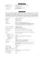
Depth
Width
Nominal
Hourly
Consumption
Test Point Pressure
Flue size
Splashback
Burner Ignition By
Floor Protection
Gas
510mm
405mm (NC-400), 805mm (NC-800), 1205mm (NC-1200)
NG:
LPG:
90MJ per Pan
85MJ per Pan
NG:
LPG:
1 KPa
2.75 KPa
From combustion chamber vertical riser into splashback outlet
420mm x50mm
250mm (H) x 90mm (W)
Hi Tension Spark Igniter incorporated within the thermostat. Pilot
light mounted adjacent to the left front duck bill burner with a fast cut
out thermocouple in conjunction with the flame failure control
Is by means of a 1.2 mm aluminized heat shield mounted off the base
of the angle iron frame. 100mm x 400mm x 460mm front to back (H
x W x D). Located against flue end of appliance.
INSTALLATION INSTRUCTIONS
(By Authotised Personnel Only)
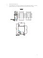
Gas point entry is 276mm above floor and located at the left side of the unit. A 20mm 3/4" BSP regulator is supplied
with each pan.
The installer is to supply and fit an isolating gas cock to the appliance for ease of servicing the control system. N.B.
Double and Triple units have separate inlet to each control and must have a separate gas cock.
The installer must install the appliance to AG601, 1995 Sections 5-12-4.5 and in accordance with local gas and water
regulations. Clearances form combustible walls sides – left and right 50mm. Rear wall 50mm and must be installed on
a fire proof base. Unit may be installed against fire proof walls. Refer installer instructions for special instructions for
this type of installation.
ADDENDA
“The installer must install the appliance to AG601, 1995 Section 5.12.4 and in accordance to local regulations,
attention must be give to Section 5.12.4.4 and 5.12.4.5.
5.12.4.6 Commercial catering equipment on combustible surface, where equipment is installed on a combustible
surface it shall be protected by fire resistant material.
Fire resistant material specifications where appliances are to be installed in non combustible area, the installer must
refer to AG601 and ensure the following side walls and bare walls have materials to the specifications referring to
standards A-S 1530.1 to be deemed not combustible and A-S 1530.3 have a zero (0) index for all of the following:
1.
2.
3.
4.
Ignitability
Spread of flame
Heat evolved
Smoke developed
N.B.
The thermal resistance not less than 0.05 M20 c/w but in no instance shall the material be of a thickness less
than 6mm.”
All models have a 20mm 3/4" BSP socket gas point or compression inlet.
The appliance must be installed as set out in the specifications i.e. Natural gas operating test point pressure 1 KPa.
Before leaving installation, check all gas and water fittings for leaks, and instruct operator in lighting and use of
appliance. N.B. This appliance must always be mounted on 320mm legs as supplied.
If unit fails to operate, please contact local distributor or call manufacturer on Phone: (613) 9543 9577
9544 1487.
Fax: (613)
3