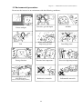
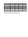
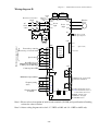
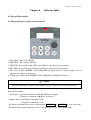
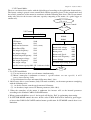
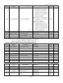
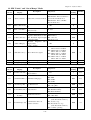
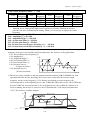
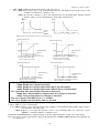
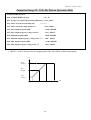
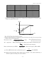
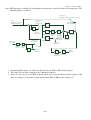
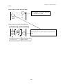
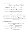
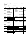
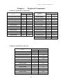
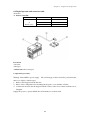
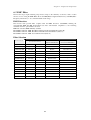
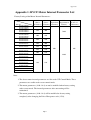
1
CARLO GAVAZZI
Automation
Components
VariFlex2
RVCF series
Advanced User Manual
230V
Class 1ph or 3ph
480V
Class 3ph
0.4~30.0kW
0.5~40HP
0.75~55kW
1.0~75HP
General Information
The manufacturer accepts no liability for any consequences resulting from
inappropriate, negligent or incorrect installation or adjustment of the optional
parameters of the equipment or from mismatching the variable speed drive with the
motor.
The contents of this guide are believed to be correct at the time of printing. In the
interests of commitment to a policy of continuous development and improvement, the
manufacturer reserves the right to change the specification of the product or its
performance, or the content of the guide without notice.
All rights reserved. No parts of this guide may be reproduced or transmitted in any form
or by any means, electrical or mechanical including, photocopying, recording or by an
information storage or retrieval system, without permission in writing from the
publisher.
Drive Software Version
This product is supplied with the latest version of user-interface and machine control
software. If this product is to be used in a new or existing system with other drives,
there may be some differences between their software and the software in this product.
These differences may cause the product to function differently. This may also apply to
drives returned from the Carlo Gavazzi Service Centre.
If there is any doubt, please contact your local Carlo Gavazzi representative or
Distributor.
Environmental Statement
The electronic variable speed drives have the potential to save energy and (through
increased machine/process efficiency) reduce raw material consumption and scrap
throughout their long working lifetime. In typical applications, these positive
environmental effects far outweigh the negative impacts of product manufacture and
end-of-life disposal.
Nevertheless, when the products eventually reach the end of their useful life, they can
very easily be dismantled into their major component parts for efficient recycling.
Many parts snap together and can be separated without the use of tools, while other
parts are secured with conventional screws.
Virtually all parts of the product are suitable for recycling.
Product packaging is of good quality and can be re-used. All the products come in
strong cardboard cartons which themselves have a high recycled fibre content. If not
re-used, these containers can be recycled. Polythene, used on the protective film and
bags from wrapping product, can be recycled in the same way. Carlo Gavazzi'
packaging strategy favours easily recyclable materials of low environmental impact,
and regular reviews identify opportunities for improvement.
When preparing to recycle or dispose of any product or packaging, please observe local
legislation and best practice.
© Copyright - Carlo Gavazzi – All rights reserved
Revision. R07
i
Advanced User Guide
This guide is to assist in installing and running the inverter to verify that the drive and
motor are working properly. Starting, stopping and speed control will be from the
keypad. If your application requires external control or special system programming,
consult the RVCF Instruction Manual supplied with your inverter.
Step 0 Products Inspection
Carlo Gavazzi’s inverters are all passed the function test before delivery. Please
check the followings when you received and unpacked the inverter:
The model and capacity of the inverter are the same as those specified in
your purchase order.
Check where there are any damages caused by transportation. Please do not
apply the power, and do contact Carlo Gavazzi’s sales representatives if any
of the above problems happened.
Step 1 Before Starting the Inverter
Please review Preface and Safety Precautions (page 0-1 through 1-3) of the RVCF
Instruction Manual. Verify drive was installed in accordance with the procedures as
described in RVCF Ambient Environment and Installation on pages 3-1 through 3-8.
If you feel this was abnormal, do not start the drive until qualified personnel have
corrected the situation. (Failure to do so could result in serious injury.)
Check inverter and motor nameplates to determine that they have the same
HP and voltage ratings. (Ensure that full load motor amps do not exceed
that of the inverter.)
Remove the terminal cover to expose the motor and power terminals.
a. Verify that AC power is wired to L1, L2, and L3 (pages 3-12).
b. Verify that Motor leads are connected to T1, T2, and T3 (pages 3-12).
(The two leads may need to be reversed if motor rotation is not correct).
ii
1. SEQ LED : 1_00 =1, LED Lit.
2. FRQ LED : 1_06 = 1/2/3/4, LED Lit
3. FWD LED: Forward Direction, LED action(Flash in stop, Keep Lit in operation).
4. REV LED : Reverse Direction, LED action(Flash in stop, Keep Lit in operation).
5. Four action of FUN, Hz/RPM, VOLT, AMP LED and display of four 7-segment
display, refer to operation description of the keypad.
6. LCD keypad without FUN, Hz/RPM, VOLT, AMP LED.
Step 2 Apply Power to the Drive
Apply AC power to the Drive and observe Operator. Four 7-segment Display
should read Power Voltage for 3~5 seconds and then read Frequency/Speed,
05.00. Four 7-segment Display and FWD LED should be flashed all the time.
Step 3 Check Motor Rotation Without Load
Press RUN key (FWD LED should light); Four 7-segment Display should run
from 00.00 to 05.00.
Check motor rotation. If it is not correct:
Press STOP key. Remove AC power. Wait for LED “charge” lamp to
extinguish.
Reverse motor leads T1 and T2. Restart the drive and check new rotation.
Press STOP key to stop the drive.
Step 4 Check Full Speed at 50Hz/60Hz
Frequency/Speed can be changed by pressing the up or down Arrow keys. To
move right or left for next digit, press SHIFT / RESET key. Press the READ /
ENTER key to set the speed.
Set frequency up to 50Hz/60Hz in accordance with the last rule.
Press RUN key. Check drive acceleration to full speed.
Press STOP key to stop drive and check deceleration.
Step 5 Other Operations
For information, see RVCF Instruction Manual.
Please refer to the following pages:
Set Accel .........................................................................................
Set Decel .........................................................................................
Set Max Speed ................................................................................
Set Min Speed .................................................................................
Set Motor Rated Current ................................................................
Set Control Mode (Vector, V/F) ......................................................
iii
p. 4-11
p. 4-11
p. 4-11
p. 4-11
p. 4-9
p. 4-7
Table of Content
Advanced User Guide
Chapter 0
Preface
0.1
Preface
0.2
Products Inspection
Chapter 1
Safety Precautions
1.1
Operation Precaution
1.1.1 Before Power ON
1.1.2 During Power ON
1.1.3 Before Operation
1.1.4 During Operation
1.1.5 During Maintenance
Chapter 2
Model Description
Chapter 3
Ambient Environment and Installation
3.1
Environment
3.2
Environmental Precautions
3.3
Inflammable Materials
3.3.1 Notice for Wiring
3.3.2 Applicable Specification of Magnetic Contactor and Wires
3.3.3 Precautions for Peripheral Applications
3.4
Specifications
3.4.1 Products Individual Specifications
3.4.2 General Specifications
3.5
Wiring Diagram RVCF Series Inverter
3.6
Description of Terminals Troubleshooting Inverter
3.7
Outline Dimensions
Chapter 4
Software Index
4.1
Keypad Description
4.1.1 Keypad Display and Operation Instruction
4.1.2 Operation Instruction of the Keypad
4.1.3 Operation Instruction of the LED Keypad
4.1.4 Operation Instruction of the LCD Keypad
4.1.5 Keypad Operating Example
4.2
Control Mode Selection
4.3
RVCF Programmable Functions List
4.4
Parameter Function Description
4.5
Specification Description on Built-in PLC Function
4.5.1 Basic Instruction
4.5.2 Function of Basic Instruction
4.5.3 Application Instructions
Chapter 5
Troubleshooting and Maintenance
5.1
Error Display and Remedy
5.1.1 Error which can not be Recovered Manually
5.1.2 Error which can be recovered manually and automatically
5.1.3 Error which can be recovered manually but not automatically
5.1.4 Special Conditions
5.1.5 Operation Errors
5.2
General troubleshooting
5.3
Quick troubleshooting RVCF
5.4
Routine Inspection and Period Inspection
iii
ii
0-1
0-1
0-1
1-1
1-1
1-1
1-2
1-2
1-2
1-3
2-1
3-1
3-1
3-2
3-3
3-3
3-5
3-6
3-10
3-10
3-13
3-15
3-17
3-19
4-1
4-1
4-1
4-2
4-3
4-4
4-5
4-6
4-8
4-20
4-57
4-57
4-58
4-59
5-1
5-1
5-1
5-2
5-3
5-4
5-5
5-6
5-7
5-13
5.5
Chapter 6
6.1
6.2
6.3
6.4
6.5
6.6
Appendix 1
Appendix 2
Appendix 3
Appendix 4
Appendix 5
Maintenance and Inspection
Peripheral Components
Reactor Specification at Input Side
Reactor Specification at DC Side
Braking Resistor
Digital Operator and Extension Cable
EMC Filter
Interface Card
6.6.1 RS-485 Interface Card
6.6.2 RS-232 Interface Card
6.6.3 Program Copy Unit
6.6.4 Keypad Installation Dimension
RVCF Motor Internal Parameter List
RVCF Parameters Setting List
RVCF Communication Time-out Table
CE certificate
Approvals Table: UL Listing and CE certification Information
iv
5-14
6-1
6-1
6-1
6-2
6-3
6-5
6-8
6-8
6-9
6-10
6-11
App1
App2
App3
App4
App5
Chapter 0 - Preface
Chapter 0 - Preface
0.1 Preface
To extend the performance of the product and ensure your safety, please read this manual
thoroughly before using the inverter. Should there be any problem in using the product
and can not be solved with the information provided in the manual, contact your nearest
Carlo Gavazzi’s distributor or our sales representatives who will be willing to help you.
Please keep using Carlo Gavazzi’s products in the future.
※ Precautions
The inverter is an electrical electronic product. For your safety, there are symbols such as
“Danger”, “Caution” in this manual to remind you to pay attention to safety instructions
on handling, installing, operating, and checking the inverter. Be sure to follow the
instructions for highest safety.
Danger
Indicates a potential hazard could cause death or serious personal injury
if misused.
Caution
Indicates that the inverter or the mechanical system might be damaged
if misused.
Danger
Do not touch any circuit boards or components if the charging indicator is still lit after
turned the power off.
Do not wire when the inverter is electrified. Do not check parts and signals on circuit
boards during the inverter operation.
Do not disassemble the inverter and modify internal wires, circuits and parts.
Ground the ground terminal of the inverter properly. As for 230V class ground to 100 Ω
or below, 480V class ground to 10Ω or below.
Caution
Do not perform a voltage test on parts inside the inverter. High voltage will easily destroy
these semiconductor parts.
Do not connect T1 (U), T2 (V), and T3 (W) terminals of the inverter to AC power supply.
CMOS ICs on the inverter’s main board are susceptible to static electricity. Do not touch
the main circuit board.
0.2 Products Inspection
Carlo Gavazzi’s inverters are all passed the function test before delivery. Please check the
followings when you received and unpacked the inverter:
The model and capacity of the inverter are the same as those specified in your
purchase order.
Check where there are any damages caused by transportation. Please do not apply the
power, and do contact Carlo Gavazzi’s sales representatives if any of the above
problems happened.
0-1
Chapter 1 - Safety Precautions
Chapter 1 - Safety Precautions
1.1
Operation Precaution
1.1.1 Before Power ON
Caution
The line voltage applied must comply with the inverter’s specified input voltage.
Danger
Make sure the main circuit connections are correct. L1(L), L2 and L3(N) are power-input
terminals and must not be mistaken for T1, T2 and T3. Otherwise, the inverter might be
damaged.
Caution
To avoid the front cover from disengaging, do not pull the cover during handling for
the heat sink should be fallen off. Accident falling down will damage the inverter or
injure to person, which should be avoided.
To avoid the risk of fire, do not install the inverter on a flammable object. Install it on
nonflammable object such as metal.
If several inverters are placed in the same control panel, add extra heat sink to keep
the temperature below 40°C to avoid overheat or fire.
When removing or installing the operator, turn OFF the power first, and manipulate
the operator following the instruction of the diagram to avoid operator error or no
display caused by bad contact.
Warning
This is a product of the restricted sales distribution class according to IEC 61800-3. In a
domestic environment this product may cause radio interference in which case the user
may be required to take adequate measures.
Caution
To ensure the safety of peripheral devices, it is strongly command to install a fast acting
fuse in the input side especially for higher output system. Regarding the specification of
fast acting fuse, please refer to P3-4.
1-1
Chapter 1 - Safety Precautions
1.1.2 During Power ON
Danger
Do not plug or unplug the connectors on the inverter when electrified to avoid the
control panel damage resulting from erratic transition voltage surge due to contact
bounce.
When momentary power loss is longer than 2 seconds (the larger of horse power, the
longer of time), the inverter does not have enough storage power to control the circuit;
Therefore, when power is regenerated, the operation of the inverter is based on the
setup of 1-00 / 2-05 and the condition of external switch, this is considered to be
「restart」in the following paragraphs.
When the momentary power loss is short, the inverter still has enough storage power
to control the circuit. Therefore, when power is regenerated, the inverter will
automatically restart depending on the setup of 2-00/2-01.
When restart the inverter, the operation of the inverter is based on the setup of 1-00
and 2-05 and the condition of external switch (FWD/REV button). Attention: the
start operation is irrelevant with 2-00/2-01/2-02/2-03.
1. When 1-00=0000, the inverter will not automatically run after restart.
2. When 1-00=0001 and the external switch (FWD/REV button) is OFF, the inverter
will not run after restart.
3. When 1-00=0001, the external switch (FWD/REV button) is ON, and 2-05=0000,
the inverter will run automatically after restart. Attention: In the sake of safety,
please turn off the external switch (FWD/REV button) after power loss to avoid
underling damage to the machine and the human body after sudden regeneration of
power.
To ensure the safety of people and machine, please refer to the description and
suggestion of 2-05
1.1.3 Before Operation
Danger
Make sure the model and capacity are the same as those set by 15-0.
Caution
The inverter will flash the power voltage set by 0-07 for 5 seconds when applying power.
1.1.4 During Operation
Danger
Do not engage or disengage the motor during operation. Otherwise, the over-current will
cause the inverter to disconnect or the main circuit to burn.
1-2
Chapter 1 - Safety Precautions
Danger
To avoid electric shock, do not take the front cover off during electrifying.
The motor will restart automatically after stop when auto-restart function is on. In this
case, do not get close to the machine.
Note: The stop switch is different from the usage of the emergency stop switch. It must
be set first to be effective.
Caution
Do not touch heat-generating components such as heat sink and braking resistor.
The inverter can drive the motor running from low speed to high speed. Verify the
allowable capacities range of the motor and the mechanism.
Note the settings related to the braking reactor.
Do not check signals on circuit boards while the inverter is running.
Caution
It is after 5 minutes that disassembling or checking the components could be performed as
power supply OFF and the indicator turned off.
1.1.5 During Maintenance
Caution
The inverter should be used in a non-condensed environment with temperature from –10°C
to +40°C and relative humidity of 95% non-condense.
Caution
When the inverter top cover has removed, it can be used in a non-condensed environment
with temperature from –10°C to +50°C and relative humidity of 95%, but the environment
should be free from water and metal dust.
1-3
Chapter 2 - Model description
Chapter 2 Model description
2.1 Label description
Inverter model
Input power
Output power
2.2 Ordering Key
2-1
Chapter 2 - Model description
2.3 Type Selection
Series
Frame Size
AC Supply
Phase
Drive
Voltage
Rating
Drive kW Rating
Option
RVCF A: Size1
1: 1-Phase
20: 230VAC
0040: 0.40kW, 0.50 HP Nil: Without Options
B: Size2
3: 3-Phase
40: 480VAC
0075: 0.75kW, 1.0 HP
C: Size3
0150: 1.5kW, 2.0 HP
D: Size4
0220: 2.2kW, 3.0 HP
E: Size5
0370: 3.70kW, 5HP
F: Size6
0550: 5.50kW, 7.5HP
0750: 7.50kW, 10HP
1100: 11.0kW, 15HP
1500: 15.0kW, 20HP
1850: 18.5kW, 25HP
2200: 22.0kW, 30HP
3000: 30.0kW, 40HP
3700: 37.0kW, 50HP
4500: 45.0kW, 60HP
5500: 55.0kW, 75HP
2-2
F: Built-in filter
Chapter 2 - Model description
2.4 Selection Guide
2-3
Chapter 3 - Ambient Environment and Installation
Chapter 3 Ambient Environment and Installation
3.1 Environment
The environment will directly affect the proper operation and the life span of the inverter, so install the
inverter in an environment complying with the following conditions:
Ambient temperature: -10oC ~ +40oC; without cover: -10oC ~ +50oC
Avoid exposure to rain or moisture.
Avoid direct sunlight.
Avoid oil mist and salinity.
Avoid erosive liquid and gas.
Keep away from radioactive and
Avoid dust, bats, and small metal pieces.
flammable materials.
Avoid electromagnetic interference (soldering machine, power machine).
Avoid vibration (punching machine). Add a vibration-proof pad if the situation cannot be
avoided.
If several inverters are placed in the same control panel, add extra heat sinks to keep the
temperature below 40oC.
Air exchanging fan
Inside the power
distributor
(Correct configuration)
Inside the
power
distributor
(Incorrect configuration)
Air exchanging fan
Inside the
power
distributor
(Correct configuration)
(Incorrect configuration)
Place the front side of the inverter onward and top upward to in favor of heat sink.
Install the inverter according to the following figures: (take the dustproof cover off in
favor of heat sinking if it is installed in a box or the environment allows to do so)
Air convection
-10oC - +40oC
(a) Front view
3-1
(b) Side view
Chapter 3 - Ambient Environment and Installation
3.2 Environmental precautions
Do not use the inverter in an environment with the following conditions:
Oil
Corrosive gas and liquid
Direct sunlight
Oil Mist
Salt
Salt
Wind, rain, and water
drops may get into
Strong vibration
Extreme low temperature
Excessive high temperature
Electromagnetic wave and
ultra high wave
Radioactive materials
Inflammable materials
(Near an electric welding machine)
3-2
Iron filings, dust
Chapter 3 - Ambient Environment and Installation
3.3 Inflammable materials
3.3.1 Notice for wiring
A. Screwdriver torque:
Wiring with a screwdriver or other tools and follow the torque listed below:
Horsepower
Power source
0.5/1/2(3φ)
200-240V
1/ 2
380-480V
2(1
φ)/3/5/7.5/10
3/ 5/ 7.5/ 10/15
15/20/25
20/25/30
30/40
40/50/60/75
Securing torque
Nominal torque for TM1 terminal
200-240V
380-480V
200-240V
380-480V
200-240V
380-480V
0.59/0.08
(LBS-FT / KG-M)
7.10/8.20
(LBS-IN/KG-CM)
1.5/0.21
(LBS-FT/KG-M)
18.00/20.28
(LBS-IN/KG-CM)
1.84/0.3
(LBS-FT / KG-M)
22.1/30
(LBS-IN/KG-CM)
4.42/0.66
(LBS-FT/KG-M)
53.1/66
(LBS-IN/KG-CM)
B. Power wires:
Power wires are connecting to L1, L2, L3, T1, T2, T3, P, BR and P1. Choose wires in
accordance with the following criteria:
(1) Use copper wires only. Deciding diameters of wires should be based on rating working at
105oC.
(2) For rating voltage of wires, the minimum voltage of 230VAC type is 300V, and 480VAC
type is 600V.
(3) For safety reason, the power wires should be fixed by type terminal.
C. Control wires:
Control wires are wires connecting to TM2 control terminal. Choose the wire in accordance with
the following criteria:
(1) Use copper wires only. Deciding diameters of wires should be based on rating working at
105oC.
(2) For rating voltage of wires, the minimum voltage of 230VAC type is 300V, and 480VAC
type is 600V.
(3) To avoid noise interference, do not route the control wires in the same conduit with power
wires and motor wires.
D. Nominal electrical specifications of the terminals Block:
The following list is nominal values of TM1:
Horsepower
Power source
0.5/1/ 2(3φ)
1/ 2
5/ 7.5/ 10
200-240V
2(1φ)/3/ 5/ 7.5/ 10/15
15/20/25
20/25/30
30
40/50
40
60/75
380-480V
Volts
Amps
15A
380-480V
200-240V
40A
600
200-240V
380-480V
200-240V
380-480V
200-240V
380-480V
80A
60A
100A
150A
Note: Nominal values of input and output signals (TM2) – follow the specifications of class 2
wiring.
3-3
Chapter 3 - Ambient Environment and Installation
E. Fuse types
Drive input fuses are provided to disconnect the drive from power in the event that a component fails in the
drive’s power circuitry. The drive’s electronic protection circuitry is designed to clear drive output short circuits
and ground faults without blowing the drive input fuses. Below table shows the RVCF input fuse ratings.
To protect the inverter most effectively, use fuses with current-limit function.
RK5, CC/T TYPE FUSE FOR RVCF
230V class(1φ)
1.2
100% CONT
Output AMPS (A)
3.1
Max.RK5
FUSE Rating(A)
10
Max.CC or T
FUSE Rating(A)
20
0.75
1.7
4.5
15
30
2
1.5
2.9
7.5
20
40
3
2.2
4.0
10.5
25
50
MODEL
HP
KW
KVA
RVCF A3200040
0.5
0.4
1.2
100% CONT
Output AMPS (A)
3.1
Max.RK5
FUSE Rating(A)
8
Max.CC or T
FUSE Rating(A)
10
RVCF A3200075
1
0.75
1.7
4.5
12
15
RVCF A3200150
2
1.5
2.9
7.5
15
20
RVCF B3200220
3
2.2
4.0
10.5
20
30
RVCF B3200370
5
3.7
6.7
17.5
30
50
RVCF C3200550
7.5
5.5
9.9
26
50
60
RVCF C3200750
10
7.5
13.3
35
60
70
RVCF D3201100
15
11.0
20.6
48
80
100
RVCF D3201500
20
15.0
27.4
64
100
125
RVCF D3201850
25
18.5
34.0
80
125
150
RVCF E3202200
30
22.0
41.0
96
160
200
RVCF E3203000
40
30.0
54.0
130
200
250
MODEL
HP
KW
KVA
RVCFA3400075
1
0.75
1.7
100% CONT
Output AMPS (A)
2.3
Max.RK5
FUSE Rating(A)
6
Max.CC or T
FUSE Rating(A)
10
RVCFA3400150
2
1.5
2.9
3.8
10
15
RVCF B3400220
3
2.2
4.0
5.2
10
20
RVCF B3400370
5
3.7
6.7
8.8
20
30
RVCF C3400550
7.5
5.5
9.9
13
25
35
RVCF C3400750
10
7.5
13.3
17.5
30
50
RVCF C3401100
15
11.0
20.6
25
50
60
RVCF D3401500
20
15.0
27.4
32
60
70
RVCF D3401850
25
18.5
34.0
40
70
80
RVCF D3402200
30
22.0
41.0
48
80
100
RVCF E3403000
40
30.0
54.0
64
100
125
RVCF E3403700
50
37.0
68.0
80
125
150
RVCF F3404500
60
45.0
82.0
96
150
200
RVCF F3405500
75
55.0
110.0
128
200
250
MODEL
HP
KW
KVA
RVCF A1200040
0.5
0.4
RVCF A1200075
1
RVCF B1200150
RVCF B1200220
230V class(3φ)
480V class(3φ)
*Fuse ratings are based upon 300V fuses for 230V inverter, and 500V for 480V inverters
3-4
Chapter 3 - Ambient Environment and Installation
Notice
To avoid shock hazards, do not touch any electrical component when the power is applied or
just after five minutes the power plug is unplugged. The other action should be performed
after the charge indicator went off.
Do not perform wiring on the inverter while it is still electrified. Disregard of this notice
could cause serious injure or death to persons.
This product is designed to use in Pollution Degree 2 environment or equivalent environments.
3.3.2 Applicable specification of magnetic contactor and wires
Molded-case circuit breaker/magnetic contactor
Carlo gavazzi bears no responsibility to service for failures caused by the following
conditions:
(1) A molded-case circuit breaker is not installed, or an improper or overrated breaker is
used, between the power source and the inverter.
(2) A magnetic contactor, a phase capacitor, or a burst absorber is connected between the
inverter and the motor.
RVCF Model
Molded-case circuit breaker
(Max Amp)
Main circuit terminals (TM1)
Signal terminals (TM2)
RVCFA1200040
RVCFA3200040
RVCFA1200075
RVCFA3200075
10A
20A
RVCFA1200150
RVCFB3200150
RVCFB1200220
RVCFB3200220
RVCFB3200370
30A
Wire gauge 2.0 mm2
Wire gauge 3.5 mm2
2
Wire gauge 0.75mm ( # 18 AWG)
RVCFC3200550 RVCFC3200750
RVCFD3201100
RVCFD3201500 RVCFD3201850
RVCF Model
Molded-case circuit breaker
50A
60A
100A
150A
(Max Amp)
Wire gauge 5.5 mm2
Wire gauge 14 mm2
Wire gauge 22 mm2
Main circuit terminals (TM1)
2
Signal terminals (TM2)
Wire gauge 0.75mm ( # 18 AWG)
RVCF Model
RVCFE3202200
RVCFE3203000
R V C F A3 4 0 0 0 7 5
R V C F A3 4 0 0 1 5 0
RVC FB3400220
RVC FB3400370
RVCFC3400550
RVCFC3400750
Molded-case circuit breaker
175A
175A
15A
20A
30A
(Max Amp)
Wire gauge 3.5mm2
Main circuit terminals (TM1) Wire gauge 38 mm2 Wire gauge 60 mm2 Wire gauge 2.0mm2
Signal terminals (TM2)
Wire gauge 0.75mm2 ( # 18 AWG)
RVCF Model
Molded-case circuit breaker
(Max Amp)
RVCFC3401100
RVCFD3401500
RVCFD3401850
RVCFD3402200
50A
50A
75A
100A
Main circuit terminals (TM1) Wire gauge 5.5mm2
Wire gauge 8mm2
Wire gauge 14mm2
Signal terminals (TM2)
Wire gauge 0.75mm2 ( # 18 AWG), terminal screw M3
3-5
Chapter 3 - Ambient Environment and Installation
RVCF Model
Molded-case circuit breaker
(Max Amp)
Main circuit terminals (TM1)
Signal terminals (TM2)
RVCFE3403000
RVCFE3403700
RVCFF3404500
RVCFF3405500
100A
125A
175A
175A
Wire gauge 22mm2
Wire gauge 38mm2 Wire gauge 60mm2
Wire gauge 0.75mm2 ( # 18 AWG), terminal screw M3
Use three-phase cage induction motor with capacity suitable for the inverter.
One inverter is driving several motors, the total current of all motors running simultaneously
must be less than the rated current of the inverter, and each motor has to be equipped with a
proper thermal relay.
Do not add capacitive component, such as a phase capacitor, LC or RC, between the inverter
and the motor.
3-6
Chapter 3 - Ambient Environment and Installation
3.3.3 Precautions for peripheral applications:
Power
Molded-case
circuit breaker
Magnetic
contactor
AC reactor
for power
improvement
Install fast
action fuse
Input noise
filter
RVCF inverter
Ground
Three-phase
cage motor
Power supply:
Make sure the voltage applied is correct to avoid
damaging the inverter.
A molded-case circuit breaker must be installed
between the AC source and the inverter.
Molded-case circuit breaker:
Use a molded-case circuit breaker that conforms to
the rated voltage and current of the inverter to
control the power ON/OFF and protect the inverter.
Do not use the inverter as the switch for run/stop
switch.
Leakage breaker:
Install a leakage breaker to prevent error operation
caused by electric leakage and to protect operators.
Setting current should be 200mA or above and the
operating time at 0.1 second or longer to prevent
malfunction.
Magnetic contactor:
Normal operations do not need a magnetic
contactor. But a contactor has to be installed in
primiary side when performing functions such as
external control and auto restart after power failure,
or when using brake controller.
Do not use the magnetic contactor as the run/stop
switch of the inverter.
AC reactor for power improvement:
When inverters below 230V/480V 15KW are
supplied with high capacity (above 600KVA) power
source or an AC reactor can be connected to
improve the power performance.
Install fast action fuse:
To ensure the safety of peripheral devices, please
install the fast action fuse. Regarding the
specification, please refer to P3-4.
Input noise filter:
A filter must be installed when there are inductive
load around the inverter.
Inverter:
Input power terminals L1, L2, and L3 can be used in
any sequence regardless of phases.
Output terminals T1, T2, and T3 are connected to U,
V, and W terminals of the motor. If the motor is
reversed while the inverter is forward, just swap any
two terminals of T1, T2, and T3.
To avoid damaging the inverter, do not connect the
input terminals T1, T2, and T3 to AC power.
Connect the ground terminal properly. 200 V series:
class 3 grounding, <100Ω; 480 V series : <10Ω.
Ground
3-7
Chapter 3 - Ambient Environment and Installation
Make external connections according to the following instruction. Check connections after
wiring to make sure all connections are correct. (Do not use the control circuit buzzer to check
connections).
The inverter uses dedicated power line
A general noise filter may not provide rightful results
RVCF
RVCF
Add a noise filter or separation transformer whenter
shares the power line with other machines.
the inverter shares the power line with other machines.
RVCF
RVCF
RVCF
(A) Main circuit’s wiring must separate from other high voltage or high current power line to
avoid noise interference. Refer to the figures below:
A noise filter in the output of the main circuit can suppress conductive noise. To
prevent radiative noise, the wires should be put in a metal pipe and distance from
signal lines of other control machines for more than 30 cm.
MCCB
Metal Box
Metal Pipe
Power Supply
Noise
Filter
7300CV
RVCF
Noise
Filter
above
Signal Wire
Controller
3-8
Chapter 3 - Ambient Environment and Installation
When the connection between the inverter and the motor is too long, consider the
voltage drop of the circuit. Phase-to-phase voltage drop (V) =
3 ×resistance of wire (Ω/km)×length of line (m)×current×10-3. And the number of
carriers must be adjusted based on the length of the line.
The length of the line between
the inverter and the motor
Number of carriers allowed
Below 25m
Below 100m
Over 100m
Below 16KHz Below 12KHz Below 8KHz
Below 5KHz
Settings of 3-22parameter
Below 50m
16
12
8
5
(B) The wiring of the control circuit must be separated and routed away from the main circuit
control line or other high voltage or current power lines to avoid noise interference
To avoid error actions caused by noise interference, shield the control circuit wiring
with a twisted wire, and connect the shielded wire to a ground terminal. Refer to the
figure below.
The wiring distance should not exceed 50 m.
Shielding Wire
To ground terminal
(refer to instructions of
filter wiring)
Protective
Do not connect this end
Wrapped with insulating
(C) Ground the ground terminal of the inverter properly. For 230V class ground 100Ω or less;
for 480V class ground 10Ω or less.
Ground wiring is based on the electrical equipment technical basis (AWG). The shorter,
the better.
Do not share the ground of the inverter to other high current loads (welding machine,
high power motor). Connect the terminals to ground respectively.
Do not make a loop when several inverters share a common ground point.
(a) Good
(b) Good
(c) Bad
(D) To ensure maximum safety, use proper wire gauges (AWG) for the main power circuit and
control circuit according to relative regulations.
3-9
Chapter 3 - Ambient Environment and Installation
(E) After wiring, check that the wiring is correct, wires are intact, and terminal screws are
secured.
3.4 Specifications
3.4.1 Products Individual Specifications
Single phase, 200-240V model
RVCF Model
RVCFA1200040
Horsepower(HP)
0 .5
1
2
3
Suitable Motor Capacity(KW)
0 .4
0 .7 5
1 .5
2 .2
Rated Output Current(A)
3 .1
4 .5
7 .5
1 0 .5
Rated Capacity(KVA)
1 .2
1 .7
2 .9
4 .0
RVCFA1200075
RVCF A1200075 RVCFB1200150 RVCFB1200220
Max. Input Voltage
Si n g le P ha se : 2 0 0 ~2 4 0 V +1 0 % - 1 5 % , 5 0 /6 0 H Z ± 5 %
Max. Output Voltage
T hr ee P ha se s : 0 ~2 4 0 V
Input Current(A)
8 .5
12
16
2 3 .9
Net Weight(Kg)
1 .2 ( 1 .3 )
1 .2 ( 1 .3 )
1 .5 ( 1 .8 )
1 .9 ( 2 .3 )
Allowable momentary power
loss time (second)
1 .0
1 .0
2 .0
2 .0
Three phases, 200 – 240V model
RVCF Model
Horsepower(HP)
Suitable Motor Capacity(KW)
Rated Output Current(A)
Rated Capacity(KVA)
Max. Input Voltage
Max. Output Voltage
Input Current(A)
Net Weight(Kg)
Allowable momentary power
loss time (second)
RVCF Model
Horsepower(HP)
Suitable Motor Capacity(KW)
Rated Output Current(A)
Rated Capacity(KVA)
Max. Input Voltage
Max. Output Voltage
Input Current(A)
Net Weight(Kg)
Allowable momentary power
loss time (second)
RVCFA3200040
RVCFA3200075
RVCFA3200150
RVCFB3200220
0 .5
1
2
3
0 .4
0 ,7 5
1 .5
2 .2
3 .1
4 .5
7 .5
1 0 .5
1 .2
1 .7
2 .9
4 .0
T hr ee Vo l ta ge : 2 0 0 ~2 4 0 V +1 0 % -1 5 % , 5 0 /6 0 H Z ± 5 %
T hr ee Vo l ta ge : 0 ~2 4 0 V
4 .5
6 .5
11
1 2 .5
1 .2
1 .2
1 .2
1 ,7 5
1 .0
1 .0
2 .0
2 .0
RVCFB3200370
RVCFC3200550
RVCFC3200750
RVCFD320110 0
5
7 .5
10
15
3 .7
5 .5
7 .5
11
1 7 .5
26
35
48
6 .7
9 .9
1 3 .3
2 0 .6
T hr ee Vo l ta ge : 2 0 0 ~2 4 0 V +1 0 % -1 5 % , 5 0 /6 0 H Z ± 5 %
Three Voltage: 0~240V
2 0 .5
33
42
57
1 .9
5 .6
5 .6
15
2 .0
2 .0
3-10
2 .0
2 .0
Chapter 3 - Ambient Environment and Installation
RVCF Model
Horsepower(HP)
Suitable Motor Capacity(KW)
Rated Output Current(A)
Rated Capacity(KVA)
Max. Input Voltage
Max. Output Voltage
Input Current(A)
Net Weight(Kg)
RVCFD3201500
RVCFD3201850
RVCFE3202200
RVCFE3203000
20
25
30
40
15
1 8 .5
22
30
64
80
96
130
2 7 .4
34
41
54
Three Voltage: 200~240V +10% -15%,50/60HZ ± 5%
Three Voltage: 0~240V
70
85
108
138
15
15
33
34
Allowable momentary power
loss time (second)
2 .0
2 .0
2 .0
2 .0
Three phases, 380 – 480V model
RVCF
RVCF Model
Horsepower(HP)
RVCFA3400075
1
RVCFA3400150
2
RVCFB3400220
3
RVCFB3400370
5
RVCFC3400550
7.5
Suitable Motor Capacity(KW)
0.75
1.5
2.2
3.7
5.5
Rated Output Current(A)
2.3
1.7
Rated Capacity(KVA)
Max. Input Voltage
Max. Output Voltage
Input Current(A)
Net Weight(Kg)
4.2
1.2
(1.3)
3.8
5.2
8.8
2.9
4,0
6.7
Three Voltage:380~480V +10% -15%, 50/60HZ ± 5%
Three Voltage: 0~480V
5.6
7.3
11.6
1.2
1.8
1.8
(1.3)
(2.2)
(2.2)
13,0
9.9
17,0
5.6
(6.6)
Allowable momentary power
loss time (second)
1.0
1.0
2.0
2.0
2.0
RVCF Model
Horsepower(HP)
RVCFC3400750
RVCFC3400750
10
RVCFC3401100
15
RVCFD3401500
20
RVCFD3401850
25
RVCFD3402200
30
Suitable Motor Capacity(KW)
7.5
11
15
18.5
22
Rated Output Current(A)
17.5
13.3
Rated Capacity(KVA)
Max. Input Voltage
Max. Output Voltage
Input Current(A)
Net Weight(Kg)
Allowable momentary power
loss time (second)
23
5.6
(6.6)
25
32
40
19.1
27.4
34
Three Voltage:380~480V +10% -15%, 50/60HZ ± 5%
Three Voltage: 0~480V
31
38
48
5.6
15
15
(6.6)
2.0
2.0
3-11
2.0
2.0
48
41
56
15
2.0
Chapter 3 - Ambient Environment and Installation
RVCF Model
Horsepower(HP)
RVCFE3403000
40
RVCFE3403700
50
RVCFF3404500
RVCFF3404500
60
RVCFF3405500
75
Suitable Motor Capacity(KW)
30
37
45
55
Rated Output Current(A)
64
54
Input Current(A)
80
96
68
82
Three Voltage:380~480V +10% -15%, 50/60HZ ± 5%
Three Voltage: 0~480V
75
92
112
142
Net Weight(Kg)
33
33
50
50
Allowable momentary power
loss time (second)
2.0
2.0
2.0
2.0
Rated Capacity(KVA)
Max. Input Voltage
Max. Output Voltage
NOTE1: DC Reactor is built-in for 30hp above in 230V class series.
NOTE2: DC Reactor is built-in for 40hp above in 480V class series.
3-12
128
110
Chapter 3 - Ambient Environment and Installation
3.4.2 General Specifications
Item
Control Mode
Range
Frequency Control
V/F or Current Vector Control
0.1~650.0 Hz
Start control torque
150%/1Hz (Current Vector)
Speed control range
1:50 (Current Vector)
Speed Control Precision
Setting resolution
Keypad setting
Display Function
External signal setting
Frequency Limit Function
Carrier frequency
V/F pattern
Acc/Dec control
General Control
RVCF TYPE
Multifunctional analog
output
±0.5% (Current Vector)
Digital: 0.01Hz( Note *1 ): Analog: 0.06Hz/ 60Hz(10bits)
Set directly with▲▼ keys or the VR on the keypad
Four digital LED (or 2×16 LCD) and status indicator; display
frequency/ speed/ line speed/ DC voltage/ Output voltage/ Current/
Rotation direction/ Inverter parameter/ Trouble Log/ Program
Version
1. External variable resistor/ 0-10V/ 0-20mA/ 10-0V/ 20-0mA
2. Performs up/down controls, speed control or automatic procedure
control with multifunctional contacts on the terminal block
(TM2)
Respectively setting upper/lower frequency limits and three-stage
prohibited frequencies
2 ~ 16 kHz
18-fixed patterns, 1 programmable pattern
Two-stage Acc/Dec time (0.1 – 3,600 seconds) and two-stage S
curves (refer to descriptions on 3-05)
6 functions (refer to description on 8-00/8-01)
Multifunctional input
30 functions (refer to description on 5-00~5-06)
Multifunctional output
16 functions (refer to description on 8-02~8-03)
Digital Input Signal
Other Function
NPN (SINK) / PNP (SOURCE) toggle
Momentary Power Loss Restart, Speed Search, Overload Detection, 8
preset speeds ( PLC use 16 preset speeds). Acc/Dec Switch (2
Stages), S Curves, 3-wire Control, PID control, torque boost, Slip
Compensation, Frequency Upper/ Lower Limit, Auto energy saving,
Modbus slave and PC/PDA Link, Auto Restart, Built-in Simple PLC
Function.
3-13
Chapter 3 - Ambient Environment and Installation
Item
Communication Control
Braking Torque
Operation temperature
Storage temperature
Humidity
Height
Vibration Sustention
1. Control by RS232 or RS485
2. One to one or One to more (RS485 ONLY) control.
3. BAUD RATE/STOP BIT/PARITY/bit can be set
﹪
About 20 , the model built-in braking transistor and connected
braking resistor is 100%
℃(note 2)
-20 ~ 60℃
-10 ~ 50
0 – 95% Relative Humidity(Non-condense)
Below 1000M
1G (9.8m/s2 )
EMC
Comply with requirement EN 61800-3 (with optional Filter).
LVD
Comply with requirement EN 50178
Enclosure
IP00 or IP20 ( NEMA 1 by external box attached)
Safety Level
UL 508C
Overload protection
The relays to protect the motor (the curve can be set) and the inverter
(150 % / 1min)
FUSE protection
The motor stops after FUSE melt
Under Voltage
:DC Voltage>410V 400V class:DC Voltage>820V
200V class:DC Voltage<190V 400V class:DC Voltage<380V
Momentary Power
Loss Restart
Stop for more than 15ms-power-loss can be restarted with spin start
after momentary power loss in Max 2 sec.
Over Voltage
Protective Functions
RVCF TYPE
Stall Prevention
200V class
Stall prevention for Acceleration/ Deceleration/ Operation.
Short-circuit output
terminal
Electronic Circuit Protection
Grounding Fault
Electronic Circuit Protection
Other Function
Protection for overheating of heat sink, over torque detection, error
contact control, reverse restriction, restrictions for direct start after
power up and error recovery, parameter lock up.
Note 1: The setting resolution of above 100Hz is 0.1Hz when controlled with operation keypad,
and 0.01 Hz when controlled using computer PC or programmable controller (PLC).
Note 2: –10 ~ 50℃ in distributor (without dustproof cover)
–10 ~ 40℃ outside distributor (with dustproof cover)
Note 3: 230V 15HP and above capacity are not CE complied
3-14
Chapter 3 - Ambient Environment and Installation
3.5 Wiring diagram RVCF series inverter
Wiring diagram I:
DC
reactor
Molded -case circuit breaker Magnetic Install fast
MCCB
contactor action fuse
(
MC
AC
Power
source
P
(Note2)
L1(R)
(
L2(S)
(
Braking
Resistor(note1)
BR
(Note2)
T1(U)
P1
(Note2)
Power
input
Induction
motor
Power T2(V)
output
T3(W)
L3(T)
200V:Class 3 ground
400V: Special ground
PE
ON-OFF
MC
Burst absorber
CON 2
RS485
Multifunction input terminal
TM2
Forward/stop or run/stop
S1
Reverse/stop or reverse /forward
S2
RS232
Digital
Control
panel
Memory Card
CON1
S3
Speed control
(Option Card)
S4
S5
Common point for PNP input
24V
R1A
PE
R1B
Common point for NPN
Reset /Error recovery
(Multifunction input terminal)
COM
R1C
S6/AI2
Multifunctional output terminals
250VAC/1A (30VDC/1A)
+ 10V
Frequency indicator
device
P
P
+
R2A
AIN
- COM
R2B
FM+
V
FM
Frequency indicator 0~10VDC
COM
SW2
NPN
SW3
I
SW1
PNP
SW2: AIN 0~10V/0~20mA selective
SW3: S6/AI2 0~10V/0~20mA selective
or 2~10V/4~20mA (after Ver.2.3)
I POSITION : 0~20mA signal
V POSITION : 0~10V signal
SW1: NPN/PNP selective
Note 1: Please refer to description of main circuit terminals (P1, BR) and specification of braking
resistor for value selection.
Note 2: Above wiring diagram refers for 0.4~1.5KW at 230V and 0.75~1.5KW at 480V only.
3-15
Chapter 3 - Ambient Environment and Installation
Wiring diagram II:
DC
reactor
Install
Magnetic fast
P
contactor action (Note
2)
(MC) fuse
L1(R)
Molded-case circuit breaker
MCCB
(
(
L2(S)
(
AC
Power
source
Braking
Resistor(Note1)
P1
(Note 2)
Power
input
BR
(Note 2)
T1(U)
Power T2(V)
output
T3(W)
L3(T)
ON-OFF
PE
200V: Class 3 ground
400V: Special ground
MC
CON 2
Burst
absorber
RS485
TM2
M ultifunction input terminal
Induction
motor
Forward/stop or run/stop
S1
Reverse/stop or reverse /forward
S2
RS232
Digital
control
panel
S3
Speed control
(Option Card)
Memory Card
JNSDOP
S4
CON1
S5
Reset/Error recovery
(Multifunction input terminal )
Common point for PNP input
Common point for NPN
S6
24V
TM2
24G
R1A
PE
R1B
R1C
Multifunction input terminal
AI2
Multifunctional output terminals
250VAC/1A (30VDC/1A)
+ 10V
Frequency setting
device
P
P
+
Frequency indicator FM
0~10VDC
R2A
AIN
- AGND
R2B
FM+
AGND
V
SW2
NPN
SW3
PE
I
SW1
PNP
SW2: AIN 0~10V/0~20mA selective
SW3: AI2 0~10V/0~20mA selective or
2~10V/4~20mA (after Ver2.3)
I POSITION : 0~20mA signal
V POSITION: 0~10V signal
SW1: NPN/PNP selective
Note 1: Please refer to description of main circuit terminals (P1, BR) and specification of braking
resistor for value selection.
Note 2: Above wiring diagram refers for 2.2~7.5KW at 230V and 2.2~11KW at 480V only.
3-16
Chapter 3 - Ambient Environment and Installation
3.6 Description of terminals of troubleshooting inverter
Descriptions of main circuit terminals
Symbol
R / L1 ( L )
S / L2
T / L3 ( N )
P1
BR
P1/ P
B1/P
B2
Ө
Description
Main power input
Braking resistor or connecting terminal: Used in cases where the inverter
frequently disconnects due to large load inertia or short deceleration time
(refer to specifications of braking resistor)
DC reactor connecting terminals
B 1 /P - Ө : D C p o wer s up p l y i np u t
B 1 /P -B 2 : E xt er na l b r a k i n g r es i sto r
Fo r 2 3 0 V : 1 5 ~2 0 HP a nd 4 8 0 V: 2 0 HP
-
⊕
U / T1
V / T2
W / T3
Single-phase: L/N
Three-phase: L1/L2/L3
-
⊕ - Ө : D C p o we r s up p l y inp u t o r E xte r nal
b r ak i n g u n it. Check Chapter 6.3
Fo r 2 3 0 V : 2 5 ~4 0 HP a nd 4 8 0 V: 2 5 ~7 5 HP
Inverter outputs
Descriptions of RVCF control circuit terminals
Symbol
Description
R2A
Multifunctional terminal – Normal open
R2B
Common contact
R1C
Normal close contact
Multifunctional output terminals
R1B
Normal
open
contact
R1A
Frequency knob (VR) power source terminal (pin 3)
10V
AIN
24V
COM
24G
AGND
FM+
For
230V:0.5~10HP,
480V:1~15HP
Contact rated capacity:
(250VAC/1A or 30VDC/1A)
Contact using description:(refer to 802, 8-03)
Analog frequency signal input terminal or multifunction input terminals S7 (H level:>8V, L level:<2V,
PNP only) (refer to5-06 description)
Common contact for S1~S5 (S6, S7) in PNP (Source) input. Shift to PNP position (refer to wiring
diagram) of SW1 when used PNP input
1. Common contact and analog input /output signal for S1~S5 in NPN (Sink) input.
Shift to NPN position (refer to wiring diagram I) of SW1 when used NPN input.
2. AGND for AIN,AI2 and FM+ (analog input /output signal) & 24G for S1~S6 (digital input /output
signal in NPN (Sink) input). Shift to NPN position (refer to wiring diagram II) of SW1 when used
NPN input.
The positive analog output for multifunction (refer to 8-00 description), the signal for output terminal is
0-10VDC (below 2mA).
3-17
Chapter 3 - Ambient Environment and Installation
Symbol
Function Description
S1
S2
S3
S4
S5
S6
Multifunction input terminals(refer to 5-00 ~ 5-04 description)
(S5 = Encoder input terminal, the Encoder voltage range: 19.2V~24.7V)
1. Multifunction input terminals ( Digital terminal H level:>8V, L level:<2V, PNP only) o r analog input
terminal AI 2 ( 0 ~1 0 Vd c/4 ~ 2 0 mA) ( refer to 5-05 description)
2 . T he V2 .9 ver s io n ( c o nt ai n s) ab o ve t h e ed i ti o n, S6 o nl y i s t h e Multi-function input
terminal u se, AI 2 h a ve r ep lac ed S6 to ta k e a n al o g i np ut u se . ( Above wiring diagram
refers for 2.2~7.5KW at 230V and 2.2~11KW at 480V only.)
Descriptions of SW function
SW2/SW3
Type of external signal
Remarks
V
0~10VDC analog signal
I
(1) External control is available as
1-06=0002
V
(2) Factory setting is voltage input
0~20mA analog signal
I
SW1
Type of external signal
Remarks
NPN (SINK) input
PNP (SOURCE) input
3-18
Factory default
Chapter 3 - Ambient Environment and Installation
3.7 Outline Dimensions
(1) Frame1 > Single phase RVCFA1200040, RVCFA1200075
Three phase RVCFA3200040, RVCFA3200075, RVCFA3200150,
RVCFA3400075, RVCFA3400150
(2) Frame2 > Single phase RVCFB1200150, RVCFB1200220
Three phase RVCFB3200220, RVCFB3200370, RVCFB3400220,
RVCFB3400370
(3) Frame3 > Three phase RVCFC3200550, RVCFC3200750
RVCFC3400550, RVCFC3400750, RVCFB3401100
3-19
Chapter 3 - Ambient Environment and Installation
C
(4) Frame4 > Three phase RVCFD3201100, RVCFD3201500, RVCFD3201850
RVCFD3401500, RVCFD3401850, RVCFD3402200
(5) Frame5 > Three phase RVCFE3202200, RVCFE3203000
RVCFE3403000, RVCFE3403700
(6) Frame6 > Three phase RVCFF3404500, RVCFE3405500
(Open Chassis Type-IP00)
3-20
Chapter 4 - Software Index
Chapter 4
Software Index
4.1 Keypad Description
4.1.1Keypad Display and Operation Instruction
1. SEQ LED: 1_00 =1/2/3, LED Lit.
2. FRQ LED: 1_06 = 1/2/3/4, LED Lit
3. FWD LED: Forward Direction, LED action (Flash in stop, Keep Lit in operation).
4. REV LED: Reverse Direction, LED action (Flash in stop, Keep Lit in operation).
5. Four action of FUN, Hz/RPM, VOLT, AMP LED and display of four 7-segment display, refer to
operation description of the keypad.
6. LCD keypad without FUN, Hz/RPM, VOLT, AMP LED and FREQ.SET knob.
Caution
To avoid impairing the keypad, do not operate it with screwdriver or sharp and hard tool.
Remote/Local Mode
․Local mode – Operation Command by RUN/STOP key on keypad
– Frequency Command by ▲▼ key on keypad
․Remote mode – Operating Command by 1-00
– Frequency Command by 1-06
To Change the Remote/Local mode, you must push FWD/REV and《/RESET key at the same time.
The Remote /Local mode of change can used in STOP mode, it can’t used in Run mode.
4-1
Chapter 4 - Software Index
4.1.2 Operation Instruction of the keypad
● :LED Light Lit
:LED Light Flash
Power On
Power Voltage (*1)
5 second later or Enter operation signal or Press DSP to modify frequency.
Frequency/Speed
HZ/RPM
^
/Line Speed
v <
HZ/RPM
Frequency/Speed/
Line Speed
(*3)
RUN/STOP
Frequency/Speed
HZ/RPM
/Line Speed
READ/
ENTER
(*2)
DSP
FUN
Selecting the
parameter group
^
FUN
READ/
ENTER
☉
v
FUN
Selecting the
parameter group
Parameter Setting
DSP
DSP
END
READ/
ENTER
DSP
Output Voltage
DSP
VOLT
DC Voltage
VOLT
DSP
Build-in PLC Status
DSP
Output Current
AMP
(*4)
*1: The inverter will flash the current setting of 0-07 (power supply voltage) after power up.
*2: 4-04, 4-05 determines the displaying of frequency, speed or line speed.
*3: It is not necessary to press ENTER key when stopped for modification. Refer to example 1, 2.
*4: Whether output current, output voltage, DC voltage, status of built-in PLC is displayed or not is
determined by 4-00 ~ 4-03 respectively.
4-2
Chapter 4 - Software Index
4.1.3 Operation Instruction of the LED keypad
Power On
● : LED Light Lit
: LED Light Flash
5 seconds later or Enter operation signal or Press DSP to modify the display frequency.
‧
HZ/RPM
^ v
<
HZ/RPM
‧
RUN/STOP
HZ/RPM
DSP
READ/
ENTER
‧
READ/
ENTER
FUN
☉
—
FUN
^ v
^ v
DSP
☉
—
FUN
FUN
READ/
ENTER
DSP
DSP
VOLT
VOLT
DSP
‧
DSP
4-3
AMP
Chapter 4 - Software Index
4.1.4 Operation Instruction of the LCD keypad
Power On
Power Source
220 V
5 second later or Enter operation signal or Press DSP to modify frequency
Master Freq.
60.00 Hz
^ v
<
Setting Freq.
060.00Hz
RUN/STOP
READ/
ENTER
Output Freq.
50.99 Hz
DSP
00- 00=Vector(CT)
READ/
ENTER
Control Mode
00-06=
Disabled
^ v
^ v
00- 06=Disabled
DSP
00-06=
Auto Tuning
1
Enabled
READ/
ENTER
END
DSP
0
DSP
Output Voltage
DSP
DC Bus Voltage
220V
DSP
311V
Output Current
3.1 Amp
Feedback
PLC State
0R
Stop
4-4
DSP
Chapter 4 - Software Index
4.1.5
Keypad Operating Example
Example 1. Modify frequency in stopping
FWD
FWD
<
Hz/RPM
Hz/RPM
FWD
FWD
1 second later
Hz/RPM
Hz/RPM
Example 2. Modify frequency in operating
FWD
FWD
Hz/RPM
Hz/RPM
Keep
Pressing FWD
FWD
Release the
button
Hz/RPM
Hz/RPM
Note : XX.XX shows the present output frequency. The value ranges from 59.58
to 0 Hz, depending on the length of time the key pressed.
Example 3. Modify frequency in running
FWD
FWD
Hz/RPM
Hz/RPM
FWD
FWD
Hz/RPM
Hz/RPM
After 2
seconds
FWD
Note : XX.XX shows the present output frequency.
Hz/RPM
4-5
Chapter 4 - Software Index
Example4. Modify the Value of Parameter
Example4. Modify the Frequency in Operating
DSP
READ
0.5 second later
ENTER
Example 5. Operation Control
6-00
Power On
6-00
FWD
REV
RUN
FWD
RUN
STOP
REV
STOP
FWD LED
●
REV LED
●
●: LED Lit
: LED Flash
: LED Go Out
4.2 Control Mode Selection
RVCF Series inverter has three control modes:
1. General Vector Control Mode
2. VT Vector Control Mode (Special for Blower, Pump).
4-6
Chapter 4 - Software Index
3. V/F Control Mode.
The user can choose these modes with the digital keypad according to the application characteristics.
The factory setting is general vector control mode. Before operation, please set the control mode and
the relative parameters of the motor in accordance with the following flow chart. (The Vector control
mode only suits for the inverter with same capacity comparing to the motor, or a grade bigger or
smaller one).
Setting procedure of
control mode
Vector Control
Control mode
V/F Control
Control mode selection
Control mode selection 0-00=2
0-00=0
Set the following parameter:
V/F Pattern
10-0
Torque Boost
10-1
Motor no load current
10-2 (<=0-02)
Motor Rated Slip
10-3
Max output frequency
10-4
Max output voltage
10-5
Medium output Frequency 10-6
Medium output voltage
10-7
Min output frequency
10-8
Min output voltage
10-9
Suitable motor capacity 0-02 (OL1 reference index)
0-00=1
Set the following parameter:
Motor rated voltage
0-01
Motor rated current
0-02
Motor power
0-03
Motor rated Speed
0-04
Motor rated Frequency 0-05
Power Voltage
0-07
Perform Auto tuning (0-06=1)
End
Note:
1. Use V/F Control Mode:
(1) Use one inverter to drive several motors simultaneously
(2) Motor’s nameplate is unknown or motor ’s specifications are too special, it will
cause Auto-tuning fault.
(3) Specification of inverter and motor differ more than 1 class.
2. One inverter drives several motors (Only V/F mode available), set the motor parameter complying
with the following rules:
(1). As for the current, sum the rated current of all motors.
(2). As for others, input correct VF Pattern parameter (10-4~10-9).
3. When the nameplate of the motor is unknown, the inverter will set the internal parameter
according to the standard CARLO GAVAZZI motor.
4. When parameter 0-00 does set to 2, the keypad will display ‘Err2’ in performing Auto tuning.
5. In VECTOR MODE control, the max. & min. value of 0-01~0-05 will be limited by grade upper
or lower than CARLO GAVAZZI standard motor specification. In VF MODE control, there is no
limitation.
4-7
Chapter 4 - Software Index
4.3 RVCF Programmable Functions List
Parameter
Group No.
Description
0-
Drive Operation Mode
1-
Start/Stop and Frequency Control Modes
2-
Manual/Automatic Restart Modes
3-
Operating Parameters
4-
Digital Display Operation Mode
5-
Multifunction Input Terminals (MFIT)
6-
Jog, and Preset (MFIT) Speed Setting on Keypad
7-
Analog Input Signal Operation
8-
Multifunction Output Relays and Output Signal Operation
9-
Drive and Load Protection Modes
10-
Volts/Hz Pattern Operation Mode
11-
PID Operation Mode
12-
PID "Limits" and "Out of Range" Mode
13-
Communication Mode
14-
Motor Auto-Tuning Parameters
15-
Drive Status and Function Reset
4-8
Chapter 4 - Software Index
0- Drive Operation Mode
Function
Code No.
LCD Display
Description
Range/Code
0-00
(Control Mode)
Control Mode
0-01
0-02
0-03
0-04
0-05
(Motor rated Volt)
(Motor rated Amps)
(Motor rated KW)
(Motor rated RPM)
(Motor rated Hz)
Motor Rated Voltage (Vac)
Motor Rated Current (Amp)
Motor Rated Power (kW)
Motor Rated Speed (RPM)
Motor Rated Frequency (Hz)
0-06
(Auto Tuning)
Motor Parameter Auto Tuning
0-07
(AC Input Volt)
AC Line Input Voltage (Vac)
0-08
(Select Language)
Language Selection
0000: Vector (General Purpose)
0001: Vector (Variable Torque)
0002: Volts/Hz (Refer to Parameter
Group 10- Volts/Hz Mode)
--------------------0000: Invalid
0001: Valid
230V SERIES:170.0~264.0
480V SERIES:323.0~528.0
0000: English
0001: German
0002: French
0003: Italian
0004: Spanish
Factory
Remarks
Setting
0000
*3
*3*5
*3*5
*3*5
*3*5*7
*3*5
0000
*3
0000
Only for
LCD
keypad
1- Start/Stop and Frequency Control Modes
Function
Code No.
1-00
1-01
LCD Display
(Run Source)
Description
Range/Code
Run Command Source Selection
Run/Stop-Forward/Reverse
(MFIT Run Mode) Operation Mode with External
Terminals
1-02
(Reverse Oper)
Prohibition of Reverse operation
1-03
(Keypad Stop)
Keypad Stop Button
1-04
(Starting Method)
1-05
(Stopping Method) Stopping Method Selection
Starting Method Selection
4-9
0000: Keypad
0001: External Run/Stop Control
(See 1-01)
0002: Communication
0003: Built-In PLC
0000: Forward/Stop-Reverse/Stop
0001: Run/Stop-Forward/Reverse
0002: 3-Wire Control ModeRun/Stop
0000: Enable Reverse Command
0001: Disable Reverse Command
0000: Stop Button Enabled
0001: Stop Button Disabled
0000: Normal Start
0001: Enable Speed Search
0000: Controlled Deceleration-toStop with DC Injection
Braking (Rapid Stop)
0001: Free run Stop
Factory
Setting
0000
0000
0000
0000
0000
Remarks
Function
Code No.
1-06
1-07
LCD Display
Description
Range/Code
Chapter 4 - Software Index
Factory
Remarks
Setting
0000: Keypad
0001: Potentiometer on Keypad
0002: External Analog Signal Input
or Remote Potentiometer
0003: Up/Down Frequency
Frequency Command Source
Control Using MFIT (S1 (Frequency Source)
Selection
S6)
0004: Communication setting
frequency
0005: Impulse (S5) setting
frequency (ver2.3)
0000: ‘Enter’ must be pressed after
frequency change with
Keypad Operation with Up/Down
Up/Down Keys on keypad.
(Keypad Up/Down)
Keys in Run Mode
0001: Frequency will be changed
directly when Up/Down
Keys are Pressed
0000
0000
2- Manual/Automatic Restart Modes
Function
Code No.
LCD
Display
2-00
(PwrL Selection)
2-01
(PwrL Ridethru T)
2-02
(Delay of Restart)
2-03
(Num of Restart)
2-04
2-05
2-06
2-07
2-08
Description
Range/Code
Momentary Power Loss and
Restart
Momentary Power Loss
Ride-Thru Time (Seconds)
Auto Restart Delay Time
(Seconds)
Number of Auto Restart
Attempts
0000: Momentary power loss and
restart disable
0001: Momentary power loss and
restart enable
0002: Momentary power loss and
restart enable while CPU is
operating. (According to the
capacity of DC power)
0.5
0.0 - 800.0
0.0
0 - 10
Auto Restart Method
4-10
0000
0.0 - 2.0
0000: Enable Speed Search
0001: Normal Start
0000: Enable Direct running after
power up
(Direct Start Sel) Direct Running After Power Up
0001: Disable Direct running after
power up
(Delay-on Timer) Delay-ON Timer (Seconds)
0.0-300.0
0000: Enable Reset Only when Run
Command is Off
(Reset Mode Sel) Reset Mode Setting
0001: Enable Reset when Run
Command is On or Off
Kinetic Energy Back-up
0.0:Disable
(KEB Decel Time)
Deceleration Time
0.1~25.0: KEB Deceleration Time
(Auto Restart)
Factory
Remarks
Setting
0
0000
0001*8
0.0
0000
0.0
Chapter 4 - Software Index
3- Operating Parameters
Function
Code No.
LCD
Display
Description
Range/Code
3-00
(Freq Upper Limit) Frequency Upper Limit (Hz)
0.01 - 650.00
3-01
3-02
3-03
(Freq Lower Limit) Frequency Lower Limit (Hz)
0.00 - 650.00
(Accel Time 1)
Acceleration Time # 1 (Seconds) 0.1 – 3600.0
(Decel Time 1)
Deceleration Time # 1 (Seconds) 0.1 – 3600.0
3-04
(S-Curve 1)
S-Curve Acc/Dec # 1 (Seconds) 0.0 - 4.0
3-05
(S-Curve 2)
S-Curve Acc/Dec # 2(Seconds)
3-06
(Accel Time 2)
3-07
(Decel Time 2)
3-08
(Jog Accel Time)
3-09
(Jog Decel Time)
3-10
(DCInj Start Freq)
3-11
(DCInj Level)
3-12
(DCInj Time)
3-13
3-14
(Skip Freq 1)
(Skip Freq 2)
Acceleration Time # 2 (MFIT)
(Seconds)
Deceleration Time # 2 (MFIT)
(Seconds)
Jog Acceleration Time (MFIT)
(Seconds)
Jog Deceleration Time (MFIT)
(Seconds)
DC Injection Brake Start
Frequency (Hz)
DC Injection Brake Level (%)
DC Injection Brake Time
(Seconds)
Skip Frequency # 1 (Hz)
Skip Frequency # 2 (Hz)
3-15
(Skip Freq 3)
3-16
(Skip Bandwidth)
3-17
3-18
3-19
(Parameter Lock)
0.1 – 3600.0
10.0
*1
0.1 – 3600.0
10.0
*1
0.1 - 25.5
0.5
*1
0.1 - 25.5
0.5
*1
0.1 - 10.0
1.5
0.0 – 20.0
5.0
0.0 - 25.5
0.5
0.00 - 650.00
0.00 - 650.00
0.0
0.0
*1
*1
Skip Frequency # 3 (Hz)
0.00 - 650.00
0.0
*1
Skip Frequency Bandwidth(±
Hz)
0.00 - 30.00
0.0
*1
Parameter Lock
Fan Control
3-20
(Energy Save Mode) Energy Saving Mode *1
3-21
3-22
(Energy Save Gain) Energy Saving Gain (%)*1
(Carrier Freq)
Carrier Frequency (kHz)
Center Frequency (CF) of
(Center F of Trav)
Traverse Run (%)
3-23
0000: Enable all Functions
0001: 6-00 - 6-08 cannot be changed
0002: All Functions Except 6-00 6-08 cannot be changed
0003: Disable All Function
0000: Disable
0001: Inverter to Copy Unit
0002: Copy Unit to Inverter
0003: Verify
0000: Auto (Depend on temp.)
0001: Operate while in RUN mode
0002: Always Run
0003: Always Stop
0000: Disabled
0001: Controlled by MFIT at Set
Frequency
0 - 100
2 - 16
(ROM Pack Operate) Copy Unit
(Fan Control)
0.0 - 4.0
Factory
Remarks
Setting
50.00/
*4
60.00
0.00
10.0
*1
10.0
*1
0.2
1.0 *9
0.2
1.0 *9
5.00 – 100.00
4-11
*7
0000
0000
0000
0000
*6
80
10
*6
20.00
Function
Code No.
LCD
Display
3-24
(Amplit. of Trav)
3-25
(Drop of Trav)
3-26
(Acc T of Trav)
3-27
(Dec T of Trav)
3-28
(Rise Deviated)
3-29
(Lower Deviated)
3-30
(Start Freq)
※
Description
Range/Code
Amplitude (A) of Traverse Run
(%)
Drop (D) of Traverse Run (%)
Acc Time (AT) of Traverse Run
(Seconds)
Dec Time (DT) of Traverse Run
(Seconds)
Rise (X) Deviated Traverse (%)
Lower (Y) Deviated Traverse
(%)
( )
Start frequency Hz
Chapter 4 - Software Index
Factory
Remarks
Setting
0.1 – 20.0
10.0
0.0 – 50.0
0.0
0.5 – 60.0
10.0
0.5 – 60.0
10.0
0.0 – 20.0
10.0
0.0 – 20.0
10.0
0.0-10.0
0.0
Notes: 1. Energy Saving Mode is available only under Volts/Hz Mode (0-00 = 0002).
4- Digital Display Operation Mode
Function
Code No.
LCD
Display
Description
Range/Code
4-00
(Motor Curr Disp) Motor Current Display Selection
4-01
(Motor Volt Disp)
4-02
(Bus Volt Disp)
4-03
(PLC Status Disp)
4-04
(Display Scaling)
Motor Voltage Display Selection
0000: Disable Motor Current Display
0001: Enable Motor Current Display
0000: Disable Motor Voltage Display
0001: Enable Motor Voltage Display
DC Bus Voltage Display
0000: Disable Bus Voltage Display
Selection
0001: Enable Bus Voltage Display
PLC Status Display Selection
Custom Units (Line Speed)
0000: Disable PLC Status Display
0001: Enable PLC Status Display
0 - 9999
Value
Factory
Remarks
Setting
0000
*1
0000
*1
0000
*1
0000
*1
1800
*1
0000
*1
0000
*1
0000: Drive Output Frequency is
Displayed
0001: Line Speed is Displayed in
Integer (xxxx)
4-05
(Display Units)
Custom Units (Line Speed)
0002: Line Speed is Displayed with
Display Mode
One Decimal Place (xxx.x)
0003: Line Speed is Displayed with
Two Decimal Places (xx.xx)
0004: Line Speed is Displayed with
Three Decimal Places (x.xxx)
4-06
(PID Fdbk Display) PID Feedback Display Selection
4-12
0000: Disable PID Feedback Display
0001: Enable PID Feedback Display
Chapter 4 - Software Index
5- Multifunction Input Terminals (MFIT)
Function
Code No.
LCD
Display
Description
Range/Code
5-00
(MFIT S1 Sel)
Multifunction Input Term. S1
5-01
(MFIT S2 Sel)
Multifunction Input Term. S2
5-02
(MFIT S3 Sel)
Multifunction Input Term. S3
5-03
(MFIT S4 Sel)
Multifunction Input Term. S4
5-04
(MFIT S5 Sel)
Multifunction Input Term. S5
5-05
(MFIT S6 Sel)
Multifunction Input Term. S6
5-06
(MFIT AIN Sel)
Multifunction Input Term. AIN
5-07
(MFIT Scan Time)
Multifunction Input Term. S1 S6 Signal Verification Scan
Time (mSec X 4 )
4-13
0000: Forward/Stop Command #1 (note)
0001: Reverse/Stop Command #2 (note)
0002: Preset Speed # 1 (6-02)
0003: Preset Speed # 2 (6-03)
0004: Preset Speed # 3 (6-05)
0005: Jog
0006: Acc/Dec # 2
0007: Emergency Stop A Contact
0008: Base Block
0009: Speed Search
0010: Energy Saving
0011: Control Signal Selection
0012: Communication Selection
0013: Acc/Dec Disabled
0014: Up Command
0015: Down Command
0016: Master/Auxiliary Speed
0017: PID Function Disabled
0018: Reset
0019: Encoder input terminal
( terminal S5 )
0020: PID feedback signal A12
( terminal AI2 )
0021: AI2 Bias signal 1 input
( terminal AI2 )
0022: AI2 Bias signal 2 input
( terminal AI2 )
0023: Analog input (terminal AIN)
0024: PLC Application
0025: Traverse Run
0026: Traverse run upper deviation
0027: traverse run lower deviation
0028: Power Source Detect for KEB
Function
0029: Emergency Stop B Contact *7
1 – 100
Factory
Remarks
Setting
0000
0001
0002
0003
0004
0018
0023
5
Function
Code No.
LCD
Display
Description
Range/Code
0000: When the MFITs are
Programmed for Up/Down
Frequency Control, the Set
Frequency will remain when
the Drive stops. And when the
Drive stops, Up/Down
Function Disabled.
0001: Up/Down is used. The preset
frequency is reset to 0 Hz as
the inverter stops.
0002: When the MFITs are
Programmed for Up/Down
Frequency Control, the Set
Frequency will remain when
the Drive stops. And when the
Drive stops, Up/Down
Function Enabled. *7
5-08
(Stop Sel by MFIT) Stop Mode Using MFIT
5-09
(Step Up/Down Fun) Step of Up/Down Function (Hz) 0.00 – 5.00
5-10
5-11
5-12
Chapter 4 - Software Index
Factory
Remarks
Setting
(Pulse Inp. Mult.)
Encoder Impulse Ratio
0.001 – 9.999
Select the source of auxiliary
(Ref.Source2)
0-4
frequency command
#3 (note)
(AI2 Function)
AI2 Function Set
20 / 21 / 22
Notes: #1. To switch to Run/Stop with Function 1-01 = 0001.
#2. To switch to Forward/Reverse with Function 1-01 = 0001.
#3. For 2.2~7.5KW at 230V and 2.2~11KW at 480V only.
0000
0.00
1.000
*7
0
*7
20
*11
6- Jog, and Preset (MFIT) Frequency Setting on Keypad
Function
Code No.
LCD
Display
6-00
(Keypad Freq)
6-01
(Jog Freq)
6-02
Description
Range/Code
Factory
Remarks
Setting
Keypad Frequency (Hz)
0.00 - 650.00
5.00
*1
Jog Frequency (Hz)
0.00 - 650.00
2.00
*1
(Preset Speed #1)
Preset Speed # 1 (Hz)
0.00 - 650.00
5.00
*1
6-03
(Preset Speed #2)
Preset Speed # 2 (Hz)
0.00 - 650.00
10.00
*1
6-04
(Preset Speed #3)
Preset Speed # 3 (Hz)
0.00 - 650.00
20.00
*1
6-05
(Preset Speed #4)
Preset Speed # 4 (Hz)
0.00 - 650.00
30.00
*1
6-06
(Preset Speed #5)
Preset Speed # 5 (Hz)
0.00 - 650.00
40.00
*1
6-07
(Preset Speed #6)
Preset Speed # 6 (Hz)
0.00 - 650.00
50.00
*1
6-08
(Preset Speed #7)
Preset Speed # 7 (Hz)
0.00 - 650.00
60.00
*1
7- Analog Input Signal Operation
Function
Code No.
7-00
7-01
LCD
Display
(AIN Gain)
(AIN Offset)
7-02
(AIN Bias)
AIN Bias Selection
7-03
(AIN Slope)
AIN Slope
Description
Range/Code
0 - 1000 *10
0 - 100
0000: Positive
0001: Negative
0000: Positive
0001: Negative
AIN Gain (%)
AIN Bias (%)
4-14
Factory
Remarks
Setting
100
*1
0
*1
0000
*1
0000
*1
Function
Code No.
LCD
Display
7-04
(AIN Scan Time)
7-05
(AI2 Gain)
Description
Range/Code
AIN Signal Verification Scan
Time (AIN, AI2)
(mSec x 2)
AI2 Gain (%)
Chapter 4 - Software Index
Factory
Remarks
Setting
1 - 100
50
0 - 200
100
*1
Notes: 7-00~7-04 is available when 5-06=0023 (AIN term.=Analog input)
8- Multifunction Output Relays and Output Signal Operation
Function
Code No.
LCD
Display
Description
Range/Code
Analog Output Voltage Mode
(0 - 10 VDC, Term. FM+)
8-00
(AO Mode Sel)
8-01
(AO Gain)
8-02
(Relay R1 Sel)
Output Relay R1 Operation
Mode
8-03
(Relay R2 Sel)
Output Relay R2 Operation
Mode
8-04
8-05
Analog Output Gain (%)
0000: Output Frequency
0001: Frequency Setting
0002: Output Voltage
0003: DC Voltage
0004: Output Current
0005: PID Feedback *7
0 - 200
0000: Run
0001: Frequency Reached
(Frequency Command) (Set
Frequency ± 8-05)
0002: Set Frequency (8-04 ± 8-05)
0003: Frequency Threshold Level (>
8-04) - Frequency Reached
0004: Frequency Threshold Level (<
8-04) - Frequency Reached
0005: Over torque Threshold Level
0006: Fault
0007: Auto Restart
0008: Momentary AC Power Loss
0009: Emergency Stop Mode
0010: Coast-to-Stop Mode
0011: Motor Overload Protection
0012: Drive Overload Protection
0013: PID Feedback Signal Loss
0014: PLC Operation
0015: Power On *7
Frequency Reached (Hz)
0.00 - 650.00
(Refer to 8-02: 0001)
Frequency Reached Bandwidth
(Freq Agree width)
0.00 - 30.00
(± Hz)
(Freq Agree)
Factory
Remarks
Setting
0000
*1
100
*1
0006
0000
0.00
*1
2.00
*1
9- Drive and Load Protection Modes
Function
Code No.
LCD
Display
9-00
(Trip ACC Sel)
9-01
(Trip ACC Level)
Description
Range/Code
Factory
Remarks
Setting
Trip Prevention Selection
During Acceleration
0000:Enable Trip Prevention During
Acceleration
0001: Disable Trip Prevention
During Acceleration
0000
Trip Prevention Level During
Acceleration (%)
50 - 300
200
150*9
4-15
Function
Code No.
LCD
Display
9-02
(Trip DEC Sel)
9-03
(Trip DEC Level)
9-04
(Trip RUN Sel)
Trip Prevention Selection in
Run Mode
9-05
(Trip Run Level)
Trip Prevention Level In Run
Mode (%)
9-06
(Dec Sel Trip RUN)
Trip Prevention Deceleration
Time Selection in Run Mode
9-07
(Dec Time Trip
RUN)
Deceleration Time In Trip
Prevention Mode (Seconds)
9-08
9-09
9-10
9-11
9-12
9-13
9-14
9-15
Description
Trip Prevention Selection
During Deceleration
Trip Prevention Level During
Deceleration (%)
Chapter 4 - Software Index
Factory
Range/Code
Remarks
Setting
0000: Enable Trip Prevention During
Deceleration
0000
0001: Disable Trip Prevention
During Deceleration
200
50 - 300
150*9
0000: Enable Trip Prevention in Run
Mode
0000
0001: Disable Trip Prevention in
Run Mode
200
50 - 300
150*9
0000: Trip Prevention Deceleration
Time Set by 3-03
0000
0001: Trip Prevention Deceleration
Time Set by 9-07
0.1 – 3600.0
0000: Enable Electronic Motor
Overload Protection
(Motor OL1 Sel)
0001: Disable Electronic Motor
Overload Protection
0000: Electronic Motor Overload
Protection Set for
Non-Inverter Duty Motor
(Motor type)
Motor type Selection
0001: Electronic Motor Overload
Protection Set for Inverter
Duty Motor
0000: Constant Torque (OL =103 %)
Motor Overload Protection
(150 % for 1 Minute)
(Motor OL1 Curve)
0001: Variable Torque (OL = 113 %)
Curve Selection
(123 % for 1 Minute)
0000: Coast-to-Stop After Overload
Protection is Activated
Operation After Overload
0001: Drive Will Not Trip when
(Motor OL1 Operat)
Protection is Activated
Overload Protection is
Activated (OL1)
0000: Disable Over torque Operation
0001: Enable Over torque Operation
Only if at Set Frequency
(Torq Det Sel)
Over torque Detection Selection
0002: Enable Over torque Operation
while the Drive is in Run
Mode
0000: Drive will Continue to
Operate After Over torque is
Operation After Over torque
Activated
(Torq Det Operat)
Detection is Activated
0001: Coast-to-Stop After Over
torque is Activated
Over torque Threshold Level.
(Torq Det Level)
30 - 200
(%)
Over torque Activation Delay
(Torq Det Delay)
0.0 - 25.0
Time (Seconds)
Electronic Motor Overload
Protection Operation Mode
4-16
3.0
0000
0000
0000
0000
0000
0000
160
0.1
Chapter 4 - Software Index
10- Volts/Hz Operation Mode
Function
Code No.
10-0
10-1
10-2
10-3
LCD
Display
(V/F Selection)
Description
Range/Code
Volts/Hz Patterns
Volts/Hz Curve Modification
(Torque Boost)
(Torque Boost) (%)
Motor No Load Current
(Motor noLoad Amp)
(Amps AC)
(Motor rated slip) Motor Slip Compensation (%)
10-4
(Max frequency)
10-5
(Max Voltage)
10-6
(Mid frequency)
10-7
(Mid Voltage)
10-8
(Min frequency)
10-9
(Min Voltage)
0 - 18
0 – 30.0
0.0
----0.0 – 100.0
Maximum Frequency (Hz)
0.20 - 650.00
Maximum Frequency Voltage
Ratio (%)
0.0 - 100.0
Mid Frequency (Hz)
Mid Frequency Voltage Ratio
(%)
Minimum Frequency (Hz)
Minimum Frequency Voltage
Ratio (%)
Factory
Remarks
Setting
0/9
*4*6
*1*6
*5*6
0.0
50.00/
60.00
*1*6
*4*6
100.0
*6
0.10 - 650.00
25.00/
30.00*7
*4*6
0.0 - 100.0
50.0*7
*6
0.50/ 0.60
*6
1.0*7
*6
0.10 - 650.00
0.0 - 100.0
11- PID Operation Mode
Function
Code No.
LCD
Display
11-0
(PID Mode Sel)
11-1
11-2
11-3
11-4
(Feedback Gain)
(PID Gain)
(PID I Time)
(PID D Time)
11-5
(PID Offset)
11-6
(PID Offset Adj)
11-7
(Output Filter T)
Description
Range/Code
0000: Disabled
0001: Bias D Control
0002: Feedback D Control
0003: Bias D Reversed
Characteristics Control
0004: Feedback D Reversed
Characteristics Control
0005: Frequency Command + Bias D
Mode Selection
Control
0006: Frequency Command +
Feedback D Control
0007: Frequency Command + Bias D
Reversed Characteristics
Control
0008: Frequency Command +
Feedback D Reversed
Characteristics Control
Feedback Gain
0.00 - 10.00
Proportional Gain
0.0 - 10.0
Integration Time (Seconds)
0.0 - 100.0
Differentiation Time (Seconds) 0.00 - 10.00
0000: Positive
PID Offset
0001: Negative
PID Offset Adjust (%)
0 - 109
Output Lag Filter Time
0.0 - 2.5
(Seconds)
4-17
Factory
Remarks
Setting
0000
1.00
1.0
10.0
0.00
*1
*1
*1
*1
0000
*1
0
*1
0.0
*1
Chapter 4 - Software Index
12- PID "Limits" and "Out of Range" Mode
Function
Code No.
12-0
12-1
12-2
12-3
12-4
12-5
12-6
12-7
12-8
LCD
Display
Description
Range/Code
0000: Disabled
0001: Enabled - Drive Continues to
(Fb Los Det Sel) Feedback Loss Detection Mode Operate After Feedback Loss
0002: Enabled - Drive "STOPS"
After Feedback Loss
Feedback Loss Detection Level
(Fb Los Det Level)
0 - 100
(%)
Feedback Loss Detection Delay
(Fb Los Det Time)
0.0 -25.5
Time (Seconds)
(PID I Limit)
Integration Limit Value (%)
0 - 109
Integration Value Resets to Zero 0000: Disabled
(I Time value Sel) when Feedback Signal Equals 0001: 1 Second
the Intended Value
0030: 30 Seconds
Allowable Integration Error
(I Error Margin) Margin (Units)
0 - 100
(1 Unit = 1/8192)
0000: AIN=0~10V or 0~20mA
AI2= 0~10V or 0~20mA
0001: AIN=0~10V or 0~20mA
AI2=2~10V or 4~20mA
(AIN AI2 Source) AIN or AI2 Source signal
0002: AIN=2~10V or 4~20mA
AI2=0~10V or 0~20mA
0003: AIN=2~10V or 4~20mA
AI2=2~10V or 4~20mA
(Sleep Level)
Sleep Function Operation Level 0.00-650.00
(Sleep Delay Time) Sleep Function Delay Time
0.0-25.5
Factory
Remarks
Setting
0000
0
1.0
100
*1
0000
0
0000
*7
0.0
0.0
13- Communication Mode
Function
Code No.
LCD
Display
13-0
(Serial Comm Adr)
Description
Assigned Communication
Station Number
13-1
(Serial Baud Rate) Baud Rate Setting (bps)
13-2
(Comm Stop Bit)
13-3
Range/Code
1 - 254
0000: 4800
0001: 9600
0002: 19200
0003: 38400
0000: 1 Stop Bit
0001: 2 Stop Bits
0000: Without Parity
0001: With Even Parity
0002: With Odd Parity
0000: 8-Bits Data
0001: 7-Bits Data
0000: Deceleration to stop.
(3-03: Deceleration time 1).
0001: Coast to stop.
0002: Deceleration to stop.
(3-07: Deceleration time 2).
0003: continue operating.
Stop Bit Selection
(Comm Parity Sel) Parity Selection
13-4
(Comm Data
Format)
13-5
(Comm Err Ope Sel)
Data Format Selection
Communication time-out
operation selection
4-18
Factory
Remarks
Setting
1
*2*3
0003
*2*3
0000
*2*3
0000
*2*3
0000
*2*3
0000
*11
Function
Code No.
LCD
Display
13-6
(Comm Err Det Tim)
Description
Range/Code
Communication time-out
detection time
00.0 ~ 25.5 Sec
Chapter 4 - Software Index
Factory
Remarks
Setting
00.00
*11
14- Motor Auto-Tune Parameters
Function
Code No.
14-0
14-1
14-2
LCD
Display
(Stator Resistor)
(Rotor Resistor)
(Equi Inductance)
14-3
(Magnet Current)
14-4
(Ferrite Loss)
Description
Range/Code
Stator Resistance (Ohms)
Rotor Resistance (Ohms)
Equivalent Inductance (mH)
Magnetizing Current (Amps
AC)
Ferrite Loss Conductance (gm)
-------------
Factory
Remarks
Setting
*5
*5
*5
-----
*5
-----
*5
15- Drive Status and Function Reset
Function
Code No.
15-0
15-1
15-2
15-3
15-4
15-5
15-6
LCD
Description
Display
(Drive Model)
Drive Horsepower Code
(Software Version) Software Version
(Fault Log)
Range/Code
(See page 4-54)
-----
Fault Jog (Last 3 Faults)
Accumulated Operation Time
(Hours)
Accumulated Operation Time
(Elapsed Hr*10000)
(Hours X 10000)
Accumulated Operation Time
(Elapsed Time Sel)
Mode
(Elapsed Hours)
(Reset Parameter)
Factory
Remarks
Setting
*3
----*3
(See page 4-54)
-----
*3
0 - 9999
-----
*3
0 - 27
-----
*3
0000
*3
0000
*4
0000: Time Under Power
0001: Run Mode Time Only
1110:Reset for 50 Hz Motor
Operation
Reset Drive to Factory Settings 1111: Reset for 60 Hz Motor
Operation
1112: Reset PLC Program
Notes: *1 can be modified during operation
*2 cannot be modified during communication
*3 do not change while making factory setting
*4 as parameter related to factory setting
*5 the parameter will be changed by replacing model (see descriptions of the
POSTSCRIPT 1)
*6 only available in V/F mode
*7 only for version 2.3 and above.
*8 only for version 2.4 and above.
*9 for 15HP of 230V class and 20HP of 480V class above
*10 only for version 2.6A and above.
*11 only for version 2.9 and above.
4-19
Chapter 4 - Software Index
4.4 Parameter Function Description
Parameter Group 0: Drive Operation Mode
0-00:Control Mode
0000:Vector mode (General Mode)
0001:Vector mode (VT Mode)
0002:V/F mode
To select the most suitable vector control mode or V/F mode according to the load characteristics.
1. Vector (general mode) is inclined to control the general load or rapidly-changed torque load.
2. Vector (VT mode) is suitable for Blower/ Pump and HVAC load. The magnetic current of
motor will be variable with the torque, which will reduce the current to save the energy.
3. As V/F mode is selected, please set the parameter group10 comply with the load features.
0-01:Motor Rated Voltage(Vac)
0-02:Motor Rated Current (A)
0-03:Motor Rated Power (kW)
0-04:Motor Rated Speed (RPM)*7: 0-04 X100= Motor Rated Speed
0-05:Motor Rated Frequency (Hz)
0-06:Motor Parameter Auto Tuning
0000: Disabled
0001: Enabled
It is necessary to input the data on nameplate and auto tuning as long as changing the motor as
vector mode is selected.
Auto tuning: firstly input the data to 0-01~0-05 according to the nameplate after power off, then set
0-06=0001and perform auto tuning; The detected internal data will auto be written to parameter
group 14 when display “End”.
ex. If the motor rated speed is 1700 rpm, please set 0-04 to 17.0
Precaution
1. The motor parameter auto tuning is the stationary auto tuning. During motor auto tuning, the motor
does not rotate, and the keypad display -AT-.
2. During motor parameter auto tuning, the input signal in control circuit is invalid.
3. Before motor parameter auto tuning, please confirm the stop state of the motor.
4. The motor parameter auto tuning is only available for vector control mode (0-00=0000or 0-00=0001).
0-07 AC Line Input Voltage (Volts AC)
230V series:170.0~264.0
480V series:323.0~528.0
To make sure the voltage level of inverter, please input the actual on-site voltage value.
0-08 Language Selection
0000: English
0001: German
0002: French
0003: Italian
0004: Spanish
The function is only available for the products with LCD operation keypad. The operation is not
necessary for the one with LED.
4-20
Chapter 4 - Software Index
Parameter Group 1 - Start/Stop and Frequency Control Modes
1-00 : Run Command Source Selection
0000:Keypad
0001:External terminal control
0002:Communication control
0003:Built-in PLC
1.) 1-00=0000 the inverter is controlled by the keypad.
2.) 1-00=0001 the inverter is controlled by the external terminals, and the Stop key for emergency
does work. (Refer to 1-03 description).
Note: 1-00=0001, please refer to parameter group 2-00, 2-01, 2-02 and 2-03 for detail description
to make secure of persons and machines.
3.) 1-00=0002 the inverter is communication controlled.
4.) 1-00=0003 the inverter is built-in PLC controlled, and 1-06 preset value is invalid.
1-01 : Operation modes for external terminals
0000:Forward/stop-reverse/stop
0001:Run/stop-forward/reverse
0002:3-wire control mode -run/stop
1.) When operation command 1-00 = 0001 (external terminal), 1-01 is valid.
2.) When operation command 1-00 = 0001 (external terminal control), the stop button for emergency
is available. (Refer to 1-03 for detail description).
3.) That both forward and reverse commands are ON will be treated as STOP.
1-01 = 0000, Control mode is as below:
(2). Input signal is PNP:
(1).Input signal is NPN:
S1 (forward)
S1 (forward)
S2 (reverse)
S2 (reverse)
COM (0V common)
24V (common)
15 正轉
1-01 = 0001, Control mode is as below:
(2). Input signal is PNP:
(1). Input signal is NPN:
S1 (run)
S1 (run)
S2 (forward/reverse)
S2 (forward/reverse)
COM (0Vcommon)
24V (common)
4-21
Chapter 4 - Software Index
1-01 = 0002, Control mode is as below:
(2). Input signal is PNP:
(1). Input signal is NPN:
S1 (run)
S1 (run)
S2 (stop)
S2 (stop)
S3 (FWD/REV)
S3 (FWD/REV)
COM
(0Vcommon)
24V(common)
Note: As 3 wire control mode is selected, the terminal S1, S2 and S3 is not controlled
by 5-00, 5-01 and 5-02.
Note: 1-02=0001, the reverse command is unavailable.
1-02 : Prohibition of Reverse Operation
0000: Enable Reverse Command
0001: Disable Reverse Command
1-02=0001, the reverse command is invalid.
1-03 : Keypad Stop Button
0000: Stop Button Enable
0001: Stop Button Disable
1-03=0000, the STOP key is available for controlling the inverter to stop.
Note: 1-03=0001 is valid only for 1-00 = 0001 and 0002
1-04 : Starting Method Selection
0000: Normal Start
0001: Enable Speed Search
1.) 1-04=0000: As starting, the inverter accelerates from 0 to target frequency in the set time.
2.) 1-04=0001: As starting, the inverter accelerates to target frequency from the detected speed of
motor.
1-05 : Stopping Method
0000: Controlled Deceleration-to- Stop with DC Injection Braking
(Rapid Stop)
0001: Free run stop
1.) 1-05=0000: the inverter will decelerate to 0Hz in preset deceleration time after receiving the stop
command.
4-22
Chapter 4 - Software Index
2.) 1-05=0001: the inverter will stop output as receiving the stop command. The motor will inertia
free run to stop.
1-06 : Frequency Command Source Selection
0000: Set the Frequency with Keypad
0001: Potentiometer on Keypad
0002: External Analog Signal Input or Remote Potentiometer
0003: Up/Down Frequency Control Using MFIT (S1 - S6)
0004: Communication Setting Frequency
0005: Impulse frequency (S5) setting frequency (ver2.3)
1.) 1-06=0001, as one of the parameter in group 5-00~ 5-06is set 16 and multifunction terminal is
OFF, the frequency is set by the KNOB (VR for principal speed) on keypad. While the
multifunction is ON, the frequency is set by analog signal (auxiliary speed) on terminal block
(TM2).
2.) 1-06=0002, as one of the parameter in group 5-00~ 5-06 is set 16 and the multifunction terminal
is OFF, he frequency is set by analog signal (principal speed) on terminal block (TM2), While
the multifunction is ON, the frequency is set by the KNOB (VR for auxiliary speed) on keypad.
3.) Please refer to description of parameter group 5-00~ 5-06 (multifunction input terminals) for the
function Up/Down terminal.
4.) The priority in reading frequency is PLC frequency control >traverse run >Jog> preset
speed>▲▼ on keypad or Up / Down or communication control.
5.) Impulse frequency command input source should be setting as S5 terminal and need to
coordinate with 5-10 frequency exchange times ratio. For example, the input value S5 is 4KHZ,
5-10 is 1.500 times, and output frequency is 40.00*1.5=60.00HZ. 5-04(S5) should be setting as
19.
1-07:Keypad Operation with Up/Down Keys in Run Mode
0000: ‘Enter’ must be pressed after frequency change with Up/Down Keys on keypad.
0001: Frequency will be changed directly when Up/Down Keys are Pressed
4-23
Chapter 4 - Software Index
Parameter Group 2 - Manual/Automatic Restart Modes
2-00: Momentary Power Loss and Restart
0000: Momentary Power Loss and Restart Disable
0001: Momentary Power Loss and Restart is Enable
0002: Momentary Power Loss and Restart Enable while CPU is Operating.
2-01 : Momentary Power Loss Ride-Thru Time(sec): 0.0 - 2.0 second
1.) As start of the other load of power supply results in lowering the voltage below the under voltage
level, the inverter will stop output at once. If the power supply recovers in the 2-01 preset time, it
will speed search start tracing from the trip frequency, or the inverter will trip with ‘LV-C’
displayed.
2.) The allowable power loss time differs with the models. The range is from 1second to 2 second.
3.) 2-00=0000: as power lost, the inverter will not start.
4.) 2-00=0001: if the loss time is less than the value of 2-01, the inverter will Spin Start in 0.5
second as the power supplied and restart times are infinite.
5.) 2-00=0002: the power lost for long time, before the inverter lost the control power for the CPU,
the inverter will restart according to the 1-00 and 2-04 setting and status of external switch as the
power resupplied.
Note: 1-00=0001, 2-04=0000, 2-00=0001or 0002 after power lost for a long time, please OFF the
power and power switches in case of injury to person and machine by the resupplied power.
2-02:Auto restart Delay Time :0 ~ 800.0 second
2-03:Number of Auto restart Attempts :0 ~ 10 times
1.) 2-03=0:the inverter will not auto restart as trip for accident.
2.) 2-03>0, 2-02= 0 :
The inverter will conduct SPEED SEARCH in 0.5 second after trip for accident. The motor will
inertia run to frequency at the trip stop, then according to setting accelerate or decelerate time to
target frequency.
3.) 2-03>0, 2-02>0 :
The output will be stopped for a period which is determined by the 2-02 after accident trip. Then,
speed search to present target frequency.
4.) As the inverter is set in braking deceleration or DC braking, it will not perform restart after
accident.
2-04 : Start Method:
0000: Enable Speed Search
0001: Normal Start
1.) 2-04=0000: the inverter will detect motor speed and accelerated the setting frequency as speed
search enable.
2.) 2-04=0001: the inverter will accelerated the motor speed from stop (zero speed) to setting
frequency.
2-05 :Direct running after power up:
0000: Enable Direct Running After Power Up
4-24
Chapter 4 - Software Index
0001: Disable Direct Running After Power Up
Danger:
1.) 2-05=0000 and the inverter is set external terminal controlled (1-00=0001), if the run switch is
ON as power is supplied, the inverter will auto start. It is recommend that to cut off the power
switch and run switch in case of injury to persons or machine as power is supplied again.
2.) 2-05=0001and the inverter is set external terminal controlled (1-00=0001), if the run switch is
ON as power is supplied, the inverter will not auto start and flash STP1. It is necessary to
OFF the run switch and then ON to normally start.
2-06 : Delay-ON Timer (seconds): 0 ~ 300.0 second
As power on and 2-05=0000, the inverter will perform auto restart in the setting time for delay.
2-07: Error reset mode setting
0000: Enable Reset Only when Run Command is Off
0001: Enable Reset when Run Command is On or Off
2-07=0000as the inverter is detected the accident, please cut off the Run switch to perform reset, or
restarting does not work.
2-08: Kinetic Energy Back-up Deceleration Time:0.00~25.00 second
2-08 = 0 KEB function disable
2-08≠0 KEB function enable
Ex: 230V system
Power off
Power on
Extern power on
Signal when
5-00~5-06=28
TM2
S1~S6
PN DC Voltage
When 2-08 ≠ 0 and PN
Valtage below 190V KEB DC=190
function work
Frequency Output
T≠0
Deceleration Time set by
2-08
NOTE:
1. When 2-08≠0, the momentary power loss and Restart is disabled, the inverter will do KEB
Function.
2. When power off, CPU detect the DC Voltage. KEB function enable when DC Voltage below than
190V(230V system) or 380V (480V system).
3. When KEB function enabled, the inverter decelerate to zero by 2-08, and the inverter stop.
4. IF the power on signal enabled during the KEB function, the inverter accelerate to original
4-25
Chapter 4 - Software Index
frequency.
Parameter Group 3 - Operating Parameters
Internal frequency
3-00: Frequency Upper limit(Hz) : 0.01 - 650.00
3-01: Frequency Lower limit(Hz) : 0.01 - 650.00
3-00 (upper frequency limit)
3-01 (lower frequency limit)
(note)
Note: When 3-01 = 0 Hz and frequency command is 0 Hz, the inverter will stop at 0 speed.
When 3-01 > 0 Hz and frequency command ≦3-01, the inverter will output 3-01 preset
value.
3-02 : Acceleration Time #1 (second): 0.1 – 3600.0
3-03 : Deceleration Time #1 (second): 0.1 – 3600.0
3-04 : S Curve of First Acceleration Stage (second): 0.0 – 4.0
3-05 : S Curve of Second Acceleration Stage (second): 0.0 – 4.0
3-06 : Acceleration Time #2 (second): 0.1 – 3600.0
3-07 : Deceleration Time #2 (second): 0.1 – 3600.0 for Emergency Stop reference
3-08 : Jog Acceleration Time (second): 0.1 –25.5
3-09 : Jog Deceleration Time (second): 0.1 – 25.5
1.) Formula for calculating acceleration and deceleration time: The denominator is base on the
rated frequency of motor.
Acceleration time = 3-02 (or 3-06) x
Preset frequency
,
Deceleration time = 3-03 (or 3-07) x
Preset frequency
0-05
0-05
2.)When 5-00 – 5-06 is set 06 (the second acceleration and deceleration time), the first
acceleration/ deceleration/ S curve or the second acceleration/ deceleration/ S curve will be
selected by off or on the external input terminal.
3.) When 5-00 – 5-06 is set 05 (Jog), Jog run is controlled by external terminals. The acceleration
and deceleration action will be at Jog acceleration and deceleration time.
4.)When 5-00 – 5-06 is set as 05 (Jog) and 06 (acceleration and deceleration time toggle), to
change the acceleration and deceleration time by ON the external terminals, and the list
setting:
preset value
Function Acc/ Dec time 1(3-02/3-03) Acc/ Dec time 2 (3-06/3-07) JOG Acc/Dec time (3-08/3-09)
1-06 determines the output 1-06 determines the output
Run at 6-01Jog frequency
frequency
frequency
5-00~5-05=06 Jog command
Off
Off
On
5-00~5-06=04
Toggle Acc/Dec time.
Off
On
Off
5.)When S curve time (3-04/3-05) is set as 0, the S curve is useless. Namely, acceleration and deceleration
4-26
Chapter 4 - Software Index
is at line.
6.)When S curve time (3-04/3-05) is larger than 0, the acceleration and deceleration action is as following
diagram.
7.)Regardless of the stall prevention period, actual acceleration and deceleration time =preset acceleration
/ deceleration time + S curve time. For example: acceleration time = 3-03+ 3-04.
8.)During acceleration and deceleration process, there might be residual error in acceleration and
deceleration toggling. Please set the S curve time as 0 (3-04/3-05), if you need to toggle acceleration
and deceleration time in acceleration / deceleration process.
Curve time
Output frequency
S
Time
3-10 : DC Injection Brake Start Frequency (Hz) : 0.1 – 10.0
3-11 : DC Injection Brake Level (%) : 0.0 – 10.0
3-12 : DC Injection Brake Time(second) : 0.0 – 25.5
3-12 / 3-10 is the action time and start frequency of DC braking, as graph below:
HZ
3-10
t
3-12
The upper setting of 3-11 will be corrected 20.0 after manual V2.3.
3-13 : Skip Frequency #1 (Hz) : 0.00 –650.00
3-14 : Skip Frequency #2 (Hz) : 0.00 –650.00
3-15 : Skip Frequency #3 (Hz) : 0.00 –650.00
3-16 : Skip Frequency Bandwidth (± Hz) : 0.00 –30.00
Example: as 3-13is set as 10.0Hz / 3-14 as 20.0 Hz / 3-15a s 30.0 Hz / 3-16 as 2.0Hz
10Hz
20Hz
30Hz
±2Hz=8-12Hz
±2Hz=18-22Hz
±2Hz=28-32Hz
3-16
3-15
3-14
3-13
4-27
skip frequency
Chapter 4 - Software Index
3-17: Parameter lock function
0000: All Functions can be changed
0001: Only 6-00 - 6-08 can’t be changed
0002: All Functions except 6-00 - 6-08 can’t be changed
0003: All Function can’t be changed
3-18: Copy Unit
0000: Disable
0001: Inverter to Copy Unit
0002: Copy Unit to Inverter
0003: Verify
1.) 3-18=0000: Disable.
2.) 3-18=0001: Copy the inverter parameters to module.
3.) 3-18=0002: Copy the module parameters to inverter.
4.) 3-18=0003: Copy the parameters to inverter or module to mutually verify the parameters.
Note: The copy function is available for the models with same capacity.
3-19: Fan Running Controlling
0000: Auto (Depend on temp.)
0001: Operate while in RUN Mode
0002: Always Run
0003: Always Stop
1.) 3-19=0000: The fan run as the inverter senses temperature rises. Thusly, extend the service
period.
2.) 3-19=0001: The fan runs while the inverter is running.
3.) 3-19=0002: The fan is continuously running regardless of the action of the inverter.
4.) 3-19=0003: The fan is always stopping regardless of the action of the inverter.
Note: Due to the hardware limitation, the function is disable at 15HP above of 220V class and 20HP
above of 440V class. The fan is running after the inverter power on.
3-20: Energy Saving Mode Operation
0000: Disabled
0001: Controlled by MFIT at Set Frequency
3-21: Energy saving operation gain (%): 0-100
1.) In terms of FAN, PUMP or other heavy inertia loads which need greater start torsion, while in
operation they need not so high torsion. Consequently, to decline the output voltage to saving
energy by setting 3-20 is necessary.
2.) 5-00 ~5-06(Multifunction input terminal) set as10 to saving energy.
3.) 3-20=0001, If the multifunction terminal is set as 10(energy saving control terminal), the output
voltage will gradually decline to ‘original voltage’ב3-21’ preset value as the terminal’ is ON.
The output voltage will rise to original voltage as the terminal is OFF.
Note:1. The declining and rising speeds of voltage for energy saving is same as the ones for SPEED
SEARCH.
2. Energy saving mode is only available under V/F mode (0-00 = 0002).
4-28
Chapter 4 - Software Index
3-22:: Carrier Frequency (KHz) : 2-16
Carrier
Carrier
Carrier
Carrier
3-22
3-22
3-22
Frequency
Frequency
Frequency
Frequency
2
2KHz
6
6KHz
10
10KHz
14
14KHz
3
3KHz
7
7KHz
11
11KHz
15
15KHz
4
4KHz
8
8KHz
12
12KHz
16
16KHz
5
5KHz
9
9KHz
13
13KHz
Note: The external electronic components maybe interfered, more serious, even the motor
vibration due to cutting of the high carrier frequency waveform, although the inverter
provides low noise environment in running. Thusly, it is necessary to regulate the carrier
frequency.
3-23 : Center Frequency (CF) of Traverse Run(%): 2-16
): 0.1-20.0
3-24 : Amplitude(%)
3-25 : Amplitude Drop(%) : 0.0-50.0
3-26 : Acceleration Time (s) : 0.5-60.0
3-27 : Deceleration Time (s) : 0.5-60.0
3-28 : Deviated traverse(X upper deviation) (%) : 0.0-20.0
3-29 : Deviated traverse(Y lower deviation)
) (%) : 0.0-20.0
3-22
Traverse Run is defined as adding a triangle wave to the basic operation frequency of inverter output
frequency at the preset acceleration and deceleration time. The action is as the graph below:
3-23: Traverse Run Center frequency(%)
3-24: Amplitude(%)
F
3-25: Amplitude Drop(%)
3-25
3-26: Acceleration Time (s)
3-24
3-27: Deceleration Time (s)
3-28
3-28: Deviated traverse
3-23
3-29
(X upper deviation)
3-29: Deviated traverse
3-27
3-26
out
(Y lower deviation)
0
Time
1) The traverse run is available as the run command and the terminal (5-00~5-05=0025) for such
operation both ON. Inverter operating, the traverse run is ready when the inverter output
frequency reaches center frequency (3-23). During acceleration to center frequency, the
acceleration time is at the originally preset value (3-02/3-06). When the traverse run is OFF or the
Inverter is OFF, the deceleration time is also at original preset value (3-03/3-07). However, in
traverse running, the inverter is at traverse run acceleration time (3-36) and deceleration time
(3-27). The action is as follow diagram:
Traverse run
Fout
3-25
3-24
3-23
3-24
3-25
3-26
3-02
3-06
3-27
3-03
3-07
0
RUN ON
Time
5-00 ~ 5-06 = 25
4-29
Chapter 4 - Software Index
2) During traverse run, the center frequency could be controlled by the multifunction input terminals.
However, the X up deviation and Y low D deviation can not be input at the same time. If they are
input at the same time, the inverter will maintain the original center frequency. The motion is as
the graph below:
Fout
3-28
3-23
3-29
0
ON
Time
5-00 ~ 5-06 = 26 OFF
ON
5-00 ~ 5-06 = 27
OFF
3) The stall prevention is idle in the acceleration and deceleration time of traverse run. Whereas, it is
valid during first acceleration to center frequency process when the Function of traverse run is
OFF or the inverter is in deceleration time after the STOP command is received.
4) The frequency range of traverse run is restricted by the inverter upper and lower frequency limit.
That is: if the (center frequency + Amplitude) is larger than Upper Limit, it will operate at upper
frequency limit. And if (center frequency - Amplitude) is less than Lower Limit, vice versa.
5) During traverse run, all the preset values can’t be modified such as (center frequency, amplitude,
amplitude drop, acceleration time. deceleration time, traverse run upper deviation and lower
deviation). The modified acceleration and deceleration time is priority to the original one, but not
traverse run acceleration and deceleration time. The motion is as graph below:
6) The stall prevention protection is unavailable during traverse run acceleration and deceleration
time. Thusly, it is must take into consideration to comply the actual system capacity with the
proper inverter capacity when designing equipment.
7)
Center frequency = 3-23*max. frequency (3-00)
Amplitude = 3-24*center frequency
Acceleration / Deceleration time = amplitude acceleration / deceleration time
Amplitude Drop = 3-25*amplitude
Deviated traverse (X upper deviation) = 3-28*traverse run center
Deviated traverse (Y lower deviation) = 3-29* traverse run center
If change the max. frequency of 3-00, reset 3-23~3-29 value is necessary.
3-30 : Start Frequency (Hz)
INV Start Frequency
4-30
Chapter 4 - Software Index
Parameter Group 4 - Digital Display Operation Mode
4-00:Motor Current Display Selection: 0000: Disable Motor Current Display
0001: Enable Motor Current Display
4-01:Motor Voltage Display Selection: 0000: Disable Motor Voltage Display
0001: Enable Motor Voltage Display
4-02:DC Bus Voltage Display Selection: 0000: Disable Bus Voltage Display
0001: Enable Bus Voltage Display
4-03:PLC Status Display Selection: 0000:Disable PLC Status Display
0001:Enable PLC Status Display
The function is available for LCD operation keypad, but not for LED one.
4-04:Custom Units (Line Speed) Value : 0-9999
The max preset line value of 4-04 is equal to the rated frequency (0-05) of the motor. For
instance, given line speed 1800 is equal to display 900 when output is 30Hz while the operation
frequency is 60Hz.
4-05 : Custom Units (Line Speed) Display Mode
0000:Drive Output Frequency is Displayed
0001:Line Speed is Displayed in Integer (xxxx)
0002:Line Speed is Displayed with One Decimal Place (xxx.x)
0003:Line Speed is Displayed with Two Decimal Places (xx.xx)
0004:Line Speed is Displayed with Three Decimal Places (x.xxx)
The preset frequency is displayed as the inverter stops while the operation line speed is displayed as
the inverter is running.
4-06:PID Feedback Display
0000:Disabled
0001:Enable
Keypad displays PID feedback value :
Parameter 5-05=20 (That is, S6 is set as the PID feedback analog terminal, refer to PID),
11-0=1(PID is enabled), and 4-06=1(Display S6 as PID analog feedback value 0~100, the formula as
follow:)
If feedback signal is 0~10V, (12-6=0000), keypad display value = (S6/10V)*100
If feedback Signal is 4~20mA, (12-6=0001), keypad display value = (S6/20mA)*100
Note 1: Please press DSP Key to switch between the output frequency and PID feedback value.
Note 2: The inverter displays XXXF as Running, while XXXR as Stop.
4-31
Chapter 4 - Software Index
Parameter Group 5-Multifunction Input Terminals (MFIT)
Multifunction input terminals (TM2 S1-S6/AIN/AI2) controlling:
5-00~06
0000: Forward/Stop Command *1
0001: Reverse/Stop Command *2
0002: Preset Speed # 1 (6-02)
0003: Preset Speed # 2 (6-03)
0004: Preset Speed # 3 (6-05) *3
0005: Jog
0006: Acc/Dec time # 2
0007: Emergency Stop Contact A
0008: Base Block
0009: Speed Search Stop
0010: Energy Saving
0011: Control Signal Selection
0012: Communication Control Signal Selection
0013: Acc/Dec Disabled
0014: Up Command
0015: Down Command
0016: Principal/Auxiliary Speed
0017: PID Function Disabled
0018: Reset
(Terminal S5)
)
0019: Encoder Input Terminal(
0020: PID Feedback Signal A12 (Terminal AI2)
)
0021: AI2 Bias Signal 1 Input(
(Terminal AI2)
)
0022: AI2 Bias Signal 2 Input(
(Terminal AI2)
)
0023: Analog Input(
(Terminal AIN)
)
0024: PLC Application
0025: Traverse Run
0026: Traverse Run Upper Deviation
0027: Traverse Run Lower Deviation
0028: Power Source Detect for KEB Function
0029: Emergency Stop Contact B
A. The terminals S1-AIN on terminal block (TM2) are multifunction input terminals. The above 30
functions can be set in these terminals.
B. Function Description for 5-00~06:
1. 5-00~06=0/1(Forward/Reverse/Stop)
As forward command is ON, the inverter runs while stops as OFF. The 5-00 factory set is
forward.
As reverse command is ON, the inverter runs while stops as OFF. The 5-01factory set is
reverse.
2. 5-00~06=2-4(Preset speed 1~3)
External multifunction input terminals are ON, the inverter is operation at the preset time, and
the duration is determined by the time of the terminal ON. The corresponding frequency
parameter is illustrated below:
4-32
Chapter 4 - Software Index
3. 5-00~06=5(Jog)
To select Jog operation as ON the external input terminals. Now, the inverter operates at the
Jog acceleration and deceleration time. The corresponding frequency parameter is illustrated
below:
The priority order of frequency: Jog Speed→Preset Speed→Keypad frequency or external
frequency signal
Multifunction
terminal3
Preset value=04
0
X
0
0
0
1
1
1
1
Multifunction
terminal 2
Preset value =03
0
X
0
1
1
0
0
1
1
Multifunction terminal 1
Preset value =02
0
X
1
0
1
0
1
0
1
Jog Command
terminal
Preset value =05
0
1
0
0
0
0
0
0
0
Output frequency
preset value
6-00
6-01
6-02
6-03
6-04
6-05
6-06
6-07
6-08
4. 5-00~06=6 (toggle acceleration and deceleration time)
On the external input terminal, to select the acceleration 1/ deceleration 1/ S curve 1 or
acceleration 2/ deceleration 2/ S curve 2.
5. 5-00~06=7 /29: External Emergency Stop Contact A or B.
The inverter will decelerate to stop by 3-07 setting and Flash E.S as the emergency stop signal
received regardless of 1-05 setting. After such signal released, OFF the operation switch then ON
or Press Operation Key, the inverter will restart from the start frequency. If the emergency signal
was released before the inverter stop completely, the inverter still carries out emergency stop. The
8-02/03 determines the action of the error terminal. As 8-02/0=0: the error terminal does not act
when the external emergency signal input. While 8-02/03=9, the error terminal does act when
emergency signal input.
Please wiring the terminal before to set 5-00~5-06=29.
6. 5-00~06=8: Base Block
The inverter stop output as receiving STOP command, and the motor Free-Run stops.
7. 5-00~06=9: Speed Search Stop
When starting, the inverter detects the present speed of the motor firstly, then, the inverter
accelerates from the present speed to preset speed.
8. 5-00~06=10: Energy-saving operation
In terms of FAN, PUMP or other heavy inertia loads which need greater start torque, while in
operation they need not so high torsion. Thusly, to decline the output voltage is to saving energy.
The output voltage gradually declines as the multifunction terminal is ON. It will gradually
increase (to the original voltage) as the Multifunction terminal is OFF.
Note: The acceleration and deceleration speed of energy saving operation is the same as the speed
of SPEED SEARCH.
9. 5-00~06=11: Switch of the control signal
External switch terminal is OFF: 1-00/01 determines the operation signal and frequency signal.
External switch terminal is ON: Keypad controls the operation signal and frequency signal but
not controlled by 1-00/01.
4-33
Chapter 4 - Software Index
10. 5-00~06=12: Switch of the inverter controlling in communication
External switch terminal is OFF: in communication, the master (PC or PLC) can control the
inverter operation and frequency signal and allowably modify the parameters, and the operation
signals from Keypad and TM2 are idle. Furthermore, the keypad can only display the voltage,
current and frequency, the parameters are readable and not writable, and Emergency Stop is
valid.
External switch terminal is ON: in communication, the inverter is controlled by the keypad
regardless of the setting of 1-00/1-06 and master. Under such circumstance, the master still can
read and write the inverter parameters.
11. 5-00~06=13: Disable acceleration and deceleration
The acceleration and deceleration action is unavailable till the forbid acceleration and
deceleration signals are released. The action is illustrated in the graph below:
Operation
Signal
Disable
ACC/DEC
※
Note:
Operation Switch is OFF,
the command of disable
Output
Frequency
12. 5-00~06=14,15: UP / DOWN Function (Actual ACC/DEC time is base on the setting):
(1)Please set 1-06 = 3 if you want to use the UP/DOWN Function, and the other frequency
signals are useless.
(2)Set 5-08 = 0 and 5-09 = 0, the inverter accelerates to the preset value of 6-00 when the
operation terminal is ON. Then, it maintains the certain speed. As the inverter receives the
UP/DOWN command, it will accelerate / decelerate till the command is released. The inverter
runs at the certain speed. The inverter will ramp stop or Free-Fun stop which is determined by
the 1-05 as long as the inverter receives the STOP command. And the frequency of Stopping
will be stored in 6-00. The UP/DOWN KEY is invalid as the inverter stops. It is necessary to
use the Keypad to modify the preset parameter.
(3)Set 5-08 = 1, the inverter will operate from 0Hz when the operation terminal is ON. The
action of UP/DOWN is as above description. The inverter will ramp stop or free-run stop
which determined by1-05 setting when as it receiving the Stop Command and back to 0Hz.
The next operation will start at 0 Hz.
(4) That UP/Down Signal Simultaneously act are invalid
(5) 5-09≠ 0, the inverter will accelerate to the setting of 6-00 and maintain at the speed. When
the UP/Down terminal is ON, setting frequency is present value 6-00±5-09, and the inverter
will accelerate/ decelerate to frequency 6-00. The upper frequency limit and lower frequency
limit also restrict the operation. If the signal of UP/ DOWN is maintained over 2 seconds, the
inverter will begin to accelerate/ decelerate. If 5-09=0, the operation is the same, till the UP/
DOWN signal stops. Please refer to the time diagram of 5-09.
4-34
Chapter 4 - Software Index
Operation
UP
DOWN
Output
Frequency
6-00
13. 5-00~06=16 Principal/Auxiliary speed toggle
Multifunction terminal = OFF, the frequency is set by Master Speed, whereas, Multifunction
terminal = ON, the frequency is set by Auxiliary Speed.
Ex. 1-06=0001, the master speed is the VR on the keypad and the auxiliary speed is analog
signal on the TM2 terminal block.
14. 5-00~06=17(PID Function Disable)
The PID Function Disable is ON. PID is not controlled by 11-0, while OFF, it is controlled by
11-0.
15. 5-00~06=18(Reset Command)
The Reset command is same as Reset Key on the panel is ON. The command is OFF, and the
inverter does not response. The factory set of 5-05 is Reset command.
16. 5-04=19 (Encoder Input terminal)
The multifunction terminal S5 is set 19 means it is the input terminal for PLC program
Encoder.
17. 5-05 or 12=20 (PID feedback input terminal)
The multifunction terminal AI2=20 means the PID feedback input terminal and 0~10V (0~ 20
mA) or 2~10V (4~20mA) is available by the setting of 11-0.
18. 5-05 or 12=21 /22(Bias signal 1/2 input)
To regulate the Offset of the Keypad VR or AIN analog input, only the signal of 0~10V (0~ 20
mA) or 2~10V (4~20mA) is available.
5-05 or 12=22Function
5-05 or 12=21 Function
* The value is 0 when AIN+(AI2-5V)<0
Hz
Hz
Upper Frequency
Limit 3-00
Upper Frequency
Limit 3-00
0
AIN+ AI2
10
V
V
0
5
10
AIN+( AI2-5V)
19. 5-06=23 (Analog input AIN)
The multifunction terminal AIN = 23. The action is provided for setting the frequency.
20. 5-00~06=24 (PLC Application)
The multifunction terminal S1-AIN=24, which means the terminal is for PLC application. The
4-35
Chapter 4 - Software Index
terminal is provided for the PLC program input.
21. 5-00~06=25 (Traverse Run); 5-00~06=26(Upper Deviation Traverse); 5-00~06=27(Lower
deviation Traverse).
The motion description refers to 3-23~3-29 for detail description.
22. 5-00~06=28 (Power Source Detect for KEB Function)
Please refer to the description of 2-08
Digital /Analog input signal scan times:
5-07: Multifunction terminal S1~S6 and AIN signal confirm the scan times (mSec X 4),
,1~100
times
1.TM2 terminal used as scanning, if there are same signals continuously input for N times(Namely,
Scan times), the inverter will treated the signal as normal. During performing the signal, if the scan
times are less than N, the signal will be as noise.
2. Each scan period is 4ms.
3. The user can specify the scan times interval duration according to the noise environment. If the
noise is serious, upper modify the value of 5-07, but the response speed will be slow down.
4. Note: If the S6 and AIN is for digital signal, the voltage level for digital signal above 8V is treated
as ON, below 2V is OFF.
Stop Mode Using MFIT:
5-08:
0000: When Up/Down is used, the preset frequency is hold as the inverter stops, and the
UP/Down is idle.
0001: When Up/Down is used, the preset frequency is reset to 0 Hz as the inverter stops.
0002: When Up/Down is used, the preset frequency is hold as the inverter stops, and the
UP/Down is available.
(1) Set 5-08=0, the inverter will accelerate to the speed of 6-00 as receiving the Run command and
run at such certain speed. The inverter begins to accelerate (decelerate) as the UP (Down)
terminal is energized. The inverter will hold the speed as the UP/DOWN command released.
When the Run Signal releases, the inverter will ramp stop or stop output (determined by the
1-05). It will store the frequency when the operation signal disappeared. UP/DOWN keys are
idle when the inverter is stop. The keypad is available for you modify the preset frequency (6-00).
If 5-08=0002, the UP/Down is available as the inverter stops.
(2)Set 5-08=1, as the Run terminal is energized, the inverter operates from 0 Hz, the Function of
UP/DOWN is same as the above description. When the Run Signal released, the inverter will
ramp stop or stop output (determined by 1-05) .And back to 0 Hz. The following operation will
always begin from 0 Hz.
Step of Up/Down Function (Hz):
5-09: Up/Down (Hz) 0.00 – 5.00
There are two modes covered below:
(1) 5-09 = 0.00, the function is disable. The operation is just as the original one. As UP terminal is
ON, the frequency increases while the DOWN terminal is ON, the frequency decreases. (Refer to
4-36
Chapter 4 - Software Index
the following graph).
Increase/
decrease
with ramp
(2) 5-09 = 0.01 to 5.00, UP/ DOWN terminal ON, that equivalent to increase/decrease the
frequency of 5-09. If the pressing is over 2 seconds, revive the original UP/DOWN mode (Please
refer to the following diagram)
Encoder Impulse Ratio:
5-10 Impulse input frequency time ratio
When frequency source 1-06 be setting as 0005, the impulse signal frequency will be
according to this parameter to decide to the real inside frequency of inverter.
The inside calculate formula : Frequency = S5 (impulse frequency)*5-10 (times ratio)
For example, when S5 impulse is 1KZ (1000), and 5-10 be setting as 1.50 times. The
inverter frequency command is 1000*1.5=1500=15.00HZ. The frequency accuracy of S5 is
by base of 100, 1K (1000) present 10.00 HZ.
Reference Source 2:
5-11 Auxiliary frequency source can be selected
Ex.
When frequency source command setting as impulse command, (1-06= 5)
If master speed operating (5-00~5-06 setting to 16 and the terminal is OFF), frequency
running as impulse frequency.
If auxiliary speed operating (5-00~5-06 setting to 16 and the terminal is ON), frequency
should be decided by 5-11 setting.
4-37
Chapter 4 - Software Index
The action process as below:
5-11= 0, frequency refer to 6-00.
5-11= 1, frequency refer to the VR analog signal on the Keypad.
5-11= 2, frequency refer to the VR analog signal on TM2.
5-11= 3, frequency refer to the frequency value which is calculated by Up/Down on TM2.
5-11= 4, frequency refer to the input communication frequency.
AI2 Function:
5-12 Analog input ( For 2.2~7.5KW at 220V and 2.2~11KW at 440V only).
5-12= 0020 : PID Feedback Signal AI2 (Terminal AI2)
5-12= 0021 : AI2 Bias Signal 1 Input (Terminal AI2)
5-12= 0022 : AI2 Bias Signal 2 Input (Terminal AI2)
4-38
Chapter 4 - Software Index
Parameter Group 6- Jog and Preset (MFIT) Speed Setting on Keypad
Jog and Preset (MFIT) Speed Setting on Keypad:
6-00~08: Set Jog and preset speed by Keypad
A. 5-00~06=2-4(preset speed 1~3)
The external multifunction terminal = ON, the inverter operates at preset speed. The operation time
of the 8 stages is base on the ON time of the terminal. Please refer to the corresponding parameters
list:
B. 5-00~06=5(Jog terminal)
The external multifunction terminal = ON, the inverter operates in Jog acceleration time/ Jog
decelerate time/ON
Function
Code No.
LCD
Display
Description
Range/Code
6-00
(Keypad Freq)
Keypad Frequency (Hz)
0.00 - 650.00
6-01
(Jog Freq)
Jog Frequency (Hz)
0.00 - 650.00
6-02
(Preset Speed #1)
Preset Speed # 1 (Hz)
0.00 - 650.00
6-03
(Preset Speed #2)
Preset Speed # 2 (Hz)
0.00 - 650.00
6-04
(Preset Speed #3)
Preset Speed # 3 (Hz)
0.00 - 650.00
6-05
(Preset Speed #4)
Preset Speed # 4 (Hz)
0.00 - 650.00
6-06
(Preset Speed #5)
Preset Speed # 5 (Hz)
0.00 - 650.00
6-07
(Preset Speed #6)
Preset Speed # 6 (Hz)
0.00 - 650.00
6-08
(Preset Speed #7)
Preset Speed # 7 (Hz)
0.00 - 650.00
Priority in reading the frequency: Jog > Preset speed > Keypad frequency or external frequency signal
Multifunction
Multifunction
Multifunction
Jog Command
Output
terminal3
terminal 2
terminal 1
terminal
frequency preset
value
Preset value=04 Preset value =03 Preset value =02 Preset value =05
0
0
0
0
6-00
X
X
X
1
6-01
0
0
1
0
6-02
0
1
0
0
6-03
0
1
1
0
6-04
1
0
0
0
6-05
1
0
1
0
6-06
1
1
0
0
6-07
1
1
1
0
6-08
4-39
Chapter 4 - Software Index
Parameter Group 7 - Analog input signal operation mode
Analog Input Signal Operation Mode: (The function is valid when 1-06=0002)
7-00:AIN Gain(%) 0 - 200
7-01:AIN Bias(%) 0 - 100
7-02:AIN Bias Selection: 0000:Positive 0001:Negative
7-03:AIN Slope: 0000:Positive
0001:Negative
7-04: AIN signal verification Scan Time (AIN, AI2) 1–100 ( × 4mSec)
7-05: AI2 Gain (%)(AI2) 0 - 200
1. 7-02 = 0: 0V(0mA) corresponding to Lower Frequency Limit, 10V (20mA) corresponding to
Upper Frequency Limit.
2. 7-02 = 1: 10V(20mA) corresponding to Lower Frequency Limit, 0V (0mA) corresponding to
Upper Frequency Limit.
3 .12-6 = 0: 0~10V(0~20mA)
F= I *( 3 -0 0 ) /2 0
I >=0 ; SW 2 = I o r F =V *( 3 -0 0 ) /1 0
V>=0 ; SW 2 = V
= 1: 2~10V(4~20mA)
F=( I -4 ) *( 3 - 0 0 ) /1 6 I >=4 ; SW 2 = I
F=0
I <4
F=( V-2 ) *( 3 -0 0 ) /8 V> =2 ; SW 2 =V o r
F=0
V<2
The setting of figure 1:
The setting of figure 2:
7-00
7-01
7-02
7-03
A
100%
50%
0
0
100%
B
100%
0%
0
0
100%
Figure 1
Hz
Bias
100% 60Hz
7-01
C
100%
50%
0
1
100%
D
100%
0%
0
1
100%
Upper Frequency
C
30Hz
50%
0Hz
0V 5V
(0mA)
7-00
7-01
7-02
7-03
7-05
100%
20%
1
0
100%
Hz
Figure 3
F
7-00
7-01
100%
50%
Hz
-50%
-100%
0Hz
7-05
V
7-02
Bias
0Hz
-0%
V
2V
10V
(4mA) (20mA)
-50%
7-03
7-05
1
1
100%
Figure 4
Upper Frequency Limit
(3-00=60)
30Hz
E
Upper Frequency Limit
(3-00=60)
10V
(20mA)
60Hz
Upper Frequency Limit
(3-00=60)
30Hz
Bias
0%
7-03
30Hz
D
0Hz
0V 5V
(0mA)
The setting of figure 4:
V
10V
(20mA)
The setting of figure 3:
60Hz
7-02
Hz
Bias
100% 60Hz
B
E
7-00
Figure 2
A
50%
7-05
F
5V
10V
(20mA)
V
-100%
3. The inverter reads the average value of A/D signals once per (7-04×4ms). Users can determine scan
intervals according to noise in the environment. Increase 7-04 in noisy environment, but the respond
time will increase accordingly.
4-40
Chapter 4 - Software Index
Parameter Group 8 - Multifunction output terminal and output signal
operation mode
Multifunction analog output control:
8-00: Analog Output Voltage Mode:
0000: Output frequency
0001: Frequency Setting
0002: Output voltage
0003: DC Bus Voltage
0004: Motor current
0005: FEEDBACK Signal of PID
8-01: Analog Output Gain = 0 ~ 200%
The multifunction analog output terminal of the terminal block (TM2), is 0~10Vdc analog output. The
output type is determined by the 8-00. The function of 8-01 is: when there is tolerance for the external
voltage meter and peripheral equipment, please regulate 8-01.
The FEEDBACK value of PID (That is the input voltage and current of AI2) outputs analog value
from FM+ terminal. (Decide to parameter 4-06). The value is corresponding to the input signal 0~10V
(0 ~ 20 mA) or 2~10V (4~20mA).
Please refer to page 4-55 to get more information.
Note: The max output voltage is 10V due to the circuit, even the output voltage should be higher than
10V.
Multifunction output terminals control:
8-02: RELAY1(R1C,
,R1B,
,R1A terminal on TM2)
8-03: RELAY2(R2C,
,R2A terminal on TM2)
0000:
0001:
Run
Frequency Reached (Target Frequency) (Set Frequency ± 8-05)
0002:
0003:
0004:
0005:
0006:
0007:
0008:
Set Frequency (8-04 ± 8-05)
Frequency Threshold Level (> 8-04) - Frequency Reached
Frequency Threshold Level (< 8-04) - Frequency Reached
Over torque Threshold Level
Fault
Auto-restart
Momentary AC Power Loss
0009:
0010:
0011:
Emergency Stop Mode (When multifunction input set to 0007)
Base Block (When multifunction input set to 0008)
Motor Overload Protection
0012:
0013:
0014:
Drive Overload Protection
PID Feedback Signal Break
PLC Operation
0015: Power On
8-04: Frequency Reached Output Setting =0 ~ 650Hz
8-05: Frequency Output Detection Range =0 ~ 30Hz
4-41
Chapter 4 - Software Index
8-02/03= 01:
The preset frequency is reached ( ± 8-05)
Without input the operation
signal and relay doesn’t work
Operation Signal(1-00)
Frequency
Detection
Range(8-05)
Setting Frequency(1-06)
INV Output Frequency
Frequency
Detection
Range(8-05)
Setting Frequency(1-06)
Relay Output Signal
(Multifunction output terminal (8-02/8-03)=1)
8-02/3= 02: Arbitrary frequency consistency Fout = 8-04 ± 8-05
Operation Frequency Reached Arbitrary Frequency (8-04+/8-05)
Operation conditions:
A. | Input Frequency-Frequency Command(1-06)| <Frequency Threshold Level(8-05)
B. | Input Frequency-Detecting Level(8-04) | <Frequency Threshold Level(8-05)
Without input the operation signal or
command frequency no consistency,
and relay doesn’t work.
Operation Signal(1-00)
Frequency
Detection
Range(8-05)
Setting Frequency(1-06)
Arbitrary Frequency(8-04)
INV Output Frequency
Arbitrary Frequency(8-04)
Frequency
Detection
Range(8-05)
Relay Output Signal
(Multifunction output terminal (8-02/8-03)=2)
8-02/3 = 03: Frequency detection Fout > 8-04
Operation Signal(1-00)
Arbitrary Frequency(8-04)
INV Output Frequency
Arbitrary Frequency(8-04)
Relay Output Signal
(Multifunction output terminal (8-02/8-03)=3)
4-42
Chapter 4 - Software Index
8-02/3 = 04: Frequency detection Fout < 8-04
Without input the operation signal, but relay
still work
Operation Signal(1-00)
Arbitrary Frequency(8-04)
INV Output Frequency
Arbitrary Frequency(8-04)
Relay Output Signal
8-02/3= 05: Over torque detection
Output current
Over torque detecting level
9-14
9-15
Over Torque Output
8-02/3=05
4-43
Chapter 4 - Software Index
Parameter Group 9 – Drive and Load Protection Modes
9-00: Trip Prevention Selection During Acceleration:
0000: Enable Trip Prevention During Acceleration
0001: Disable Trip Prevention During Acceleration
9-01: Trip Prevention Level During Acceleration: 50% ~ 300%
9-02: Trip Prevention Selection During Deceleration:
0000: Enable Trip Prevention During Deceleration
0001: Disable Trip Prevention During Deceleration
9-03: Trip Prevention Level During Deceleration: 50% ~ 300%
9-04: Trip Prevention Selection in Run Mode:
0000: Enable Trip Prevention in Run Mode
0001: Disable Trip Prevention in Run Mode
9-05: Trip Prevention Level in Run Mode: 50% ~ 300%
9-06: Trip Prevention Deceleration Time Selection in Run Mode:
0000: Trip Prevention Deceleration Time Set by 3-03
0001: Trip Prevention Deceleration Time Set by 9-07
9-07: Deceleration Time in Trip Prevention Mode (sec): 0.1 ~ 3600.0
1. In acceleration, the inverter will delay the acceleration time if the time is too short resulting in the over
current in order to prevent the inverter trips.
2. In deceleration, the inverter will delay the acceleration time if the time is too short resulting in the over
voltage of DC VUS in order to prevent the inverter trips with ‘OV’ displayed.
3. Some mechanical characteristics (such as press) or unusual breakdown (seize due to insufficient lubrication,
uneven operation, impurities of processed materials, etc.) will cause the inverter to trip, thus inconvenience
users. When the operating torque of the inverter exceeds the setting of 9-05, the inverter will lower the
output frequency following the deceleration time set by 9-06, and return to the normal operation frequency
after the torque get steady.
4. When the inverter needs to stop immediately and the braking resistor is connected, set 9-02 to 1 to get
bigger braking capacity.
9-08: Electronic Motor Overload Protection Operation Mode:
0000: Enable Electronic Motor Overload Protection
0001: Disable Electronic Motor Overload Protection
9-09: Motor Type Selection:
0000: Electronic Motor Overload Protection Set for Non-Inverter Duty Motor
0001: Electronic Motor Overload Protection Set for Inverter Duty Motor
9-10: Motor Overload Protection Curve Selection:
0000: Constant Torque (OL=103%)(150%,1 minute)
0001: Variable Torque (OL=113%)(123%,1 minute)
9-11: Operation After Overload Protection is Activated:
0000: Coast-to-Stop After Overload Protection is Activated
0001: Drive Will not Trip when Overload Protection is Activated (OL1)
Description of the thermal relay function:
1. 9-10 = 0000: protect the general mechanical load, the load is less than 103% rated current, the
motor continue to run. The load is larger than 150% rated current, the motor will
run for 1 minute.(Refer to following curve1).
= 0001: protect HVAC load (FAN, PUMP…so on): the load is less than 113% rated
current, the motor continue to run. The load is larger than 123% rated current, the
motor will run for 1 minute.
2. The heat sinking function will declining when the motor run at low speed. So the thermal relay
action level will decline at the same time.(The curve 1 will change to curve 2).
4-44
Chapter 4 - Software Index
3.
9-09 = 0000: set 0-05 as the rated frequency of the serve motor.
9-11 = 0000: the inverter coast to stop as the thermal relay acts and flash OL1. Press the ‘reset’ or the
external reset terminal to continue to run
= 0001: the inverter continues to run as the thermal relay acts and flash OL1. Till the current
decline to 103% or 113%(determined by 9-10), OL1 will disappear.
Minute
Minute
5.0
5.0
1.0
1.0
103
150
Current
Percent
113
123
Current
Percent
Electronic Motor Overload OL1 protection current and frequency
Rated Current Percent
Rated Current Percent
103%
63%
113%
63%
Rated Frequency
Percent
30%
100%
Non-Inverter Duty Motor OL1 Protection Curve
OL=103% Start, 150%/1 Min.
Rated Frequency
Percent
100%
0.13%
30%
Non-Inverter Duty Motor OL1 Protection Curve
OL=113% Start, 123%/1 Min.
Rated Current Percent
Rated Current Percent
103%
113%
Rated Frequency
Percent
100%
30%
Inverter Duty Motor OL1 Protection Curve
OL=103% Start, 150%/1 Min.
Rated Frequency
Percent
100%
30%
Inverter Duty Motor OL1 Protection Curve
OL=113% Start, 123%/1 Min.
9-12: Over Torque Detection Selection:
= 0000: Disable Over Torque Operation
= 0001: Enable Over Torque Operation Only if at Set Frequency
= 0002: Enable Over Torque Operation while the Drive is in Run Mode
9-13: Operation After Over Torque Detection is Activated:
= 0000: Drive will Continue to Operate After Over Torque is Activated
= 0001: Coast-to-Stop After Over Torque is Activated
9-14: Over Torque Threshold Level (%): 30-200%
9-15: Over Torque Activation Delay Time (s): 0.0-25.0
The over torque is defined as: the output torque is inside parameter 9-15, the voltage level(the inverter rated
torque is 100%) is over 9-14 parameter.
9-13 = 0000: If there is over torque, the inverter can continue to run and flashes OL3 till the output torque is
less than the 9-14 setting value.
= 0001: If there is over torque, the inverter coasts to stop and flashes OL3. it is necessary to press
‘RESET’ or external terminal to continue to run.
Parameter8-02,03(Multifunction output terminal ) = 05, the output terminal is output over torque signal.
Note: Over torque output signal will be output as the parameter 9-12=0001or 0002 when the level and time are
over the range.
4-45
Chapter 4 - Software Index
Parameter Group 10 – Volts /Hz Pattern Operation Mode
V/F PATTERN Selection
10-0: V/F PATTERN Selection
= 0 – 18
10-1: Torque boost gain(V/F pattern modulation)% = 0.0 – 30.0%
10-2: Motor no load current(Amps AC)
-------------
10-3: Motor rated slip compensation(%)
= 0.0 – 100.0%
10-4: Max output frequency(HZ)
= 0.20 – 650.0Hz
10-5: Max output frequency voltage ratio(%)
= 0.0 – 100.0%
10-6: Medium frequency(HZ)
= 0.10 –650.0Hz
10-7: Medium output frequency voltage ratio (%)
= 0.0 – 100.0%
10-8: Min output frequency(HZ)
= 0.10 –650.0Hz
10-9: Min output frequency voltage ratio (%)
= 0.0 – 100.0%
1. 10-0=18, set the V/F pattern freely complying with 10-4~10-9 (Refer to following diagram)
(V)
%
10-5
(Vmax)
10-7
(Vmid)
10-9
(Vmin)
Hz
10-8
10-6
10-4
4-46
650
Chapter 4 - Software Index
2. 10-0 = 0 – 17 V / F Pattern (Refer to following list )。
type
Func
10-0
tion
V/F pattern
type
Func
10-0
tion
V (%)
100
100
B
C
60
1.5
2.5 50
400
General Use
50
General Use
V (%)
0
Hz
2
C
1.3
2.5
50
High start torque
High start torque
B
C
400
10
Decreasing torque
Decreasing torque
400 Hz
V (%)
11
B
C
12
1.5
3.0
60
400 Hz
60
400
V (%)
100
B
5
60
100
V (%)
4
B
1.5 3.0
100
3
C
1.3
25
50
400 Hz
13
100
B
14
C
1.5
30
Hz
6
V (%)
Constant torque
Constant torque
Hz
9
Hz
V (%)
1
V/F pattern
100
7
8
B
C
0.5
25
50
400
4-47
15
V (%)
100
16
B
C
17
0.6
30
60
400 Hz
Chapter 4 - Software Index
10-0
0/9
1 / 10
2 / 11
3 / 12
4
5
13
14
6 / 15
7 / 16
8 / 17
B
7.5%
10%
11%
12%
17.5%
25%
20.5%
28.5%
45.0%
55.0%
65.0%
C
4.5%
7%
8.5% / 8%
9.5% / 9%
4%
5%
7%
8%
1.0%
1.0%
1.0%
3. The inverter will output the value that B, C voltage (refer to 10-0) plus 10-1 V/F pattern setting.
And the start torque will be raised.
Voltage
100%
B
10-1=
C
Hz
1
2.5/3.0
50/60
Note: 10-1=0, Torque boost function is invalid
4. When the induction motor is in running, there must be slip due to the load. It is necessary to boost
to improve the precision of the speed.
Output Current-(10-2)
Note : 0-02=motor rated current
× (10-3)
Slip frequency boost =
(0-02)-(10-2)
10-2=motor no load current
10-3
rough value=
(Motor synchronization speed– Rated speed) / Motor synchronization speed
Marked on the motor nameplate
Motor synchronization speed (RPM)=
120
Motor Poles
× Motor rated frequency (50Hz or 60Hz)
eg: 4 Poles, 60Hzinduction motor synchronization speed =
120
4
× 60=1800 RPM
Note: Motor no load current(10-2) differs with the inverter capacities(15-0)(Refer to 0-02 note), It
should be regulated according to the actual condition.
4-48
Chapter 4 - Software Index
Parameter group 11 -
PID operation mode
11-0: PID Operation Selection
0000: PID disable
0001: PID enable (Deviation is D-controlled)
0002: PID Feedback D-controlled
0003: PID D Reverse characteristic controlled
0004: PID Feedback D characteristic controlled
0005: PID, Frequency Command + D controlled
0006: PID, Frequency Command + Feedback D controlled
0007: PID, Frequency Command + D reverse Characteristic controlled.
0008: PID, Frequency Command + Feedback D reverse Characteristic controlled.
11-0 =1, D is the deviation of (target value –detected value) in the unit time (11-4).
=2, D is the deviation of the detected values in unit time (11-4).
=3, D is the deviation of (target value – detected value) in the unit time (11-4). If the deviation
is positive, the output frequency decreases, vice versa.
=4, D is the deviation of detected value in unit time (11-4). When the deviation is positive, the
frequency decreases, vice versa.
=5, D is equal to the deviation of (target value – detected value) in unit time (11-4) +Frequency
command.
=6, D is equal to the deviation of detected values in unit time + Frequency command.
=7, D is equal to the deviation of (target value – detected value) in unit time +Frequency
command. If the deviation is positive, the output frequency decreases, vice versa.
=8, D is equal to the deviation of detected values in unit time + Frequency command. When the
deviation is positive, the frequency decreases, vice versa.
11-1: Feedback Calibration Gain : 0.00 - 10.00
11-1 is the calibration gain. Deviation = (target value – detected value) × 11-1
11-2: Proportion Gain : 0.00 - 10.00
11-2: Proportion gain for P control.
11-3: Integrate Time(s) : 0.0 - 100.0
11-3: Integrate time for I control
11-4: Differential Time(s) : 0.00 - 10.00
11-4: Differential time for D control
11-5: PID Offset : 0000 : Positive Direction
0001 : Negative Direction
11-6: PID Offset Adjust (%) : -109% ~ +109%
11-5/11-6: PID the calculated result pluses 11-6 (the sign of 11-6 is determined by 11-5).
11-7: Output Lag Filter Time(s) : 0.0 - 2.5
11-7: update time for output frequency.
4-49
Chapter 4 - Software Index
Note: PID Function is available for controlling the output flow, external fan flow and temperature. The
controlling flow is as follow:
11-0=5,6,7,8
PID Output = PID + Frequency Command
1-06
Frequency Command
(PID Command )
11-0=1,2,5,6
Fprward
characteristic
+
11-0=1,2,3,4
PID Output=PID
P
-
11-2
Proportion Gain
-1
11-0=
3,4,7,8
Reverse
characteristic
I
I
limit
11-3
12-3
Integrator Time Integrator
Limit
5-05 (S6)=20
PID Feedback
11-0=1,3,5,7
Deviation D
Signal
D
11-4
D gain
11-0=1,3,5,7
Deviation D
+
11-7
PID Delay
Offset
11-5/11-6
Deviation
11-0=2,4,6,8
Feedback D
Gain
12-6
11-1
Feedback Feedback
Signal
Gain
+/-
12-4
Integrator
Reset to 0
D
11-4
Differential Time
+
+
+
I
reset
+
+
PID
Limit
11-0=2,4,6,8
Feedback D
Sleep
Mode
PID
Output
12-7/12-8
PID Limit
Sleep Mode
Up=3-00
Down=3-01
1. Performing PID control, set 5-05 or 12=20, AI2 (S6) on TM2 as PID feedback signal.
2. The target value of above diagram is the 1-06 input frequency.
3. There are two ways to see the PID feedback signal, one is using the Keypad switch display (4-06
must be setting as 1), the other is using analog output FM+ (8-00 must be setting as 5).
4-50
Chapter 4 - Software Index
Parameter Group 12 -
PID "Limits" and "Out of Range" Mode
12-0: Feedback Loss Detection Mode: 0000:Disable
0001:Enable – Drive Continues to Operate After Feedback Loss
0002:Enable – Drive “STOPS” After Feedback Loss
12-0= 0: Disable; 12-0= 1: detect to run and display PDER; 12-0= 2: detect to stop and display
PDER.
12-1: Feedback Loss Detection Mode (%): 0 - 100
12-1is the level for signal loss. Deviation = Command value – Feedback value. While the deviation
is larger than the loss level, the feedback signal is lost.
12-2: Feedback Loss Detection Delay Time (s): 0.0 -25.5
12-2: the action lay time as the feedback signal lost.
12-3: Integrate Limit Value (%): 0 - 109
12-3: the Limiter to prevent PID saturating.
12-4: Integrator Reset to 0 when Feedback Signal Equals the Intended Value:
0000:Disable
0001:1 second
0030: 30 seconds
12-4=0: As PID feedback value reaches the command value, the integrator will not be reset to 0.
12-4=1~30: As PID feedback value reaches the target value, reset to 0 in 1~30 seconds and inverter
stops output. The inverter will output again as the feedback value differs from the target
value.
12-5: Allowable Integration Error Margin (Unit Value) (1 Unit = 1/8192): 0 - 100
12-5=0 ~ 100% unit value: restart the tolerance after the integrator reset to 0.
12-6: AIN and AI2 Signal Type : 0~10V (0~20mA) or 2~10V (4~20mA)
12-6: AIN and AI2 Signal Type :
12-6=0: AIN=0~10V or 0~20mA, AI2=0~10V or 0~20mA (signal V or I is decided by SW2 & 3)
12-6=1: AIN=0~10V or 0~20mA, AI2=2~10V or 4~20mA (signal V or I is decided by SW2 & 3)
12-6=2: AIN=2~10V or 4~20mA, AI2=0~10V or 0~20mA (signal V or I is decided by SW2 & 3)
12-6=3: AIN=2~10V or 4~20mA, AI2=2~10V or 4~20mA (signal V or I is decided by SW2 & 3)
12-7, 12-8: PID Sleep Mode
PID SLEEP MODE:
11-0=1(PID Enable)
5-05 or 12=20(PID FEEDBACK Enable)
1-06=PID setting frequency source (Target Value)
12-7 Set the frequency for sleep start, Unit: HZ
12-8 Set the Time for sleep delay, Unit: sec
When PID output frequency is less than the frequency for sleep start and the reaches the time of sleep
delay, the inverter will decelerate to 0 and enter PID sleep mode.
When PID output frequency is larger than the frequency for sleep start the inverter will be awaked
and enter PID awake mode. The time diagram is as follow:
4-51
Chapter 4 - Software Index
3-00
12-7
3-01
12-8
internal run command
INV sleep condition
sleep
point
Weak up
point
extern run command
INV out frequency
PID out frequency
Sleep level (set from 12-7 unit is HZ)
12-7: sleep level
12-8: sleep delay
3-00: Upper Limit
3-01: Low Limit
Parameter Group 13 -
Communication mode
13-0: Assigned Communication Station Number: 1 - 254
13-0: to set the communication station codes which are suitable for driving more than one inverters
situations.
13-1: Baud Rate setting (bps): 0000: 4800
0001: 9600
0002: 19200
0003: 38400
13-2: Stop Bit Selection: 0000: 1 stop bit
0001: 2 stop bit
13-3: Parity Selection : 0000: no parity
0001: even parity
0002: odd parity
13-4: Data Format Selection: 0000: 8 bit data
0001: 7 bit data
1. RS-485 Communication:
(1) One inverter is controlled by a PC or PLC or controller. (set 13-0 = 1~254)
(2) More than one inverters are controlled by a PC or PLC or Controller (The maximum of inverter
could be controlled is 32), when the inverter receives the communication station code = 0, the
communication controlling is acceptable regardless the setting value of 13-0.
4-52
Chapter 4 - Software Index
2. RS-232communication: (RS232 interface is required)
1vs1 controlling: to control one inverter by a PC or PLC or controller. (Set 13-0 = 1~254)
Note:
a. The BAUD RATE (13-1) of PC (or PLC or Controller) and the one of the inverter should be
set as the same .Communication format (13-2/13-3/13-4) should be set as the same.
b. The inverter will confirm the parameter efficient as PC modifies the parameter of the inverter.
c. Please refer to the RVCF Communication PROTOCOL.
13-5/13-6: Communication time-out detection time / Communication time-out operation
selection
1. Time-out operation selection:
000: Deceleration to stop (3-03: Deceleration time 1).
001: Free run to stop.
002: Deceleration to stop (3-07: Deceleration time 2).
003: Continue operating.
Default=000
Reset method:
a. Push the “Reset” button directly.
b. Receive correct Modbus data from Master.
After communication time-out, the motor decelerates to stop (13-5 = 000, 001, 002). And the
motor does not run automatic after reset, the inverter must set the run command again to
restart.
*Cannot be modified during communication.
*Detail list please see Appendix
2. Time-out detection time: 00.0~25.5sec; setting 00.0 sec: disable time-out function.
Default: 00.0sec
Communication time-out detection enable or not is according to 13-6,not relationship with
Run/Frequency command.
*Cannot be modified during communication.
*Refer to the Appendix 3
Parameter Group 14 - Auto Tuning
14-0: Stator Resistance(Ohms) Gain
14-1: Rotator Resistance(Ohms) Gain
14-2: Equivalent Inductance(mH) Gain
14-3: Magnetized Current(Amps AC) Gain
14-4: Ferrite Loss Conduction (gm) Gain
1. If 0-00=0 or 1(vector mode ) is selected, as power ON, set 0-06=1, the motor will run as the
inverter performs auto tuning. As the motor stop, it means that auto tuning finished. The inverter
will write the internal parameter of the motor to 14-0~ 14-4, and auto reset the 0-06 as 0.
2. Auto tuning must be carried out as long as the motor changed. If the internal parameters is known
already, they can be input to 14-0~14-4 directly.
3. 0-06=1, to perform auto tuning, after finished, 0-06 auto reset to 0, the Keypad displays END.
4. The parameter group only affect in vector mode.
4-53
Chapter 4 - Software Index
Parameter Group 15 - Operation Status and Function Reset
15-0: Drive Horsepower Code
15-0
2P5
201
202
203
205
208
210
215
220
225
230
240
RVCF
Inverter Model
RVCFA1200040
RVCFA3200040
RVCFA1200075
RVCFA3200075
RVCFB1200150
RVCFA3200150
RVCFB1200220
RVCFB3200220
RVCFB3200370
RVCFC3200550
RVCFC3200750
RVCFD3201100
RVCFD3201500
RVCFD3201850
RVCFE3202200
RVCFE3203000
15-0
401
Inverter Model
RVCFA3400075
402
RVCFA3400150
403
RVCFB3400220
405
408
410
415
420
425
430
440
450
460
475
RVCFB3400370
RVCF
RVCFC3400550
RVCFC3400750
RVCFC3401100
RVCFD3401500
RVCFD3401850
RVCFD3402200
RVCFE3403000
RVCFE3403700
RVCFF3404500
RVCFF3405500
15-1: Software Version
15-2: Fault Jog(
(Latest 3 times)
)
1. When the inverter doesn’t work normally, the former fault log stored in2.xxxx will be transferred
to 3.xxxx, then, the one in 1.xxxx to 2.xxxx. The present fault will be stored in the blank 1.xxxx.
Thusly, the fault stored in 3.xxxx is the earliest one of the three, while the one 1.xxxx is the latest.
2. In 15-2, the fault 1.xxxx will be displayed at first, press▲, you can read 2.xxx→3.xxx→1.xxx,
whereas▼, the order is 3.xxx→2.xxx→1.xxx→3.xxx.
3. In 15-2, the three fault log will be cleared as the reset key is pressed. The log content will changed
to 1.---,2.---,3.---.
4. E.g. if the fault log content is ‘1.OCC’ which indicates the latest fault is OC-C, and so on.
15-3: Accumulated Operation Time 1 (Hours): 0 – 9999
15-4: Accumulated Operation Time 2 (Hours X 10000): 0 - 27
15-5: Accumulated Operation Time Mode: 0000: Power on time
0001: Operation time
1. When the operation time 1 is set to 9999, the next hour will be carried to operation time 2.
Meanwhile, the recorded value will be cleared to 0000, and the record value of operation duration
2 will be 01.
4-54
Chapter 4 - Software Index
2. Description of operation time selection:
Preset value
Description
0
Power on, count the accumulated time.
1
Inverter operation, count the accumulated operation time
15-6: Reset the factory setting: 1110: Reset the 50Hz factory setting
1111: Reset the 60Hz factory setting
1112: Reset PLC program
When 15-6 is set to 1111, the parameter will be reset to factory setting. The max output voltage will
comply with the voltage and frequency (0-01/0-05) on the nameplate of the motor. The output
frequency is 60Hz if the upper frequency limit is not set.
Note:
Motor parameters (14-0~14-4) will be modified under V/F control mode when reset factory setting.
On the contrary, motor parameters (14-0~14-4) will not be modified under vector control mode when
reset factory setting.
4-55
Chapter 4 - Software Index
8-00 Multifunction analog output control:
8-00=0000
8-00=0001
F
F
3-00
Fmax
3-00
Fmax
V (FM+)
10V
10V
V (FM+)
8-00=0002
~V
Vector
1. When 0-00=0 or 1 (vector)
FM+ 0~10V corresponds to 0~ motor rated voltage
:0-01
(0-01)
or
V/F 0-07 x 10-5
:
2. When 0-00=2 (V/F) FM+ 0~10V corresponds to
0~AC line input voltage (0-07) x Max output
frequency voltage ratio % (10-5)
V (FM+)
10V
8-00=0003
V
500V
or
1000V
200V class: FM+ 0~10V corresponds to 0~500Vdc
400V class: FM+ 0~10V corresponds to 0~1000Vdc
10V
V (FM+)
8-00=0004
~
I
Ex. The rated current of 201 is 4.5A, FM+ 0~10V
Rated
current
corresponds to 0~4.5A
10V
V (FM+)
8-00=0005
%
1. When 11-0≠0, FM+ 0~10V corresponds to
100%
feedback
value
0~100% feedback value.
2. When 11-0=0 FM+ 0~10Vcorresponds to 0~10V
or 0 ~ 20mA on AI2.
10V
V (FM+)
4-56
Chapter 4 - Software Index
4.5 Specification Description on Built-in PLC Function
RVCF has Built-in simple PLC function, user can download Ladder Diagram from PC (Windows
base software) very friendly.
4.5.1 Basic Instruction
Input Instruction
Output Instruction
Auxiliary Instruction
Special Register
Counter Instruction
Timer Instruction
Analog Comparing Instruction
Encoder Comparing Instruction
Operation Instruction
Q
M
P
Q
M
Q
M
Q
M
NO / NC
C
T
G
H
F
I
Q
M
i
q
m
C
T
G
H
F
c
t
g
h
f
I1∼I7 / i1∼i7
Q1∼Q2 / q1∼q2
M1∼MF / m1∼mF
V1~V7
C1~C4 / c1~c4
T1∼T8 / t1∼t8
G1∼G4 / g1∼g4
H1~H4 / h1~h4
F1~F8 / f1~f8
Description for Special Register
V1: Setting Frequency
V2: Operation Frequency
V3: AIN Input value
V4: AI2 Input Value
V5: Keypad VR Input Value
V6: Operation Current
V7: Torque Value
Range: 0.1~650.0Hz
Range: 0.1~650.0Hz
Range: 0~1000
Range: 0~1000
Range: 0~1000
Range: 0.1~999.9A
Range: 0.1~200.0%
Upper differential
Differential Instruction
SET Instruction
RESET Instruction
P Instruction
Lower differential
D
Other Instruction Symbol
d
P
Open circuit (On status)
“
”
Short circuit (Off status)
“ -- ”
Connection symbol
Description
─
Connecting left and right Components
┴
Connecting left, right and upper Components
┼
Connecting left, right, upper and lower Components
┬
Connecting left, right and lower Components
4-57
Chapter 4 - Software Index
4.5.2 Function of Basic Instruction
◎ Function D (d) Command
Sample 1:
I1─D ──[ Q1
I1
OFF
D
OFF
ON
OFF
ON
OFF
One complete scan period
Q1
Sample 2:
OFF
ON
OFF
i1─d ──[Q1
I1
OFF
I1 is the reverse phase of i1.
i1
ON
d1
OFF
ON
OFF
OFF
ON
ON
OFF
One complete scan period
Q1
OFF
ON
OFF
◎ NORMAL ( - [ ) Output
I1 ── [Q1
I1
Q1
OFF
OFF
ON
OFF
ON
OFF
ON
OFF
◎ SET () Output
I1 ── Q1
I1
Q1
OFF
OFF
ON
◎ RESET () Output
I1 ── Q1
I1
Q1
OFF
OFF
ON
ON
OFF
◎ P Output
i1 ──PQ1
I1
I1 is the reverse
phase of i1.
i1
Q1
OFF
ON
ON
OFF
ON OFF
OFF
ON
4-58
ON OFF
OFF
Chapter 4 - Software Index
4.5.3 Application Instructions
◎ Counter
1
2
Symbol
Description
Counting Mode (1-4)
Use (I1 ~ f8) to set counting up or counting down
OFF: counting up (0, 1, 2, 3, 4….)
ON: counting down ( ….3, 2, 1, 0)
Use (I1 ~ f8) to RESET the counting value
ON: the counter is initialized to zero and OFF
OFF: the counter continues to count
Preset Counting Value
Target (Setting) Value
Code of the counter (C1 ~ C4 total: 4 groups).
4
5
6
3
(1) Counter Mode 1
4-59
Chapter 4 - Software Index
Sample:
Input under the Ladder Program Mode
I1
─ i2 ─ -- ─ (C3
C3
─ -- ─ -- ─ (Q1
The ON/OFF of C3 input count pulse
is controlled by I1 and i2.
m1 ┬ -- ─ q1 ─ (M2
M2 ┴
Input under the Function Program Mode
Current Count Value
Count up/down
┐
│
0000
│─
1
M2
I3
0020┘
I3 ON the counter
is reset to zero
When the target value is reached, C3 =ON.
The input point C3 in the ladder program should be
ON.
C3
Target (Setting) value
for the counter
4-60
Chapter 4 - Software Index
(2) Counter Mode 2
※Note:
Under this Mode, the counting preset value appeared will be greater than 20, unlike the Mode
1 in which the value is locked at 20.
(3) The counter Mode 3 is similar to the counter Mode 1 except that the former can memory the
recorded value after the power is cut off and continued counting when the power is turned on at
the next time.
(4) The counter Mode 4 is similar to the counter Mode 2 except that the former can memory the
recorded value after the power is cut off and continued counting when the power is turned on at
the next time.
4-61
Chapter 4 - Software Index
◎ Timer
1
2
4
5
Symbol
Description
Timing Mode (1-7)
Timing unit
1: 0.0 – 999.9 sec
2: 0 – 9999 sec
3: 0 – 9999 min
Use (I1 ~ f8) to RESET the timing value.
ON: the counter is reset to zero and OFF
OFF: the counter continues to count
Preset Timing Value
Target (setting) Timing Values
The code of the Timer (T1 ~T8 total: 8 groups).
6
3
(1) Timer Mode 1 (ON-Delay A Mode)
4-62
Chapter 4 - Software Index
Sample:
Input under the Ladder Program Mode
I1 ─ -- ─
-- ─(T5
When I1 = ON, the fifth Timer starts operating
T5 ─ -- ─ -- ─(Q1
Input under the Function Program Mode
Timing unit = 0.1 sec
Timer Mode 1
┐
│
000.0
│─
1
1
010.0┘
Target (setting) value
in timer
T5
When the time reaches to the target value
10.0 sec, T5 is ON
Current value
in timer
(2) Timer Mode 2 (ON-Delay B Mode)
4-63
Chapter 4 - Software Index
(3) Timer Mode 3 (OFF-Delay A Mode)
(4) Timer Mode 4 (OFF-Delay B Mode)
4-64
Chapter 4 - Software Index
(5) Timer Mode 5 (Flash A Mode)
(6) Timer Mode 6 (Flash B Mode)
(7) Timer Mode 7 (Flash C Mode)
4-65
Chapter 4 - Software Index
◎ Analog comparator
1
2
3
4
6
5
Symbol
Description
Analog comparison mode (1-3)
Selection of the input comparison value
Analog input value
Setting reference comparison value (upper limit)
Setting reference comparison value (lower limit)
Output terminals of analog comparator (G1-G4)
◎Analog Comparison Mode (1-3)
(1) Analog comparator mode 1
( ≤ , ON)
(2) Analog comparator mode 2
( ≥ , ON)
(3) Analog comparator mode 3
( ≤ ≤ , ON)
Selection of the input comparison value (V1-V7)
(1) The input comparison value =V1: Setting Frequency
(2) The input comparison value =V2: Operation Frequency
(3) The input comparison value =V3: AIN Input Value
(4) The input comparison value =V4: AI2 Input Value
(5) The input comparison value =V5: Keypad VR input Value
(6) The input comparison value =V6: Operation Current
(7) The input comparison value =V7: Torque Value
4-66
Chapter 4 - Software Index
◎ Encoder input Comparing Instruction
Description
Symbol
1
2
Encoder control mode (1-2)
Use (I1 ~ f8) to set counting up or counting down
OFF: counting up (0, 1, 2, 3, 4….)
ON: counting down ( ….3, 2, 1, 0)
Use (I1~f8) to Reset counting value.
A1, Encoder Input Value/Encoder dividing ratio()
A2, Setting comparing value
C, Encoder dividing ratio
Encoder comparing output terminal, H1~H4
4
5
3
7
6
(1)
Control Mode 1
≧
Encoder Comparing Function: A1/C A2 Comparing Output
(2)
Control Mode 2
≦
Encoder Comparing Function: A1/C A2 Comparing Output
※Comparison
Enable/ Disable of the Encoder input value is determined by the Ladder Program ON/OFF.
◎ Running Instruction
1
5
2
6
3
7
4
8
Symbol
Description
Running mode could be set via I1~f8
OFF: (FWD)
ON: (REV)
Segment Speed could be set via I1~f8
OFF: Operating at the frequency set on ON: Operating at the frequency set on Select constant or V3, V5 for Setting Frequency
Select constant or V3, V5 for Preset Speed
Acceleration Time
Deceleration Time
Setting Frequency (Could be a constant or V3, V5)
Segment Speed (Could be a constant or V3, V5)
Instruction code of operation (F1~F8, Total: 8 Groups)
9
4-67
Chapter 4 - Software Index
Sample:
Input under the Ladder Program Mode
I1 ─ -- ─
F1 ─
ON/ OFF of I1 controls the Run/Stop
status of F1.
-- ─ (F1
-- ─ -- ─ (Q1
Input under the Function Program Mode
M1
M2
n
n
10.0┐
│
10.0
│─
60.00
30.00┘
When Inverter operating, F1=ON.
F1
The input terminal of F1 in the ladder program
mode should be ON.
4-68
Chapter 5 - Troubleshooting and maintenance
Chapter 5 Troubleshooting and maintenance
5.1. Error display and remedy
5.1.1. Errors which can not be recovered manually
Display
@
Error
Cause
Remedy
CPF
Program
problem
External noise interference
Connect a parallel RC burst
absorber across the magnetizing
coil of the magnetic contactor
that causes interference
EPR
EEPROM
problem
Faulty EEPROM
Replace EEPROM
-OV-
Voltage too high
during stop
Detection circuit malfunction
Send the inverter back for
repairing
@
-LV-
Voltage too low
during stop
@
-OH-
The inverter is
overheated
during stop
CTER
Current Sensor
detecting error
1. Power voltage too low
2. Restraining resistor or fuse
burnt out.
3. Detection circuit
malfunctions
1. Check if the power voltage
was correct or not
2. Replace the restraining
resistor or the fuse
3. Send the inverter back for
repairing
1. Detection circuit
1. Send the inverter back for
malfunctions
repairing
2. Ambient temperature too high 2. Improve ventilation
or bad ventilation
conditions
Current sensor error or circuit
malfunctions
※ Note: 〝@ 〞the Failure contact does not function.
5-1
Send the inverter back
for repairing
Chapter 5 - Troubleshooting and maintenance
5.1.2. Errors which can be recovered manually and automatically
Display
Error
OC-S
Over current at
start
OC-D
Over-current at
deceleration
OC-A
Over-current at
acceleration
Cause
1. the motor wind and
enclosure short circuit
2. the motor contacts and earth
short circuit
3. the IGBT module ruined
The preset deceleration time is
too short.
1. Acceleration time too short
2. The capacity of the
motor higher than the
capacity of the inverter
3. Short circuit between
the motor coil and the
shell
4. Short circuit between
motor wiring and earth
5. IGBT module damaged
Remedy
1. inspect the motor
2. inspect the wire
3. replace the transistor module
Set a longer deceleration time
1. Set a longer acceleration time
2. Replace a inverter with the
same capacity as that of the
motor
3. Check the motor
4. Check the wiring
5. Replace the IGBT module
1. Transient load change
2. Transient power change
1.Increase the capacity of the
inverter
2.Rerun parameter auto tuning
(0-06 = 1)
3. Reduce stator resistance (14-0)
if the above remedies are
helpless
OV-C
Voltage too high
during operation/
deceleration
1. Deceleration time setting too
short or large load inertia
2. Power voltage varies widely
1. Set a longer deceleration time
2. Add a brake resistor or brake
module
3. Add a reactor at the power input
side
4. Increase inverter capacity
Err4
Illegal interrupt
of CPU
Outside noise interference
Send back to repair if it happens
many times
OC-C
OVSP
Over-current at
fixed speed
1. Moter load too big or Inverter
capacity too small
2. Moter parameter error
(vector mode)
Over speed during
3. The gain is too big during
operating
vector mode operating
4. The Current detect circuit
fault
5-2
1. Increase acceleration /
deceleration time (3-02/3-03)
2. Input correct motor
Parameter
3.Change stator Resistance gain
and Rotator resistance gain
(14-0/14-1), suggest that
decrease 50~100, until 0
4. Send back to Carlo Gavazzi
Chapter 5 - Troubleshooting and maintenance
5.1.3 Errors which can be recovered manually but not automatically
Display
Error
Cause
OC
Over-current during
stop
1. Detection circuit
malfunctions
2. Bad connection for CT
signal cable
OL1
Motor overload
1. Heavy load
2. Inappropriate settings of
0-02, 9-08~11
1. Increase the motor capacity
OL2
Inverter overload
Heavy Load
Increase the inverter capacity
OL3
Over torque
1. Heavy Load
2. Insufficient settings of 9-14,
9-15
1. Increase the inverter capacity
LV-C
Voltage too low
during operation
1. Power voltage too low
2. Power voltage varies widely
3. Main Circuit Relay error
OH-C
Heat
sink
temperature
too High during
operation
1. Heavy load
2. Ambient temperature too
high or bad ventilation
5-3
Remedy
1.Check the noise between Power
line and motor line
2.Send the inverter back for
repairing
2. set 0-02, 9-08~11 properly
2. set 9-14, 9-15 properly
1. Improve power quality or
increase the value of 2-01
2. Set a longer acceleration time
3. Increase inverter capacitor
4. Add a reactor at the power input
side
5. Send the inverter back for
repairing
1. Check if there are any
problems with the load
2. Increase inverter capacity
3. Improve ventilation
conditions
Chapter 5 - Troubleshooting and maintenance
5.1.4 Special conditions
Display
Error
Description
STP0
Zero speed stop
STP1
1. If the inverter is set as external terminal control mode (1-00=1) and
direct start is disabled (2-04=0001), the inverter cannot be started
Fail to start directly
and will flash STP1 when operation switch turned to ON after
applying power (refer to descriptions of 2-04).
2. Direct start is possible when 2-04=0001.
STP2
Keypad
emergency stop
1. If the inverter is set as external control mode (1-00=0001) and Stop
key is enabled (1-03=0000), the inverter will stop according to the
setting of 1-05 when Stop key is pressed. STP2 flashes after stop.
Turn the operation switch to OFF and then ON again to restart the
inverter.
2. If the inverter is in communication mode and Stop key is enabled (103=0000), the inverter will stop in the way set by 1-05 when Stop
key is pressed during operation and then flashes STP2. The PC has
to send a Stop command then a Run command to the inverter for it to
be restarted.
3. Stop key cannot perform emergency stop when 1-03=0001
E.S.
External
emergency stop
Happened when preset frequency <0.1Hz
1.
2.
The inverter will ramp stop and then flash E.S., when input
external emergency stop signal via the multifunctional input
terminal (refer to descriptions of 5-00~5-06).
Please wiring the terminal before to set 5-00~5-06=29.
External base
block
The inverter stops immediately and then flashes b.b., when external
base block is input through the multifunctional input terminal (refer
to descriptions of 5-00~5-06).
ATER
Auto-tuning faults
1. Motor data error resulting in for auto-tuning failure
2. Stop the inverter emergently during Auto-tuning
PDER
PID feedback loss
PID feedback loss detect
b.b.
5-4
Chapter 5 - Troubleshooting and maintenance
5.1.5 Operation errors
Display
LOC
Err1
Err2
Err5
Error
Parameter and
frequency
reverse already
locked
Key
operation error
Parameter setting
error
Modification of
parameter
is
not available in
communication
Cause
1.Attempt to modify frequency
/parameter while 3-17>0000
2.Attempt to reverse while 1-02=0001
1.Press ▲ or ▼while 1-06>0 or
running at preset speed.
2.Attempt to modify the parameter can
not be modified during operation
(refer to the parameter list).
1. 3-01in the range of 3-13 ± 3-16 or
3-14 ± 3-16or 3-15 ± 3-16
2. 3-00≤3-01
3.The setting error as performing Auto
tuning(e.g. 1-00 ≠ 0, 1-06 ≠ 0 )
Remedy
1. Set 3-17=0000
2. Set 1-02=0000
1.The ▲ or▼ is
available for modifying
the parameter only
when 1-06=0
2.Modify the parameter
while STOP
1. Modify 3-13~3-15or 3-16
2. 3-00>3-01 Set 1-00=0, 106=0 during Auto tuning
1. Issue a control command during
communication disabled
2. Modify the function 13-1~13-4
during communication
1. Issue enable command
before communication
2. Set the very parameter
of the function before
communication
1. Wiring error
2. Communication parameter setting
error.
3. Sum-check error
4. Incorrect communication protocol
1.Check hardware and wiring
2.Check Function 13-1~13-4
Err6
Communication
failed
Err7
Parameter
conflict
1. Attempt to modify the function 15-0
2. Voltage and current detection circuit
is abnormal
If Reset inverter is not
available, please send the
inverter back for repair
Err8
Factory setting
error
When PLC is Running, Perform
factory setting
Please perform factory
setting before PLC stops.
EPr1
Parameter setting
error copy unit
failed
1.Set 3-18=1/2 without connecting
copy unit.
2. Copy unit failed.
3.The HP rating don’t match between
copy unit and inverter
1.Modify 3-18
2.Replace copy unit
3.The HP rating need to be
the same
EPr2
Parameter not
match
Compare the parameter and inverter,
and their parameter are not the same.
1.Rewrite again
2.Replace copy unit
5-5
Chapter 5 - Troubleshooting and maintenance
5.2 General troubleshooting
Status
Checking point
Remedy
Is power applied to L1(L), L2, and L3(N)
terminals (is the charging indicator lit)?
Motor can
not run
Are there voltage across the output terminal
T1, T2, and T3?
Is overload causing the motor blocked?
Are there any abnormalities in the inverter?
Is forward or reverse running command issued?
Has analog frequency signal been input?
Is operation mode setting correct?
Motor runs
inversely
Are wiring for output terminals T1, T2, and T3
correct?
Are wiring for forward and reverse signals
correct?
Is the setting of operation mode correct?
Is the load too heavy?
Motor
running
speed too
high or too
low
Are specifications of the motor (poles,
voltage…) correct?
Is the gear ratio correct?
Is the setting of the highest output frequency
correct?
Is the load too heavy?
Motor speed
varies
unusually
and correct if necessary.
‧ Is analog frequency input signal wiring
correct?
‧Is voltage of frequency input correct?
‧Operate operations through the digital
panel.
Are wiring for analog frequency inputs correct?
The motor
speed can
not be
regulated.
‧Is the power applied?
‧Turn the power OFF and then ON again.
‧Make sure the power voltage is correct.
‧Make sure screws are secured firmly.
‧Turn the power OFF and then ON again.
‧Reduce the load to let the motor running.
‧See error descriptions to check wiring
Does the load vary largely?
Is the input power lack of phase?
5-6
‧Wiring must match U, V, and W
terminals of the motor.
‧Check wiring are correct if necessary.
‧Check wiring are correct if necessary.
‧Check the operation mode of the
operator.
‧Reduce the load.
‧Confirm the motor’s specifications.
‧Confirm the gear ratio.
‧Confirm the highest output frequency.
‧Reduce the load.
‧Minimize the variation of the load.
‧Increase capacities of the inverter and the
motor.
‧Add an AC reactor at the power input
side if using single-phase power.
‧Check wiring if using three-phase power.
Chapter 5 - Troubleshooting and maintenance
5.3 Quick troubleshooting of RVCF
series
RVCF INV Fault
NO
Is fault fully
understood?
YES
Symptoms other than burn
out, damage, or fuse meltdown in
the inverter?
Any
symptoms of burn
out and damage?
NO
YES
Check burnt and damaged
parts
NO
Replace DM
NO
Replace fuse
NO
Replace I.G.B.T
YES
NO
Abnormal
signal?
Is the main circuit
DM intact?
Check according to displayed
abnormal messages
YES
?
Is the fuse
intact
YES
Is the main circuit
I.G.B.T intact?
Visually check controller and
driver boards
Any abnormalities in
appearances?
YES
有
YES
Replace the abnormal boards
Apply the power
Are displays and
indicators of the
operating unit working
normally?
NO
YES
Any abnormal
display?
Is LED lit?
Replace the burst absorber
NO
Any abnormal
display?
What’s the
message?
3 abnormal values
in 15-2
Check 3 abnormal values of 15-2
with key.
▼
NO
YES
Is the DC input voltage
controlling the power
correct
NO
Check terminals and wiring
YES
Is +5V control
voltage correct?
NO
Replace the driver board
YES
Replace control board and
digital operating unit
Is the error eliminated
after replacing control
board?
YES
NO
The inverter faults
Perform detailed check
*to next page
5-7
Chapter 5 - Troubleshooting and maintenance
*to previous page
Check parameters of inverter
Perform parameter
initializations
Specify operation control
mode
FWD or REV LED
light after flashes
NO
Replace the control board
YES
Set up frequency command
Is the frequency value
displayed in operation
unit
NO
Replace the control board
YES
Are there
voltage outputs in output
terminals U, V and W
NO
Replace the control board
YES
Is the control
NO
board working well after
replacement
Connect the motor to run
YES
Is there any
abnormal display?
YES
NO
Are output
current of each phase
even?
NO
‧
YES
The inverter faults
Perform detailed check
The inverter is OK
5-8
Chapter 5 - Troubleshooting and maintenance
Troubleshooting for OC, OL error displays
The inverter displays OC, OL
errors
Is the main circuit
I.G.B.T working
NO
Replace I.G.B.T
YES
Any abnormalities in
appearances?
Replace faulty circuit board
Apply the power
YES
Any abnormal
indications?
Is the current detector
OK?
YES
Input operation command
Replace control board
Is FWD LED keeping
lit after flash?
NO
Replace the current controller
Replace control board
NO
YES
Input frequency command
Is the output frequency of the
operating unit displayed?
NO
Replace control board
NO
Replace control board
YES
Are there
voltage output at U,V and W output
terminals?
YES
Is the inverter
working well after
replacement
Connect the motor to run
YES
Any abnormal values
displayed?
NO
YES
NO
Any output current of
each phase even?
NO
‧
YES
The inverter faults
The inverter’s output is OK
Perform detailed check
5-9
Chapter 5 - Troubleshooting and maintenance
Troubleshooting for OV, LV error
The inverter displays OV, LV
?
Is the main circuit fuse
intact
YES
Any abnormalities in
appearances?
NO
Replace the main circuit fuse
YES
Replace the faulty circuit
board
NO
Apply the power
Any abnormal
indications?
YES
Replace the control board
NO
Input operation command
Is FWD LED keeping
lit after flash?
Replace the control board
NO
YES
Input frequency commands
Is the output frequency of the
operating unit displayed?
NO
Replace the control board
YES
Are there
voltage output at T1,T2,T3
output terminals?
NO
Replace the control board
Is the inverter
working well after
replacement
YES
Connect the motor to run
NO
YES
Any abnormal value?
YES
NO
Any current of all
phase even?
NO
‧
YES
The inverter faults
The inverter’s output is OK
Perform detailed check
5-10
Chapter 5 - Troubleshooting and maintenance
The motor can not run
YES
Is MCCB
applied?
NO
Can MCCB be
applied?
NO
Short circuited wiring
±
YES (within 10% of the normal value)
Are voltages
between power
terminals correct?
NO
Is LED 101lit?
NO
Is the operation switch
in “RUN’ position
NO
˙The power is abnormal
˙Bad wiring
RVCF fault
The operation switch is set to
“RUN’ position
YES
Are there outputs between
U,V,W terminals of the motor
NO
Are outputs between
U,V,W even
NO
RVCF fault
RVCF fault
±
YES (voltage deviation between pairs are even if within 3%
of the normal value without the motor connected)
˙Motor
˙Motor faults
˙Bad wiring
5-11
Chapter 5 - Troubleshooting and maintenance
The motor is overheated
Is load or current
exceeding the specified
value?
Reduce the load.
Increase capacities of RVCF
and the motor.
YES
NO
Is it running at low
speed for a long
time?
YES
Select the motor again
NO
Are voltage between
RVCF faults
U-V,V-W,W-U correct?
YES (within ±3% of the normal value)
Is there any
deterrence preventing
cooling the motor
YES
Clear the deterrence
NO
YES
Bad connection between
RVCF and the motor
Correct the bad connection
Motor runs unevenly
Does it happen
in decelerating?
YES
Is the
acceleration time
correct?
NO
Increase the acc/ dec time
NO
YES
Are output voltages
between U-V,V-W,W-U
balanced?
Reduce the load.
Increase capacities of RVCF
and the motor.
NO
RVCF faults
±
YES (within 3% of rated output voltage range)
Is the load
floating?
Reduce the load floating or
add a flywheel.
YES
NO
Input the mechanical system
Vibration degree in transmission
parts such as gears?
Small
RVCF faults
5-12
Chapter 5 - Troubleshooting and maintenance
5.4 Routine inspection and period inspection
To ensure stable and safe operations, check and maintain the inverter regularly and
periodically.
The table below lists the items to be check to ensure stable and safe operations.
Check these items 5 minutes after the “Charge” indicator goes out to prevent service
persons from being hurt by residual electric power.
Items
Circumstances
around
the
machine
Installation
and grounding
of the inverter
Details
Confirm
the
temperature and
humidity around
the machine
○
Are
there
inflammables
piled up around?
Any unusual vibration
from the machine
○
○
Is the voltage of the
main circuit correct?
External
terminals and
internal
mounting
screws of the
inverter
Are secure parts
loose?
Is the terminal base
damaged?
Heat sink
Printed
circuit board
Cooling fan
Power
component
Capacitor
○
Is the grounding
resistance correct?
Input power
voltage
Internal wiring
of the inverter
Checking
period
Daily 1Year
○
○
○
○
○
○
Obvious rust stains
Deformed or crooked
Any damage of the
wrapping of the
conducting wire
Heap of dust or
mingled trifles
Heap of conductive
metal or oil sludge
Discolored,
overheated, or
burned parts
Unusual vibration and
noise
Heap of dust or
mingled trifles
Heap of dust or
mingled trifles
○
○
Check resistance
between
each
terminals
Any unusual odor or
leakage
Any inflation or
protrusion
○
○
○
Methods
Criteria
Remedies
Measure
with
thermometer
and
hygrometer
according
to
installation notices.
Temperature:
-10 – 40oC
Humidity: Below
95% RH
Visual check
No foreign matters
Visual, hearing
No foreign matters Secure screws
Improve the
circumstances
Ω
Ω
200V series: below
100
Improve the
400V series: below grounding
10
Voltage
must
Measure the voltage
Improve input
conform with the
with a multi-tester
voltage
specifications
Measure
the
resistance with a
multi-tester
Visual check
Check with a
screwdriver
No abnormalities
Secure or send
back for repair
Visual check
No abnormalities
Replace or
send back for
repair
Visual check
No abnormalities
Clean up
heaped dust
Visual check
No abnormalities
Clean up or
replace the
circuit board
Visual or hearing
check
No abnormalities
Visual check
Replace the
cooling fan
Clean up
○
Visual check
No abnormalities
○
Measure with a
multi-tester
Replace
No short circuit or
power
broken circuit in
component or
three-phase output
inverter
Visual check
No abnormalities
○
○
5-13
Clean up
Replace
capacitor or
inverter
Chapter 5 - Troubleshooting and maintenance
5.5 Maintenance and Inspection
Inverter doesn’t need daily inspection and maintenance.
To ensure long-term reliability, follow the instructions below to perform regular
inspection. Turn the power off and wait for the charge indicator (LED101) to go out
before inspection to avoid potential shock hazard possibly caused by charges resides
in high-capacity capacitors.
(1)
(2)
Clean up the accumulation of muck inside the inverter.
Check if there are any loose terminal screws and securing screws. Tighten all
loose screws.
(3)
Insulation tests
(a) Disconnect all leads connecting T-VERTER with external circuit when
performing insulation tests against external circuit.
(b) Internal insulation test should be performed against the main circuit of the TVERTER body only. Use a high resistance DC 500V meter with insulating
resistance higher than 5MΩ.
Caution! Do not perform this test against the control circuit.
L1(L)
Power source
T1(V)
Hookup of insulation test
L2
T-VERTER T2(V)
L3(N)
T3(V)
Ground terminal
Ground terminal
DC-500V high resistance meter
5-14
Motor
Chapter 6 - Peripherals Components
Chapter 6
Peripherals Components
6.1 Reactor specification at Input side
AC inductance at input side
Inductance
Current (A)
(mH)
5.0
2.1
RVCFA1200040/ RVCFA3200040
Model
Current (A)
Model
AC inductance at input side
Induttanza
(mH)
RVCFA3400075
2.5
8.4
RVCFA1200075/ RVCFA3200075
5.0
2.1
RVCFA3400150
5.0
4.2
RVCFB1200150/ RVCFA3200150
10.0
1.1
RVCFB3400220
7.5
3.6
RVCFB1200220/ RVCFB3200220
15.0
0.71
RVCFB3400370
10.0
2.2
RVCFB3200370
20.0
0.53
RVCFC3400550
15.0
1.42
RVCFC3200550
30.0
0.35
RVCFC340075
20.0
1.06
RVCFC3200750
40.0
0.265
RVCFC3401100
30.0
0.7
RVCFD3201100
60.0
0.18
RVCFD3401500
40.0
0.53
RVCFD3201500
80.0
0.13
RVCFD3401850
50.0
0.42
RVCFD3201850
90.0
0.12
RVCFD3402200
60.0
0.36
RVCFE3202200
120.0
0.09
RVCFE3403000
80.0
0.26
RVCFE3203000
160.0
0.07
RVCFE3403700
90.0
0.24
RVCFF3404500
120.0
0.18
RVCFF3405500
150.0
0.15
6.2 Reactor specification at DC side
DC inductance at input side
Current (A)
Current (A)
Model
RVCFA1200040/ RVCFA3200040
3.1
5.65
RVCFA1200075/ RVCFA3200075
4.5
3.89
RVCFB1200150/ RVCFB3200150
7.5
2.33
RVCFB1200220/ RVCFB3200220
10.5
1.67
RVCFB3200370
17.5
1.00
RVCFC3200550
26
0.67
RVCFC3200750
35
0.50
RVCFA3400075
2.3
15.22
RVCFA3400150
3.8
9.21
RVCFB3400220
5.2
6.73
RVCFB3400370
8.8
3.98
RVCFC3400550
13
2.69
RVCFC3400750
17.5
2.00
RVCFC3401100
25
1.40
6-1
Chapter 6 - Peripherals Components
6.3 Braking unit and braking resistor
RVCF series braking current calculation
Inverter
Model
RVCFA1200040
RVCFA3200040
RVCFA1200075
RVCFA3200075
RVCFB1200150
RVCFB3200150
RVCFB1200220
RVCFB3200220
Suitable
Motor
Number Capacity
(HP)
used
Braking Unit
Model
Suitable
Motor
Capacity
(KW)
Braking resistor
Specification
(W)
(Ω)
Braking Braking
resistor torque
(%)
ED(%)
-
-
0.5
0.4
150
200
10
238
-
-
1
0.75
150
200
10
119
-
-
2
1.5
150
100
10
119
-
-
3
2.2
260
70
10
115
RVCFB3200370
-
-
5
3.7
390
40
10
119
RVCFC3200550
-
-
7.5
5.5
520
30
10
108
RVCFC3200750
-
-
10
7.5
780
20
10
119
RVCFD3201100
-
-
15
11
2400
13.6
10
117
RVCFD3201500
-
-
20
15
3000
10
10
119
RVCFD3201850
RVCFTBU230
1
25
18.5
4800
8
10
119
RVCFE3202200
RVCFTBU230
1
30
22
4800
6.8
10
117
RVCFE3203000
RVCFTBU230
2
40
30
3000
10
10
119
RVCFA3400075
-
-
1
0.75
150
750
10
126
RVCFA3400150
-
-
2
1.5
150
400
10
119
RVCFB3400220
-
-
3
2.2
260
250
10
126
RVCFB3400370
-
-
5
3.7
400
150
10
126
RVCFC3400550
-
-
7.5
5.5
600
130
10
102
RVCFC340075
-
-
10
7.5
800
100
10
99
RVCFC3401100
-
-
15
11
1600
50
10
126
RVCFD3401500
-
-
20
15
1500
40
10
119
RVCFD3401850
RVCFTBU430
1
25
18.5
4800
32
10
119
RVCFD3402200
RVCFTBU430
1
30
22
4800
27.2
10
117
RVCFE3403000
RVCFTBU430
1
RVCFE3403700
RVCFTBU430
RVCFF3404500
RVCFTBU430
RVCFF3405500
RVCFTBU430
40
30
6000
20
10
119
2
*4
50
37
9600
16
10
119
2
*4
60
45
9600
13.6
10
117
75
55
6000
20
10
126
2
Note 1: Formula for brake resistor: W= ( Vpnb * Vpnb ) * ED% / R
1. W : braking resistor consumption power
2. Vpnb: braking voltage (230V=380VDC, 480V=760VDC)
3. ED%: braking effective period
4. R: using braking resistor
Note 2: Above 25HP, please add Braking Unit: 200V RVCFTBU230
400V RVCFTBU430
About the detail information, please contact with your supplier.
Note 3: When set up braking unit and resistor, please make sure there is adequately ventilated environment
and appropriate distance for setting
Note 4. Device configuration: install the (RVCFTBU430 + Braking resistor) × 2
6-2
Chapter 6 - Peripherals Components
6.4 Digital operator and extension cable
All models
A. Remote Cable Kit
Inverter Model
All models
of
RVCF series
Extension Cable Kit
Cable Length (Meter)
RVFSW3001
1.0
RVFSW3003
3.0
RVFSW3005
5.0
B. Content
Inverter
Keypad
REMOTE Cable for Keypad
C. Operation procedure:
Warning: Turn OFF the power supply. The following procedures should be performed after
there is no display on the keypad.
1. Remove the keypad from the Inverter.
2. Please refer to Diagram before mounting the keypad to your machine or Panel.
3. Connect the inverter and the keypad with the remote cable in accordance with the above
Diagram.
Supply the power to operate ONLY after all elements are securely fixed.
6-3
Chapter 6 - Peripherals Components
RVCF Keyboard Mounting Dimensions
6-4
Unit : mm
Chapter 6 - Peripherals Components
6. 5 EMC Filter
The inverter adopts rapid switching components to improve the efficiency of the motor and to reduce
the motor noise. Using the EMC Filter allows the EMI (Electromagnetic Interference) and RFI (Radio
Frequency interference) to be controlled within certain range.
EMC Directives
The inverter with optional filter complies with the EMC directives 89/336/EEC, limiting the
environmental EMI and RFI. Independent tests have demonstrated compliance to the following
standards when the optional filters are used.
EMI radio standard, EMS immunity standard
EN 61800-3 1996/A11: 2000: First Environment Unrestricted Distribution (Class B).
EN 61800-3 1996/A11: 2000: First Environment Restricted Distribution (Class A).
EN 61800-3 1996/A11: 2000: Second Environment (Class A)
Filter Selection
Inverter Model
Second Environment
Filter Model
First Environment
Restricted Distribution
First Environment
Unrestricted Distribution
RVCFA1200040F
1 φ 170 ~264V
--
Built-in
FS 6146-11-07
RVCFA1200075F
1 φ 170~264V
--
Built-in
FS 6146-11-07
RVCFB1200150F
1 φ 170~264V
--
Built-in
FS 6146-27-07
RVCFB1200220F
1 φ 170 ~264V
--
Built-in
FS 6146-27-07
RVCFA1200040
1 φ 170 ~264V
--
FS 6146-11-07
--
RVCFA1200075
1 φ 170~264V
--
FS 6146-11-07
--
RVCFB1200150
1 φ 170~264V
--
FS 6146-27-07
--
RVCFB1200220
1 φ 170 ~264V
--
FS 6146-27-07
--
RVCFA3200040
3 φ 170 ~264V
--
FS 6147-8.9-07
--
RVCFA3200075
3 φ 170 ~264V
--
FS 6147-8.9-07
--
RVCFA3200150
3 φ 170 ~264V
--
FS 6147-8.9-07
--
RVCFB3200220
3 φ 170 ~264V
--
FS 6147-19-07
--
RVCFB3200370
3 φ 170 ~264V
--
FS 6147-19-07
--
RVCFC3200550
3 φ 170 ~264V
--
FS 6147-39-07
--
RVCFC3200750
3 φ 170 ~264V
--
FS 6147-39-07
--
6-5
Chapter 6 - Peripherals Components
Filter Model
Inverter Model
Second Environment
First Environment Restricted
Distribution
First Environment
Unrestricted
Distribution
First Environment
Unrestricted Distribution
3 φ 323~528 V
--
Built-in
FS 6149-4.6-07
RVCFA3400150F
3 φ 323~528 V
--
Built-in
FS 6149-4.6-07
RVCFB3400220F
3 φ 323~528 V
--
Built-in
FS 6149-10-07
RVCFB3400370F
3 φ 323~528 V
--
Built-in
FS 6149-10-07
RVCFC3400550F
3 φ 323~528 V
--
Built-in
FS 6149-28-07
RVCFC3400750F
3 φ 323~528 V
--
Built-in
FS 6149-28-07
RVCFC3401100F
3 φ 323~528 V
--
Built-in
FS 6149-28-07
RVCFA3400075
3 φ 323~528 V
--
FS 6149-4.6-07
--
RVCFA3400150
3 φ 323~528 V
--
FS 6149-4.6-07
--
RVCFB3400220
3 φ 323~528 V
--
FS 6149-10-07
--
RVCFB3400370
3 φ 323~528 V
--
FS 6149-10-07
--
RVCFC3400550
3 φ 323~528 V
--
FS 6149-28-07
--
RVCFC3400750
3 φ 323~528 V
--
FS 6149-28-07
--
RVCFC3401100
3 φ 323~528 V
--
FS 6149-28-07
--
RVCFD3401500
3 φ 323~528 V JUNF34048S-MA
--
--
RVCFD3401850
3 φ 323~528 V
KMF370A
--
--
RVCFD3402200
3 φ 323~528 V
KMF370A
--
--
RVCFE3403000
3 φ 323~528 V
KMF3100A
--
--
RVCFE3403700
3 φ 323~528 V
KMF3100A
--
--
RVCFF3404500
3 φ 323~528 V
KMF3150A
--
--
RVCFA3400075F
6-6
Chapter 6 - Peripherals Components
RVCF External Filter Size
SIZE
Inverter Mounting
Dimensions (C*B)
MODEL
FS 6146 - 11 - 07
FS 6147 - 8.9 - 07
FS 6149- 4.6 - 07
FS 6146 - 27 – 07
FS 6147 - 19 –07
FS 6149 - 10 - 07
FS 6147 - 39 – 07
FS 6149 - 28 - 07
External Filter Size External Filter Mounting
(W*H*D)
Dimensions(E*A)
78 * 150
91 * 192 * 28
74 * 181
114.6 * 170.5
128 * 215 * 37
111 * 204
173 * 244
188 * 289 * 42
165 * 278
Model
KMF370A
KMF3100A
KMF3150A
KMF3180A
JUNF34048S-MA :
250
L2
L1
LOAD
4 − φ 6.5
PE
L2
L1
PE
100 50
LINE
L3
L3
225
70
6-7
W
93
93
126
126
Dimensions (mm)
W1 H H1 D
79 312 298 190
79 312 298 190
112 312 298 224
112 312 298 224
d
7
7
7
7
M
M6
M6
M6
M6
Chapter 6 - Peripherals Components
6.6 Interface Card
6.6.1 RS-485 Interface Card ( Model : RVFSIF485 )
RVFSIF485 Wiring Diagram :
1. The black wire connect to “com”
or “24G” terminal of TM2
2. The red wire connect to “24V”
terminal of TM2.
THREE-PHASE
M
POWER SUPPLY
RS485
(A)
(B)
RVFSIF485
(RED)
(BLACK)
CON2 (12P)
RVCF SERIES
INVERTER
24V
COM/24G
Note:
Please put on the cover of inverter to avoid the Interface Card disturbed by outside
static electricity.
Please using isolated RS232 / RS485 converter to link PC and interface card to
avoid damage equipment.
6-8
Chapter 6 - Peripherals Components
6.6.2 RS-232 Interface Card (Model : RVFSIF232)
RVFSIF232 Wiring Diagram :
THREE-PHASE
POWER SUPPLY
L1(L)
T1
L2
T2
L3(N)
T3
RVCF SERIES
INVERTER
RS-232
CON2 (12P)
RVFSIF232
1.8m
6-9
M
Chapter 6 - Peripherals Components
6.6.3 Program Copy Unit (Model: RVFSIFMP)
RVFSIFMP Wiring Diagram
THREE-PHASE
POWER SUPPLY
L1(L)
T1
L2
T2
L3(N)
T3
RVCF
SERIES
INVERTER
CON2 (12P)
RVFSIFMP
6-10
M
Chapter 6 - Peripherals Components
6.6.4 Keypad Installation Dimension
6-11
Appendix
Appendix 1: RVCF Motor Internal Parameter List
Factory Setting of the Motor Internal Parameters:
Parameter
Model
RVCFA1200040
RVCFA3200040
RVCFA1200075
RVCFA3200075
RVCFA3400075
RVCFB1200150
RVCFA3200150
RVCFA3400150
RVCFB1200220
RVCFB3200220
RVCFB3400220
RVCFB3200370
RVCFB3400370
RVCFC3200550
RVCFC3400550
RVCFC3200750
RVCFC3400750
RVCFD3201100
RVCFC3401100
RVCFD3201500
RVCFD3401500
RVCFD3201850
RVCFD3401850
RVCFE3202200
RVCFD3402200
RVCFE3203000
RVCFE3403000
RVCFE3403700
RVCFF3404500
RVCFF3405500
14-0
14-4
14-1
14-2
14-3
(Stator
(Rotor (Equivalent (Magnetization (Iron Loss
Resistance) Resistance) Inductance)
Current)
Conductance)
400
350
380
300
300
280
280
240
260
200
240
160
220
150
200
140
7200
800
205
4100
180
130
Note:
1. The above motor internal parameters are idle under V/F Control Mode. These
parameters are usable under vector control mode.
2. The motor parameters (14-0~14-4) are not be modified when factory setting
under vector mode. The internal parameters after auto-tuning will be
maintained.
3. The motor parameters (14-0~14-4) will be modified to factory setting
completely after changing the Drive Horsepower code (15-0).
App 1
Appendix
Appendix 2: RVCF parameter setting list
Customer
Using Site
Address
Parameter
Code
0-00
0-01
0-02
0-03
0-04
0-05
0-06
0-07
0-08
1-00
1-01
1-02
1-03
1-04
1-05
1-06
1-07
2-00
2-01
2-02
2-03
2-04
2-05
2-06
3-00
3-01
3-02
3-03
3-04
3-05
3-06
3-07
3-08
3-09
3-10
3-11
3-12
3-13
Inverter Model
Contact Phone
Setting
Content
Parameter
Code
3-14
3-15
3-16
3-17
3-18
3-19
3-20
3-21
3-22
3-23
3-24
3-25
3-26
3-27
3-28
3-29
4-00
4-01
4-02
4-03
4-04
4-05
5-00
5-01
5-02
5-03
5-04
5-05
5-06
5-07
5-08
5-09
6-00
6-01
6-02
6-03
6-04
6-05
Setting Content Parameter Setting Content Parameter
Code
Code
6-06
10-7
6-07
10-8
6-08
10-9
7-00
11-0
7-01
11-1
7-02
11-2
7-03
11-3
7-04
11-4
7-05
11-5
8-00
11-6
8-01
11-7
8-02
12-0
8-03
12-1
8-04
12-2
8-05
12-3
9-00
12-4
9-01
12-5
9-02
12-6
9-03
13-0
9-04
13-1
9-05
13-2
9-06
13-3
9-07
13-4
9-08
13-5
9-09
13-6
9-10
14-0
9-11
14-1
9-12
14-2
9-13
14-3
9-14
14-4
9-15
15-0
10-0
15-1
10-1
15-2
10-2
15-3
10-3
15-4
10-4
15-5
10-5
15-6
10-6
App 2
Setting
Content
Appendix
Appendix 3: RVCF Communication Time-out Table
Master
T1
T2
Master send data again to auto reset
T3 > 3-16
T3
Slave
(CV response)
RY Output
3-15 = 000,
001, 002
3-15 = 003
3-15 = 000,
001, 002
3-15 = 003
Frequency Output
3-15 = 000, 002
3-15 = 001
000 → Dec from F02
002 → Dec from 3-07 000
002
If 3-03 < 3-07
001 → free run
3-15 = 003
001 → keep run
Display
“COt”
Display show “COt” always until reset
Reset
App 3
Appendix
Appendix 4
4.1 CE certificate
App 4
Appendix
Appendix 5
5.1 Approvals Table:UL Listing and CE
certification Information
CE approval
See attached
certificate
Europe
UL / cULs approval USA & Canada
RoHS
-
App 5
File number
E319186
-
OUR SALES NETWORK IN EUROPE
AUSTRIA - Carlo Gavazzi GmbH
Ketzergasse 374, A-1230 Wien
Tel: +43 1 888 4112
Fax: +43 1 889 10 53
[email protected]
FRANCE - Carlo Gavazzi Sarl
Zac de Paris Nord II, 69, rue de la Belle
Etoile, F-95956 Roissy CDG Cedex
Tel: +33 1 49 38 98 60
Fax: +33 1 48 63 27 43
[email protected]
BELGIUM - Carlo Gavazzi NV/SA
Schaarbeeklei 213/3, B-1800 Vilvoorde
Tel: +32 2 257 4120
Fax: +32 2 257 41 25
[email protected]
DENMARK - Carlo Gavazzi Handel A/S
Over Hadstenvej 40, DK-8370 Hadsten
Tel: +45 89 60 6100
Fax: +45 86 98 15 30
[email protected]
FINLAND - Carlo Gavazzi OY AB
Petaksentie 2-4, FI-00630 Helsinki
Tel: +358 9 756 2000
Fax: +358 9 756 20010
[email protected]
GERMANY - Carlo Gavazzi GmbH
Rudolf-Diesel-Strasse 23,
D-64331 Weiterstadt
Tel: +49 6151 81000
Fax: +49 6151 81 00 40
[email protected]
GREAT BRITAIN - Carlo Gavazzi UK Ltd
7 Springlakes Industrial Estate,
Deadbrook Lane, Hants GU12 4UH,
GB-Aldershot
Tel: +44 1 252 339600
Fax: +44 1 252 326 799
[email protected]
ITALY - Carlo Gavazzi SpA Via Milano 13, I-20020 Lainate
Tel: +39 02 931 761
Fax: +39 02 931 763 01
[email protected]
NETHERLANDS - Carlo Gavazzi BV
Wijkermeerweg 23,
NL-1948 NT Beverwijk
Tel: +31 251 22 9345
Fax: +31 251 22 60 55
[email protected]
NORWAY - Carlo Gavazzi AS
Melkeveien 13, N-3919 Porsgrunn
Tel: +47 35 93 0800
Fax: +47 35 93 08 01
[email protected]
PORTUGAL - Carlo Gavazzi Lda
Rua dos Jerónimos 38-B,
P-1400-212 Lisboa
Tel: +351 21 361 7060
Fax: +351 21 362 13 73
[email protected]
SPAIN - Carlo Gavazzi SA
Avda. Iparraguirre, 80-82,
E-48940 Leioa (Bizkaia)
Tel: +34 94 480 4037
Fax: +34 94 480 10 61
[email protected]
SWEDEN - Carlo Gavazzi AB
Nattvindsgatan 1, S-65221 Karlstad
Tel: +46 54 85 1125
Fax: +46 54 85 11 77
[email protected]
SWITZERLAND - Carlo Gavazzi AG
Verkauf Schweiz/Vente Suisse
Sumpfstrasse 32,
CH-632 Steinhausen
Tel: +41 41 747 4535
Fax: +41 41 740 45 40
[email protected]
OUR SALES NETWORK IN NORTH AMERICA
USA - Carlo Gavazzi Inc.
750 Hastings Lane,
USA-Buffalo Grove, IL 60089,
Tel: +1 847 465 6100
Fax: +1 847 465 7373
[email protected]
CANADA - Carlo Gavazzi Inc.
2660 Meadowvale Boulevard,
CDN-Mississauga Ontario L5N 6M6,
Tel: +1 905 542 0979
Fax: +1 905 542 22 48
[email protected]
CANADA - Carlo Gavazzi LTEE
3777 Boulevard du Tricentenaire
Montreal, Quebec H1B 5W3
Tel: +1 514 644 2544
Fax: +1 514 644 2808
[email protected]
OUR SALES NETWORK IN ASIA AND PACIFIC
MALAYSIA - Carlo Gavazzi
Automation (M) Sdn Bhd.
54, Jalan Rugbi 13/30,
Tadisma Business Park Seksyen13
40100 Shah Alam, Selangor
Tel: +60 3 55 121162
Fax: + 60 3 55 126098
CHINA - Carlo Gavazzi Automation
(China) Co. Ltd.
Rm. 2308 - 2310, 23/F.,
News Building, Block 1,
1002 Shennan Zhong Road,
Shenzhen, China
Tel: +86 755 83699500
Fax: +86 755 83699300
HONG KONG - Carlo Gavazzi Automation
Hong Kong Ltd.
Unit 3 12/F Crown Industrial Bldg.,
106 How Ming St., Kowloon,
Hong Kong
Tel: +852 23041228
Fax: +852 23443689
Carlo Gavazzi Industri A/S
Hadsten - DENMARK
Carlo Gavazzi Ltd
Zejtun - MALTA
Carlo Gavazzi Controls SpA
Controls Division
Belluno - ITALY
Carlo Gavazzi Controls SpA
Sensors Division
Castel Maggiore (BO) - ITALY
Uab Carlo Gavazzi Industri Kaunas
Kaunas - LITHUANIA
Carlo Gavazzi Automation
(Kunshan) Co., Ltd.
Kunshan - CHINA
SINGAPORE - Carlo Gavazzi Automation
Singapore Pte. Ltd.
No. 178 Paya Lebar Road
#04-01/05 409030 Singapore
Tel: +65 67 466 990
Fax: +65 67 461 980
HEADQUARTERS
Carlo Gavazzi Automation SpA
Via Milano, 13 - I-20020
Lainate (MI) - ITALY
Tel: +39 02 931761
[email protected]
www.carlogavazzi.com/ac
CARLO GAVAZZI
Automation
Components
Further information on
www.gavazziautomation.com - www.carlogavazzi.com/ac
MAN ADVANCED RVCF ENG - REV.0 0/08
OUR PRODUCTION SITES