1
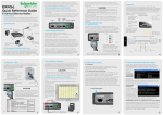
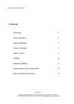
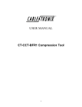
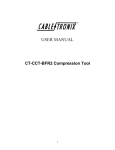
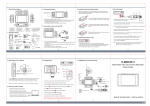
The limited warranty stated herein is subject to all of the following terms and conditions.
William Stump & Associates, LTD
TERMS AND CONDITIONS
1. NOTIFICATION OF CLAIMS: WARRANTY SERVICE: If Purchaser believes that the product is defective in
material or workmanship, then written notice with an explanation of the claim shall be given promptly by
Purchaser to the Manufacturer but all claims for warranty service must be made within the warranty period.
No repair or replacement of any product or part thereof shall extend the warranty period as to the entire
product. The specific warranty on the repaired part only shall be in effect for a period of ninety (90) days
following the repair or replacement of that part or the remaining period of the product parts warranty,
whichever is greater.
2. EXCLUSIVE REMEDY: ACCEPTANCE: Purchaser’s exclusive remedy and the Manufacture’s sole
obligation is to supply all labor necessary to repair any product found to be defective within the warranty
period. Purchaser’s failure to make a claim as provided in paragraph 1 above or continued use of the
product shall constitute an unqualified acceptance of such product and a waiver by Purchaser of all claims
thereto.
WSA-UltraLink 1-Watt Outdoor
Audio/Video Transmitter
User’s Manual
2.4 GHz Wireless - FCC Part 90
3. EXCEPTIONS TO LIMITED WARRANTY: The Manufacturer shall have no liability or obligation to Purchaser
with respect to any product requiring service during the warranty period which is subjected to any of the
following: abuse, improper use, negligence, accident, modification, failure of the end-user to follow the
operating procedures outlined in the user’s manual, failure of the end-user to follow the maintenance
procedures in the service manual for the product, attempted repair by non-qualified personnel, operation of
the product outside of the published environmental and electrical parameters, or if security seal has been
defaced, altered, or removed. The Manufacturer also excludes from warranty coverage products located
outside the United States, and consumable items such as fuses and batteries. Items not manufactured by
Backgrounds Unlimited, Inc but included in system bought by Purchaser are limited to original
manufacturer’s warranty and will be repaired by Backgrounds Unlimited, Inc. on cost of material basis.
4. PROOF OF PURCHASE: The purchaser’s dated invoice must be retained as evidence of the date
of purchase and to establish warranty eligibility.
DISCLAIMER OF WARRANTY
EXCEPT FOR THE FOREGOING WARRANTIES, THE MANUFACTURER HEREBY DISCLAIMS AND EXCLUDES ALL
OTHER WARRANTIES, EXPRESS OR IMPLIED, INCLUDING, BUT NOT LIMITED TO ANY AND/OR ALL IMPLIED
WARRANTIES OF MERCHANTABILITY, FITNESS FOR A PARTICULAR PURPOSE AND/OR ANY WARRANTY WITH
REGARD TO ANY CLAIM OF INFRINGEMENT THAT MAY BE PROVIDED IN SECTION 2-312(3) OF THE UNIFORM
COMMERCIAL CODE AND/OR ANY OTHER COMPARABLE STATE STATUE. THE MANUFACTURER HEREBY
DISCLAIMS ANY REPRESENTATIONS OR WARRANTY THAT THE PRODUCT IS COMPATIBLE WITH ANY
COMBINATION OF NON-MANUFACTURER’S PRODUCTS PURCHASER MAY CHOOSE TO CONNECT TO THE
PRODUCT.
LIMITATION OF LIABILITY
THE LIABILITY OF THE MANUFACTURER, IF ANY, AND PURCHASER’S SOLE AND EXCLUSIVE REMEDY FOR
DAMAGES FOR ANY CLAIM OF ANY KIND WHATSOEVER, REGARDLESS OF THE LEGAL THEORY AND
WHETHER ARISING IN TORT OR CONTRACT, SHALL NOT BE GREATER THAN THE ACTUAL PURCHASE PRICE
OF THE PRODUCT WITH RESPECT TO WHICH SUCH CLAIM IS MADE. IN NO EVENT SHALL THE
MANUFACTURER BE LIABLE TO PURCHASER FOR ANY SPECIAL, INDIRECT, INCIDENTAL, OR
CONSEQUENTIAL DAMAGES OF ANY KIND INCLUDING, BUT NOT LIMITED TO, COMPENSATION,
REIMBURSEMENT OR DAMAGES ON ACCOUNT OF THE LOSS OF PRESENT OR PROSPECTIVE PROFITS OR
FOR ANY OTHER REASON WHATSOEVER.
5
Law Enforcement System
UltraLink 1-Watt Outdoor
Audio/Video Transmitter
2.4 GHz Wireless - FCC Part 90
INTRODUCTION
Congratulations, and thank you for purchasing the
UltraLink 1-Watt Outdoor Audio/Video Transmitter.
This totally contained surveillance system is designed
and manufactured using stringent standards and
customer input. Features Include:
•
•
•
•
•
FCC-approved 2.4 GHz transmitter and receiver
A/C or D/C operation
Readily accepts color or B/W, NTSC or PAL
Easy installation
User-friendly operation
As you read through this manual, please keep in mind
your system has been rigorously inspected for utmost
quality assurance prior to shipment.
About the UltraLink 1-Watt
The UltraLink 1-Watt Outdoor Audio/Video
Transmitter incorporates a FCC-approved
transmitter with a high-impact protective NEMA4rated housing. The result is an extremely
powerful surveillance tool. Designed for outdoor
use, the UltraLink 1-Watt is capable of
transmitting quality audio/video footage up to 30
miles line of sight, depending on the surrounding
environment. Whether you are gathering
evidence, furthering an investigation, or simply
seeking peace of mind, the UltraLink 1-Watt
Outdoor Audio/Video Transmitter will accomplish
your goals.
i
Important Safety Precautions
•
•
•
•
•
To prevent fire or shock hazard, do not expose this
product to rain or moisture. Do not use near a bath
tub, sink, washing machine, or swimming pool. Avoid
locations such as wet basements or any other area
where moisture may cause electric shock.
To avoid electrical shock, do not attempt to open the
case of the UltraLink 1-Watt transmitter or receiver
while in use.
Operate the UltraLink 1-Watt Outdoor Video Transmitter using only the included power supply or other recommended power supply (see “Deployment,” page 12).
Do not overload electrical outlets or extension cords
as this can result in fire or electric shock.
Refer servicing to qualified personnel.
Warranty Information
The manufacturer warrants their products to be free from
defects in material or workmanship for a period of ninety
(90) days from the date of original purchase.
Exceptions on selected products are as follows:
Product
Warranty Coverage
Consumer products
1 year
Pro Consumer Products
2 years
Law Enforcement Grade Products
2 years
If a product has to be returned for repair, it should be returned either in its original carton or similar packaging affording an equal degree of protection. All freight costs
associated with replacement or repair of products are the
responsibility of the Purchaser. The Manufacturer is not
obligated to provide the Purchaser with a substitute unit
during the warranty period or at any time thereafter.
4
Options
If your UltraLink 1-Watt Outdoor Audio/Video Transmitter was ordered
with the optional four-pin wiring harness, use the following procedures
to deploy your transmitter and receiver.
1.
2.
3.
4.
5.
Plug the four-pin cable with BNC video, RCA audio and male
2.1mm power connectors into the four-pin connector on the transmitter (see Figure 3).
At the opposite end of the cable, you will find BNC video and RCA
audio connectors. Connect these to the video and audio outputs of
your camera, respectively. There is also a 2.1mm power connector. Use this to connect the cable to the power input of your camera.
Connect the supplied D/C wiring harness to the transmitter and
power supply as described in “Deployment of the UltraLink 1-Watt
Outdoor Video Transmitter,” found on page 1.
Plug the four-pin cable with BNC video, RCA audio, and female
2.1mm connectors into the four-pin connector on the receiver (see
Figure 3).
At the opposite end of the cable, you will find BNC and male RCA
connectors. Connect these to the video and audio input, respectively, of your monitor or recorder as described in “Using a Monitor” and “Using a Recorder,” found on page 2. There is also a
2.1mm female connector. Use this to connect the cable to either
the provided power supply or another regulated power supply rated
at 12V D/C@500ma.
Figure 3
Optional 4-pin
wiring harness
and connector
Locating the Video Input Button
Depending on the make and model of your monitor or recorder, the
video input button is usually located on the remote control or on the
front panel of the unit itself. However, some units require you to select
your video input within the on-screen menu. The diagram below shows
some examples of remote controls with a video input button. For additional information, consult the owner’s manual for your monitor or recorder.
Table of Contents
General . . . . . . . . . . . . .
1
Pre-Operation . . . . . . . . . .
1
Deployment of Transmitter . . .
1
Deployment of Receiver . . . .
2
Using a Monitor . . . . . . . . .
2
Using a Recorder . . . . . . . .
2
Options . . . . . . . . . . . . .
3
Video Input Button . . . . . . .
3
Safety Precautions . . . . . . .
4
Warranty Information . . . . . .
4
NOTE: This unit is equipped with audio capabilities and is not
intended for covert applications unless in use by sworn Law
Enforcement agencies. It is illegal for non-authorized persons
to own, possess, or utilize surreptitious listening devices for
the purpose of intercepting and/or recording another person’s
oral communications. Any modifications made to this unit are
unauthorized and will immediately void the Manufacturer’s
Warranty.
Part 90 High Power:
THIS EQUIPMENT MAY ONLY BE OPERATED UNDER A PART 90 LICENSE ISSUED BY THE FCC. THE USER IS RESPONSIBLE FOR OPERATING THIS EQUIPMENT IN COMPLIANCE WITH FCC RULES. OPERATION OF THIS EQUIPMENT
WITHOUT A VALID FCC LICENSE COULD RESULT IN THE ISSUANCE OF FINES
TO THE USER OR SEIZURE OF THE EQUIPMENT.
FCC ID Number NH5-FWTX1W
3
Figure 4
ii
General
Deployment of the UltraLink 1-Watt Outdoor Video Receiver
The transmitting antenna, also known as a “directional antenna,” is
located behind the black ABS plastic insert inside of the transmitter unit (4” x
4” x 4” NEMA4 case). The 2.4 GHz antenna on the receiver is located behind
the black ABS plastic insert of the receiver unit (6” x 6” x 4” NEMA4 case) and
faces toward the front of the unit. For optimal performance, the transmitting
antenna should be oriented with the receiving antenna. Although the unit will
still work properly without the units facing each other, the transmission range
may be decreased.
1.
2.
3.
4.
Pre-Operation
1. Read this manual thoroughly before beginning any installation!
2.
Decide on a video source for video input into the transmitter. When
choosing cameras, color cameras perform best during normal daylight
operations, while black & white cameras perform well in low-light, nighttime conditions.
5.
6.
7.
8.
Deployment of the UltraLink 1-Watt Outdoor Video Transmitter
1.
2.
3.
4.
5.
6.
7.
8.
Determine the placement of your transmitting unit and mount to a stable
surface using standard hardware.
Remove the four screws from the face of the transmitter and set aside
the lid.
Use a standard RG59 cable to connect the video output from the video
source to the video input inside the transmitter (see Figure 1). Insert the
cable through the weather-resistant strain-relief and connect with a BNC
connector.
Use a standard RCA cord to connect the audio output from the audio
source to the standard female RCA panel-mount connector inside the
transmitter. Insert the cable through the weather-resistant strain-relief.
Run the provided D/C wiring harness through the second strain-relief.
Connect to the screw terminals inside the transmitter, connecting red to
red and black to black (see Figure 1).
Replace the lid on the transmitter and secure using the four screws.
Plug the included power supply into the nearest 110~115 Volt A/C outlet
and use the 2.1mm connector to connect to the wiring harness.
If you choose to use your own power supply, make certain it is a regulated power supply rated at 12VD/C@1700ma.
12V D/C screw
terminals
+ (red)
- (black)
Video input/
output jack
Determine the placement of your receiving unit and mount to a stable
surface using standard hardware.
Remove the four screws from the face of the receiver and set aside the
lid.
Use a standard RG59 cable and a BNC connector to connect the video
output jack inside the receiver (see Figure 1). Insert the cable through
the weather-resistant strain-relief and connect to the video input jack
on your monitor or recorder (see Figure 2).
Use a standard RCA cable to connect to the audio output jack inside the
receiver. Insert the cable through the weather-resistant strain-relief and
connect to the audio input jack on your monitor or recorder.
Run the provided D/C wiring harness through the second strain-relief.
Connect to the screw terminals inside the receiver, connecting red to
red and black to black (see Figure 1).
Replace the lid on the receiver and secure using the four screws.
Plug the included power supply into the nearest 110~115 Volt A/C outlet and use the 2.1mm connector to connect to the wiring harness.
If you choose to use your own power supply, make certain it is a regulated power supply rated at 12VD/C@500ma.
Using a Monitor
If you wish only to view your video using a standard monitor or television, you
will need to connect your receiver directly to your monitor as follows:
1.
2.
3.
Connect the RG59 cable from the receiver to the video input jack on
your monitor or television using a standard RCA connector.
Change the video input for your monitor accordingly (see Figure 4).
Your monitor should display the view from your camera. Make any necessary adjustments to your transmitter and receiver for best reception.
Using a Recorder
If you wish to record the footage from your camera, you will need to connect
your receiver unit to a VCR or other video recorder as follows:
1.
2.
3.
4.
Connect the RG59 cable from the receiver to the video input jack on
your monitor or television using a standard RCA connector. Always connect equipment to your recorder according to the manufacturer’s instructions.
Change the video input for your recorder accordingly (see Figure 4).
Use a monitor to assure that your video footage is reaching the recorder. Connect the recorder to the monitor using the recorder’s “video
out” jack.
Your monitor should display the view from your camera. Make any necessary adjustments to your transmitter and receiver for best reception.
Audio out to monitor or recorder
Video out to monitor or recorder
Strain reliefs
12 Volt DC power in
Figure 1
1
Figure 2
2