1
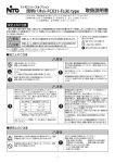
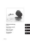
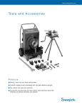
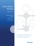
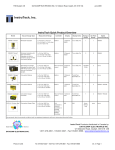
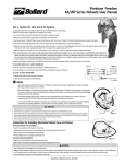
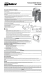
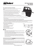
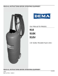
Page 1 of 19
Print/Review Date: 28 April 2003
Contents
Page
Section 1:
Overview
3
Section 2:
Physical Installation
4
Pipe or tubing mounting
Panel mounting
Plumbing Connections
Filtering
Section 3:
Electrical Connections
7
Output Signal waveform
Output Signal amplitude
Section 4:
Flow Response
8
Response Graphs
Calibration
Section 5:
Maintenance
13
Section 6:
General
15
Warranty
Certifications
Trademarks
Section 7:
Reference Documents
15
300/3000 Series Flow Sensor Data Sheet
100 Series Flow Switch Data Sheet
Can we Improve? Tell our President!
Can we improve our product, our support or this manual?
We are committed to continuous improvement and welcome your help. Fax, mail or e-mail your ideas to
me, Jon Heiner.
If you include your phone number, I will give you a personal reply. Or if you prefer, call me on my direct
line.
Phone: (650) 943-4102
Page 2 of 19
Fax: (650) 965-9355
E-mail: [email protected]
Print/Review Date: 28 April 2003
Section 1:
Overview
These products are NOT recommended for inclusion in new designs! Flow sensors with
Hall Effect sensors are better suited for interfacing with current electronic devices.
Refer to the PS600 Series for information or contact Proteus for assistance in selecting
a sensor best suited to your application.
300 & 100XT Series flow sensors provide an output frequency proportional to the flow rate of the liquid
passing through the sensor.
300 Series Flow Sensors include a plastic back cover to enclose the sensing induction coil and provide
two wires for connection to the user’s control circuit.
100xT Flow Transducers are the flow-sensing portion of the 100 Series Flow Switch. The 100XT flow
sensor has no protective cover, and provides 2 spade connectors for quick electrical connection.
300 Series ¼” NPT
Table 1 Flow Ranges & Connections
How do they work?
The rotor spins when liquid flows through the sensor body.
Magnets in the rotor create a voltage in an induction coil mounted
in the sensor body. The amplitude of the induced voltage is at
a maximum when the magnet is immediately adjacent to the coil.
Induction
coil
Rotor
Both the frequency and amplitude of the induced voltage are
proportional to the rotational velocity of the rotor and the linear
velocity of the liquid as it passes through the sensor body.
The amplitude of the voltage generated in the induction coil is a more reliable indicator of flow rate than
frequency.
Page 3 of 19
Print/Review Date: 28 April 2003
Section 2:
Physical Installation
CAUTION!
It is generally undesirable to mount any plumbing connections directly over
electronic controls or instruments.
WARNING!
If the 300 or 100XT Series flow sensor is mounted in a vertical pipeline, any leakage from the
topmost connection could enter the unit and cause permanent damage to the induction coil.
Pipe or tubing mounting
If rigid piping or tubing is used, the 300 and 100XT flow sensor may be supported by direct connection to
the pipe or tubing.
Panel mounting
To mount the sensor behind a panel, two of the faceplate securing screws will need to be replaced with
longer screws to compensate for the thickness of the panel. Ensure that the screws are not so long that
they will touch the bottom of the tapped hole, or rip through the back of a plastic body if over-tightened.
Evenly space up to six holes for 8-32 screws on a 2.5” circle. Using the two holes on the horizontal plane
is usually sufficient to support smaller flow sensors and all plastic sensors. If you wish the rotor to be
visible, cut a 1¾” diameter hole with the same center.
1. Remove screws holding the faceplate to the sensor body.
2. Place the sensor behind the panel and insert the longer screws you have selected.
3. Secure the screws in the body with a torque of ~ 10 in-lb. (Finger tight with a flat-blade
screwdriver.).
Page 4 of 19
Print/Review Date: 28 April 2003
Plumbing Connections
Note
Before connecting a sensor into your fluid line, verify that the normal flow rates expected
in that line are within the operating range of the sensor as shown in Table 1.
Extended use above the rated maximum flow rate of the sensor will reduce its useable life.
Note
It is recommended that connections to the stainless steel flow sensor be made with stainless steel
or materials of similarly chemical inertness to minimize potential corrosion damage.
Note
The flow response of the sensor, and thus its output response may be dependent on the internal
diameter (ID) of an incoming pipe, or the ID of a tube connection.
If the ID of your pipe or tube fitting where it connects to the inlet port is LESS than the value shown in
Table 2, calibration values may be invalid.
Table 2: Minimum ID of pipe or connection for calibrations to be valid.
Note
The flow response of 300 Series flow sensor and the 100XT flow transducers may be dependent on the
form of a device attached to the inlet connection and other closely located up-stream devices.
Elbows, T-pieces, valves and filters located immediately up-stream from the flow sensor can introduce
swirling motion to the liquid flow. The swirling motion reduces the linear velocity of the flow stream.
We recommend that a straight run of pipe of more than 10 x pipe ID be used between the flow sensor
and any up-stream devices to minimize these effects.
Page 5 of 19
Print/Review Date: 28 April 2003
Note (continued)
Appropriate calibration procedures must be used to provide an accurate flow measurement with elbows
or T-pieces that must be attached directly to the inlet connection.
The 300 and 100XT Series sensors are typically unaffected by the form or proximity of devices on their
downstream side.
Sensor Orientation
For the best results, 300 Series flow sensors and 100XT flow transducers should be mounted with the
faceplate in the vertical plane.
Mounting the device with the flow connections uppermost can help eliminate entrained air from your
system.
Flow Direction
The polarity of the output voltage is dependent on flow direction. Some sensors can be operated in only
one direction, as shown below.
304L
301
303
350
355
360
370
Model #
104XT
101XT
103XT
150XT
155XT
160XT
170XT
Flow Path Direction
A to B only
A to B only
D to C or C to D
D to C only
D to C or C to D
D to C or C to D
D to C or C to D
Table 2: Allowed flow directions
NPT pipe thread connections
Pipe threads seal by making metal-to-metal or plastic-to-plastic contact between male and female
components. Consequently they are particularly prone to the damaging effects of galling, which occurs
when two surfaces move against each other under pressure. When installing pipe threads it is essential
to use a high quality lubricating and sealing material.
WARNING
Do NOT use anaerobic pipe sealants such as LOCTITE or SWAK
brand sealants with these sensors.
The aggressive chemical nature of these materials can cause
cracking of the polysulfone faceplate.
•
Use Teflon tape or a PTFE-based liquid sealant to provide lubrication for the junction and a leak-tight
connection at both input and output connections. Real-Tuff and Hercules are two of many suitable
brands of PTFE-based sealants.
•
Do not over-tighten the connection. Refer to instructions for installation of the mating fittings for
information on torque requirements.
Page 6 of 19
Print/Review Date: 28 April 2003
•
Leak testing of all connections in your flow circuit is recommended. Pressurizing the system with air
and external testing with a dilute soap solution can help identify leaking connections.
Filtering
Your circulating fluid may contain particles. While not essential to the operation of the flow sensor, it is
good practice to filter your fluid. A 100-micron filter is often used to remove rust and other particles from
the fluid. This can increase the lifetime of pumps and other fluid system components as well as reducing
wear in the sensor.
Fluid Temperature Range
Flow sensors with plastic bodies should not be used above 75°C. Metal bodies with metal faceplates may
be used with liquids to higher temperatures. The induction coil should not be used for temperatures
above 110°C.
For higher temperature situations, contact Proteus Applications for assistance in selecting the flow sensor
best suited to your application.
Section 3:
Electrical Connections
Note
Only personnel familiar with the electrical circuit and control functions of the system in which
the sensors are to be included should perform installation of this product.
The 100XT transducer provides two male spade-type quick disconnects to connect to the coil output. Two
matching female connectors (Panduit P/N DNF1 8-206Fl B-M) are shipped with each transducer.
300 Series Flow Sensors have a 2 wire cable connecting to the coil output. The signal wire color codes are
clear and black.
Output Signal
The output signal is the voltage generated by the magnets in three spokes of the rotor passing by the pickup
coil.
The waveform varies somewhat with flow rate. It is similar, but not identical to a rectified sine wave. A typical
waveform is shown below.
Page 7 of 19
Print/Review Date: 28 April 2003
Doc No: 620300-002
Review Date: 28 April 2003
Technical Reference Manual for 300 & 100XT Flow Sensors
NOTE
The electrical polarity of the coil output is sensitive to the direction of flow through
the sensor body. Some user-designed electronics may be sensitive to the
polarity.
The polarity of the output signal can be reversed by reversing the connections at
the induction coil of the 100XT transducer, or reversing the wire connections of
the 300 Series Flow Sensor.
Output Amplitude
The amplitude of the output signal increases with frequency. A typical output response is shown below.
0.60
Output - VDC
0.50
0.40
0.30
0.20
0.10
0.00
0
20
40
60
80
Frequency - Hz
100
120
Figure 1: Typical output response
Section 4:
Flow Response
The typical response curves for 300 and 100XT Series sensors are illustrated.
NOTE
These response curves were collected with Schedule 40 brass or polypropylene pipes threaded directly
into the appropriate inlet ports. Table 2 above shows the ID's of pipes used to obtain the reference flow
response data.
Proteus sensors are sensitive to the internal inside diameter (ID) of the pipe or hose connection at the
inlet port.
Connections that have ID’s less than that of Schedule 40 pipe will provide a HIGHER response.
Connections that have ID’s greater than that of Schedule 40 pipe or introduce swirling motion into the
liquid stream will provide a LOWER response.
Page 8 of 19
Print/Review Date: 28 April 2003
Doc No: 620300-002
Review Date: 28 April 2003
Technical Reference Manual for 300 & 100XT Flow Sensors
Page 9 of 19
Print/Review Date: 28 April 2003
Doc No: 620300-002
Review Date: 28 April 2003
Technical Reference Manual for 300 & 100XT Flow Sensors
Page 10 of 19
Print/Review Date: 28 April 2003
Doc No: 620300-002
Review Date: 28 April 2003
Technical Reference Manual for 300 & 100XT Flow Sensors
Page 11 of 19
Print/Review Date: 28 April 2003
Doc No: 620300-002
Review Date: 28 April 2003
Technical Reference Manual for 300 & 100XT Flow Sensors
Page 12 of 19
Print/Review Date: 28 April 2003
Doc No: 620300-002
Review Date: 28 April 2003
Technical Reference Manual for 300 & 100XT Flow Sensors
Calibration
Measurement of the actual response from an installed sensor is necessary to achieve an accurate response
curve. Calibration by Proteus is available for devices with simple, small connections. Contact Proteus
Applications for assistance.
Section 6:
Maintenance
Maintenance of the sensor is normally limited to cleaning the chamber in which the rotor spins and annual
recalibration.
The frequency of cleaning will vary with the type of fluid being run and the cleanliness of that fluid.
In most cases, annual cleaning immediately prior to recalibration is sufficient.
Cleaning the 300 Series Flow Sensor & 100XT Flow Transducers
1. Turn OFF the liquid flow in your flow
circuit and remove the flow sensor or
transducer sensor from your system.
Place the unit on a clean surface.
2. Remove the 6 screws securing the
faceplate.
3. Remove the faceplate from the flow meter.
Page 13 of 19
Print/Review Date: 28 April 2003
Doc No: 620300-002
Review Date: 28 April 2003
Technical Reference Manual for 300 & 100XT Flow Sensors
Cleaning the 300 Series Flow Sensor & 100XT Flow Transducers
4. Remove the rotor and stainless steel shaft
from the flow cavity.
Remove the O-ring from the faceplate
5. Using a soft cloth dampened with water, alcohol or a light detergent solution, clean debris and dirt
from the rotor, the stainless steel shaft, the inside surfaces of faceplate and the surfaces of the flow
cavity
6. Inspect the bearing surface of the rotor.
If the bearing surface is worn or not round, replace the rotor.
Inspect the stainless steel shaft.
If the shaft shows signs of scoring or other wear, replace the shaft or the whole faceplate assembly.
7. Inspect the O-ring to ensure that it is not
brittle, cracked or otherwise damaged.
If necessary replace with a #132 O-ring of a
material compatible with the liquid being
passed through the flow meter.
Position the O-ring on the inner rim of the
faceplate.
8. Place the rotor in the flow cavity.
Position the shaft (or the faceplate) to locate
the shaft in the rotor.
Page 14 of 19
Print/Review Date: 28 April 2003
Doc No: 620300-002
Review Date: 28 April 2003
Technical Reference Manual for 300 & 100XT Flow Sensors
Cleaning the 300 Series Flow Sensor & 100XT Flow Transducers
9. Position the faceplate so that the holes
in the faceplate are aligned with the screw
holes in the front of the flow sensor body.
Replace the 6 securing screws.
Tighten the screws to a torque of 10 in-lbs
(hand tighten with a normal screwdriver).
11. Install the flow meter in your system.
Turn on liquid flow and check for leaks at the faceplate and connecting ports.
Tighten all connections as required to eliminate leaks.
Section 7:
General
Proteus 5-Year Warranty
A full statement of our Warranty is available at our website, www.Proteusind.com
Certifications
300 & 100XT Series products are rated under the German Bauart standards as
Installation Category 11, not for Heavy Industrial installation.
They are Class 11 devices, no earth ground provided.
Trademarks
Celcon, Nylon and Kynar are registered trademarks of Celanese Plastics, DuPont and Elf-Autochem. Real-Tuff,
Hercules, Loctite and SWAK are trademarks of their respective holders.
Page 15 of 19
Print/Review Date: 28 April 2003
Doc No: 620300-002
Review Date: 28 April 2003
Technical Reference Manual for 300 & 100XT Flow Sensors
Section 7:
Reference Data Sheets & Specifications
300/3000 Data Sheet & Specifications
Page 16 of 19
Display is no longer available. Do not include this in new designs.
Print/Review Date: 28 April 2003
Doc No: 620300-002
Review Date: 28 April 2003
Technical Reference Manual for 300 & 100XT Flow Sensors
300/3000 Data Sheet & Specifications
Page 17 of 19
Print/Review Date: 28 April 2003
Doc No: 620300-002
Review Date: 28 April 2003
Technical Reference Manual for 300 & 100XT Flow Sensors
100 & 100XT Data Sheet & Specifications (220 volt is no longer available)
Page 18 of 19
Print/Review Date: 28 April 2003
Doc No: 620300-002
Review Date: 28 April 2003
Technical Reference Manual for 300 & 100XT Flow Sensors
100 & 100 XT Data Sheet
Page 19 of 19
Print/Review Date: 28 April 2003