1
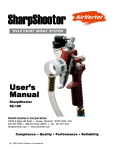
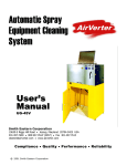
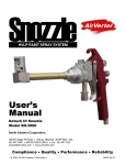
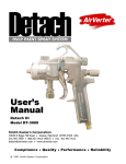
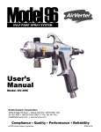
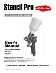
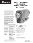
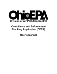
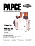
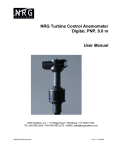
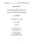
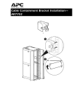
CAPTURED AIR POLLUTANTS SYSTEM
User’s Manual
U.S. Patents 7,550,022
Smith Eastern Corporation
10630-S Riggs Hill Road • Jessup, Maryland 20794-9425 USA
301.497.7600 • 800.937.HVLP (4857) • Fax 301.497.7613
[email protected] • www.airverter.com
Compliance • Quality • Performance • Reliability
©2008 Smith Eastern Corporation
2010-01-22
AirVerter® Captured Air Pollutants Sytem
Please Read User's Manual BEFORE
Using This Equipment
WHEN IN THE PROXIMITY OF HAZARDOUS FUGITIVE EMISSIONS
USE PROPER PERSONAL SAFETY.
WARRANTY
Smith Eastern Corporation warrants to the Purchaser that Captured Air Pollutants System (CAPS) is
free from defects in material or workmanship under normal use and service for a period of twelve (12)
months from the date of shipment.
Should any failure appear during this period, Smith Eastern shall, if given prompt written notice by the
Purchaser, correct such nonconformity by repair or replacement of the nonconforming part, F.O.B.
Smith Eastern’s repair facility. Repair parts are warranted for ninety (90) days from the date of
shipment, but repairs or replacements to original equipment shall not renew or extend the warranty
period of such equipment.
Equipment and parts furnished by Smith Eastern but manufactured by others shall be limited to the
warranty offered by the manufacturer thereof.
Smith Eastern reserves the right to limit this warranty in cases of misuse or abuse. Any modifications
to equipment or recommended procedures will void the warranty.
The foregoing warranty is exclusive and in lieu of other warranties of quality or performance,
expressed, implied or statutory, including any warranties of merchantability or of fitness for a particular
purpose.
USE PERSONAL SAFETY EQUIPMENT AROUND HAZARDOUS EMISSIONS
1
AirVerter® Captured Air Pollutants System
How CAPS II Works
Upon atomization (1) the coating is
contained within the cone (2).
Overspray and fumes are collected
and evacuated through the Intake
Hose (3) and directed into the Filter
Housing (4). The contaminated air is
then processed through a NESHAP
Compliant Filter Arrangement (5) and
expelled through the Exhaust Hose
(6) using a Pneumatic AirFlow
Device in the Controller Unit (7). The
air may then be discharged into the
workplace or directed through an
Exhaust Duct (8).
2
Containment
Cage
(Double Cone)
1
Atomizer
5
NESHAP
Compliant
Filters
Prefilter
3
Intake
Hose
4
HEPA
Filter Housing
6
Exhaust
Hose
8
Exhaust Duct
7
Pneumatic
Air-Flow
Generator
2
USE PERSONAL SAFETY EQUIPMENT AROUND HAZARDOUS EMISSIONS
AirVerter® Captured Air Pollutants System
Set-up
The CAPS II System consists of a Controller Unit
(CA-100), Filter Unit (CA-075), Containment
Cone Assembly (CA-070), Intake Hose (CA-060),
and an Exhaust Hose (CA-050)
A. Open the Filter Unit and remove the
protective covering from the Carbon Filter.
Replace the Carbon Filter in the Filter Unit
and close the Filter Unit
B. Attach the Intake Hose to the intake port of
the Filter Unit
C. Attach one end of the Exhaust Hose to the
exhaust port of the Filter Unit and the other
end to the intake port on the Controller Unit.
Attach grounding wires to the grounding lugs
D. Connect the pressurized air supply to the Air
Intake Fitting on the Controller Unit.
E. Attach the Containment Cone to the Intake
Hose.
F. Connect the Air Hose from the Controller Unit
to the Spray Gun.
G. If needed, an additional Exhaust Hose (not
included) can be connected to the Controller
unit to duct exhausted air further away from
the workplace.
OPERATION
After completing the set-up and
before operation:
A. Turn on Pressurized Air Supply to the unit.
B. Adjust the pattern size and atomizing air
pressure so that it does not impinge on the
cone walls
C. Adjust Vacuum Pressure to remove
overspray and odors without distorting spray
pattern.
C. If overspray/fumes are being blown out of
the containment area, increase vacuum, or
reduce atomizing air pressure/fluid volume
Spraying
A. When
spraying,
hold
the
cone
approximately ½-1 inch from the surface
being sprayed to achieve maximum
containment/evacuation.
B. Maintain the cone as parallel to the
substrate as possible. Tilting the cone will
cause overspray and fumes to escape the
containment area.
USE PERSONAL SAFETY EQUIPMENT AROUND HAZARDOUS EMISSIONS
3
AirVerter® Captured Air Pollutants System
CA-100 Controller Unit
CA-300 Spray Gun
CA-075 Filter Unit
CA-070 Containment Cone
CA-050 Vacuum Hose
CA-051 Collection Hose
ILLUSTRATED PARTS BREAKDOWN
4
Part #
NSN
Description
CA-037
-
Pre-Filter
CA-038
-
HEPA Filter
CA-039
-
Carbon Filter
CA-050
-
Vacuum Hose w ends
CA-051
-
Collection Hose w ends
CA-070
-
Containment Cone Assembly
CA-071
-
Containment Cone (replacements)
CA-075
-
Filter Unit
CA-081
-
CAPS Cart
CA-100
-
Controller Unit
CA-300
-
CAPS Spray Gun
USE PERSONAL SAFETY EQUIPMENT AROUND HAZARDOUS EMISSIONS
AirVerter® Captured Air Pollutants System
TO REMOVE THE CONTAINMENT CONES:
A. Loosen the air-regulating valve to allow the
Containment Cone Gun Adapter to pivot
slightly
B. Insert the metal probe under the snap ring
and gently lift the ring from the groove by
moving the probe around the Air Cap
Retaining Ring. Once the snap ring is free
remove the inner and outer cones, taking
care not to lose the snap ring.
TO REPLACE THE CONTAINMENT CONES:
A. Place the outer and inner cones over the Air Cap
Retaining Ring. Place the snap ring over the air cap
and with the tool provided, gently push the snap ring
into place using a slight rocking motion
B. Insert the Containment Cone Gun Adapter into
the exhaust port of the Outer Containment Cone.
C. Tighten the Air Regulating Valve securing the
Containment Cone Gun Adapter to the spray gun.
USE PERSONAL SAFETY EQUIPMENT AROUND HAZARDOUS EMISSIONS
5
AirVerter® Captured Air Pollutants System
ACTIVATED CARBON FILTER
Carbon Filters are designed for odor removal
only. They are not for particulate collection.
Odor removal is a direct function of the amount
of carbon exposed to the air stream.
Carbon filters are designed for light to moderate
odor conditions in multi-stage filtration systems
where other filters are installed upstream from
the carbon filters.
Each filter is sealed to prevent adsorption from
occurring prior to installation.
Other filters are necessary to remove
particulate contaminants from the air to prevent
coating the microscopic carbon pore structure.
TROUBLESHOOTING
Problem
No/Low Air Flow
6
Probable Cause
Remedy
1. Filter Clogged
1. Replace Clogged Filter
2. Ducts Blocked
2. Remove Blockage
USE PERSONAL SAFETY EQUIPMENT AROUND HAZARDOUS EMISSIONS
AirVerter® Captured Air Pollutants System
USING CAPS WITH PAPCE
To use the CAPS spray gun with a PAPCE system, attach
the Collection Hose to the port on the Motor Starter end of
the PAPCE. Ensure that both of the ducts on the PAPCE
collection arms are open.
You may use the CAPS system alone or in conjunction with the PAPCE collection arms
USE PERSONAL SAFETY EQUIPMENT AROUND HAZARDOUS EMISSIONS
7