1
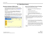
Procom PPC Software
User’s Manual
Version 1.1
Notice:
The ECU has been programmed and is READY TO USE
WITHOUT reprogramming. Just PLUG IN & GO.
However, if you are determined to reprogram it, you have to read
through this manual and follow the procedures. The basic computer and
dyno tuning knowledge is required. The 3D combination maps are
already built in; you are only able to adjust the maps based on the
Procom default “0” baseline. In addition, you can select a map from our
CD kit or free download more maps from our web site:
www.procomeng.com.
Procom Engineering Inc.
66 Maxwell, Irvine, CA 92618, USA
Tel: 949-748 6338 Fax: 949-748 6339
Email: [email protected]
www.procomeng.com
Contents
1.
1.1
1.2
1.3
2.
2.1
2.2
3.
3.1
3.2
3.3
3.4
3.5
3.6
3.7
3.8
4.
4.1
4.2
4.3
4.4
4.5
4.6
4.7
4.8
4.9
4.10
4.11
4.12
4.13
4.14
4.15
General................................................................................................................. 2
Procom programmable ECU kit............................................................................ 2
How to connect ECU for programming................................................................. 2
Operation system requirement .............................................................................. 2
How to Install Procom PPC Driver ....................................................................... 3
Step 1 ................................................................................................................... 3
Step 2 ................................................................................................................... 4
How to Install Procom PPC Software ................................................................... 5
Step 1 ................................................................................................................... 5
Step 2 ................................................................................................................... 6
Step 3 ................................................................................................................... 7
Step 4 ................................................................................................................... 8
Step 5 ................................................................................................................... 9
Step 6 ................................................................................................................. 10
Step 7 ................................................................................................................. 11
Step 8 ................................................................................................................. 12
How to Use Procom PPC Software..................................................................... 13
Description of functions under “Program” .......................................................... 14
Description of functions under “Preview”........................................................... 16
How to add point to create your map .................................................................. 17
How to modify a point from a map ..................................................................... 18
How to create another function data.................................................................... 19
FUEL vs. RPM function ..................................................................................... 20
TIMING vs. RPM function................................................................................. 21
FUEL vs. TPS function....................................................................................... 22
TIMING vs. TPS function .................................................................................. 23
FUEL vs. ECTS function.................................................................................... 24
TIMING vs. IAPS function................................................................................. 25
REV. LIMIT function......................................................................................... 26
How to preview and save your function data....................................................... 27
How to delete and export a saved map ................................................................ 28
How to send data to ECU ................................................................................... 29
1
1. General
This software is designed for end users to re-program the Procom ECU to achieve
maximum performance or enhance personalization. This simple but powerful software
allows you to edit the data in ECU, write new data into ECU or reset the default to ECU.
It applies for Procom ECU models 2009 or later.
You are advised to read this manual carefully before you attempt to re-program Procom
ECU. You may want to check our website to see whether there is a newest edition or
update of this manual since it was printed.
1.1 Procom programmable ECU kit
The Procom programmable ECU kit comes with Procom engine control unit (ECU),
Procom Programmable Power Curves (PPC) software CD and a USB cable.
The ECU has been programmed at the default status and is ready to use WITHOUT your
effort to program it. However, if you are determined to reprogram it, you have to read
through this manual and follow the procedures as follows.
1.2 How to connect ECU for programming?
Before you start programming your ECU, you have to connect Procom ECU with your
computer through the USB cable we provided. Plug one end of the USB cable into your
computer USB port and connect the other end to Procom ECU.
1.3 Operation system requirement:
Windows 2000 or newer excluding Windows Vista.
Resolution of Display: 1024x768 or higher.
P.S.
(1). If you have limited dyno tuning knowledge but still wish to increase the Rev. limit,
you may do so without changing Procom default “0” baseline maps.
(2). The standard Procom PPC software is for various models of ECU, just ignore the
rang of RPM if it is beyond your machine’s Rev. Limit.
Disclaimer: As these products are high performance parts and will increase the
performance of your machine, purchase and use of our high performance parts are at your
own risk. By purchasing and use these parts, our maximum liability is the amount you
paid for the item.
2
2. How to Install Procom PPC Driver?
Before you begin installation of this driver, please make sure that the ECU is not
connected with your computer.
2.1 Step 1
Insert the CD into your CD-ROM. Open the CD and double click on Procom Driver
Installer.exe. The InstallShield Wizard will appear as below.
Click on “Next” to continue…until the following appears.
3
2.2 Step 2
Click “Finish” to complete this installation.
Notes:
If the driver was not installed successfully or does not work properly with your ECU,
then follow the steps below to re-install it:
(1). Disconnect the ECU with your computer.
(2). Uninstall the PL-2303 USB-Serial Driver from your computer.
(3). Restart your computer.
(4). Re-install the driver.
4
3. How to Install Procom PPC Software?
Procom PPC Software is designed for end users to re-program the Procom ECU to
achieve maximum performance or enhance personalization. This simple but powerful
software allows you to edit the data in ECU, write new data into ECU or reset the default
to ECU.
3.1 Step 1
Insert the CD into your CD-ROM. Open the CD and double click on ProcomPPC
Setup.exe until the following appears:
Select your preferred language and click “Next” to go to next step…
5
3.2 Step 2
Make sure that all other programs have been closed in your computer, and then click
“Next” to continue…
6
3.3 Step 3
If you like to install this software into the default directory as appears, just click “Next”
to go to next step…Otherwise, click “Browse” to select a different directory you prefer
and then click “Next” to continue…
7
3.4 Step 4
This setup will add the “ProcomPPC” folder into your computer. You may type a
different name of the folder or select one from the list of Existing Folders. Then click
“Next” to go to next step…
8
3.5 Step 5
If you like to create a shortcut on your desktop and create a quick launch toolbar, just
click “Next” to go to next step…Otherwise, select your preference and then click “Next”
to continue…
9
3.6 Step 6
The Setup is ready to copy the files into your computer, click “Next” to wait for the
following appears…Otherwise, click “Cancel” to quit Setup or click “Back” to
review/change your settings, and then click “Next” to wait for the following appears…
10
3.7 Step 7
Click “Finish” to complete the setup…
11
3.8 Step 8
Congratulations! Procom PPC software has been installed successfully in your computer.
Its copyright is protected by laws. Click “OK” to exit the installation.
12
4. How to Use Procom PPC Software?
Before re-programming your ECU:
(1). Please make sure the ECU is disconnected from the wire harness of your machine or
make sure that your machine’s ignition is turned off! Programming with ignition powered
on may damage the ECU!
(2). The voltage of the sensors is very sensitive. We strongly recommend that you
measure the sensor’s existing voltage of your machine before this programming.
13
4.1 Description of functions under “Program”
FUEL vs. RPM:
You can increase/decrease the fuel against the Revolution Per
Minute (RPM).
TIMING vs. RPM: You can increase/decrease the timing degree against the Revolution
Per Minute (RPM).
FUEL vs. TPS:
You can increase/decrease the fuel against the Throttle Position
Sensor (TPS).
TIMING vs. TPS: You can increase/decrease the timing degree against the Throttle
Position Sensor (TPS).
FUEL vs. ECTS:
You can increase/decrease the fuel against the Engine Coolant
Temperature Sensor (ECTS).
TIMING vs. IAPS: You can increase/decrease the timing degree against the Intake Air
Pressure Sensor (IAPS).
REV. LIMIT:
You can click the up/down arrows to increase/decrease the
Revolution
Limit
as
you
desire.
The
maximum
increment/decrement is +3000/-3000RPM.
Warning: Please consult with your local dealer before you do this.
The over increment of Rev. Limit can damage your machine. Do
this at your own risk!
Message:
Shows your current status.
14
Map:
0-Default:
XXXXXXX-XX:
-01
-02
-03
-04
-05
-06
-07
-08
-09
-10
Import Map:
ENTER:
RESET:
The map is a file folder containing above 6 colored functional data.
It is savable, transferable and restorable. However, for your safety,
the Rev. Limit data is NOT savable, transferable or restorable.
The map is Procom’s manufacturing default map.
The “XXXXXXX” is for Procom ECU P/N, e.g. PE-E-AP800-A.
Map 01 is designed for beginning riders on stock machine.
Map 02 is designed for medium-level riders on stock machine.
Map 03 is designed for advanced riders on stock machine.
Map 04 is designed for beginning riders on minor modified machine.
Map 05 is designed for medium-level riders on minor modified machine.
Map 06 is designed for advanced riders on minor modified machine.
Map 07 is designed for beginning riders on general modified machine.
Map 08 is designed for medium-level riders on general modified machine.
Map 09 is designed for advanced riders on general modified machine.
Map 10 is designed for riders on aggressively modified machine.
You can import Procom PPC maps from any folders in your
computer including the maps you downloaded.
You can drag the color line to edit the data. Or you can input data
by your keyboard and then press ENTER to edit the map.
Click this to reset the edited data to base line “0”.
15
4.2 Description of functions under “Preview”
REV. LIMIT:
Send to ECU:
Save As:
Shows the RPM of the Rev. Limit you just changed.
Click this button to send the data in this preview to the ECU.
Click this button to save the data in this preview as your preference.
16
4.3 How to add a point to create your map?
Open Procom PPC from the shortcut on your desktop or the folder you saved.
Click the colored button on the left to select which function tool you need to create your
map now. Then drag the color line to the point for the data you want. At same time, the
boxes below will show you the exact numeric values as you pointed. Once you release
your mouse, the pointed data will be saved, and then you can create next point. Or you
can manually input the numeric values to the boxes, then click ENTER, the data will be
saved. At same time, the color line will move to the point according to the data you just
entered.
17
4.4 How to modify a point from a map?
Click a point you want to modify, hold and drag it to a new point you desire and then
release. Or you can click RESET button to start over again from the base line.
18
4.5 How to create another function data?
After you have finished creating one function data, such as, FUEL vs. RPM, then you just
click the left colored function button to start creating a new function data, such as, FUEL
vs. TPS. The previous function data you have just created is automatically saved.
19
4.6 FUEL vs. RPM function
Once you click the red function button, the red line will appear. Then you can drag the
red line to set up the data. At the same time, the box after “RPM” will indicate the
numeric value of the RPM and the box after “Fuel %” will indicate the percentage of the
fuel you want to increase/decrease while you drag the red line. Or you can manually input
the numeric values to the boxes, then click ENTER, and the data will be saved. At the
same time, the red line will move to the point according to the data you just entered.
The numbers after the “RPMx1000” indicate engine RPM. The entering of RPM is
multiple of 100 and the maximum RPM is 15,000. The numbers above the “FUEL
Increase/Decrease %” indicate the fuel percentage you want to increase/decrease based
on the built-in default value by the manufacturer, Procom. The maximum increment is
80% and the maximum decrement is 20%.
20
4.7 TIMING vs. RPM function
Once you click the pink function button, the pink line will appear. Then you can drag the
pink line to set up the data. At the same time, the box after “RPM” will indicate the
numeric value of the RPM and the box after “DEGREE” will indicate the timing degree
you want to advance/retard while you drag the pink line. Or you can manually input the
numeric values to the boxes, then click ENTER, and the data will be saved. At the same
time, the pink line will move to the point according to the data you just entered.
The numbers after the “RPMx1000” indicate engine RPM. The entering of RPM is
multiple of 100 and the maximum RPM is 15,000. The numbers above the “DEGREE”
indicate the timing degree you want to advance/retard based on the built-in default value
by the manufacturer, Procom. The maximum advancement is 32 degrees and retardation
is 10 degrees.
21
4.8 FUEL vs. TPS function
Once you click the blue function button, the blue line will appear. Then you can drag the
blue line to set up the data. At the same time, the box after “Voltage” will indicate the
numeric value of the TPS voltage and the box after “Fuel %” will indicate the percentage
of the fuel you want to increase/decrease while you drag the blue line. Or you can
manually input the numeric values to the boxes, then click ENTER, and the data will be
saved. At the same time, the blue line will move to the point according to the data you
just entered.
The numbers before “(V)” indicate TPS voltage. The maximum voltage is 5V. The
numbers above the “FUEL Increase/Decrease %” indicate the fuel percentage you want
to increase/decrease based on the built-in default value by the manufacturer, Procom. The
maximum increment is 80% and the maximum decrement is 20%.
22
4.9 TIMING vs. TPS function
Once you click the light blue function button, the light blue line will appear. Then you
can drag the light blue line to set up the data. At the same time, the box after “Voltage”
will indicate the numeric value of the TPS voltage and the box after “Degree” will
indicate the timing degree you want to advance/retard while you drag the light blue line.
Or you can manually input the numeric values to the boxes, then click ENTER, and the
data will be saved. At the same time, the light blue line will move to the point according
to the data you just entered.
The numbers before “(V)” indicate TPS voltage. The maximum voltage is 5V. The
numbers above the “DEGREE” indicate the timing degree you want to advance/retard
based on the built-in default value by the manufacturer, Procom. The maximum
advancement is 32 degrees and retardation is 10 degrees.
23
4.10 FUEL vs. ECTS function
Once you click the green function button, the green line will appear. Then you can drag
the green line to set up the data. At the same time, the box after “Voltage” will indicate
the numeric value of the ECTS voltage and the box after “Fuel %” will indicate the
percentage of the fuel you want to increase/decrease while you drag the green line. Or
you can manually input the numeric values to the boxes, then click ENTER, and the data
will be saved. At the same time, the green line will move to the point according to the
data you just entered.
The numbers before “(V)” indicate ECTS voltage. The maximum voltage is 5V. The
numbers above the “FUEL Increase/Decrease %” indicate the fuel percentage you want
to increase/decrease based on the built-in default value by the manufacturer, Procom. The
maximum increment is 80% and the maximum decrement is 20%.
24
4.11 TIMING vs. IAPS function
Once you click the light green function button, the light green line will appear. Then you
can drag the light green line to set up the data. At the same time, the box after “Voltage”
will indicate the numeric value of the IAPS voltage and the box after “Degree” will
indicate the timing degree you want to advance/retard while you drag the light green line.
Or you can manually input the numeric values to the boxes, then click ENTER, and the
data will be saved. At the same time, the light green line will move to the point according
to the data you just entered.
The numbers before “(V)” indicate IAPS voltage. The maximum voltage is 5V. The
numbers above the “DEGREE” indicate the timing degree you want to advance/retard
based on the built-in default value by the manufacturer, Procom. The maximum
advancement is 32 degrees and retardation is 10 degrees.
25
4.12 REV. LIMIT function
After editing the colored functional data, if you intend to change your machine’s
Revolution Limit, then you can go to the grey “REV. LIMIT” section and click the
up/down arrows to increase/decrease the revolution limit as you desire. The maximum
increment/decrement is +2500/-2500RPM. The value you selected to appear in the box
will be automatically saved if you go to the next step.
Warning: Please consult with your local dealer before you do this. The over increment
of Rev. Limit can damage your machine. Do this at your own risk!
26
4.13 How to preview and save your function data?
After you have completed creating your functional data and selected REV. LIMIT
increment/decrement value, you can click the Preview button to review all the data you
created. Then you can click the Program button to re-edit it if you want to make further
changes or save it as a new map file if you are satisfied.
27
4.14 How to delete and export a saved map?
If you intend to delete a saved map, click the “Program”, select the file name from the list
in the box under the “MAP” shown in the picture above, then right click the mouse and
click the “Delete”. The map will be deleted permanently!
If you intend to export a saved map, click the “Program”, select the file name from the
list in the box under the “MAP” shown in the picture above, then right click the mouse
and click the “Export”, give a new name and save it to a new location.
28
4.15 How to send data to ECU?
You can send currently previewed data to ECU. Or you can open a saved map from your
computer to preview first and then send to ECU.
After you have previewed the data, make sure that the ECU is connected properly with
your computer. Then you can click Send to ECU button to transfer the data to Procom
ECU.
Once you click the Send to ECU button, a small window will pop up for you to confirm
the changes of Revolution Limit. Please read carefully the message in the box below.
Please compare and be aware of the OEM ECU RPM and the existing Procom ECU RPM.
Then click Yes to confirm or click No to cancel. (Warning: The over Revolution Limit
can damage your machine!)
When the message shows: Data has been transferred to ECU successfully…, which
means that the new data has already overwritten the previous data in the ECU. Your
updated ECU is ready for use now.
Notes:
(1). During transferring of the data to ECU, if the message indicates “Failed connecting
29
to ECU. Please re-check if all the connections are correct and proper…”, please re-check
if all the connections between ECU and your computer are correct and proper. Then try
again.
(2). During transferring of the data to ECU, if the message indicates “Failed connecting
to ECU. Turn off the ignition and try again…”, please turn off the ignition of your
machine promptly. Then try again.
Copyright 2009
Procom Engineering Inc.
30