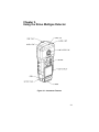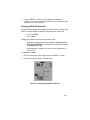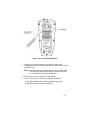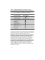
1
SiriusTM
MultiGas Detector
Operating Manual
© MINE SAFETY APPLIANCES COMPANY 2004 - All Rights Reserved
This manual is available on the internet at www.msanet.com
Manufactured by
MSA INSTRUMENT DIVISION
P.O. Box 427, Pittsburgh, Pennsylvania 15230
(L) Rev 0
10048887
º WARNING
THIS MANUAL MUST BE CAREFULLY READ BY ALL INDIVIDUALS WHO HAVE OR WILL
HAVE THE RESPONSIBILITY FOR USING OR SERVICING THE PRODUCT. Like any piece
of complex equipment, this instrument will perform as designed only if it is used and serviced in accordance with the manufacturer’s instructions. OTHERWISE, IT COULD FAIL TO
PERFORM AS DESIGNED AND PERSONS WHO RELY ON THIS PRODUCT FOR THEIR
SAFETY COULD SUSTAIN SEVERE PERSONAL INJURY OR DEATH.
The warranties made by Mine Safety Appliances Company with respect to the product are
voided if the product is not used and serviced in accordance with the instructions in his
manual. Please protect yourself and others by following them. We encourage our customers to write or call regarding this equipment prior to use or for any additional information relative to use or repairs.
i
Table of Contents
Chapter 1,
Instrument Safety and Certifications . . . . . .1-1
º WARNING . . . . . . . . . . . . . . . . . . . . . . . . . . . . .1-1
Safety Limitations and Precautions . . . . . . . . . . . . . . . .1-2
º WARNING . . . . . . . . . . . . . . . . . . . . . . . . . . . . .1-2
Date of Instrument Manufacture . . . . . . . . . . . . . . . . . . .1-4
Certifications . . . . . . . . . . . . . . . . . . . . . . . . . . . . . . . . . .1-4
Electronic Interference . . . . . . . . . . . . . . . . . . . . . . . . . .1-4
Chapter 2, PID Theory and Definitions . . . . .2-1
PID Theory . . . . . . . . . . . . . . . . . . . . . . . . . . . . . . . . . . .2-1
Figure 2-1. Typical Photoionization Sensor Design .2-1
Zero Gas . . . . . . . . . . . . . . . . . . . . . . . . . . . . . . . . . . .2-2
Span Gas . . . . . . . . . . . . . . . . . . . . . . . . . . . . . . . . . . .2-2
Response Factors . . . . . . . . . . . . . . . . . . . . . . . . . . . .2-2
º WARNING . . . . . . . . . . . . . . . . . . . . . . . . . . . . .2-2
Calculating a Response Factor . . . . . . . . . . . . . . . . . .2-3
º WARNING . . . . . . . . . . . . . . . . . . . . . . . . . . . . .2-4
Chapter 3,
Using the Sirius Multigas Detector . . . . . . . .3-1
Figure 3-1. Instrument Features . . . . . . . . . . . . . . .3-1
Figure 3-2. Understanding the Display . . . . . . . . . .3-2
Turning ON the Sirius Multigas Detector . . . . . . . . . . . .3-3
Last Cal Date . . . . . . . . . . . . . . . . . . . . . . . . . . . . . . . . .3-3
Fresh Air Set Up Option . . . . . . . . . . . . . . . . . . . . . . . . .3-4
º WARNING . . . . . . . . . . . . . . . . . . . . . . . . . . . . .3-4
Battery Life Indicator (FIGURE 3-3) . . . . . . . . . . . . . .3-5
Battery Warning . . . . . . . . . . . . . . . . . . . . . . . . . . . . .3-5
Battery Shutdown . . . . . . . . . . . . . . . . . . . . . . . . . . . .3-5
Figure 3-3. Battery Indicator . . . . . . . . . . . . . . . . . .3-5
Sensor Missing Alarm . . . . . . . . . . . . . . . . . . . . . . . . .3-6
º CAUTION . . . . . . . . . . . . . . . . . . . . . . . . . . . . . .3-6
º WARNING . . . . . . . . . . . . . . . . . . . . . . . . . . . . .3-6
ii
º WARNING . . . . . . . . . . . . . . . . . . . . . . . . . . . . .3-6
PID Alarms . . . . . . . . . . . . . . . . . . . . . . . . . . . . . . . . . .3-7
PID Bulb -Cal Now . . . . . . . . . . . . . . . . . . . . . . . . . . . .3-7
º WARNING . . . . . . . . . . . . . . . . . . . . . . . . . . . . .3-7
Verifying Pump Operation . . . . . . . . . . . . . . . . . . . . . . .3-8
Figure 3-4a. Pump Alarm on the Display . . . . . . . . .3-8
Figure 3-4b. Pump Alarm on the Display . . . . . . . . .3-8
To Clear an Alarm . . . . . . . . . . . . . . . . . . . . . . . . . . . .3-9
Calibration Check . . . . . . . . . . . . . . . . . . . . . . . . . . . . . .3-9
º WARNING . . . . . . . . . . . . . . . . . . . . . . . . . . . . .3-9
Measuring Gas Concentrations . . . . . . . . . . . . . . . . . .3-10
Combustible gases (% LEL) (FIGURE 3-5) . . . . . . . .3-10
Figure 3-5a. Instrument in LEL Alarm . . . . . . . . . .3-10
º WARNING . . . . . . . . . . . . . . . . . . . . . . . . . . . .3-11
Figure 3-5b. Instrument in LEL Alarm . . . . . . . . . .3-11
Oxygen Measurements (% O2) (FIGURE 3-6) . . . . .3-12
Figure 3-6a. Instrument in Oxygen Alarm . . . . . . .3-12
Figure 3-6b. Instrument in Oxygen Alarm . . . . . . .3-12
Toxic Gas and VOC Measurements (FIGURE 3-7) . . .3-13
º WARNING . . . . . . . . . . . . . . . . . . . . . . . . . . . .3-13
Figure 3-7a. Instrument in VOC Gas Alarm . . . . . .3-13
Confidence Flash . . . . . . . . . . . . . . . . . . . . . . . . . . .3-14
º WARNING . . . . . . . . . . . . . . . . . . . . . . . . . . . .3-14
Figure 3-7b. Instrument in VOC Gas Alarm . . . . . .3-14
Safe LED . . . . . . . . . . . . . . . . . . . . . . . . . . . . . . . . . .3-15
Operating Beep . . . . . . . . . . . . . . . . . . . . . . . . . . . . .3-15
Figure 3-8. Heartbeat . . . . . . . . . . . . . . . . . . . . . . .3-15
Viewing Optional Displays (FIGURE 3-9) . . . . . . . . . .3-16
Figure 3-9. Flow Diagram . . . . . . . . . . . . . . . . . . .3-16
Peak Readings (PEAK) (FIGURE 3-10) . . . . . . . . . .3-17
Minimum Readings (MIN) (FIGURE 3-11) . . . . . . . . .3-17
Figure 3-10. PEAK Readings on the Display . . . .3-17
Figure 3-11. MIN Reading on the Display . . . . . . .3-17
Short Term Exposure Limits (STEL) (FIGURE 3-12) .3-18
To Reset the STEL: . . . . . . . . . . . . . . . . . . . . . . . . . .3-18
Figure 3-12. Exposure Page with STEL Alarm . . .3-18
Time Weighted Average (TWA) (FIGURE 3-13) . . . .3-19
º WARNING . . . . . . . . . . . . . . . . . . . . . . . . . . . .3-19
Figure 3-13. Exposure Page with TWA Alarm . . . .3-19
iii
To Reset the TWA: . . . . . . . . . . . . . . . . . . . . . . . . . . .3-20
º WARNING . . . . . . . . . . . . . . . . . . . . . . . . . . . .3-20
Time and Date Display (FIGURE 3-14) . . . . . . . . . . .3-21
PID Setup . . . . . . . . . . . . . . . . . . . . . . . . . . . . . . . . .3-21
Displaying Current Response Factor . . . . . . . . . . . . .3-21
Figure 3-14 Time Display . . . . . . . . . . . . . . . . . . . .3-21
º WARNING . . . . . . . . . . . . . . . . . . . . . . . . . . . .3-21
Changing Response Factor . . . . . . . . . . . . . . . . . . . .3-22
Selecting a Custom Response Factor . . . . . . . . . . . .3-22
Figure 3-15. PID RF Page . . . . . . . . . . . . . . . . . . .3-22
Changing PID Bulb Selection . . . . . . . . . . . . . . . . . .3-23
Figure 3-14. Changing PID Bulb Selection . . . . . .3-23
º WARNING . . . . . . . . . . . . . . . . . . . . . . . . . . . .3-24
Chapter 4,
Setting up the Sirius Multigas Detector . . . .4-1
º WARNING . . . . . . . . . . . . . . . . . . . . . . . . . . . . .4-1
Power Systems . . . . . . . . . . . . . . . . . . . . . . . . . . . . . . .4-1
Table 4-1. Battery Type/Temperature/
Approximate Run Time (Hours) . . . . . . . . . . .4-1
Battery Pack Removal and Replacement . . . . . . . . . .4-1
Figure 4-1. Battery Pack Removal . . . . . . . . . . . . . .4-2
Figure 4-2. Changing Alkaline Batteries . . . . . . . . .4-2
Battery Charging (Lithium-Ion Battery Pack Only) . . .4-3
To Charge the Instrument . . . . . . . . . . . . . . . . . . . . . .4-3
º CAUTION . . . . . . . . . . . . . . . . . . . . . . . . . . . . . .4-3
Changing Instrument Settings . . . . . . . . . . . . . . . . . . . .4-4
Accessing the Instrument Setup Mode . . . . . . . . . . . . .4-4
Figure 4-3.. Entering the Set-up Mode . . . . . . . . . .4-5
Instrument Alarm Bypass Options . . . . . . . . . . . . . . . .4-6
º WARNING . . . . . . . . . . . . . . . . . . . . . . . . . . . . .4-8
º WARNING . . . . . . . . . . . . . . . . . . . . . . . . . . . . .4-9
º WARNING . . . . . . . . . . . . . . . . . . . . . . . . . . . . .4-9
Chapter 5, Calibration . . . . . . . . . . . . . . . . . .5-1
º WARNING . . . . . . . . . . . . . . . . . . . . . . . . . . . . .5-1
Calibrating the Sirius Multigas Detector . . . . . . . . . . . . .5-1
iv
Table 5-1. Autocalibration and
Required Calibration Cylinders . . . . . . . . . . .5-1
To Calibrate the Sirius Multigas Detector . . . . . . . . . .5-2
Figure 5-1. Calibration Flow Chart . . . . . . . . . . . . . .5-2
Figure 5-2a. Zero Flag . . . . . . . . . . . . . . . . . . . . . . .5-3
Figure 5-2b. Zero Flag . . . . . . . . . . . . . . . . . . . . . . .5-3
Figure 5-3a. CAL Flag . . . . . . . . . . . . . . . . . . . . . . .5-4
Figure 5-3b. CAL Flag . . . . . . . . . . . . . . . . . . . . . . .5-4
Autocalibration Failure . . . . . . . . . . . . . . . . . . . . . . . . .5-5
Chapter 6, Warranty, Maintenance, and
Troubleshooting . . . . . . . . . . . . . . . . . . . . . . .6-1
MSA Portable Instrument Warranty . . . . . . . . . . . . . . . .6-1
Cleaning and Periodic Checks . . . . . . . . . . . . . . . . . . . .6-2
Removing and Cleaning the PID Bulb . . . . . . . . . . . . .6-2
º WARNING . . . . . . . . . . . . . . . . . . . . . . . . . . . . . .6-2
º WARNING . . . . . . . . . . . . . . . . . . . . . . . . . . . . . .6-2
Cleaning Steps . . . . . . . . . . . . . . . . . . . . . . . . . . . . . . .6-3
º CAUTION . . . . . . . . . . . . . . . . . . . . . . . . . . . . . .6-3
º CAUTION . . . . . . . . . . . . . . . . . . . . . . . . . . . . . .6-3
Figure 6-1. Cleaning the PID Bulb . . . . . . . . . . . . . .6-4
º WARNING . . . . . . . . . . . . . . . . . . . . . . . . . . . . .6-4
Replacing the Ion Chamber . . . . . . . . . . . . . . . . . . . . .6-5
º CAUTION . . . . . . . . . . . . . . . . . . . . . . . . . . . . . .6-5
º WARNING . . . . . . . . . . . . . . . . . . . . . . . . . . . . .6-5
Figure 6-2a. Ion Chamber Removal . . . . . . . . . . . .6-6
º CAUTION . . . . . . . . . . . . . . . . . . . . . . . . . . . . . .6-6
Figure 6-2b. Ion Chamber Removal . . . . . . . . . . . .6-7
Figure 6-3a. Ion Chamber Housing Cleaning . . . . .6-8
Figure 6-3b. Ion Chamber Cleaning . . . . . . . . . . . .6-8
Replacing the Filters . . . . . . . . . . . . . . . . . . . . . . . . . .6-9
Dust AND WATER Filter . . . . . . . . . . . . . . . . . . . . . . . .6-9
Figure 6-4. Ion Chamber Installation . . . . . . . . . . . .6-9
º CAUTION . . . . . . . . . . . . . . . . . . . . . . . . . . . . . .6-9
º WARNING . . . . . . . . . . . . . . . . . . . . . . . . . . . . .6-9
Figure 6-5. Filter Installation . . . . . . . . . . . . . . . . .6-10
Figure 6-6. Case Oval-shaped O-ring . . . . . . . . . .6-10
Probe Filter . . . . . . . . . . . . . . . . . . . . . . . . . . . . . . . . . .6-11
v
º WARNING . . . . . . . . . . . . . . . . . . . . . . . . . . . .6-11
Figure 6-7. Replacing the Probe Filter . . . . . . . . . .6-11
Storage . . . . . . . . . . . . . . . . . . . . . . . . . . . . . . . . . . . . .6-12
Shipment . . . . . . . . . . . . . . . . . . . . . . . . . . . . . . . . . . .6-12
Troubleshooting . . . . . . . . . . . . . . . . . . . . . . . . . . . . . .6-12
º WARNING . . . . . . . . . . . . . . . . . . . . . . . . . . . . .6-12
º WARNING . . . . . . . . . . . . . . . . . . . . . . . . . . . .6-12
Table 6-1. Troubleshooting Guidelines . . . . . . . . .6-13
Sensor Replacement . . . . . . . . . . . . . . . . . . . . . . . . .6-13
Figure 6-8. Sensor Locations . . . . . . . . . . . . . . . . .6-14
Replacement of the Electronics Boards, the Display
Assembly, the Horn Assembly, and the Pump . . . . .6-15
º WARNING . . . . . . . . . . . . . . . . . . . . . . . . . . . .6-15
º WARNING . . . . . . . . . . . . . . . . . . . . . . . . . . . .6-15
Chapter 7, Performance Specifications . . . .7-1
Table 7-1. Certifications (see instrument label to
determine applicable approval) . . . . . . . . . . .7-1
Table 7-2. Instrument Specifications . . . . . . . . . . .7-1
Table 7-3. COMBUSTIBLE GAS Typical Performance Specifications . . . . . . . .7-2
Table 7-4. COMBUSTIBLE GAS Cross Reference Factors for
Sirius General-Purpose Calibration
Using Calibration Cylinder (P/N 10045035)
Set to 58% LEL Pentane Simulant . . . . . . . . .7-2
Table 7-5. OXYGEN - Typical Performance
sSpecifications . . . . . . . . . . . . . . . . . . . . . . . .7-4
Environment and Oxygen Sensor Readings . . . . . . .7-4
Pressure Changes . . . . . . . . . . . . . . . . . . . . . . . . . . . .7-4
Humidity Changes . . . . . . . . . . . . . . . . . . . . . . . . . . . .7-4
Temperature Changes . . . . . . . . . . . . . . . . . . . . . . . . .7-5
Table 7-6. CARBON MONOXIDE
(appropriate models only) Typical Performance Specifications . . . . . . . .7-5
Table 7-7. CARBON MONOXIDE Cross Reference Factors for
Sirius Calibration
Using Calibration Cylinder (P/N 10045035) . .7-6
vi
Table 7-8. HYDROGEN SULFIDE
(appropriate models only) Typical Performance Specifications . . . . . . . .7-7
Table 7-9. HYDROGEN SULFIDE Cross Reference Factors for
Sirius Calibration Using Calibration Cylinder
(P/N10045035) . . . . . . . . . . . . . . . . . . . . . . . .7-7
Table 7-10. PID (appropriate models only) Typical Performance Specifications . . . . . . . .7-8
º WARNING . . . . . . . . . . . . . . . . . . . . . . . . . . . . .7-13
º WARNING . . . . . . . . . . . . . . . . . . . . . . . . . . . .7-13
º WARNING . . . . . . . . . . . . . . . . . . . . . . . . . . . .7-13
Table 7-12. Known Interference Data
for listed VOCs . . . . . . . . . . . . . . . . . . . . . . .7-14
º WARNING . . . . . . . . . . . . . . . . . . . . . . . . . . . .7-14
º WARNING . . . . . . . . . . . . . . . . . . . . . . . . . . . .7-15
Chapter 8,
Replacement and Accessory Parts . . . . . . . .8-1
Table 8-1. Accessory Parts List . . . . . . . . . . . . . . .8-1
Table 8-2. Replacement Parts List . . . . . . . . . . . .8-3
vii
Chapter 1,
Instrument Safety and Certifications
The Sirius Multigas Detector is for use by trained and qualified
personnel. It is designed to be used when performing a hazard
assessment to:
•
Assess potential worker exposure to combustible and toxic gases
and vapors
•
Determine the appropriate gas and vapor monitoring needed for a
workplace.
The Sirius Multigas Detector can be equipped to detect:
•
Combustible gases and certain combustible vapors
•
Volatile organic compounds (VOCs)
•
Oxygen-deficient or oxygen-rich atmospheres
•
Specific toxic gases for which a sensor is installed.
º WARNING
•
Read and follow all instructions carefully.
•
Check calibration before each day's use and adjust
if necessary.
•
Check calibration more frequently if exposed to
silicone, silicates, lead-containing compounds,
hydrogen sulfide, or high contaminant levels.
•
Recheck calibration if unit is subjected to physical shock.
•
Use only to detect gases/vapors for which a sensor
is installed.
•
Do not use to detect combustible dusts or mists.
•
Make sure adequate oxygen is present.
•
Do not block pump sample inlet.
•
Use only Teflon sampling lines for reactive gases such as
Cl2, PH3, NH3, HCN, and for semivolatile organic compounds
such as gasoline and jet fuels.
•
Use only MSA-approved sampling lines.
•
Do not use silicone tubing or sampling lines.
•
Wait sufficient time for the reading; response times vary,
based on gas/vapor and length of sampling line.
1-1
•
Have a trained and qualified person interpret
instrument readings.
•
Account for sensor reproducibility.
•
Properly identify the VOC gas being measured before using
VOC response factors or setting alarm values (exposures,
STEL, TWA).
•
Recognize that the VOC Auto-range displays readings in
increments of 100 ppb.
•
Ensure installed PID bulb corresponds to the PID bulb
setting on the instrument display.
•
Do not remove battery pack from instrument while in a
hazardous atmosphere.
•
Do not take spare battery packs into a hazardous
atmosphere. Battery packs must be properly attached to the
instrument at all times.
•
When they are to be discarded, properly dispose of alkaline
cells and the Li-Ion battery pack.
•
Do not recharge Lithium Ion battery or change Alkaline
batteries in a combustible atmosphere.
• Do not alter or modify instrument.
INCORRECT USE CAN CAUSE SERIOUS PERSONAL
INJURY OR DEATH.
Safety Limitations and Precautions
º WARNING
It is very important to have an understanding of PID basics
when changing your PID settings. Failure to properly identify the VOC gas being measured and/or failure to select the
correct Response Factor alarm values (exposure, STEL,
TWA) that match your desired Response Factor and/or the
correct bulb, will result in erroneous readings that could
lead to serious injury or death.
Carefully review the following safety limitations and precautions before
placing this instrument in service:
•
The Sirius Multigas Detector is designed to:
• Detect gases and vapors in air only
• Detect only specified toxic gases for which a sensor is
installed.
•
Perform the following check before each day's use to verify proper
instrument operation:
•
1-2
Calibration check (see Calibration Check section). Adjust
calibration if the readings are not within the specified limits.
•
Check calibration more frequently if the unit is subjected to
physical shock or high levels of contaminants. Also, check
calibration more frequently if the tested atmosphere contains the
following materials, which may desensitize the combustible gas
sensor and/or VOC sensor (PID) and reduce its readings:
• Organic silicones
• Silicates
• Lead-containing compounds
• Hydrogen sulfide exposures over 200 ppm or exposures
over 50 ppm for one minute.
•
The minimum concentration of a combustible gas in air that can
ignite is defined as the Lower Explosive Limit (LEL). A combustible
gas reading of "100" (in LEL mode) or “5.00” (in CH4 mode)
indicates the atmosphere is at 100% LEL or 5.00% CH4 (by
volume), respectively, and an explosion hazard exists. In such
cases, the instrument LockAlarm feature activates. Move away
from contaminated area immediately.
•
Do not use the Sirius Multigas Detector to test for combustible or
toxic gases in the following atmospheres as this may result in
erroneous readings:
• Oxygen-deficient or oxygen-rich (greater than 21% by
volume) atmospheres
• Reducing atmospheres
• Furnace stacks
• Inert environments
• Atmospheres containing combustible airborne mists/dusts
• Ambient pressures other than one atmosphere.
•
Do not use the Sirius Multigas Detector to test for combustible
gases in atmospheres containing vapors from liquids with a high
flash point (above 38°C, 100°F) as this may result in erroneously
low readings.
•
Allow sufficient time for unit to display accurate reading. Response
times vary based on the type of sensor being utilized (see Chapter
7, Performance Specifications ).
•
All instrument readings and information must be interpreted by
someone trained and qualified in interpreting instrument readings
in relation to the specific environment, industrial practice and
exposure limitations.
•
Replace alkaline batteries in non-hazardous areas only. Use only
batteries listed on the approval label.
1-3
•
Recharge the battery in non-hazardous area only. Use only battery
chargers listed in this manual; other chargers may damage the
battery pack and the unit. Dispose of batteries in accordance with
local health and safety regulations.
•
Do not alter this instrument or make any repairs beyond those
specified in this manual. Only MSA-authorized personnel may
repair this unit; otherwise, damage may result.
Date of Instrument Manufacture
The date of manufacture of your Sirius Multigas Detector is coded into
the instrument serial number.
•
The last three digits represent the month (the letter) and the year
(the two-digit number).
•
The letter corresponds to the month starting with A for January, B
for February, etc.
Certifications
Tests completed by MSA verify that the Sirius Multigas Detector meets applicable
industry and government standards as of the date of manufacture.
Electronic Interference
•
This instrument generates, uses, and can radiate radio frequency
energy. Operation of this instrument may cause interference, in
which case, the user may be required to correct.
•
This device is test equipment and is not subject to FCC technical
regulations. However, it has been tested and found to comply with
the limits for a Class A digital device specified in Part 15 of the
FCC regulations.
•
This digital apparatus does not exceed the Class A limits for radio
noise emissions from digital apparatus set out in the Radio
Interference Regulations of the CRTC.
•
There is no guarantee that interference will not occur. If this
instrument is determined to cause interference to radio or
television reception, try the following corrective measures:
• Reorient or relocate the receiving antenna
• Increase separation between the instrument and the
radio/TV receiver
• Consult an experienced radio/TV technician for help.
1-4
Chapter 2,
PID Theory and Definitions
To support the safe and effective operation of the Sirius Multigas
Detector, MSA believes operators should have a working knowledge of
how the instrument functions, not just how to make it work. The
information presented in this section supplements the hands-on
operational instruction provided in the rest of the manual for the PID.
PID Theory
A photoionization detector (PID) uses an ultraviolet lamp to ionize the
compound of interest. A current is produced and the concentration of
the compound is displayed in parts per million on the instrument meter.
Figure 2-1. Typical Photoionization Sensor Design
2-1
Zero Gas
Zero gas is a reference gas used during calibration to zero the
instrument. When a zero gas with no hydrocarbon content is introduced
to the monitor, the detector will still respond with a small signal. This
signal is a result of secondary background processes. During
calibration, zero gas is applied to quantify the background ionization
current.
For applications in which you are only interested in concentration
changes relative to a reference ambient environment, fresh air can be
used as the zero gas. When background hydrocarbon vapors are
present, MSA recommends using zero gas air or a carbon filter on the
inlet to zero the unit (See Chapter 8, TABLE 8-1, Accessory Parts
List).
Span Gas
Span gas is a reference gas used during calibration to determine the slope
(response per unit concentration) of the calibrated response curve.
Span Gas Recommendation: MSA strongly recommends use of an MSA
100 ppm isobutylene cylinder for calibration. See Chapter 5,
Calibration for calibration instructions.
Response Factors
When a compound is ionized by a photoionization detector, it yields a
current. This response is a characteristic property of the specific
compound which is influenced by its molecular structure. The slope of
the response curve (defined in picoamperes per ppm) is different for
different chemicals. To properly report the concentration for a given
sample gas, the Sirius Multigas Detector uses response factors. See
Chapter 3, Using the Sirius Multigas Detector - PID Setup, for
instructions on using the pre-programmed list of response factors.
º WARNING
It is very important to have an understanding of PID basics
when changing your PID settings. Failure to properly identify the VOC gas being measured and/or failure to select the
correct Response Factor alarm values (exposure, STEL,
TWA) that match your desired Response Factor and/or the
correct bulb, will result in erroneous readings that could
lead to serious injury or death.
2-2
The response factor is defined as the ratio of the detector response for
isobutylene to the detector response for the sample gas. Response
factors for a wide range of substances have been determined
experimentally. These response factors are programmed into the
instrument. Note that the calibrated response curve, and all
programmed response factors are relative to isobutylene. (Isobutylene
has a response factor of one.)
The response factor is a multiplier that compensates for the difference
between the response of the sample gas and the response of
isobutylene. Whenever the monitor detects a signal, it uses the
response factor for that chemical to convert the signal to the correct,
displayed concentration of the sample gas (if its identity is known).
During calibration, this calculation is performed to define the calibrated
response curve. When sampling, the isobutylene equivalent response is
then multiplied by the response factor for the specific sample gas to
calculate the concentration.
If the response factor is known, you can use a monitor calibrated on
isobutylene to calculate the actual concentration of a target gas.
For example:
An operator is using a monitor that has been calibrated on isobutylene.
The sample gas is set to isobutylene. While using this instrument to
sample for hydrogen sulfide (H2S), the display reads 100 ppm. Since
the response factor for hydrogen sulfide is 3.46, the actual
concentration of hydrogen sulfide is:
Actual Hydrogen Sulfide concentration = 3.46 x 100 ppm = 625 ppm.
Calculating a Response Factor
To determine a response factor for a target chemical, perform the
following simple procedure:
1. Calibrate the Sirius Detector using isobutylene as the span gas.
2. On the monitor, set the sample gas name to isobutylene.
3. Apply a known concentration of the target chemical to the monitor
and note the concentration reported in the display.
4. The response factor for the target chemical relative to isobutylene:
RF target gas =
Actual known concentration
Concentration reported by instrument
2-3
For example:
A monitor is calibrated on isobutylene, and has isobutylene defined as
the sample gas. When sampling 106 ppm of benzene in air, the
instrument reports a concentration of 200 ppm. In this example, the
response factor for benzene relative to isobutylene would be:
RF benz =
106 ppm known conc. benzene
200 ppm reported
= 0.53
When surveying, if benzene is selected as the sample gas in the
Response Factor page, and 0.53 is entered into the monitor as the
response factor, the instrument would use this response factor to
automatically correct the displayed concentration into PPM benzene.
If a chemical has a response factor between zero and one, the monitor
has a higher detector response for this chemical than isobutylene. If the
response factor is greater than one, the monitor has a lower detector
response for this chemical than isobutylene.
º WARNING
It is very important to select the correct bulb setting during
PID setup since PID response factors for a target chemical
relative to Isobutylene are different depending on what energy PID bulb is installed. See Chapter 3, “Using the Sirius
Multigas Detector” for setup instructions. Failure to follow
this warning can result in inaccurate readings that could
lead to serious injury or death.
2-4
Chapter 3,
Using the Sirius Multigas Detector
Figure 3-1. Instrument Features
3-1
Figure 3-2. Understanding the Display
3-2
Turning ON the Sirius Multigas Detector
Press the Power ON button; the instrument displays:
1. A self-test:
•
All segments display
•
Audible alarm sounds
•
Alarm LEDs illuminate
•
Display backlight illuminates
•
Pump activates
•
Software version displays
•
Internal diagnostics.
2. Alarm setpoints:
•
Low
•
High
•
STEL (if activated)
•
TWA (if activated)
3. Calibration gas (expected calibration gas values)
4. Time and date (if data logging option installed)
5. Last CAL date (if data logging option installed)
6. Instrument warm-up period
7. Fresh Air Setup option.
Last Cal Date
The Sirius Multigas Detector is equipped with a “last successful
calibration date” feature. The date shown is the last date that all
installed sensors were successfully calibrated. "LAST CAL" is displayed
with this date in the following format:
•
MM/DD/YY
3-3
Fresh Air Set Up Option
(for automatic zero adjustment of the Sirius Multigas Detector sensors)
NOTE: The Fresh Air Setup (FAS) has limits. If a hazardous level of
gas is present, the Sirius Multigas Detector ignores the FAS
command and goes into alarm.
º WARNING
Do not activate the Fresh Air Setup unless you are certain
you are in fresh, uncontaminated air; otherwise, inaccurate
readings can occur which can falsely indicate that a hazardous atmosphere is safe. If you have any doubts as to the
quality of the surrounding air, do not use the Fresh Air Setup
feature. Do not use the Fresh Air Setup as a substitute for
daily calibration checks. The calibration check is required to
verify span accuracy. Failure to follow this warning can
result in serious personal injury or death.
Persons responsible for the use of the Sirius Multigas Detector must
determine whether or not the Fresh Air Setup option should be used.
The user's abilities, training and normal work practices must be
considered when making this decision.
1. Turn ON the Sirius Multigas Detector.
•
Once the instrument self check is complete, ZERO? flashes for
10 seconds.
2. To perform a Fresh Air Setup, push the ON/OFF button while
ZERO? is flashing.
3. To immediately skip the FAS, push the RESET/ button.
•
3-4
If no buttons are pushed, the ZERO? automatically stops
flashing after the 10 seconds have expired and the FAS is not
performed.
Figure 3-3. Battery Indicator
Battery Life Indicator (FIGURE 3-3)
•
The battery condition icon continuously displays in the upper
portion of the screen, regardless of the selected page.
•
As the battery charge dissipates, segments of the battery icon go
blank until only the outline of the battery icon remains.
Battery Warning
•
A Battery Warning indicates that a nominal 15 minutes of operation
remain before instrument batteries are completely depleted.
NOTE: Duration of remaining instrument operation during Battery
Warning depends on ambient temperatures.
•
When the Sirius Multigas Detector goes into Battery Warning:
•
Battery Life indicator flashes
•
“BATT WRN” flashes every 15 seconds
•
Alarm sounds
•
Lights flash every 15 seconds
•
The Sirius Multigas Detector continues to operate until the
instrument is turned OFF or battery shutdown occurs.
Battery Shutdown
When the batteries can no longer operate the instrument, the instrument
goes into Battery Shutdown mode:
•
LOW and BATTERY flash on the display
3-5
•
Alarm sounds and lights flash
•
Alarm can be silenced by pressing the RESET/ button
•
No other pages can be viewed
•
After approximately one minute, the instrument automatically
turns OFF.
º WARNING
When Battery Shutdown condition sounds, stop using the
instrument; it can no longer alert you of potential hazards
since it does not have enough power to operate properly:
1. Leave the area immediately.
2. Turn OFF the instrument if it is ON.
3. Report to the person responsible for maintenance
4. Recharge or replace the battery.
Failure to follow this procedure could result in serious personal injury or death.
º CAUTION
During "Battery Warning" condition, prepare to exit the work
area since the instrument could go into "Battery Shutdown"
at any time, resulting in loss of sensor function. Depending
on the age of the batteries, ambient temperature and other
conditions, the instrument "Battery Warning" and "Battery
Shutdown" times could be shorter than anticipated.
º WARNING
Recharge or replace the battery when the "Battery Warning"
or "Battery Shutdown" conditions occur.
Recharging or replacing batteries must be done in a nonhazardous location only.
Sensor Missing Alarm
The Sirius Multigas Detector will enter the Sensor Missing alarm if the
instrument detects that an enabled sensor is not properly installed in the
instrument. For O2, CO, and H2S sensors, the Sensor Missing feature
is checked when the instrument is turned ON and when leaving the
Setup mode. The combustible Sensor Missing feature is continually
monitored. If a sensor is detected as missing, the following occurs:
•
•
SENSOR and MISSING flash on the display
The flag above the sensor detected as missing flashes on the
display
3-6
•
Alarm sounds and lights flash
•
Alarm can be silenced by pressing the RESET/ button
•
No other pages can be viewed
•
After approximately one minute, the unit automatically turns OFF.
PID Alarms
The Sirius Multigas Detector will enter the Ion Error, PID Error,
PID Failed Span Cal, or the PID Comm Error if the instrument detects
that the PID is not functioning properly.
The Ion Error, PID Error, and PID Comm features are continually
monitored. The PID Failed Span Cal is monitored during calibration only.
If one of these errors is detected, the following occurs:
•
The error name flashes on the display
•
Alarm sounds and lights flash
•
Alarm can be silenced by pressing the RESET/ button
•
No other pages can be viewed
•
After approximately one minute, the unit automatically turns OFF.
See Chapter 6, Troubleshooting for corrective action guidelines.
PID Bulb -Cal Now
This message may appear in the event that the instrument detects a
potential problem with the output of the PID sensor. When this occurs,
the best course of action is to clean the PID bulb (see Chapter 5,
Calibration). This message is not a replacement for daily bump checks.
º WARNING
If a Sensor Missing, PID Error, Ion Error, PID Failed Span Cal,
or PID Comm condition occurs, stop using the instrument; it
can no longer alert you of potential hazards.
1. Leave the area immediately.
2. Turn OFF the instrument if it is ON.
3. Report to the person responsible for maintenance
Failure to follow this procedure could result in serious personal injury or death.
3-7
Verifying Pump Operation
1. Turn ON the Sirius Multigas Detector.
•
The pump motor starts fast and then slows down as the
instrument adjusts the power to run the pump.
2. Once gas readings are displayed, plug the free end of the
sampling line or probe.
•
The pump motor shuts down and an alarm sounds
(FIGURE 3-4)
•
PUMP ALARM will flash on the display
•
The readings on the display may change.
Figure 3-4a. Pump Alarm on the Display
Figure 3-4b. Pump Alarm on the Display
3-8
3. When the pump inlet, sample line or probe is blocked, the pump
alarm must activate. If the alarm does not activate:
a. Check the sample line and probe for leaks.
b. Once leak is fixed, recheck pump alarm by blocking the flow.
4. Check the pump before each day's use
º WARNING
Perform a blocked flow test before each day’s use. Do not
use the pump, sample line, or probe unless the pump alarm
activates when the flow is blocked. Lack of an alarm is an
indication that a sample may not be drawn to the sensors,
which could cause inaccurate readings. Failure to follow the
above can result in serious personal injury or death.
Never let the end of the sampling line touch or go under any
liquid surface. If liquid is sucked into the instrument, readings will be inaccurate and the instrument could be damaged. We recommend the use of an MSA Sample Probe
(P/N 10042621, 10042622, 10040589, or equivalent) containing a special membrane filter, permeable to gas but impermeable to water, to prevent such an occurrence.
5. Press the RESET/ button to reset the alarm and restart the
pump.
During operation, a pump alarm may occur when the:
•
Flow system is blocked
•
Pump is inoperative
•
Sample lines are attached or removed.
To Clear an Alarm
1. Correct any flow blockage.
2. Press the RESET/ button.
•
The Pump will now restart.
NOTE: When the instrument is in a gas alarm, the pump alarm
may not display until gas alarm is cleared.
Calibration Check
The calibration check is simple and should only take about one minute.
Perform this calibration check before each day's use for each installed
sensor.
3-9
1. Turn ON the Sirius Multigas Detector in clean, fresh air.
2. Verify that readings indicate no gas is present.
3. Attach regulator (supplied with calibration kit) to the cylinder.
4. Connect tubing (supplied with calibration kit) to the regulator.
5. Attach other end of tubing to the instrument.
6. Open the valve on the regulator, if so equipped.
•
The reading on the Sirius Multigas Detector display should be
within the limits stated on the calibration cylinder or limits
determined by your company.
•
If necessary, change cylinder to introduce other calibration
gases.
•
If readings are not within these limits, the Sirius Multigas
Detector requires recalibration. See Chapter 5, Calibration.
NOTE: The presence of other calibration gases may cause the PID to
underrange, indicated by dashes for the displayed VOC reading.
Measuring Gas Concentrations
Combustible Gases (% LEL) (FIGURE 3-5)
Figure 3-5a. Instrument in LEL Alarm
3-10
Figure 3-5b. Instrument in LEL Alarm
The Sirius Multigas Detector can be equipped to detect combustible
gases in the atmosphere.
•
Alarms sound when concentrations reach:
•
Alarm Setpoint or
•
•
100% LEL (Lower Explosive Limit), 5% CH4.
When the combustible gas indication reaches the Alarm Setpoint:
•
Alarm sounds
•
Alarm lights flash
•
•
% LEL or CH4 flag above the concentration flashes.
To silence the alarm, press the RESET/ button.
NOTE: The alarm will stay silent if the alarm condition has cleared.
•
When the combustible gas indication reaches 100% LEL or 5%
CH4, the LockAlarm circuit locks the combustible gas reading and
alarm and:
TM
•
•
Alarm sounds
•
Alarm lights flash
•
100 (or 5.00 in CH4 mode) appears on the display and
flashes.
This alarm cannot be reset with the RESET/ button.
º WARNING
If the 100% LEL or 5.00% CH4 (by volume) alarm condition is
reached, you may be in a life-threatening situation; there is
enough gas in the atmosphere for an explosion to occur. In
addition, any rapid up-scale reading followed by a declining or
3-11
erratic reading can also be an indication that there is enough
gas for an explosion. If either of these indications occur, leave
and move away from the contaminated area immediately.
Failure to follow this warning can result in serious personal
injury or death.
•
After moving to a safe, fresh-air environment, reset the alarm by
turning OFF the instrument and turning it ON again.
Oxygen Measurements (% O2) (FIGURE 3-6)
Figure 3-6a. Instrument in Oxygen Alarm
Figure 3-6b. Instrument in Oxygen Alarm
The Sirius Multigas Detector can be equipped to detect the amount of
oxygen in the atmosphere.
3-12
•
•
Alarms can be set to trigger on two different conditions:
•
Deficiency/too little oxygen (setpoints less than 20.8)
•
Enriched/too much oxygen (setpoints greater than 20.8).
When the alarm setpoint is reached for either of the above:
•
Alarm sounds
•
Alarm lights flash
•
% O2 flag next to the concentration flashes.
º WARNING
If the Oxygen alarm condition is reached while using the
instrument as a personal or area monitor, leave the area immediately; the ambient condition has reached a preset alarm
level. If using the instrument as an inspection device, do not
enter the area without proper protection. Failure to follow this
warning will cause exposure to a hazardous environment
which can result in serious personal injury or death.
Toxic Gas and VOC Measurements (FIGURE 3-7)
Figure 3-7a. Instrument in VOC Gas Alarm
3-13
Figure 3-7b. Instrument in VOC Gas Alarm
•
The Sirius Multigas Detector can be equipped to detect:
•
Carbon Monoxide (CO) and/or
•
Hydrogen Sulfide (H2S) and/or
Volatile Organic Compounds (VOCs) in the atmosphere.
•
•
When the alarm setpoint is reached for Carbon Monoxide (CO)
and/or Hydrogen Sulfide (H2S) and/or VOC:
•
Alarm Sounds
•
Alarm Lights flash
•
PPM CO or PPM H2S or VOC flag flashes.
º WARNING
If an alarm condition is reached while using the instrument
as a personal or area monitor, leave the area immediately;
the ambient condition has reached a preset alarm level. If
using the instrument as an inspection device, do not enter
the area without proper protection. Failure to follow this
warning will cause over-exposure to toxic gases, which can
result in serious personal injury or death.
Confidence Flash
In addition to the audible (brief horn sounding) and visual tests (all
display segments light and all alarm lights flash) that occur when the
instrument turns on, this instrument is equipped with a confidence
heartbeat on the display that flashes periodically. This informs the user
that the display is functioning normally (see FIGURE 3-8).
3-14
Figure 3-8. Heartbeat
Safe LED
The Sirius Multigas Detector is equipped with an optional green "SAFE"
LED which flashes every 15 seconds under the following conditions
•
•
•
•
•
•
•
•
•
•
The green SAFE LED is enabled
Instrument is on the normal Measure Gases page
Combustible reading is 0% LEL or 0%CH4
Oxygen (O2) reading is 20.8%
Carbon Monoxide (CO) reading is 0 ppm
Hydrogen Sulfide (H2S) reading is 0 ppm
VOC reading is 0 ppm
No gas alarms are present (low or high)
Instrument is not in Low Battery warning or alarm
CO, H2S, VOC, STEL and TWA readings are 0 ppm.
Operating Beep
The Sirius Multigas Detector is equipped with an optional operating
beep. This operating beep activates every 30 seconds by momentarily
beeping the horn and flashing the alarm LEDs under the following
conditions:
•
Operating beep is enabled
•
Instrument is on normal Measure Gases page
•
Instrument is not in Battery warning
•
Instrument is not in Gas alarm.
3-15
Viewing Optional Displays (FIGURE 3-9)
The FIGURE 3-9 diagram describes the flow for optional displays.
Figure 3-9. Flow Diagram
3-16
Press the PAGE/ button to move to the various screens.
NOTE: The page will default back to the Measure page within
30 seconds.
Press the PAGE/ button to move to:
Peak Readings (PEAK) (FIGURE 3-10)
Figure 3-10. PEAK Readings on the Display
•
•
PEAK appears in the upper portion of the display to show the
highest levels of gas recorded by the Sirius Detector since:
•
Turn-ON or
•
Peak readings were reset.
To Reset the Peak Readings:
1. Access the Peak page.
2. Press the RESET/ button.
Minimum Readings (MIN) (FIGURE 3-11)
Figure 3-11. MIN Reading on the Display
3-17
•
This page shows the lowest level of oxygen recorded by the Sirius
Multigas Detector since:
•
Turn-ON or
•
MIN reading was reset.
•
MIN appears in the upper portion of the display.
•
To reset the MIN Reading:
1. Access the Min page.
2. Press the RESET/ button.
Short Term Exposure Limits (STEL) (FIGURE 3-12)
Figure 3-12. Exposure Page with STEL Alarm
•
The STEL flag appear in the upper portion of the display to show
the average exposure over a 15-minute period.
•
When the amount of gas detected by the Sirius Multigas Detector
is greater than the STEL limit:
•
Alarm sounds
•
Alarm lights flash
•
STEL flashes.
To Reset the STEL:
1. Access the STEL page.
2. Press the RESET/ button.
3-18
The STEL alarm is calculated over a 15-minute exposure. Calculation
examples are as follows:
•
Assume the Detector has been running for at least 15 minutes:
•
15-minute exposure of 35 PPM:
(15 minutes x 35 PPM)
= 35 PPM
15 minutes
•
10-minute exposure of 35 PPM
5-minute exposure of 15 PPM:
(10 minutes x 35 PPM) + (5 minutes x 15 PPM) = 28 PPM
15 minutes
º WARNING
If the STEL alarm condition is reached while using the
instrument as a personal or area monitor, leave the contaminated area immediately; the ambient gas concentration has
reached the preset STEL alarm level. Failure to follow this
warning will cause over-exposure to toxic gases, which can
result in serious personal injury or death.
Time Weighted Average (TWA) (FIGURE 3-13)
Figure 3-13. Exposure Page with TWA Alarm
•
The TWA flag will appear in the upper portion of the display to
show the average exposure since the instrument was turned ON or
the TWA reading was reset.
3-19
•
When the amount of gas detected by the Sirius Multigas Detector
is greater than the eight-hour TWA limit:
•
Alarm Sounds
•
Alarm Lights Flash
•
TWA flashes.
To Reset the TWA:
1. Access the TWA page.
2. Press the RESET/ button.
The TWA alarm is calculated over an eight-hour exposure. Calculation
examples are as follows:
•
1-hour exposure of 50 PPM:
(1 hour x 50 PPM) + (7 hours x 0 PPM)
= 6.25 PPM
8 hours
•
4-hour exposure of 50 PPM
4-hour exposure of 100 PPM:
(4 hours x 50 PPM) + (4 hours x100 PPM)
= 75 PPM
8 hours
•
12-hour exposure of 100 PPM:
(12 hours x 100 PPM)
= 150 PPM
8 hours
NOTE: The accumulated reading is always divided by eight hours.
º WARNING
If the TWA alarm condition is reached while using the instrument as a personal or area monitor, leave the contaminated
area immediately; the ambient gas concentration has
reached the preset TWA alarm level. Failure to follow this
warning will cause over-exposure to toxic gases, which can
result in serious personal injury or death.
3-20
Time and Date Display (FIGURE 3-14)
Figure 3-14 Time Display
•
The time appears on the display to show the current time of day in
a 24-hour format.
•
The date appears on the display with the current date displayed in
the following format:
•
MM:DD:YY
PID Setup
º WARNING
It is very important to have an understanding of PID basics
when changing your PID settings. Failure to properly identify the VOC gas being measured, and failure to select the correct Response Factor alarm values (exposure, STEL, TWA)
that match your desired Response Factor, and/or the correct
bulb, will result in erroneous readings that could lead to
serious injury or death.
Displaying Current Response Factor
To display and/or change your current VOC response factor, press
PAGE/ until you see the Response Factor Page (FIGURE 3-15). This
shows the eight-character identifier and multiplier for the current gas of
interest. A complete list and reference table for the eight-character
identifiers of all available gases is shown in TABLE 7-10.
3-21
Figure 3-15. PID RF Page
Changing Response Factor
To change your current Response Factor, press RESET/ on the
Response Factor Page.
•
Up and down arrows appear on the display.
•
User can now scroll, using the PAGE/ and RESET/ buttons.
•
At any time, user can select the option display by pressing the
ON-OFF/ACCEPT button.
•
The first five Response Factors in the list are called favorites
(these can be set using our MSA FiveStar Link program).
•
The user has the option to turn OFF the PID (VOC detection), if
desired.
•
If the gas of interest isn't in the favorites list, select -MORE- to
scroll through the entire list of pre-programmed Response Factors
in alphabetical order.
Selecting a Custom Response Factor
If the gas of interest in is not in the pre-programmed list, the user can
use a Custom Response Factor if the multiplier is known for the gas
compared to the Isobutylene calibration gas. To do this:
1. Go to the Response Factor page and press RESET/ button.
2. Scroll to and select -CUSTOM-.
3. Enter your desired eight-character identifier and multiplier.
3-22
4. Use the RESET/ button to scroll through the alphabet or
numbers, and use the ON-OFF/ACCEPT button to select the letter
and move on to the next letter.
Changing PID Bulb Selection
Several PID bulb options are available for this instrument. The two bulb
options currently available (with their associated color codes) are:
•
10.6 ev (GREEN)
•
9.8 ev (RED).
Changing to a different type bulb involves two steps:
•
physically installing the bulb (see Chapter 6, Removing and
Cleaning the PID Bulb for instructions on physically removing
and installing the bulb)
•
then updating the software to use the correct parameters for
the new bulb.
To update the software:
1. Go to the Response Factor page; press the RESET/ button.
2. Scroll to and select -BULB- (FIGURE 3-14)
Figure 3-14. Changing PID Bulb Selection
3-23
3. Select the electron voltage of the desired bulb.
•
If instrument is setup for use with a bulb other than the default 10.6
(GREEN) one, current bulb voltage will be displayed at turn ON.
º WARNING
It is very important to have an understanding of PID basics
when changing your PID settings. Failure to select the correct Response Factor alarm values (exposure, STEL, TWA)
that match your desired Response Factor, and/or the correct
bulb, will result in erroneous readings that could lead to
serious injury or death.
Turning OFF the Sirius Multigas Detector
Push and Hold the ON-OFF/ACCEPT button for three seconds.
•
Four audible beeps will be heard during the turn-off sequence.
NOTE: Releasing the ON-OFF/ACCEPT button before the three seconds elapse returns the instrument to the Measure page.
3-24
Chapter 4,
Setting up the Sirius Multigas Detector
Power Systems
•
The Sirius Multigas Detector is supplied with a rechargeable
Lithium-Ion battery pack or a replaceable cell, alkaline battery
pack.
NOTE: For both types of battery packs, always remove the battery
pack from the instrument if the instrument is not to be used
for 30 days.
•
See TABLE 4-1 for nominal run times by battery type. Note that
there is a severe reduction in run time for instruments operated at
colder temperatures.
Table 4-1.
Battery Type/Temperature/Approximate Run Time (Hours)
BATTERY TYPE
23°C (72°F)
0°C (32°F )
-20°C (14°F)
Alkaline
6
4
1
Lithium-Ion
11
9
6
Battery Pack Removal and Replacement (FIGURE 4-1)
º WARNING
Do not remove the instrument’s battery pack in a hazardous
area. Do not take battery packs into a hazardous area unless
they are properly attached to the Sirius instrument!
To remove the battery pack from the Sirius Multigas Detector:
1. Unscrew the captive screw from the bottom of the battery door.
4-1
Figure 4-1. Battery Pack Removal
2. Pull the battery pack out of the instrument by gripping the sides of
the battery pack door and lifting it up and away from the unit.
3. For Alkaline battery packs:
a. Pull the battery pack from the clip.
Figure 4-2. Changing Alkaline Batteries
4-2
b. Unscrew the captive thumbscrew and lift the lid.
•
The lid will remain on the thumbscrew.
c. Replace the batteries, using only batteries listed on the
approval label, and replace the lid; tighten the thumbscrew.
d. Slide the battery pack into the clip and reinstall the door.
Battery Charging (Lithium-Ion Battery Pack Only)
Charge the Sirius Multigas Detector Lithium-Ion battery pack by using
the Sirius Charger supplied with the instrument. The Lithium-Ion battery
pack can be charged while on or off the instrument.
º CAUTION
Use of any charger, other than the Sirius Charger supplied
with the instrument, may damage or improperly charge the
batteries.
Do not charge in a hazardous area.
•
The Sirius Multigas Detector must be turned OFF, or the battery
pack may be removed from the instrument, prior to charging.
NOTE: If the instrument is not turned OFF, the charger connection
will turn OFF the instrument without warning.
•
The charger is capable of charging a completely depleted pack in
less than six hours in normal, room-temperature environments.
NOTE: Allow very cold battery packs to stabilize for one hour at
room temperature before attempting to charge.
•
Minimum and maximum ambient temperature to charge the
instrument: 10°C (50°F) to 35°C (95°F). Charging outside of this
range may not be successful.
•
For best results, charge the instrument at room temperature (23°C)
To Charge the Instrument
•
Snap the charger onto the instrument.
•
Do not restrict or block the ventilation openings on either side of
the charger.
•
Charge status is indicated by the LED on the charger.
•
Red: Charging in process
4-3
•
•
•
Green: Charging complete
•
Yellow: Failure Mode.
If the red LED does not light and remain ON when the charger is
attached, it is possible:
•
an incomplete electrical connection exists between the charger
and the Lithium Ion battery pack contact points OR
•
the temperature of the battery pack is outside of the previouslyindicated range.
During recharge, the red LED turning OFF and and green LED not
lighting is an indication of an improper charging process.
•
This is most likely caused by a battery pack temperature being
outside of the previously-indicated range.
Restart the charging process with the battery pack in a different
temperature environment.
•
•
Failure mode, indicated by the yellow LED, will occur if either:
•
the battery pack has been deeply depleted beyond the point
where it will accept a charge
•
an internal charger fault has been detected, which would result
in an erroneous charging condition.
Charger may be left on the instrument when charge is complete.
Changing Instrument Settings
•
Many options can be set using the instrument buttons.
•
If the Sirius Multigas Detector was ordered with the optional
datalogging, the MSA FiveStar LINK software can be used to set
most of the instrument selections, including some that cannot be
changed from the instrument's front panel buttons.
Accessing the Instrument Setup Mode
•
FIGURE 4-3 shows how to enter the Set-up mode.
4-4
Figure 4-3.. Entering the Set-up Mode
4-5
1. Press and hold the RESET/ button while turning the instrument
ON.
•
SETUP displays.
NOTE: In all of the following selections in this Set-up mode:
•
Press ON/OFF to enter chosen value/go to the next page.
•
Press the ON/OFF button to store the chosen value.
•
Press RESET/ to decrement by one or toggle ON/OFF.
•
Press and hold RESET/ to decrement by 10.
•
Press PAGE/ to increment by one or toggle ON/OFF.
•
Press and hold PAGE/ to increment by 10.
2. Enter password default "672".
3. Press ON/OFF to enter password.
•
Correct Password: instrument continues/beeps three times.
•
Incorrect Password: instrument enters the Measure mode.
4. Password ON/OFF (turns the password protection ON or OFF)
5. New Password Setup (changes the password)
Instrument Alarm Bypass Options
The Sirius Multigas Detector (with software version 1.1 or higher) is
equipped with a feature to disable or silence the visual, backlight, and
audible options. If any of these options are disabled during instrument
startup, the Sirius Detector displays:
•
"VISUAL OFF" if the red LEDs are disabled
•
"AUDIBLE OFF" if the audible buzzer is disabled
•
"BACKLITE OFF" if the backlight is disabled
•
"BACKLIGHT TIME".
If the visual or audible options are disabled, "ALARM OFF" flashes on
the LCD during Normal Measure mode.
6. Instrument Options Setup
•
Safe LED ON/OFF
•
Operating beep ON/OFF
•
4-6
STEL/TWA ON/OFF
•
•
•
Cal Lockout Enable:
•
To disable calibration, turn this feature ON
•
When ON, calibration is only accessible via the Setup
mode and password (if enabled)
CAL Due Alert
•
To disable CAL Due messages, turn this feature OFF.
•
When ON, the number of days (1 to 180) between
calibrations can be set. User will be required to
acknowledge an overdue calibration at turn ON.
Warm Up Info:
•
Turning this selection OFF causes the instrument NOT to
display alarm setpoints at power-ON
•
Time (if data logging option installed)
•
Date (if data logging option installed)
7. LEL/CH4 Setup
• Sensor ON/OFF (turns the sensor ON or OFF)
•
Display Combustible Gas Type?
•
Methane
•
Pentane
•
Hydrogen
•
Propane
•
LEL or Ch4 mode (displays % LEL (for any gas)
or % CH4 (for Methane only)
•
Low Alarm (sets the low combustible alarm)
•
High Alarm (sets the high combustible alarm)
•
Cal Gas (sets the expected combustible calibration gas)
8. O2 Setup
• Sensor ON/OFF (turns the sensor ON or OFF)
•
Low Alarm
•
High Alarm
9. CO Setup
•
Sensor ON/OFF (turns the sensor ON or OFF)
4-7
•
Low Alarm (sets the low CO alarm)
•
High Alarm (sets the high CO alarm)
•
STEL Alarm (if enabled) (sets the STEL CO alarm)
•
TWA Alarm (if enabled) (sets the TWA CO alarm)
•
Cal Gas (sets the expected CO calibration gas)
10.H2S Setup
• Sensor ON/OFF (sets H2S sensor ON or OFF)
• Low Alarm (sets the low H2S alarm)
•
•
High Alarm (sets the high H2S alarm)
STEL Alarm (if enabled) (sets the STEL H2S alarm)
•
TWA Alarm (if enabled) (sets the TWA H2S alarm)
•
Cal Gas (sets the expected H2S calibration gas)
11.VOC Setup
•
Sensor ON/OFF (sets VOC sensor ON or OFF)
•
Low Alarm (sets the low VOC alarm)
•
High Alarm (sets the high VOC alarm)
•
STEL Alarm (if enabled) (sets the STEL VOC alarm)
•
TWA Alarm (if enabled) (sets the TWA VOC alarm)
•
VOC Auto-range (if enabled) (sets the display to read in
100 ppb increments when below 10 ppm)
•
Select ON for PPB
•
This mode allows for improved signal stability at low
concentrations and can be used to determine if the
low level VOC concentration is increasing or
decreasing. Response times are longer (see TABLE
7-10, PID Performance Specifications).
º WARNING
In VOC Auto-range, the response time will increase by
approximately 10 seconds. Failure to wait the appropriate
time can result in an incorrect reading.
•
4-8
Display will read in increments of 100 ppb from 0 to
9900 ppb (9.9 ppm) (100 ppb = 0.1 ppm); then, it
switches to ppm readings at readings >10 ppm.
NOTE: After set-up, the instrument will display:
"Warning - 100 ppb increments - see manual".
Press the ON/OFF button to acknowledge the warning and
to continue.
º WARNING
The VOC Auto-range displays readings in increments of 100
ppb from 0 to 9900 ppb. Do not rely on the value of the last
two digits (00). Failure to correctly interpret the reading
could result in VOC over-exposure.
•
•
Display reading will flash between the reading and
"ppb" for readings less than 9900 ppb (9.9 ppm).
Select OFF for PPM
•
Response Factor Page (turns the RF Page ON or OFF)
•
Response Factor Save (if OFF, instrument always returns to
Isobutylene at turn-ON)
•
Response Factor Favorites:
•
•
Select the five favorite VOC gases for quick selection when
changing response factors (See Chapter 3, PID Setup)
Response Factor Change (see Chapter 3, PID Setup).
NOTE: Alarm values for PID have limits based on sensor
performance. The Low alarm, STEL, and TWA cannot be
set below 2.0 ppm and High alarm cannot be set below 10
ppm.
º WARNING
It is very important to have an understanding of PID basics
when changing your PID settings. Failure to properly identify the VOC gas being measured and/or failure to select the
correct Response Factor alarm values (exposure, STEL,
TWA) that match your desired Response Factor and/or the
correct bulb, will result in erroneous readings that could
lead to serious injury or death.
4-9
Chapter 5,
Calibration
Calibrating the Sirius Multigas Detector
Each Sirius Multigas Detector is equipped with an Autocalibration
feature to make unit calibration as easy as possible.
The Autocalibration sequence resets instrument zeroes and adjusts
sensor calibration for known concentrations of calibration gases.
Table 5-1. Autocalibration and Required Calibration Cylinders
SENSORS
EXPECTED
GAS*
CONCENTRATION
FOUR-GAS
CYLINDER
(P/N 10045035)
ISOBUTYLENE
(P/N 10028038))
Combustible
58% LEL
z
Oxygen
15%
z
Carbon Monoxide
60 ppm
z
Hydrogen Sulfide
20 ppm
z
VOC
100 ppm isobutylene
z
*Factory Default
NOTE:
Refer to Chapter 4, Setting up the Multigas Detector, for instructions on changing the
Autocalibration expected gas concentrations if calibration gas with concentrations other
than those listed above will be used to calibrate the instrument.
º WARNING
The expected gas concentrations must match the gas concentrations listed on the calibration cylinder(s). Failure to
follow this warning will cause an incorrect calibration, which
can result in serious personal injury or death.
5-1
To Calibrate the Sirius Multigas Detector (FIGURE 5-1):
Figure 5-1. Calibration Flow Chart
1. Turn ON the instrument and verify that battery has sufficient life.
2. Wait until the Measure Gases page appears.
3. Push and hold the RESET/ button until CAL ZERO? flashes on
the display (FIGURE 5-2).
5-2
Figure 5-2a. Zero Flag
Figure 5-2b. Zero Flag
4. Push the ON-OFF/ACCEPT button to zero the instrument.
•
Instrument must be in fresh air to perform the zero.
•
CAL ZERO flashes.
NOTE: To skip the Zero procedure and move directly to the
calibration span procedure, push the RESET/ button.
If no button is pushed for 30 seconds, the instrument
returns to the Measure mode.
•
Once the zeros are set, CAL SPAN? flashes (FIGURE 5-3).
5-3
Figure 5-3a. CAL Flag
Figure 5-3b. CAL Flag
5. Connect the appropriate calibration gas to the instrument by
connecting one end of the tubing to the pump inlet on the
instrument and the other end of tubing to the cylinder regulator
(supplied in the calibration kit).
6. Open the valve on the regulator, if so equipped.
7. Push the ON-OFF/ACCEPT button to calibrate (span) the
instrument.
•
CAL SPAN flashes for approximately 90 seconds.
•
If autocalibration sequence passes, the instrument beeps three
times and returns to the Measure mode.
NOTE: To skip calibration and return to the Measure mode, push
the RESET/ button. If no button is pushed for 30
seconds, it will return to the Measure page.
8. Remove the tubing from the instrument.
5-4
9. Close the valve on the regulator, if so equipped.
10.Repeat steps 5 through 8 for the PID.
NOTE: The Autocalibration procedure adjusts the span value for any
sensor that passes the test; sensors that fail autocalibration are
left unchanged. Since residual gas may be present, the instrument may briefly go into an exposure alarm after the calibration
sequence is completed.
Autocalibration Failure
If the Sirius Multigas Detector cannot calibrate one or more sensor(s),
the instrument goes into the Autocalibration Failure Page and remains
in alarm until the RESET button is pushed. Sensors that could not be
calibrated are indicated by dashed lines on the concentration display.
•
Check the calibration cylinder for:
•
accuracy
•
calibration setpoints
•
Replace failed sensor or,
•
if a VOC, clean the PID bulb and/or replace the ion chamber.
5-5
Chapter 6,
Warranty, Maintenance, and
Troubleshooting
MSA Portable Instrument Warranty
1.
WarrantyITEM
WARRANTY PERIOD
Chassis and electronics
All sensors, unless otherwise specified
Two years
Two years
PID, including ion chamber
One year
This warranty does not cover fuses. Certain other accessories not
specifically listed here may have different warranty periods. This
warranty is valid only if the product is maintained and used in
accordance with Seller's instructions and/or recommendations. The
Seller shall be released from all obligations under this warranty in
the event repairs or modifications are made by persons other than
its own or authorized service personnel or if the warranty claim
results from physical abuse or misuse of the product. No agent,
employee or representative of the Seller has any authority to bind
the Seller to any affirmation, representation or warranty concerning
this product. Seller makes no warranty concerning components or
accessories not manufactured by the Seller, but will pass on to the
Purchaser all warranties of manufacturers of such components.
THIS WARRANTY IS IN LIEU OF ALL OTHER WARRANTIES,
EXPRESSED, IMPLIED OR STATUTORY, AND IS STRICTLY
LIMITED TO THE TERMS HEREOF. SELLER SPECIFICALLY
DISCLAIMS ANY WARRANTY OF MERCHANTABILITY OR OF
FITNESS FOR A PARTICULAR PURPOSE.
2. Exclusive Remedy- It is expressly agreed that Purchaser's sole
and exclusive remedy for breach of the above warranty, for any
tortious conduct of Seller, or for any other cause of action, shall be
the repair and/or replacement at Seller's option, of any equipment
or parts thereof, which after examination by Seller is proven to be
defective. Replacement equipment and/or parts will be provided at
no cost to Purchaser, F.O.B. Seller's Plant. Failure of Seller to
successfully repair any nonconforming product shall not cause the
remedy established hereby to fail of its essential purpose.
6-1
3. Exclusion of Consequential Damages- Purchaser specifically
understands and agrees that under no circumstances will seller be
liable to purchaser for economic, special, incidental or
consequential damages or losses of any kind whatsoever, including
but not limited to, loss of anticipated profits and any other loss
caused by reason of nonoperation of the goods. This exclusion is
applicable to claims for breach of warranty, tortious conduct or any
other cause of action against seller.
Cleaning and Periodic Checks
As with all electronic equipment, the Sirius Multigas Detector will
operate only if it is properly maintained.
º WARNING
Repair or alteration of the Sirius Multigas Detector, beyond
the procedures described in this manual or by anyone other
than a person authorized by MSA, could cause the instrument to fail to perform properly. Use only genuine MSA
replacement parts when performing any maintenance procedures described in this manual. Substitution of components
can seriously impair instrument performance, alter intrinsic
safety characteristics or void agency approvals.
FAILURE TO FOLLOW THIS WARNING CAN RESULT
IN SERIOUS PERSONAL INJURY OR DEATH.
Removing and Cleaning the PID Bulb
º WARNING
Do not attempt to clean the PID bulb in a hazardous environment. The Sirius Multigas Detector must be turned OFF
before cleaning or replacing the bulb and ion chamber.
FAILURE TO FOLLOW THIS WARNING CAN RESULT
IN SERIOUS PERSONAL INJURY OR DEATH.
Using a bulb that is contaminated with dust, dirt or oily residue can
impair the performance of the instrument. Failure to clean the PID bulb
can cause inaccurate readings, jeopardizing monitoring functions.
For the best performance, clean the PID bulb when:
•
the monitor does not respond acceptably to a calibration check
•
the PID Failed Span Cal occurs (to indicate low output)
•
the PID Bulb/Cal Now error occurs
6-2
•
the PID shows increased sensitivity to humidity
•
the displayed PID reading is erratic.
If you are operating the monitor in a high temperature, high humidity, or
dirty environment, you may need to clean the lamp more frequently to
maintain optimal performance.
NOTES:
•
Perform this procedure using methanol only.
•
After cleaning, if the instrument still fails to calibrate, replace the
bulb.
•
All cleaning must be done in a clean, non-hazardous environment.
Cleaning Steps
1. Turn OFF the instrument.
2. While in a non-hazardous and non-combustible area, remove the
battery pack.
3. Use a coin to gently unscrew the bulb access cap; set the cap on a
clean surface.
NOTE: If the alternate tamper-resistant bulb access cap is
installed, the special tool provided with the cap must be
used.
4. Gently grasp the tapered end of the rubber bulb holder attached to
the tip of the bulb and firmly pull the bulb holder straight out until
the bulb comes free from the assembly.
º CAUTION
Do not touch the bulb lens with your hands. The oily residue
from your fingers will damage the window surface.
NOTE: Inspect the bulb window for scratches. Minor scratches
should not affect bulb performance. If severe scratches
and chips are present, replace the bulb.
º CAUTION
Be careful not to allow dirt or particulates to fall into the bulb
hole in the instrument.
5. Remove the rubber bulb holder from the end of the bulb and set
the bulb holder on a clean surface.
6-3
Figure 6-1. Cleaning the PID Bulb
6. Open the Bulb Cleaning Kit (P/N 10049691), consisting of cleaning
implements and laboratory-grade methanol.
7. Moisten a clean cotton swab with methanol.
8. Hold the middle of the bulb body securely in your thumb and forefinger.
9. Using light pressure, rub the side of the swab in a circular motion
over the surface of the window for 60 seconds.
10.Dispose of the swab.
11. Take a fresh swab and repeat steps 7 through 10.
12.Using a clean, dry swab, use light pressure and move the side of
the swab over the window for 30 seconds.
13.Dispose of the swab.
14.Allow the bulb to dry for a minimum of 30 minutes before
proceeding.
º WARNING
Methanol can give a delayed, high response on the CO channel. When cleaning the bulb, it is important to ensure that all
of the methanol cleaning compound has evaporated from
the bulb before re-installation into the instrument.
15.Once the bulb is cleaned, inspect the bulb window for any dust or
fibers.
NOTE: The bulb window and entire body of the bulb must be dustand lint-free before re-assembly into the instrument.
6-4
16.Never touch the lens surface with your fingers. If contact occurs,
repeat steps 6 through 13.
17.Gently insert the clean bulb, window first into the bulb sleeve of the
instrument.
º CAUTION
Do not apply excessive pressure when seating the bulb. Too
much pressure may damage the detector and/or the bulb.
18.Push the open end of the rubber bulb holder onto the tip of the
bulb. Gently push it on until it is fully seated.
19.Before replacing the bulb access cap, ensure the o-ring that goes
around the bulb sleeve is in place. Replace the bulb access cap
and tighten with a coin until it completely bottoms (no longer turns).
•
If using the tamper-resistant bulb access cap, the special tool
provided with the cap must be used.
º WARNING
Failure to tighten the bulb access cap fully may result in
leakage in the flow system, causing inaccurate readings.
20.Turn ON the instrument and check the system for leaks by
plugging the inlet with your finger.
•
The pump alarm should sound immediately. See Chapter 3,
Verifying Pump Operation.
21.In a clean air environment, do a fresh air setup.
22.Allow the instrument to run for at least 15 minutes for the bulb to
stabilize.
23.Recalibrate the instrument according to Chapter 5, Calibration.
NOTE: If a PID Failed Span Cal still occurs or an acceptable
calibration cannot be performed, replace the PID bulb with
a new one.
Replacing the Ion Chamber
Replace the ion chamber:
•
when Changes in RH (wet to dry and dry to wet) cause erratic
VOC readings with no analyte present
•
if a PID Failed Span Cal still occurs after bulb replacement.
6-5
Use the Ion Chamber Replacement Kit (P/N 10050783).
º CAUTION
Remove and re-install the ion chamber in a clean, non-hazardous environment.
1. Turn OFF the instrument and, while in a non-hazardous and noncombustible area, remove the battery pack.
2. Unscrew the captive screw from the clear filter housing on the back
of the instrument and remove the filter housing.
3. Gently remove the ion chamber cover assembly (FIGURE 6-2a)
from the instrument and set the assembly on a clean, lint-free
surface.
4. Using a small, flat-blade screwdriver, gently remove the ion
chamber from the cell holder and discard (FIGURE 6-2b).
Figure 6-2a. Ion Chamber Removal
6-6
Figure 6-2b. Ion Chamber Removal
5. Using the 2.8-ounce container of ‘canned air’ found in the
replacement kit, blow out any dust or dirt from the cell holder area
(FIGURE 6-3a).
NOTE: Hold the cleaner in a vertical position; do not shake. Hold
the instrument upright and with two to three short bursts,
blow any debris from the cell holder area.
6. Remove the new ion chamber from its package.
7. Use the "canned air" to ensure ion chamber cleanliness.
a. Use the extension tube to blow through the inlet holes.
b. Blow off any debris from the underside.
6-7
Figure 6-3a. Ion Chamber Housing Cleaning
Figure 6-3b. Ion Chamber Cleaning
8. Snap the ion chamber into the cell holder, with the four small,
round holes facing up as in FIGURE 6-4.
9. Replace the ion chamber cover, aligning the notch to ensure
proper orientation.
10.Check that the o-rings are seated in their proper locations (see
Replacing the Filters).
6-8
Figure 6-4. Ion Chamber Installation
11. Replace the filter housing and tighten the screw.
12.Place the used ion chamber in the reclosable package and discard.
13.Turn ON the instrument and check the system for leaks by
plugging the inlet with a finger.
•
The pump alarm must sound. See Chapter 3, Verifying Pump
Operation.
º WARNING
Do not use the pump, sample line, or probe unless the pump
alarm activates when the flow is blocked. Lack of an alarm is
an indication that a sample may not be drawn to the sensors,
which could cause inaccurate readings. Failure to follow the
above can result in serious personal injury or death.
Replacing the Filters
º CAUTION
When replacing external dust and water filters, prevent any
dust or dirt around the filter housing from entering the PID
sensor. Dust or dirt entering the PID sensor may impede or
degrade PID sensor performance, especially in humid environments. Also, dust or dirt that gets pulled into the pump
unit may impede pump operation.
DUST AND WATER FILTER
1. Turn OFF the instrument and, while in a non-hazardous and noncombustible area, remove the battery pack.
2. Unscrew the captive screw from the clear filter housing on the back
of the instrument to access the filters.
3. Carefully lift out the O-ring, the water filter, and the fibrous dust
filter from the recess on the filter housing.
4. Carefully install the new dust filter in the filter housing recess.
6-9
Figure 6-5. Filter Installation
5. Install the new water filter in the filter housing recess.
6. Replace the O-ring, being sure to press gently down on top of the
water filter.
NOTE: When replacing the water filter, carefully handle the new
filter by the edges only, as it is easily torn. Install the filters
in the correct order.
•
If the case oval-shaped O-ring comes out inadvertently when
changing the filters, replace it in the oval-shaped groove in the
back case before replacing the filter housing (FIGURE 6-6).
Figure 6-6. Case Oval-shaped O-ring
7. Re-install the filter housing and tighten the screw.
8. Check the system for leaks by plugging the inlet with a finger.
•
6-10
A pump alarm must sound. See Chapter 3, Verifying Pump
Operation.
º WARNING
Do not use the pump, sample line, or probe unless the pump
alarm activates when the flow is blocked. Lack of an alarm is
an indication that a sample may not be drawn to the sensors,
which could cause inaccurate readings. Failure to follow the
above can result in serious personal injury or death.
PROBE FILTER
•
•
The MSA sampling probe contains a filter to:
•
block dust and dirt
•
block the passage of water.
If the probe tip is accidentally submerged in water, the filter
prevents the water from reaching the internal pump. The filter is not
designed to stop other liquids, such as gasoline or alcohols.
To Replace the Probe Filter (FIGURE 6-7):
1. Grasp the probe handle by the base and guard.
2. Push the cap section toward the other two and turn clockwise.
•
The spring pushes the sections apart.
3. Grasp and spin the wand clockwise while pulling to disengage.
4. Remove the water trap filter (P/N 801582) and replace.
Figure 6-7. Replacing the Probe Filter
6-11
Storage
When not in use, store your Sirius Multigas Detector in a safe, dry place
between 0° and 40°C (32° and 104°F).
º WARNING
After storage, always recheck instrument calibration before
use. During storage, sensors may drift or become inoperative and may not provide warnings of dangers to the health
and lives of users.
Shipment
Pack the Sirius Multigas Detector in its original shipping container with
suitable padding. If the original container is unavailable, an equivalent
container may be substituted. Seal instrument in a plastic bag to protect
it from moisture. Use sufficient padding to protect it from the rigors of
handling. Damage due to improper packaging or damage in shipment is
not covered by the instrument's warranty.
Troubleshooting
The Sirius Multigas Detector will operate reliably for years when cared
for and maintained properly. If the instrument becomes inoperative,
follow the Troubleshooting Guidelines in TABLE 6-1; these represent the
most likely causes of a problem. You may return inoperative instruments
to MSA for repair.
•
MSA Instrument Division
Repair and Service Department
1000 Cranberry Woods Drive
Cranberry Township, PA 16066-5207
º WARNING
Do not use the pump, sample line, or probe unless the pump
alarm activates when the flow is blocked. Lack of an alarm is
an indication that a sample may not be drawn to the sensors,
which could cause inaccurate readings. Failure to follow the
above can result in serious personal injury or death
To contact MSA International, please call:
•
6-12
1-412-967-3000 or 1-800-MSA-7777
The instrument displays an error code if it detects a problem during
startup or operation. See TABLE 6-1 for a brief description of the error
and proper corrective action. When an inoperative component is located
by using the guidelines, it may be replaced by using one of the following
Repair Procedures.
Table 6-1. Troubleshooting Guidelines
PROBLEM
Does not turn ON
Battery pack does not
hold charge
Combustible sensor
does not calibrate
Oxygen sensor
does not calibrate
Toxic sensor
does not calibrate
Ion Error
PID Error
Failed Span Cal Error
(on PID)
PID Comm Error
PID bulb/Cal now
PID sensitivity to humidity
Noisy PID reading
CO sensor spurious signal
at high temperature
ACTION
Recharge (if applicable) or replace battery. See Chapter 4
Replace battery. See Chapter 4
Replace sensor. See Chapter 6
Replace sensor. See Chapter 6
Replace sensor. See Chapter 6
Check that ion chamber is not installed upside down.
Replace/dry chamber or clean with duster (P/N 10051715).
See Chapter 6
Check that ion chamber is installed.
Clean or replace bulb if within normal temperature range
If temperature too cold, allow instrument to stabilize
within normal temperature range before turning ON
Clean or replace bulb. See Chapter 6
Send instrument to authorized service center for repair
Clean or replace bulb and recalibrate instrument.
See Chapter 6
Clean or replace bulb/replace ion chamber. See Chapter 6
Clean/replace bulb or ion chamber. See Chapter 6
Overexposure to Isobutylene or other interferent gases.
Allow sensor to clear for 24 hours or replace CO sensor.
See Chapter 7
Pump alarm
Check for leaks/blocks, replace dust and water filters.
See Chapters 3 and 6
Sensor missing
Check installation of sensor/replace sensor. See Chapter 6
In all of the above cases and for any other problems, the Sirius Multigas Detector may be
returned to MSA for repairs.
Sensor Replacement
1. Verify the instrument is turned OFF.
2. Remove the battery pack.
3. Remove the four case mounting screws from the back of the case.
4. Remove the back case.
6-13
5. Gently lift out and properly discard the sensor to be replaced.
•
Use a flat-blade screwdriver to pry the CO and/or H2S sensors
from their holders.
6. For the combustible and/or O2 sensor, carefully align the new
sensor pins with the appropriate sockets on the (lower) printed
circuit board. Press gently into position.
•
If a combustible and/or an O2 sensor is not to be installed,
ensure that the appropriate opening in the sensor gasket is
sealed with a sensor cover label (tape disc) (P/N 710487).
NOTE: If a Long Term O2 sensor is being installed, remove and discard
circuit board connected to its pins before installation.
7. For the CO and/or H2S sensors, carefully press them into their
appropriate socket.
•
The CO sensor has a filter disc attached to it. Be careful not to
damage the filter disk during handling and installation. Be sure
the filter disk is facing upward when installed.
•
The H2S sensor is marked "H2S" on its top side; ensure that
the "H2S" mark and gas inlet hole face upward when installed.
If a CO and/or an H2S sensor is not to be installed, ensure that
an "inactive sensor plug" (P/N 10046292) is installed properly
in its place.
•
NOTE: The CO and H2S sensor positions must not be swapped.
Verify that they are in the proper holder as indicated on the
(upper) printed circuit board.
Figure 6-8. Sensor Locations
6-14
8. Re-install the back case.
9. Tighten the four captive case screws.
10.Re-install the battery pack.
11. Turn ON the instrument and allow the new sensor(s) to equilibrate
with the environment temperature for approximately five minutes.
12.Check the system for leaks by plugging the inlet with a clean
finger.
•
A pump alarm must sound. See Chapter 3, Verifying Pump
Operation.
º WARNING
Do not use the pump, sample line, or probe unless the pump
alarm activates when the flow is blocked. Lack of an alarm is
an indication that a sample may not be drawn to the sensors,
which could cause inaccurate readings. Failure to follow the
above can result in serious personal injury or death.
º WARNING
Verification of calibration response is required; otherwise,
the instrument will not perform as required, and the persons
relying on this product for their safety could sustain serious
personal injury or death.
Replacement of the Electronics Boards,
the Display Assembly, the Horn Assembly,
and the Pump
These parts must be replaced at an authorized factory service center.
6-15
Chapter 7,
Performance Specifications
Table 7-1. Certifications
(see instrument label to determine applicable approval)
HAZARDOUS
LOCATIONS
PERFORMANCE
APPLICABLE
EUROPEAN
DIRECTIVES
US
(NON-MINING)
UL913 for Class I, Div. 1, Groups A, B, C
and D, T3C, Tamb=-20°C to +50°C
*CANADA
CSA C22.2, No. 157 for Class I, Div. 1, Groups
A, B, C and D, T3C, Tamb=-20°C to +50°C
EEx ia dIIC, T3 (157°C), Tamb=-20°C to +50°C
CSA C22.2, No. 152 for Methane
IEC60529
EN50054, EN50057 (for Methane)
EN50271 (Software and Digital Technologies)
II 2G
EEx ia d IIC, T3 (157°C), Tamb=-20°C to +50°C
*EUROPE
*CANADA
*EUROPE
*EUROPE
*EUROPE
*ATEX
94/9/EC
*EMC 89/336/EEC EN50270 (EN50081-1, EN50082-2)
* Approval pending. Call MSA at 1800-MSA-INST
to check approval status.
Table 7-2. Instrument Specifications
TEMPERATURE
RANGE
INGRESS
PROTECTION
RATING (IP)
MEASUREMENT
METHOD
NORMAL
EXTENDED*
0 to 40°C
-20 TO 0°C, 40 to 50°C
IP54
COMBUSTIBLE GAS
OXYGEN
TOXIC GASES
VOC
Catalytic Sensor
Electrochemical Sensor
Electrochemical Sensors
Photoionization Detector
7-1
FACTORY-SET
ALARM SETPOINTS
CO
H2S
LEL
O2
VOC
LOW ALARM
35 PPM
10 PPM
10%
19.5%
50
HIGH ALARM
100 PPM
15 PPM
20%
23.0%
100
STEL
400
15
--25
TWA
35
10
--10
*NOTE:Extended temperature range indicates gas readings may vary
slightly if calibrated at room temperature. For optimal performance, calibrate instrument at temperature of use.
Table 7-3.
COMBUSTIBLE GAS - Typical Performance Specifications
RANGE
0 to 10 0% LEL or 0 to 5.00% CH4
1% LEL or 0.05% CH4
RESOLUTION
REPRODUCIBILITY** 3% LEL, 0% to 50% LEL reading or
.15% CH4, 0.00% to 2.50% CH4 (normal temperature range*)
5% LEL, 50% to 100% LEL reading or
.25% CH4, 2.50% to 5.00% CH4 (normal temperature range*)
5% LEL, 0% to 50% LEL reading or
.25% CH4, 0.00% to 2.50% CH4 (extended temperature range*)
8% LEL, 50% to 100% LEL reading or .
0.40% CH4, 2.50% to 5.00% CH4 (extended temperature range*)
RESPONSE TIME
90% of final reading in 30 seconds with sampling line and probe
attached (normal temperature range*)
*See TABLE 7-2 NOTE
**See TABLE 7-10 NOTE
Table 7-4.
COMBUSTIBLE GAS - Cross Reference Factors
for Sirius General-Purpose Calibration Using Calibration Cylinder
(P/N 10045035) Set to 58% LEL Pentane Simulant
COMBUSTIBLE GAS
Acetone
Acetylene
Acrylonitrile1
Benzene
Butane
1,3 Butadiene
7-2
MULTIPLY %LEL READING BY
1.1
0.7
0.8
1.1
1.0
0.9
COMBUSTIBLE GAS
MULTIPLY % LEL READING BY
n-Butanol
Carbon Disulfide1
Cyclohexane
2,2 Dimethylbutane
2,3 Dimethylpentane
1.8
2.2
1.1
1.2
1.2
Ethane
Ethyl Acetate
Ethyl Alcohol
Ethylene
Formaldehyde2
0.7
1.2
0.8
0.7
0.5
1.3
1.4
Gasoline
Heptane
Hydrogen
n-Hexane
Isobutane
Isobutyl Acetate
Isopropyl Alcohol
Methane
Methanol
Methyl Isobutyl ketone
Methylcyclohexane
Methyl Ethyl Ketone
Methyl Tertiary Butyl Ether
Mineral Spirits
iso-Octane
n-Pentane
Propane
Propylene
Styrene2
Tetrahydrofuran
Toluene
Vinyl Acetate
VM&P Naptha
O-Xylene
0.6
1.3
0.9
1.5
1.1
0.6
0.6
1.1
1.1
1.1
1.0
1.1
1.1
1.0
0.8
0.8
1.9
0.9
1.2
0.9
1.6
1.2
RESPONSE NOTES:
1. The compounds may reduce the sensitivity of the combustible gas
sensor by poisoning or inhibiting the catalytic action.
2. These compounds may reduce the sensitivity of the combustible
gas sensor by polymerizing on the catalytic surface.
7-3
3. For an instrument calibrated on Pentane,multiply the displayed
%LEL value by the conversion factor above to get the true %LEL.
4. These conversion factors should be used only if the combustible
gas is known.
5. These conversion factors are typical for a Sirius Multigas Detector.
Individual units may vary by +25% from these values
Table 7-5. OXYGEN - Typical Performance Specifications
RANGE
RESOLUTION
0 to 25% O2
0.1% O2
REPRODUCIBILITY** 0.7% O2, for 0 to 25% O2
RESPONSE TIME
90% of final reading
30 seconds with sample line and probe
(normal temperature range*)
3 minutes with sample line and probe
(extended temperature range*)
*See TABLE 7-2 NOTE
**See TABLE 7-10 NOTE
Environment and Oxygen Sensor Readings
A number of environmental factors may affect the oxygen sensor
readings, including changes in pressure, humidity and temperature.
Pressure and humidity changes affect the amount of oxygen actually
present in the atmosphere.
Pressure Changes
If pressure changes rapidly (e.g., stepping through airlock) the oxygen
sensor reading may temporarily shift, and possibly cause the detector to
go into alarm. While the percentage of oxygen may remain at or near
20.8%, the total amount of oxygen present in the atmosphere available
for respiration may become a hazard if the overall pressure is reduced
to a significant degree.
Humidity Changes
If humidity changes to any significant degree (e.g., going from a dry, air
conditioned environment to outdoor, moisture laden air), oxygen levels
can change up to 0.5%. This is due to water vapor in the air displacing
oxygen, thus reducing oxygen readings as humidity increases. The
oxygen sensor has a special filter to reduce the affects of humidity
changes on oxygen readings. This effect will not be noticed
immediately, but slowly impacts oxygen readings over several hours.
7-4
Temperature Changes
The oxygen sensor has built-in temperature compensation. However, if
temperature shifts dramatically, the oxygen sensor reading may shift.
Zero the instrument at a temperature within 30°C of the temperature-ofuse for the least effect.
Table 7-6.
CARBON MONOXIDE (appropriate models only) Typical Performance Specifications
RANGE
RESOLUTION
REPRODUCIBILITY**
RESPONSE TIME
500 ppm CO
1 ppm CO, for 5 to 500 ppm CO
+5 ppm CO or 10% of reading, whichever is greater
0 to 150 ppm CO, +15% >150 ppm CO
(normal temperature range*)
+10 ppm CO or 20% of reading, whichever is greater
(extended temperature range*)
90% of final reading in 50 seconds with sample line and probe
(normal temperature range*)
*See TABLE 7-2 NOTE
**See TABLE 7-10 NOTE
7-5
Table 7-7. CARBON MONOXIDE - Cross Reference Factors
for Sirius Calibration Using Calibration Cylinder (P/N 10045035)
NOTE: Data is presented as the indicated output in ppm, which would
result from the application of 100 ppm of the test gas.
TEST GAS (100 PPM)
Carbon Monoxide (CO)
Hydrogen Sulfide (H2S)
TEST GAS (100 PPM)
EQUIVALENT PPM
100 +9
4 +4
EQUIVALENT PPM
Sulfur Dioxide (SO2)
Nitrogen Dioxide (NO2)
0 +1
2 +6
Nitric Oxide (NO)
Chlorine (Cl2)
Ammonia (NH3)
Hydrogen Chloride (HCl)
70 +10
1 +8
2 +4
3 +2
Ethylene (C2H4)
Hydrogen Cyanide (HCN)
76 +9
0 +1
Methane (CH4)
Ethanol (EtOH)
Hydrogen (H2)
0
70 +26
0 +0
The carbon monoxide channel in the Sirius instrument is equipped with
internal and external filters. The purpose of these filters is to protect the
CO sensor from acid gases (H2S, SO2, etc.) and from the
hydrocarbons that the instrument is intended to measure, including the
calibration gas, isobutylene. In normal use, an interferent signal for
calibration or bump checking the instrument should not be observed on
the CO channel. However, exposure to large amounts of certain
hydrocarbons (either long exposure times or high concentrations) can
overwhelm the filter and appear as signals on the CO channel. In
normal operation, after the hydrocarbon exposure is ended, the filter is
designed to outgas absorbed hydrocarbons at a rate that will not cause
a signal on the CO channel. However, if the unit is exposed to high
temperature (>40°C), this desorption rate increases and spurious
signals may be observed on the CO channel due to gassing of
previously absorbed hydrocarbons. If this occurs, it may be necessary
to replace the CO sensor.
7-6
Table 7-8. HYDROGEN SULFIDE (appropriate models only)
- Typical Performance Specifications
RANGE
200 ppm H2S
RESOLUTION
1 ppm H2S, for 3 to 200 ppm H2S
REPRODUCIBILITY**
+2 ppm H2S or 10% of reading, whichever is greater
0 to 100 ppm H2S, +15% > 100 ppm H2S
(normal temperature range*)
+5 ppm H2S or 20% of reading, whichever is greater
(extended temperature range*)
90% of final reading in 50 seconds* with sample line and probe
(normal temperature range)
*See TABLE 7-2 NOTE
**See TABLE 7-10 NOTE
RESPONSE TIME
Table 7-9. HYDROGEN SULFIDE - Cross Reference Factors
for Sirius Calibration Using Calibration Cylinder (P/N10045035)
NOTE: Data is presented as the indicated output in ppm, which would
result from the application of 100 ppm of the test gas
TEST GAS (100 PPM)
Hydrogen Sulfide (H2S)
Ethylene (C2H4)
Methane (CH4)
Hydrogen (H2)
TEST GAS (100 PPM)
Ammonia (NH3)
Chlorine (Cl2)
Nitrogen Dioxide (NO2)
Nitric Oxide (NO)
Carbon Monoxide (CO)
Hydrogen Chloride (HCl)
Hydrogen Cyanide (HCN)
Sulfur Dioxide (SO2)
Ethanol (EtOH)
Toluene
EQUIVALENT PPM
100 +10
0 +0
0 +0
0 +0
EQUIVALENT PPM
0 +0
0 +0
-20 +2
1 +1
4 +4
0 +0
1 +1
10 +3
0 +0
0 +0
7-7
Table 7-10. PID (appropriate models only) Typical Performance Specifications
RANGE
DISPLAY
RESOLUTION
0 to 2000 ppm
0.1 ppm (100 ppb) from 0 to 2000 ppm;
1 ppm from 200 to 2000 ppm
REPRODUCIBILITY** +2ppm (+2000 ppb) or +10%, whichever is greater
(normal temperature range*)
RESPONSE TIME
90% of final reading in 20 seconds (normal mode)
90% of final reading in 30 seconds (VOC ppb autorange)
* See TABLE 7-2
** Assumes proper calibration and constant ambient conditions. Represents the range of
possible variation between the displayed value and the actual concentration in a
properly-calibrated instrument.
7-8
CAS no.
1
Chemical
Formula
Sirius
Displayed
Name
Response Factors
9.8 eV 10.6 eV 11.7 eV
lamp
lamp
lamp
IP,
eV
Chemical Name
1,2,3-trimethylbenzene
526-73-8
C9H12
123MEBNZ
8.42
0.53
0.58
Benzene, 1,2,3-trimethyl-
1,2,4-trimethylbenzene
95-63-6
C9H12
124MEBNZ
8.27
0.51
0.48
Benzene, 1,2,4-trimethyl-
1,2-dibromoethane
106-93-4
C2H4Br2
12BRETHN
10.35
1,2-dichlorobenzene
95-50-1
C6H4Cl2
12CLBNZ
1,3,5-trimethylbenzene
108-67-8
C9H12
135MEBNZ
8.40
1,4-butanediol
110-63-4
C4H10O2
BUTNDIOL
10.70
1,4-dioxane
123-91-1
C4H8O2
DIOXANE
9.19
1-butanol
71-36-3
C4H10O
BUTANOL
9.99
1-methoxy-2-propanol
107-98-2
C4H10O2
MEOXPROP
9.54
1-propanol
71-23-8
C3H8O
PROPANOL
10.22
2-butanone
78-93-3
C4H8O
BUTANONE
9.52
2-methoxyethanol
109-86-4
C3H8O2
MEOXETOH
10.13
2-pentanone
107-87-9
C5H10O
2PENTANO
9.38
2-picoline
109-06-8
C6H7N
2PICOLIN
2-propanol
67-63-0
C3H8O
IPROPNOL
9.06
9.40
10.17
N/A
2
12.20
Ethane, 1,2-dibromo-
0.57
0.43
Benzene, 1,2-dichloro-
0.43
0.37
Benzene, 1,3,5-trimethyl-
N/A
1.35
N/A
1.89
N/A
0.76
N/A
0.80
0.59
N/A
1,4-Butanediol
1.06
1,4-Dioxane
2.30
1-Butanol
0.89
Propan-2-ol, 1-methoxy-
4.74
1-Propanol
0.70
2-Butanone
1.45
Ethanol, 2-methoxy-
0.68
2-Pentanone
0.41
Pyridine, 2-methyl-
2.72
Isopropyl alcohol
3-picoline
108-99-6
C6H7N
3PICOLIN
9.00
0.42
0.45
Pyridine, 3-methyl-
4-hydroxy-4-methyl-2-pentanone
123-42-2
C6H12O2
PYRATON
9.50
0.42
0.36
4-Hydroxy-4-methylpentan-2-one
4.57
Acetaldehyde
1.12
Acetone
acetaldehyde
75-07-0
C2H4O
ETHANAL
10.23
acetone
67-64-1
C3H6O
ACETONE
9.70
acetophenone
98-86-2
C8H8O
ETANONE
9.28
acrolein
107-02-8
C3H4O
ACROLEIN
10.11
N/A
3.82
2-Propenal
N/A
7.63
2-Propenoic acid
acrylic acid
79-10-7
C3H4O2
ACRLCACD
10.60
allyl alcohol
107-18-6
C3H6O
PROPENOL
9.67
ammonia
7664-41-7
NH3
AMMONIA
10.07
?
N/A
0.96
Acetophenone
N/A
2-Propen-1-ol
2.51
Ammonia
7-9
amyl acetate
628-63-7
C7H14O2
AMYLACET
arsine
7784-42-1
AsH3
ARSINE
benzene
71-43-2
C6H6
BENZENE
bromomethane
74-83-9
CH3Br
BRMETHAN
10.54
butadiene
106-99-0
C4H6
BUTADIEN
9.07
0.65
0.63
1,3-Butadiene
butoxyethanol
111-76-2
C6H14O2
BTOXETOH
8.68
1.46
0.80
2-n-Butoxy-1-ethanol
10.18
9.24
5.32
1.81
N/A
0.56
N/A
1.65
Acetic acid, pentyl ester
2.71
Arsenic trihydride
0.53
Benzene
1.40
Methyl bromide
Table 7-11. PID Response Factor Table
Analyte Name
CAS no.
1
Chemical
Formula
Sirius
Displayed
Name
Response Factors
9.8 eV 10.6 eV 11.7 eV
lamp
lamp
lamp
IP,
eV
butyl acetate
123-86-4
C6H12O2
BTYLACET
10.00
N/A
carbon tetrachloride
56-23-5
CCl4
CARBONT
11.47
N/A
chlorine
7782-50-5
Cl2
CHLORINE
11.51
N/A
chlorobenzene
108-90-7
C6H5Cl
CLBNZE
9.07
cumene
98-82-8
C9H12
CUMENE
8.73
cyclohexane
110-82-7
C6H12
CYCHEXAN
9.88
2.22
N/A
Chemical Name
Acetic acid, butyl ester
Carbon tetrachloride
8.26
Chlorine
0.34
0.36
Benzene, chloro-
0.54
0.54
Benzene, (1-methylethyl)-
2.88
1.17
Cyclohexane
0.27
Cyclohexanone
0.87
Decane
cyclohexanone
108-94-1
C6H10O
CYCHEXON
9.16
decane
124-18-5
C10H22
DECANE
9.65
dichloroethane
107-06-2
C2H4Cl2
DICLETHAN
Diesel #2
68476-34-6
mixture
DIESEL2
1.46
0.80
Diesel #4, Marine Diesel
77650-28-3
mixture
DIESEL4
1.46
0.80
Diesel Oil, Diesel Fuel
68334-30-5
mixture
DIESEL
1.46
0.80
diethylamine
109-89-7
C4H11N
DIETAMNE
8.01
0.30
0.31
Ethanamine, N-ethyl-
dimethoxymethane
109-87-5
C3H8O2
DIMEOXME
10.00
1.63
Methane, dimethoxy-
dimethylacetamide
127-19-5
C4H9NO
DMA
8.81
0.63
0.47
Acetamide, N,N-dimethyl-
dimethylformamide
68-12-2
C3H7NO
DMF
9.13
0.60
0.46
epichlorohydrin
106-89-8
C3H5ClO
ECL2HYDN
10.64
N/A
11.07
2.67
N/A
N/A
N/A
Ethane, 1,2-dichloro-
Formamide, N,N-dimethylOxirane, (chloromethyl)-
ethanol
64-17-5
C2H6O
ETHANOL
10.48
N/A
9.25
Ethanol
ethyl acetate
141-78-6
C4H8O2
ETACET
10.01
N/A
2.85
Ethyl acetate
ethyl acetoacetate
141-97-9
C6H10O3
EAA
ethylbenzene
100-41-4
C8H10
ETBNZE
ethylene
74-85-1
C2H4
ETHYLENE
10.51
N/A
ethylene glycol
107-21-1
C2H6O2
ETGLYCOL
10.50
N/A
ethylene oxide
75-21-8
C2H4O
ETOXIDE
10.56
N/A
Fuel Oil #2
68476-30-2
mixture
FUELOIL2
γ-butyrolactone
96-48-0
C4H6O2
GBUTRLCN
gasoline (unleaded)
8006-61-9
mixture
GASOLINE
heptane
142-82-5
C7H16
HEPTANE
hexane
110-54-3
C6H14
HEXANE
hydrazine
302-01-2
H4N2
HYDRAZINE
?
1.02
0.66
Butanoic acid, 3-oxo-, ethyl ester
8.77
0.46
0.43
Ethylbenzene
1.46
10.26
N/A
2.27
6.30
Ethylene
1,2-Ethanediol
34.3
Ethylene oxide
0.80
3.78
γ-Butyrolactone
1.21
9.93
N/A
2.01
Heptane
10.13
N/A
2.88
Hexane
8.10
7.78
Hydrazine
Table 7-11. PID Response Factor Table (continued)
7-10
Analyte Name
CAS no.
1
Chemical
Formula
Sirius
Displayed
Name
Response Factors
9.8 eV 10.6 eV 11.7 eV
lamp
lamp
lamp
IP,
eV
Chemical Name
isoamyl acetate
123-92-2
C7H14O2
IAMYACET
9.90
N/A
1.65
1-Butanol, 3-methyl-, acetate
isobutanol
78-83-1
C4H10O
IBUTANOL
10.02
N/A
5.24
1-Propanol, 2-methyl-
isobutylene
115-11-7
C4H8
ISOBUTYL
9.22
1.00
1.00
isooctane
540-84-1
C8H18
IOCTANE
9.89
2.75
0.91
isophorone
78-59-1
C9H14O
IPHORNE
9.07
0.21
0.20
2-Cyclohexen-1-one, 3,5,5-trimethyl-
isopropylamine
75-31-0
C3H9N
2PROPAME
8.60
0.61
0.51
2-Propanamine
isopropyl ether
108-20-3
C6H14O
IPROETHR
9.20
0.72
0.62
Diisopropyl ether
Jet A(A1)
8008-20-6
mixture
JETA(A1)
1.04
0.36
JP 4, jet B
8008-20-6
mixture
JP4
1.57
1.03
JP 5
8008-20-6
mixture
JP5
1.04
0.36
JP 8
8008-20-6
mixture
JP8
1.04
0.36
mesityl oxide
141-79-7
C6H10O
MSTYLOXD
9.10
0.48
0.40
3-Penten-2-one, 4-methyl-
m-xylene
108-38-3
C8H10
MXYLENE
8.55
0.80
0.80
Benzene, 1,3-dimethyl-
methanol
67-56-1
CH4O
MEOH
10.84
N/A
methyl acetate
79-20-9
C3H6O2
MEACET
10.25
N/A
methyl acetoacetate
105-45-3
C5H8O3
MEACACET
9.82
methyl acrylate
96-33-3
C4H6O2
MEACRYLT
10.70
methyl benzoate
93-58-3
C8H8O2
MEBNZOTE
9.32
methylbenzyl alcohol
589-18-4
C8H10O
MEBNZOL
methyl ethyl ketone
78-93-3
C4H8O
MEK
9.52
methyl isobutyl ketone
108-10-1
C6H12O
MIBK
9.30
methyl methacrylate
80-62-6
C5H8O2
MEMEACRY
methyl tert-butylether
1634-04-4
C5H12O
MTBE
methylene chloride
75-09-2
CH2Cl2
METYLCL2
?
10.06
9.41
11.33
1.23
N/A
5.47
1.00
1-Propene, 2-methylPentane, 2,2,4-trimethyl-
Methyl alcohol
Acetic acid, methyl ester
0.87
Butanoic acid, 3-oxo-, methyl ester
3.09
2-Propenoic acid, methyl ester
0.81
Benzenemethanol, 4-methyl-
0.76
0.65
2-Butanone
0.76
0.65
Methyl isobutyl ketone
0.94
2-Propenoic acid, 2-methyl-, methyl ester
N/A
Benzoic acid, methyl ester
1.49
N/A
0.84
N/A
0.74
N/A
Propane, 2-methoxy-2-methylMethylene chloride
7-11
monomethylamine
74-89-5
CH5N
MEAMINE
8.90
0.85
0.76
Methylamine
n-methylpyrrolidone
872-50-4
C5H9NO
MEPRYLDN
9.17
1.22
0.58
2-Pyrrolidinone, 1-methyl-
octane
111-65-9
C8H18
OCTANE
9.80
11.7
1.61
Octane
o-xylene
95-47-6
C8H10
OXYLENE
8.56
0.51
0.46
Benzene, 1,2-dimethyl-
p-xylene
106-42-3
C8H10
PXYLENE
8.44
0.41
0.50
Benzene, 1,4-dimethyl-
phenol
108-95-2
C6H6O
PHENOL
8.49
Phenol
Table 7-11. PID Response Factor Table (continued)
Analyte Name
1
CAS no.
1
Chemical
Formula
Sirius
Displayed
Name
IP,
eV
Response Factors
9.8 eV 10.6 eV 11.7 eV
lamp
lamp
lamp
Chemical Name
phenylethyl alcohol
60-12-8
C8H10O
BNZETOH
10.00
N/A
phosphine
7803-51-2
PH3
PHOSPHIN
9.87
N/A
propylene
115-07-1
C3H6
PROPENE
propylene oxide
75-56-9
C3H6O
PROPLYOX
pyridine
110-86-1
C5H5N
PYRIDINE
9.26
0.60
0.53
Pyridine
quinoline
91-22-5
C9H7N
QUNOLINE
8.63
14.2
0.47
Quinoline
styrene
100-42-5
C8H8
STYRENE
8.46
0.40
0.32
Styrene
tert-butyl alcohol
75-65-0
C4H10O
TBUOH
9.90
23.7
2.27
Ethanol, 1,1-dimethyl-
tert-butylamine
75-64-9
C4H11N
TBUAMINE
8.50
0.42
0.41
2-Propanamine, 2-methyl-
tert-butylmercaptan
75-66-1
C4H10S
TBUMRCAP
9.03
0.45
0.36
2-Propanethiol, 2-methyl-
tetrachloroethylene
127-18-4
C2Cl4
(CL)4ET
9.33
tetrahydrofuran
109-99-9
C4H8O
THF
9.40
thiophene
110-02-1
C4H4S
THIOLE
8.86
0.41
0.52
Thiophene
toluene
108-88-3
C7H8
TOLUENE
8.83
0.62
0.56
Toluene
trans-dichloroethene
156-60-5
C2H2Cl2
CL2ETHN
9.64
0.42
0.37
Ethene, 1,2-dichloro-, (E)-
trichloroethylene
79-01-6
C2HCl3
(CL)3ETL
9.46
0.44
0.36
Trichloroethylene
0.12
0.17
9.73
10.22
turpentine - pure gum spirits
8006-64-2
mixture
TURPS
vinyl acetate
108-05-4
C4H6O2
VNYLACET
9.20
vinyl chloride
75-01-4
C2H3Cl
VNLYCLDE
9.99
vinylcyclohexane
695-12-5
C8H14
VYLCYHEX
9.51
1.25
N/A
1.66
1.36
N/A
0.73
Benzeneethanol
2.64
Phosphine
1.06
Propene
4.84
Propylene oxide
0.49
Tetrachloroethylene
1.47
Furan, tetrahydro-
0.94
Acetic acid ethenyl ester
1.47
Ethene, chloro-
1.38
Cyclohexane, ethenyl-
CAS no. or Chemical Abstracts Service No. – An internationally recognized unique identifier of chemical compounds. The CAS no. is listed on Material Safety
Data Sheets (MSDS).
N/A – Not applicable: This lamp cannot be used to detect this analyte because the ionization energy of the compound is greater than the energy of the lamp.
2
Table 7-11. PID Response Factor Table (continued)
7-12
Analyte Name
º WARNING
VOC Response factors apply in the 0-500 ppm range. The
values in this table were obtained using dry bottled gases
at 25°C. The response factors may change at higher concentrations, different temperature and humidity conditions,
or with cleanliness of lamp. For increased accuracy at different ambient conditions or concentrations, determine a
custom response factor and enter it via the Response
Factor page; see Chapter 3, Selecting a Custom
Response Factor. These response factors are specific to
the energy of the lamp designated in the table. They are
not valid for instruments using PID bulbs at any other energy. Using these response factors with a lamp at any other
energy may critically compromise the instrument's ability
to detect organic compounds which can result in serious
personal injury or death.
º WARNING
Use of Sirius PID for detection of extremely toxic gases:
The system resolution limit of the Sirius PID in normal
mode (with a new, clean lamp) is approximately 0.1 ppm
isobutylene equivalent. Users must be aware of exposure
limit guidelines, such as TLV, for the target analyte. Do not
use the Sirius PID Detector if the exposure limit for the target analyte is below 0.1 ppm. Failure to follow this warning
can cause over-exposure, which can result in serious personal injury or death.
For any analyte, its exposure limit guideline can be recalculated in
terms of equivalent ppm isobutylene by dividing the exposure limit
guideline by the appropriate response factor.
Example: For butadiene (CAS 106-99-0), the recommended threshold
limit value (as TWA) is 1 ppm. Its response factor (10.6 eV lamp) is
0.69. The TLV for butadiene, in terms of equivalent ppm isobutylene is:
ppm ÷ 0.69 = 1.4 ppm isobutylene equivalent.
º WARNING
The Sirius PID Detector has a reproducibility of +2ppm
(+2000 ppb) or 10%, whichever is greater (see TABLE 7-10).
The user must account for this potential variation between
the displayed value and the actual concentration when setting alarms and interpreting readings. Failure to comply with
this warning can cause over-exposure and result in serious
personal injury or death.
7-13
Gases with very high response Factors (RF):
The Sirius PID is a very versatile solution for monitoring many different
gases and vapors. In addition to the pre-programmed list provided in
the Sirius instrument, users can determine response factors for many
other compounds (see Section 7). The maximum response factor value
that will be accepted by the Sirius instrument is 39.99. Following the
procedure in Section 7, if a response factor of greater than 39.99 is
experimentally determined, the user must use the next higher energy
lamp (9.6, 10.6, or 11.7 eV) to monitor that compound. If a response
factor of greater than 39.99 is experimentally determined when using
the 11.7 eV lamp, the compound of interest has an ionization potential
too high to be detected reliably using the Sirius instrument.
º WARNING
Use the correct bulb when determining the response factor.
Failure to apply the appropriate response factors can result
in inaccurate readings, and serious injury or death can
occur.
Contact MSA Customer Service at 1-800-MSA-2222 with any question
regarding the above information.
These additional response factors were determined by MSA Chemists
using the Sirius Multigas Detector. The listing consists of response
factors for several common industrial chemicals that are not
preprogrammed into the instrument. Using your IBM compatible PC with
the Data Logging Software and Data Docking Module, you can add a
response factor from this list to the monitor's internal gas table. Consult
the Data Logging Software User's Manual for specific instruction.
MSA is continually developing new Response Factors; contact MSA if
your compound of interest is not listed.
Table 7-12. Known Interference Data for listed VOCs
CHEMICAL
ethylene oxide
arsine
phosphine
propylene
ethylene
methanol
7-14
CONCENTRATION
2297 ppm
186 ppm
303 ppm
151.6 ppm
101 ppm
994 ppm
LEL
SENSOR CHANNEL
O2
H2S
CO
43 (5)
176 (5)
172 (5)
19 (5)
76 (5)
*
º WARNING
*Methanol can give a delayed, high response on the CO
channel. When cleaning the bulb, it is important to ensure
that all of the methanol cleaning compound has evaporated
from the bulb before re-installation into the instrument.
7-15
Chapter 8,
Replacement and Accessory Parts
Table 8-1. Accessory Parts List
PART
PART NO.
Probe - 1 ft.
Probe - 3 ft.
Sampling Line - 10 ft.
Sampling Line - 25 ft.
Sampling Line - 10 ft. Teflon, straight
Sampling Line - 25 ft. Teflon
Replacement Filter, Probe (pkg. of 10)
10042621
10042622
10040665
10040664
10049058
10049057
801582
Protective Jacket, Orange Nylon
Protective Rubber Boot, Black
Protective Rubber Boot, Red
(North American-approved instrument only)
Calibration Kit Model RP with 0.25 lpm Regulator
Calibration Gas - 58% LEL pentane simulant / 15% O2
Calibration Gas - 58% LEL pentane simulant / 15% O2; 20 ppm H2S
Calibration Gas - 58% LEL pentane simulant /
15% O2; 60 ppm CO and 20 ppm H2S
Calibration Gas, 100 ppm Isobutylene
Zero Gas Air
Bump Test Kit
Squirt Gas, 52% LEL Pentane/15% O2/60 ppm CO
Squirt Gas, 52% LEL Pentane/15% O2
Squirt Gas, 52% LEL Pentane/15% O2/ 300 ppm CO/35 ppm H2S
Squirt Gas, Isobutylene
Gas Miser Regulator, Model RP
Regulator, .25 LPM, Model RP
Regulator, Combination, .25 LPM, Model RP
Calibration Kit, Multiflow Demand
Calibration Kit, Combination, .25 LPM
Battery Charger Assembly (less power adapter)
Battery Charger, Power Adapter, A.C, North America
Battery Charger, Power Adapter, Vehicle
Battery Charger Power Adapter, AC, Global
Battery Pack, Li-Ion, North American
Battery Pack, Li-Ion, EN
Protective Plug, Li-Ion Pack
Aerosol Duster
10050122
10050123
10050124
10050984
478192
10048788
10045035
494450
801050
10050857
814497
815308
814559
815704
710288
478359
711175
10050985
10050986
10050223
10047342
10049410
10047343
10050347
10052296
10051681
10051715
8-1
Zero Air Filter Cartridge
FiveStar Link and Jeteye
FiveStar Link Software
Battery Pack, Alkaline (less door)
Oxygen Sensor, Long Term storage
Tamper-resistant Cap Removal Tool
8-2
10054078
710946
710988
10049098
10049807
10051979
Table 8-2. Replacement Parts List
PART
PART NO.
Screw Replacement Kit
Oxygen Sensor
Hydrogen Sulfide Sensor
Combustible Sensor
Carbon Monoxide Sensor
Case Gasket
Water Membrane, package of five
Dust filter, package of five
Inlet Filter Assembly
Case Rear Assembly with Sensor Gasket
10051537
10049806
10049805
10049808
10049804
10049894
10051250
808935
10050843
10051978
Filter Cover O-ring
Ion Chamber
PID Bulb Lo (red)
PID Bulb 10.6 (green)
PID Bulb Cleaning Kit
Lamp Access Cap
Lamp Access Cap, Tamper Resistant
Lamp Access Cap O-Ring
Battery Door Assembly, Alkaline, North American
Battery Door Assembly, EN
Rubber Bulb Holder
Alkaline "Module" (North American) Door and Pack
Alkaline "Module", (EN) Door and Pack
Inactive Sensor Plug
Sensor Cover Label
Horn, Protective Insert
10049892
10049768
10052298
10049692
10049691
10050841
10050750
10050855
10049411
10051981
10050842
10049412
10051980
10046292
710487
10046042
8-3
NBC Safety
World Leaders in Defense Technology
fax: (858) 488-6320
tel: (858)488-3300
[email protected]
www.NBCsafety.com