1
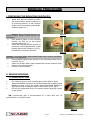
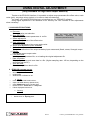
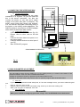
SCAIME S.A.S. - BP 501 - F-74105 ANNEMASSE Cedex
Tel. : +33 (0)4 50 87 78 64 - Fax : +33 (0)4 50 87 78 46
Web : www.scaime.com - E-mail : [email protected]
Smart strain sensor
epsimetal
®
USER MANUAL
The technical data are given in this handbook on a purely indicative basis and are not contractual. They
can be modified at any moment according to the technical requirements.
1/13
173700-C_NU-EPSIMETAL-E-1010_006076
synopsis
BONDING PROCEDURE ....................................................................................... 3
I. PREPARING THE MOUNTING SURFACES : ...................................................................... 3
II. SENSOR BONDING: ........................................................................................................... 3
1. Cyanoacrylat glue.:........................................................................................................................ 3
2. Epoxy Bi-Components Glue: ......................................................................................................... 4
III. REMOVING THE SENSOR: ............................................................................................... 4
RE-USING THE SENSOR ...................................................................................... 5
I.MOUNTING THE PLATES ON A SENSOR AND RE-USING IT: ........................................... 5
II. RE-USING A SENSOR ON BONDED PLATES: .................................................................. 5
USING DIGITAL ADJUSTMENT: .......................................................................... 6
1. Available functions : ...................................................................................................................... 6
3. Connecting the interface box......................................................................................................... 7
2. using parameter adjustment. ......................................................................................................... 7
DATA SHEET: HIGH LEVEL OUTPUT SENSORS ............................................. 10
I. TECHNICAL DATA : ................................................................................................................. 10
1. input :........................................................................................................................................... 10
2. output (standard version) : .......................................................................................................... 10
3. operational conditions : ............................................................................................................... 10
II. WIRING (VOLTAGE OUTPUT) : ................................................................................................ 11
III. WIRING (CURRENT LOOP) : ................................................................................................... 12
DATA SHEET : MV OUTPUT SENSORS ............................................................ 12
I. TECHNICAL DATA : ................................................................................................................. 12
1. input :........................................................................................................................................... 12
2. output : ........................................................................................................................................ 13
II. WIRING : .............................................................................................................................. 13
SIZE DRAWING ................................................................................................... 13
All accessories shown in this notice are available by SCAIME. Technical specifications : "FTAccessoires-Epsi" et FT-Epsimetal".
2/13
173700-C_NU-EPSIMETAL-E-1010_006076
BONDING PROCEDURE
I. PREPARING THE MOUNTING SURFACES :
o
Make sure that the surface on which
the sensor will be bonded (referred to
as “mounting surface”) is flat. Remove
all burrs and unevenness (paint drops,
soldering drops etc...).
Caution: Never bond the sensor to a
painted surface. Always scrape the paint off
beforehand.
o
Rub abrasive paper on the mounting
surface, as well as on the sensor
mounting plates (fig. 1).
o
Clean the mounting surface as well as
the sensor mounting plates with a cloth
soaked with solvent (acetone). (fig. 2).
Rub always in the same direction.
Figure 1.
Figure 2.
Caution: If mounting plates have already been used, remove remaining
glue tracks, then degrease.
o
Draw position marks for the sensor on the mounting surface using
a scriber. (fig. 3).
o
Clean this surface with a cloth soaked with solvent (acetone) Rub
always in the same direction.
o
Let dry for some minutes.
Figure 3.
II. SENSOR BONDING:
1. CYANOACRYLAT GLUE.:
o
o
o
Put a drop of glue on each mounting plate of the Sensor (fig 4).
Apply immediately the sensor on the mounting surface, paying close
attention to align it along the marks drawn beforehand. Maintain a
slight pressure on the sensor ends for one minute or two (fig 5).
Let the glue polymerize during 10 minutes, before applying a strain
on the sensor.
Figure 4.
NB: Cyanoacrylat glue is recommended for a short term use, its
good behaviour is limited in time.
Figure 5.
3/13
173700-C_NU-EPSIMETAL-E-1010_006076
2. EPOXY BI-COMPONENTS GLUE:
Drop the adhesive and hardener in a
cupel, and then mix them using a
spatula, for small quantities (fig 6).
Preparing larger quantities, it is
recommended to use the manual gun
with a mixing tube.
Spread out à fine layer of adhesive on
each mounting plate. (fig 7)
Apply the sensor on the mounting
surface, paying close attention to align it
along the marks drawn beforehand.
Hold in place the sensor with adhesive
tape on each end while the glue is
polymerizing. (fig 8)
Let the glue polymerize during 3 hours
at ambient temperature (20°) or 30
minutes at 80°c before removing the
tape. Wait for 24 hours before
performing a measurement.
o
o
o
o
o
Figure 6.
Figure 7.
NB : Epoxy glue is recommended for
long term use.
Figure 8.
III. REMOVING THE SENSOR:
o
Using a torque wrench, or a 2mm
hexagonal wrench, release the 2
screws at one end of the sensor. Then
the screws at the other end .( fig 9)
o
Remove the sensor. Both mounting
plates remain bonded on the mounting
surface.
o
To release the plates, position a small
chisel against the side of the plate,
then with a hammer, apply a small but
firm stroke on the plate.
Figure 9.
TIP: Holding in place the mounting
plates with a small piece of adhesive tape can
avoid losing them while releasing. (fig 10)
Figure 10.
Caution : Use only wrench in good condition; a damaged screw prevents from removing
the sensor, and can result in a severe damage to the sensor. Change screws as soon as the
first sign of tear and wear is noticed.
4/13
173700-C_NU-EPSIMETAL-E-1010_006076
RE-USING THE SENSOR
I.MOUNTING THE PLATES ON A SENSOR AND RE-USING IT:
o
If mounting plates have already been used, remove the
glue marks using a cutter and abrasive paper. (fig 11-12).
Set up the 1st plate with a slight tightening of each screw,
using the hexagonal end of the torque wrench or a 2mm
hexagonal spanner. (fig 13)
o
Then proceed the same way with the 2nd one.
o
Align the marks on sensor and plates.
o
Apply the sensor on a plane surface or in the positioning
gauge.
o
Using a torque wrench, tighten progressively and
successively each screw of a mounting plate, up to 1Nm
torque. (fig 14)
o
Figure 11.
Then proceed the same way with the 2nd one.
o
Rub the sensor on abrasive paper,
upon a flat surface to avoid
irregular wear.
o
Clean the mounting surface as well
as the sensor mounting plates with a
cloth soaked with solvent (acetone).
(fig. 2).
Figure 12.
The sensor is ready for use
CAUTION: tightening at a wrong
torque may result in an inacurate
measurement and 0 shift (if < 1 Nm)
or may damage the screws (> 1 Nm)
Figure 13.
Figure 14.
II. RE-USING A SENSOR ON BONDED PLATES:
Set up the sensor on his plates with a
slight tightening of each screw. Tighten
successively each screw in X. (fig 15).
Then tighten successively in the same
way each screw at 1 Nm, using the torque
wrench.
The same procedure may be used to
fasten directly the sensor in M2.5 tapped
holes. In this case, intercalate a 1.5 mm thick
brace between the sensor and the mounting
surface.
1
4
3
2
Figure 15.
5/13
173700-C_NU-EPSIMETAL-E-1010_006076
USING DIGITAL ADJUSTMENT:
(Only available for high level output sensors)
Thanks to the EPSILOG interface, it is possible to adjust some parameters like offset value, scale
value (gain), set points values (option), or to save or load new data files.
You need: a PC with RS 232 serial port, an interface box, an “EPSILOG” software.
Using digital adjustment is not essential for an ordinary use. But It allows on site adjustments
when necessary.
1. AVAILABLE FUNCTIONS :
a. Port com.
Communication port selection.
NB : The menus may show some
b. Save EEPROM.
differences,
depending
on
the
Save sensor adjustment parameters in .txt file.
activated optional functions.
c. Offset adjustment.
Automatic adjustment of the offset value.
d. Gain adjustment.
Automatic adjustment of the output scale value.
e. Alarm level adjustment (soon available).
f. Calibration.
Two points calibration of the output scale/any input measurand (Strain, stress, Strength, torque
g. Display.
Display the current output value.
h. Load EEPROM.
Loading a new adjustment file, or re-loading the original adjustment file.
i. Data acquisition.
Display signal curve and save data in a file. (Higher sampling rate= 100 ms, depending on the
serial port and the PC).
j. Save last data.
Save last acquisition data in a file.
2. EPSILOG program set up.
o
o
o
a. Minimum requirements
850 MHz processor
64 Mo RAM
Windows 98 or NT2000 or XP.
o
o
o
o
o
b. Set up
Insert EPSILOG CD ROM in driver.
Open CD ROM directory (double click)
Open EPSILOG directory (double click)
Double click on “install.exe” or “setup.exe”
Follow displayed instructions.
c.
o
o
Running
Start menu> Programs> EPSILOG directory
Double click on “Epsilog.exe”.
6/13
173700-C_NU-EPSIMETAL-E-1010_006076
BOITIER
INTERFACE
INTERFACE
BOX
3. CONNECTING THE INTERFACE BOX
d. General information
The connection between the two green
connectors is a “by-pass”. So you can insert the
box in the sensor connection. You also can
connect the sensor on one side and a power
supply on the other side (also a voltmeter). The
power supply feeds both sensor and interface.
You can use the unplugable connecting block or
the socket, or the mating socket adaptation. The
SUB D9 socket is connected to a RS232 adapter
which allows bi-directional data transfer.
e. Connecting the box.
o
Connect one side to the sensor (fig 16).
Please, refer to colour code on the last
page.
o
Connect the other side to the panel, or to
the power supply.
o
Connect SUB D9 socket to a serial port of
your PC.
o
Start “EPSILOG” program.
SEUIL 2
6
SEUIL 1
5
COM
SIGNAL
MASSE
+ALIM
Extensomètre
4
Epsimetal
3
2
1
INTERFACE
RS232
6 Set point 2
5 Set point 1
4 Digital I/O
3 + signal
2-Ground
1 Power supply
INTERFACE DE PROGRAMMATION
PROGRAMMING INTERFACE
Epsilog
Fig 16
1
2
3
4
5
6
2. USING PARAMETER ADJUSTMENT.
You can select a menu line by clicking on it or by clicking arrow up or down at the bottom of the
EPSILOG window. Then click “OK” to activate the function.
Clicking on OK starts a function or gets back to the menu when it's over.
Clicking on “Exit” gets back to the previous menu or quits the program when in the main menu.
a. Port com.
If your PC is equipped with several serial ports, or if an error message occurs, you have to select the good
one.
o
o
o
Click on “port com”, then on OK.
Select the port on which you are connected, using arrows up or down then clicking “OK”.
When “port com open” is displayed, click “OK”.
b. Save EEPROM
Be careful:
When you are about to change any parameter, always save the EEPROM content beforehand.
7/13
173700-C_NU-EPSIMETAL-E-1010_006076
o
o
o
Select “save EEPROM”, then OK.
The program reads automatically parameters in the strain sensor memory.
Choose filename and directory when asked.
Once this operation is done, you can modify the sensor memory.
Be careful:
Filename is your only reference for file identification. Choose it carefully; it must contain at least:
o Sensor serial number
o Calibration identification
o date
o
o
o
o
o
c. Offset adjustment
Select “offset adjustment”, then OK.
Enter final value (Volt) when asked.
Offset adjustment is done automatically.
The new value is displayed when the operation is over.
Select OK to get back to the menu.
Caution: be sure that the sensor is at its 0 position and that no strain occurs while operating
adjustment.
d. Gain adjustment
This operation is a modification of the internal electrical gain of the sensor, without calibration.
o
o
o
Select “gain adjustment”, then OK.
Enter the current output scale (volt) value corresponding to a given input span (µstrain, Strength….) when
asked, then “OK”.
Enter the output span you want to get (volt) corresponding to the same input span, then OK.
Caution: after this operation you must re-adjust offset when the sensor is back to its 0 position.
e. Calibration
This operation is a two point calibration of the output scale of the sensor. The sensor must be properly installed and
ready to use. It needs application of two different loadings on the feature you want to calibrate (one of them could
be 0).
o
o
o
o
o
o
o
o
Select “calibration”, then “OK”.
When “enter minimum tension value” is displayed, enter the output value (volt) you want for the lower value
of your input span, using the arrows up or down, and then “OK”.
When “enter maximum tension value” is displayed, enter the output value (volt) you want for the upper
value of your input span, using the arrows up or down, and then “OK”.
When “apply the 1st load” is displayed, apply the load corresponding to your 1st calibration point. (This load
can be 0)
Then enter the % of full scale corresponding to this load and then “OK”.
When “apply the 2nd load” is displayed, apply the load corresponding to your 2nd calibration point. (This
load must be > 1st load).
Then enter the % of full scale corresponding to this load and then “OK”.
Remove the load; the strain sensor is adjusted.
Tip:
You can improve the results, if you let the sensor work once or twice between max load and
0 before performing a calibration.
Tip:
Do not enter “0V” as lower output value. This is a saturation value.
8/13
173700-C_NU-EPSIMETAL-E-1010_006076
For example :
o Suppose you want to calibrate a strain sensor bonded on a beam, 5V at sensor’s output
corresponding to 10 kg input span, with an offset value of 0.5V.
o You have a 8 kg reference load.
o “enter minimum tension value”: enter “0.5”
o “enter maximum tension value”: enter “5.5”
o “apply 1st load”: let the beam free of load.
o “…”:enter “0%”, and then OK.
o “apply 2nd load” :Apply the 8 kg load on the beam.
o “…”:enter “80%”, and then “OK”.
o Remove the load.
o Your sensor must display 0.500 V.
f. Set points adjustment
(Soon available)
g. Loading file in EEPROM
Be careful:
When you are about to change any
parameter, always save the EEPROM content
You can get back to a previous
adjustment.
o
o
o
Select “loading file in EEPROM”, then
OK.
Select the file you want to load in the
strain sensor memory.
Select OK.
h. Data acquisition.
You can display sensor signal as a curve. You can also save data
in a text file or in an excel file.
o
o
o
o
o
o
o
o
o
o
o
Select “Data acquisition”.
Select ”Sampling”
If necessary, enter the sampling period (not less than 125)
Select OK.
Select “File type”
Tick the file extension you want.
Select OK.
When ready, select “Go”
To stop acquisition, click on “OK”
When asked, click on “OK” if you want to save data.
To quit data acquisition program, select “exit”
i. Save last acquisition.
You can save the last data, if it was not done before quitting
acquisition.
Remarks :
In every menu, « Exit » returns to the preceding menu. “OK” carries out
the subroutine, or confirm the next step, or stops it when it is running.
In the main menu,, « Exit » quits the main routine.
9/13
173700-C_NU-EPSIMETAL-E-1010_006076
DATA SHEET: HIGH LEVEL OUTPUT SENSORS
The items with built-in strain gages conditioning system are only concerned
These data are not contractual and are only indicative.
I. TECHNICAL DATA :
1. INPUT :
Power input (*)
Mini :
+9V
Maxi :
+28V( !)
Insulation resistance :
2MΩ
! Caution: only for new versions manufactured after October 31st, 2007.
The former versions with “12” in designation are limited to 18V
The former versions with “24” in designation are limited between 15 and 24V
2. OUTPUT (STANDARD VERSION) :
Strain range:
Mechanical overload:
Resolution :
Output span
Free offset value:
Max electrical overload:
Min electrical overload:
Linearity :
Hysteresis :
+/-500 µm/m
+/- 1000 µm/m
0.1 µm/m
5 V (floating) for 1000 µm/m
3V
7V
-0.070 V
<0.8% EM
<0.2% EM
With 4-20 mA converter:
Output span
Free offset value:
Max electrical overload:
Min electrical overload:
10 mA (floating) for 1000 µm/m
12 mA
23 mA
2.55 mA
3. OPERATIONAL CONDITIONS :
Operational temperature :
Temperature compensation:
Compensated material:
-40°C to +85°C
-10°C to +50°C
steel.
10/13
173700-C_NU-EPSIMETAL-E-1010_006076
II. WIRING (VOLTAGE OUTPUT) :
Item exemple : 450475,450477, 450472, 450478.
Seuil 1
Set point 2
Seuil 2
+ signal
Digital I/O
Power supply
Ground
Relais + Diodes de
roue libre
Signal
Com
+ Alim
Relays with
protection
diode
Afficheur
ou
Enregistreur
EXTENSOMETRE
Set point 1
Masse
Display
4
5
3
8
6
2
7
Connector
pos.
Front view of connector pins position
(Réf numbers with connector only)
1
Colour / Cable model
Wiring
Red, black, white,
green,
(3)
Red
Black
White
Green (1)
1
+ Power supply
2
- Common
3
+ Signal
4
Digital I/O
5
Set point 1 (2)
6
Set point 2 (2)
(1) Insulate wire end when it is not connected
(2) Only on demand
(3) Only for ref 450488
(4) Only for obsolete versions still in service
11/13
Red, black, white,
green, yellow, blue
( 4)
Red
Black
White
Green (1)
Blue (1)
Yellow (1)
Brown, green, yellow,
white, pink, grey.
Brown
Green
Yellow
White (1)
Pink (1)
Grey (1)
173700-C_NU-EPSIMETAL-E-1010_006076
III. WIRING (CURRENT LOOP) :
Item examples : 450470, 450471
Boucle de courant / Current loop
1 + alim / power supply
2
- commun / GND
5
- commun / GND
6 + courant / current loop
Marron / Brown
Vert / Green
Rose / Pink
Gris / Grey
4 Liaison série / digital I/O
0-10V sortie / output
3
Blanc / white
Jaune / yellow
4
5
3
8
6
2
7
1
Sorties optionnelles / optional output
connecteur vu de face
connector front view
(option)
DATA SHEET : MV OUTPUT SENSORS
The items without strain gages conditioning are only concerned
These data are not contractual and are only indicative.
I. TECHNICAL DATA :
1. INPUT :
Strain gage sensor ; to be used with a strain gage conditioning system..
Power supply (DC)
Minimal :
+2V
Nominal :
+5V
Maximum :
+10V
Full bridge
Bridge impedance :
1000 Ω
12/13
173700-C_NU-EPSIMETAL-E-1010_006076
2. OUTPUT :
Strain range:
Mechanical overload:
Output span :
Linearity :
Hysteresis :
Offset value :
+/-500 µm/m
+/- 1000 µm/m
4 to 6 mV/V for 1000 µm/m
<0.8% EM
<0.5% EM
0 ± 1.5 mV/V
The offset value is only indicative. This value is depending upon the bonding conditions and the quality
of surfaces. There is no temperature compensation on the mV versions, and the scale is not adjusted.
Wiring (mV output)
(item 450491)
+ bridge excitation
- bridge excitation
+ signal
- signal
Type 1 cable
Brown
Green
Yellow
White
Type 2 cable
Red
Black
White
Green or Blue
CONVENTION
Consider a positive signal in extension and a negative signal in compression
SIZE DRAWING
13/13
173700-C_NU-EPSIMETAL-E-1010_006076
Photos non contractuelles. SCAIME se réserve le droit d’apporter toute modification sans préavis.
II. WIRING :