1
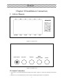
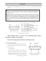
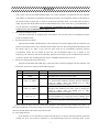
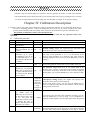
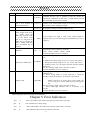
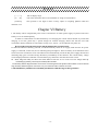
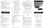
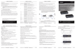
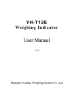
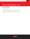
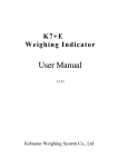
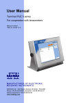
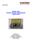
R-A12
Weighing
Indicator
User Manual
V1.01
Shanghai Yaohua Weighing System Co., Ltd
R-A12
Table of Contents
Chapter I. Technical Data...................................................................... - 2 Chapter II Installation Connection........................................................ - 3 I. Instrumentation Diagram................................................................. - 3 II. Sensor Connection ........................................................................... - 3 III. Serial Communication Interface and Large Screen......................... - 4 Chapter III Operation Instruction.......................................................... - 5 I. Startup ............................................................................................... - 5 II. Key Operation .................................................................................. - 5 III. Weighing Operation ........................................................................ - 6 Chapter IV Calibration Description ...................................................... - 8 Note: unplug the short-circuit ring after calibration. ............................ - 9 Chapter V Error Indication ................................................................... - 9 Chapter VI Battery.............................................................................. - 10 -
Dear users:
Please read the instruction manual carefully before using this indicator.
This indicator shall not be used for public trading!!!
-1-
R-A12
Chapter I.
1. Model
R-A12
Technical Data
2. Analog
Input signal range
-19mV~19mV
Conversion speed
More than 10 times/s
Nonlinearity
0.0015%
Gain drift
0.03%
Bridge voltage
DC 5V
Sensor connection
1-4 350Ω sensors
3. Indication
Indication range
-99999~999999 (decimal point is not considered)
Scale interval
1/2/5/10/20/50 optional
4. Serial communication interface
Signal
RS232 signal
Transmission distance
<20m
5. Operating environment
Power supply
AC220V; 50, 60Hz (-2%~+2%)
Operating temperature
-10 C
° ~40 °C
Storage and transport temperature
-25 C
° ~55 C
°
Relative humidity
≤85%RH
Fuse
6. Weight
500mA
Approx. 2 kg
-2-
R-A12
Chapter II Installation Connection
I. indicator Diagram
(Figure 2-1) Front cover
Power switch
AC power
Reserve
RS232
communication
Sensor
(Figure 2-2) Back cover
II. Sensor Connection
1. The sensor is connected through 9-pin plug socket (hole). Figure 2-3 shows the meaning of each lead
pin.
2. Please use 6-core shielded cable to ensure perfect metering performance of instrument.
-3-
R-A12
If there is only 4-core shielded cable on site, pins 1 & 2 and 6 & 7 can be shorted at the 9-pin sensor
connector.
▲!The connections of sensor and instrument must be reliable, and the shielded cable of
sensor must be reliably grounded. Connections lines shall not be plugged and pulled when the
instrument is in a Power-up State in order to prevent static electricity damaging the
instrument or sensor.
▲!Since both sensor and instrument is static-sensitive device, anti-static measures must be
practically taken in the use, and welding or other strong-electric operations on weighing
platform are strictly prohibited. In the thunderstorm season, reliable lightning protection
measures must be taken to prevent lightning damaging the senor and instrument and to
ensure the operator safety and the safe operation of weighing equipment and related
equipment.
(Figure 2-3) Sensor connection
Please short E- and S-, E+ and S+ if 4-core shielded cable is used, or
the indicator will not work properly.
III. Serial Communication Interface and Large Screen
Serial communication interface
1.
The data communication between R-A12 and upper
computer is realized through serial communication interface
in a continuous way.
2.
Connection mode
R-A12 communication interface uses 9-pin socket (pin).
laLead pin is defined as follows: pin 2 is for TXD (seri
ommunication data line) and pin 5 is for ground wire;c
hielded cable is recommended to be used as connections
.line. See Figure 2-4 for details
-4-
(Figure 2-4) Communication and
large screen connection
R-A12
3.
Interface parameter
①
Signal: RS232C
②
Baud rate: 600/1200/2400/4800/9600. See the chapter of calibration instruction for baud rate
setting methods.
Data format: = <Weight data (including decimal point)>, all data are in ASCII format.
③
Note: = data format header, ASCII code.
<Weight data (including decimal point)>: 6 digits (including decimal point) of weight data with
symbol, ASCII code.
The lower digits are in front, and the higher digits and symbol digits are in the rear. Negative symbol
bit is "-", and positive symbol is "0".
For example, if the weight shown in the indicator is -500.00kg, the serial output data will be "=
00.005-".
If the weight shown in the indicator is 500.00kg, the serial output data will be "= 00.0050".
Large screen
See Figure 2-4 for wiring details. Large screen signal is current loop signal of 20mA constant current and
is output in a serial way through binary code, with a baud rate of 600. Each frame has 11 data bits, including
one start bit (0), eight data bits (LSB in front), one flag bit, and one stop bit (1).
Chapter III Operation Instruction
I. Startup
The instrument gets into self-check process after the power supply is connected. If the weight on platform
is within the startup zero setting range, automatic zero setting will working, than the weighing state is enabled.
If the weight on platform exceeds the zero setting range, the indicator will give tips and indicate the said
weight.
II. Key Operation
In the calibration and parameter setting state, some keys will perform the following functions:
1. ZERO key performs the "plus 1" function. After the ZERO key is pressed, the figure displayed in the last
bit will be "plus 1", automatic zero setting will be made after it is added to 9.'
2. TARE key performs the "shift" function. After the TARE key is pressed, the figure shown in the last bit
will move to the left for one bit, and the last bit will be supplemented with 0. If the 6-bit indication or
effective bit is exceeded after the movement of some one figure to the left, the figure will be discarded.
3. HOLD key performs "input" function. Press the HOLD key to put the set data into indicator.
4. CLEAR key performs "exit" function. Press the CLEAR key to exit calibration or state setting.
-5-
R-A12
III. Weighing Operation
1. ZERO:
Press ZERO key to enable the data within zero setting range of instrument to return to zero. Zero
setting can be performed only after the STABLE indication lights.
2. TARE:
When the displayed weight in weighing state is positive and the STABLE light will on, press the
TARE key to deduct the indicated weight (as the tare). In this case, the instrument will show a net weight
of "0" and the NET WEIGHT lights will on. Press the TARE key again when gross weight is 0, the
instrument will clear the tare value.
3. Magnification:
Press the FUNCTION key when tare value is 0 in weighing state, the weighing accuracy will be 10
times larger, and press the FUNCTION key again to return normal (magnification of net weight cannot
be shown, and the data cannot be enlarged beyond the range of display).
4. HOLD, average value:
Press HOLD key in weighing state, the PEAK VALUE light will on which indicates peak value. If
the current weight is less than 5% of full capacity, it will return normal; press the HOLD key again, the
AVERAGE VALUE light will on. In this case, when it becomes stable relatively(the indicator will make
automatic determination on whether it is stable), the indicator will calculate the average value and show
it after flashing. The average value will be cancelled when the current weight returns to "0", and the next
average value can then be measured; press the HOLD key again, the instrument will return to normal
weighing mode. In this case, the HOLD key can be pressed to convert the mode.
5. Manual accumulation of measured value:
Press the "ACCUMULATION" key when the measured value is larger or equal to 20 divisions and
the data is stable in the normal weighing state, the indicator will perform "manual accumulation"
function. In this case, the indicator will indicate the total accumulation data (in two steps): [total = ]
(indicating that the content shown below is the amount of accumulation data) will show the
accumulation data [******] in about 1 second. The times of accumulation will be then indicated (in two
steps): [n = ] (indicating that the times is shown below) will show the times of accumulation [ ***] in
about 1 second. The ACCUMULATION indicating light is then on.
Note: the maximum times of accumulation is 9999 (when accumulation result is ensured to be
≤999999); The accumulation results will be held before they are cleared and the data will not be lost
after power-off. When the ACCUMULATION key is pressed, if the net weight is less than 20
divisions, only the accumulation value will be indicated, and the accumulation of weight and times
will not be made.
6. Automatic accumulation of measured value:
Press the FUNCTION and ACCUMULATION keys at the same time in normal weighing state and
not the peak value holding and average value state, the indicator will enter the automatic accumulation
-6-
R-A12
state. In this case, the ACCUMULATION light is on. In the automatic accumulation state, the indicator
will perform an automatic accumulation and indicate the times of accumulation and the results whenever
the measured data is larger than or equal to 20 divisions and after about 1-2 seconds after the data is
stable. Re-press the FUNCTION and ACCUMULATION keys at the same time or press HOLD key to
exit the automatic accumulation. Note: automatic accumulation state will be saved when the power
is off; however, the accumulation data will be saved.
7. Clear the accumulation result:
Press the CLEAR key in weighing state, the indicator will clear the times of accumulation and the
overall accumulation data.
8. Switching between kg and lb:
Press the FUNCTION and HOLD keys at the same time in normal weighing state, the indicator will
perform switching between units; when the measurement unit is lb, the last digit behind decimal point of
the shown data is on. Note: if one unit has been used for an accumulation operation and the
accumulation results are not cleared (in this case, the accumulation light is on or flashes at low
frequency), the indicator will forbid switching between units which can be conducted only after the
results are cleared. The switching between units is forbidden when the tare is not "0".
9. Preset tare and upper & lower limits alarm:
Press the FUNCTION and TARE keys at the same time in normal weighing state, the indicator will
perform the "preset tare" function in the following steps:
Step
1
2
3
Operation
Press FUNCTION +
TARE
Input the preset tare
value, e.g. “6000”
Display
[******]
[P00000]
Description
Weighing indication status
[
Press ZERO key for six times to set the lowest digit to
"6", and press the TARE key for three times to change the
value to "6000". Press the HOLD key to make
confirmation and move to Step 4.
Press ZERO key for six times to set the lowest digit to,
and press the TARE key for three times to change the
value to "3000". Press the HOLD key to make
confirmation and move to Step 5.
Press the ZERO key to set the lowest digit to "0", and
press the TARE key to change the value to "00000". Press
the HOLD key to make confirmation and move to Step 6.
Go back to weighing mode., displaying net weight after
tare.
6000]
4
Upper limit alarm
value, e.g. “3000”
[H 00000]
5
Lower limit alarm
value, e.g. “0”
[L 00000]
6
[******]
Guide the user to enter preset tare value.
[Note]: cancel the upper and lower limit alarm operation when both the upper and the lower limit is 0;
press the CLEAR key to cancel the setting at any time while setting, the current setting data will not be saved;
however, the data before the current step will be saved.
10. Auto-sleep function
If the indicator is in a continuously steady state and there is no any key and measurement operations
(setting for 30 or 60 seconds as optional), it will automatically enter into auto-sleep state. In this
-7-
R-A12
condition, only last decimal light is on. If there is any key operation in mode 1 or mode 2, the indicator
will automatically exit the sleep state and get into normal work state; only by pressing the keys in mode
3 or mode 4 can the instrument exit the sleep state. See the table in Chapter IV for specific settings.
Chapter IV Calibration Description
I.
Properly connect the signal source and power supply to preheat the indicator for 15-30 minutes when there is
no load on weighing platform. connect the calibration short-circuit ring in normal weighing state while
pressing the FUNCTION and CLEAR key at the same time, the indicator will get into calibration state.
The position of calibration switch on circuit board is JP7.
[Note]: Please refer to the second section of the third chapter about the key operation before next
operation.
II. Calibration procedure
Step
1
2
3
4
Operation
Press
FUNCTION
+
CLEAR keys
Input the password and
press the HOLD key to
confirm
Input a new division
parameter, e.g. “1”: press
the ZERO key once to set
the indicated data to “1”
and press the HOLD key
to confirm
5
6
Input a new number of
decimal, e.g. "3": press the
ZERO key for three times
to set the indicated data as
"3" and press the HOLD
key to confirm.
7
8
Input a new full capacity,
e.g. "6000": press the
ZERO key for six times to
set the lowest (last) digit
as "6", and press the
TARE key for three times
to change the data to
"6000", and then press the
HOLD key to confirm.
Display
[******]
Weighing mode
[P ***]
The password of calibration. The password is 111.
[d
*]
Division setting: display the original division parameter and
guide the user to enter a new division parameter.
[d
1]
The range of this parameter is 1, 2, 5, 10, 20 and 50; if the
division value parameter to be entered is the same with the
currently displayed value, you can press the HOLD key to move
to Step 4.
[dP
*]
Decimal number setting: display the original number of
decimal and guide the user to enter a new number of decimal
3]
The parameter ranges from 0 to 3; "0" means there is no
decimal, and 1-3 means 1-3 decimal; if the number of decimal
to be entered is the same with that of the currently displayed
decimal digit, you can press HOLD key to move directly to Step
6.
[F*****]
(F is not
displayed
when the
measuring
range
occupies 6
digits)
Full-capacity setting: display the original full capacity and
guide the user to input a new full capacity.
(If the value 3190 is input, you can press the HOLD key to
return to weighing mode. Restart the indicator and the factory
setting will be recovered)
[
6000]
If no need of zero and full value calibration currently, you can
press the HOLD key to move to Step 13. If re-calibration is
required, the full capacity must be input again before Step 8 and
9.
[noloAd]
Zero calibration: in this case, the indicator will check the zero
position automatically. If zero position has never been calibrated
the zero inner code will be displayed, or the Step 9 will be
[dP
9
Description
-8-
R-A12
10
[ LoAd ]
11
After the weight is loaded,
wait a few seconds to
press the HOLD key
12
13
[******]
[******]
input the value of current
actual weight on the scale,
e.g. "3000": press the
ZERO key for three times
to set the lowest (last)
digit to "3", and press the
TARE key to change the
data to "3000", and then
press the HOLD key to
confirm.
[
3000]
14
Baud rate
[bt
*]
15
moved to rapidly
Full-capacity calibration: indicator zero position has been
confirmed and the user is guided to load the weight for
full-capacity calibration. In this case, a weight which is more
than 1/2 of full capacity can be loaded.
The indicator displays the current inner code for the weight
loaded to scale. If the loaded weight is too small, you shall go
back to Step 9 for re-loading of weight.
After the data is stable, the indicator will calculate and display
the weight according to original calibration rate.
If the weight to be input is same as the actual weight on
weighing scale, you can directly press the HOLD key to move
to Step 13.
Baud rate setting: display the original baud rate of indicator,
and guide the user to input new baud rate.
0:600 1:1200 2:2400 3:4800 4:9600
Press the HOLD key to move to Step 14.
A - Zero tracking range (0-5) means 0, 0.5e, 1e, 1.5e, 2e and
2.5e.
Operation in ZERO zone
[n ABCD]
16
Display mode
16
[LEd AB]
[******]
B - Manual zero setting range (0-5) 0, 2, 4, 10, 20, 100 (100%)
C - Startup zero setting range (0-5) 0, 2, 4, 10, 20, 100 (100%)
D - Stability scope (1-5). the larger value the stronger stability
of indicator.
The way to change input value is the same as above.
Press the HOLD key to move to Step 15.
A - Display the brightness. Larger values indicate higher
brightness (0-5)
B - Power saving mode. 0: saving mode off; 1: about 30
seconds; 2: about 60 seconds 3: 30 seconds 4: 60 seconds
Modes 3 and 4 are of strong power saving mode, you
can exit the power saving mode only by pressing the
key
The way to change input value is the same as above.
C - Power status light refreshes time. 0: 5 seconds; 1: 30
seconds.
Press the HOLD key to move to Step 16.
Calibration is complete. Return to weighing mode.
Note: unplug the short-circuit ring after calibration.
Chapter V Error Indication
[Err
1]
Inner code loaded is too small or the capacity of load cell is too large
[Err
2]
Out of manual zero setting range
[Err
5]
Inner code loaded is too small or the capacity of load cell is too large
[Err
7]
The calibration short-circuit ring did not connected
-9-
R-A12
[----------]
Out of display range
[A
Out of the maximum times of accumulation or weigh of accumulation
oL]
[HHHHHH]
Zero position is too high or there is heavy object on weighing platform when the
indicator is on
Chapter VI Battery
I. The battery will be charged after power cord is connected to AC 220V power supply. So please remove the
battery if it is not used frequently.
In order to avoid internal over-heat and battery over-charging, the current will be limited. If you feel that
charging is too slow, please buy a special charger for external charging. Please note that the wire ends
connected to battery shall not be connected inversely (red +, black -), or the indicator may burn out.
Be sure to fully charge the battery before using the built-in battery for the first time!
II. When the indicator is battery-powered, it will automatically switch to AC supply mode once the AC power
supply is connected; in this case, the AC indicating lamp will light on. There are battery level indications at the
lower left corner of indicator screen. The indicator will automatically cut off the DC power supply after the last
indicating lamp goes out. Please charge the battery immediately in this situation. The current battery voltage
can be displayed when the indicator is started. Please pay attention to this data from time to time.
III. Please charge the battery for about 10-16 hours before its first use so as to avoid a too low voltage caused by
self-discharging of battery which may be mistakenly taken as failure.
IV. The battery shall be charged for about 10-16 hours at a time during the normal operation. If the indicator is not to be used for
long, the battery shall be charged for 10-16 hours every two months in order to extend its service life.
V. The built-in battery of indicator is a consumable part that is not within the range of "three guarantees".
- 10 -