1
Embedded Automation, Inc.
Suite #104, 7485 – 130th Street
Surrey, BC
V3W 1H8
Phone: (604) 596-4999
Fax: (604) 596-4933
www.EmbeddedAutomation.com
v2
(Home Edition)
User Manual
Digital Home Software
Page 1
mControl v2 (Home Edition) User Manual
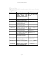
Revisions
Date
Revision Description
February 14, 2008
Amended to include information on mControl v2.1 Release Candidate 1 (RC1)
April 4, 2008
Amended to include information on mControl v2.1 Formal Release (RCGOLD)
May 15, 2008
Amended to include information on mControl v2.1 Formal Release (RCGOLD2)
Page 2
mControl v2 (Home Edition) User Manual
Table of Contents
TABLE OF CONTENTS ........................................................................................................................................................3
INTRODUCTION..................................................................................................................................................................10
SYSTEM REQUIREMENTS .............................................................................................................................................11
SOFTWARE REQUIREMENTS ...................................................................................................................................................11
mControl (Automation) Service...........................................................................................................................................11
mControl (User Interface) Clients.......................................................................................................................................11
MEDIA CENTER INTERFACE.....................................................................................................................................................11
Screen Settings......................................................................................................................................................................11
Supported Media Center Extenders.....................................................................................................................................11
SUPPORTED HARDWARE.........................................................................................................................................................12
Security Cameras..................................................................................................................................................................12
Security Systems....................................................................................................................................................................13
HVAC Systems......................................................................................................................................................................14
IR Support .............................................................................................................................................................................15
Irrigation Controllers...........................................................................................................................................................16
Voice Recognition Support...................................................................................................................................................16
INSTEON Protocol...............................................................................................................................................................17
INSTEON Adapters................................................................................................................................................................................17
INSTEON Devices .................................................................................................................................................................................20
Hybrid INSTEON and X10 Environments ...........................................................................................................................................21
X10 to INSTEON Address Translations............................................................................................................................................21
Adapter Considerations for Hybrid INSTEON and X10 Environments..........................................................................................21
Advanced INSTEON Functionality.......................................................................................................................................................22
Link Databases...................................................................................................................................................................................22
Smarthome HouseLinc Software.......................................................................................................................................................23
Links and Device Status.....................................................................................................................................................................23
Macro Triggering and Real-time Status Changes from SwitchLinc Paddle Presses .....................................................................24
Setting Preset On and Ramp Rates.........................................................................................................................................................24
Z-Wave Protocol...................................................................................................................................................................25
Z-Wave Adapters....................................................................................................................................................................................25
Real-time Information Display..........................................................................................................................................................26
Z-Wave Devices .....................................................................................................................................................................................27
Z-Wave Adapter Utility..........................................................................................................................................................................28
Connection Options ...........................................................................................................................................................................29
Controller Options.............................................................................................................................................................................30
Device Options...................................................................................................................................................................................31
mControl Automation Service Options .............................................................................................................................................32
Z-Wave Adapter Information.............................................................................................................................................................32
Adding Z-Wave Devices to mControl...................................................................................................................................................33
Removing Z-Wave Devices from mControl .........................................................................................................................................34
Rako Protocol .......................................................................................................................................................................35
Rako Adapters.........................................................................................................................................................................................35
Rako Devices ..........................................................................................................................................................................................35
X10 Protocol.........................................................................................................................................................................36
X10 Adapters ..........................................................................................................................................................................................36
PowerLinc 1132Cx Adapter..............................................................................................................................................................37
PowerLinc 2414x/2814x Adapter......................................................................................................................................................37
CM11A X10 Adapter .........................................................................................................................................................................38
CM17A X10 Adapter .........................................................................................................................................................................38
CM15A/CM19A X10 Adapter ...........................................................................................................................................................39
Page 3
mControl v2 (Home Edition) User Manual
W800RF32A X10 Adapter.................................................................................................................................................................39
Alternate Adapter Resolution ............................................................................................................................................................40
X10 Devices............................................................................................................................................................................................40
Leviton X10 Devices ..............................................................................................................................................................................41
Limitations and Recommendations......................................................................................................................................41
MCONTROL INSTALLATION........................................................................................................................................42
STEP 1 - INSTALL MCONTROL SOFTWARE.............................................................................................................................42
mControl Trial Version ........................................................................................................................................................42
Upgrading mControl............................................................................................................................................................43
Uninstalling mControl from Windows XP Systems.............................................................................................................................43
Uninstalling mControl from Windows Vista Systems..........................................................................................................................44
Uninstalling mControl from Windows Home Server Systems ............................................................................................................44
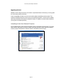
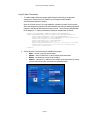
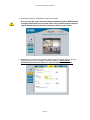
Downloading the Latest Version of mControl ....................................................................................................................45
Installing mControl...............................................................................................................................................................47
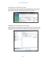
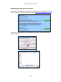
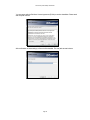
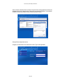
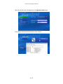
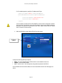
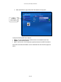
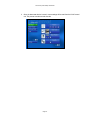
Installing mControl on Windows XP and Windows Vista Systems....................................................................................................47
Installing mControl on Windows Home Server Systems .....................................................................................................................50
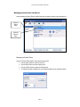
Copy the mControl Installer to Windows Home Server...................................................................................................................50
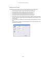
Use the Windows Home Server Add-in Manager to Install mControl............................................................................................51
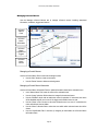
Restricting User Access to mControl ................................................................................................................................................52
mControl Installation Information..........................................................................................................................................................53
Default Install Locations....................................................................................................................................................................53
Installed mControl Components........................................................................................................................................................53
Installed 3rd Party Software Components........................................................................................................................................54
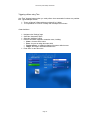
STEP 2 - START MCONTROL SOFTWARE ...............................................................................................................................55
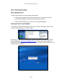
Before Starting mControl.....................................................................................................................................................55
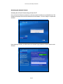
Starting mControl for Internet Explorer..............................................................................................................................55
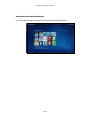
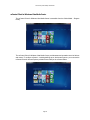
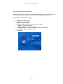
Starting mControl within Media Center..............................................................................................................................56
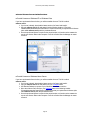
STEP 3 – ACTIVATING MCONTROL .........................................................................................................................................57
mControl License from a Purchased CD............................................................................................................................57
mControl License from an Online Purchase.......................................................................................................................58
mControl License on Windows XP or Windows Vista ........................................................................................................................58
mControl License on Windows Home Server.......................................................................................................................................58
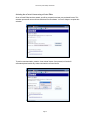
Activating the mControl License..........................................................................................................................................59
Activating the mControl License using mControl for IE......................................................................................................................59
Activating the mControl License using mControl Editor .....................................................................................................................61
Using Manual Activation .......................................................................................................................................................................62
Moving mControl to a New Computer ................................................................................................................................63
Using mControl with a Dial-up Internet Connection .........................................................................................................63
USING MCONTROL SOFTWARE................................................................................................................................64
MCONTROL COMPONENTS ......................................................................................................................................................64
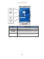
mControl (Automation) Service...........................................................................................................................................64
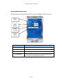
mControl (User Interface) Clients.......................................................................................................................................65
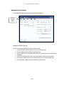
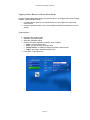
mControl and Internet Explorer .............................................................................................................................................................66
Touch Screen Operation .........................................................................................................................................................................68
Media Center Extenders .........................................................................................................................................................................68
Interaction Between the mControl (Automation) Service and mControl Clients..............................................................69
Ethernet Ports Used by mControl...........................................................................................................................................................69
mControl and Internet Information Services (IIS) ..............................................................................................................70
MCONTROL SERVICE MANAGER ............................................................................................................................................73
mControl (Automation) Service Control Functions............................................................................................................73
mControl (Automation) Service Configuration...................................................................................................................74
mControl (Automation) Service Status................................................................................................................................74
Managing mControl Driver Collections .............................................................................................................................74
mControl (Automation) Service Options.............................................................................................................................75
MCONTROL EDITOR .................................................................................................................................................................76
Page 4
mControl v2 (Home Edition) User Manual
mControl Editor Connection Control..................................................................................................................................76
mControl Editor Configuration ...........................................................................................................................................77
mControl Editor Connection Status.....................................................................................................................................77
Managing mControl Zones and Devices.............................................................................................................................78
Managing mControl Zones.....................................................................................................................................................................78
Managing mControl Devices .................................................................................................................................................................79
Managing mControl Macros ...............................................................................................................................................80
Managing mControl Macros ..................................................................................................................................................................80
Managing mControl Macro Information ...............................................................................................................................................80
Managing mControl Macro Conditions and Triggers...........................................................................................................................81
Managing mControl Macro Actions......................................................................................................................................................81
Managing mControl IR and External Trigger Commands ................................................................................................82
Managing mControl Commands............................................................................................................................................................82
Managing mControl Settings ...............................................................................................................................................83
Managing mControl Settings .................................................................................................................................................................83
Managing mControl Version and License Information......................................................................................................84
Manage mControl Version and License Information ...........................................................................................................................84
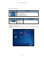
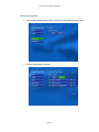
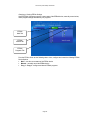
MCONTROL CLIENT FOR WINDOWS VISTA MEDIA CENTER.................................................................................................85
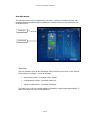
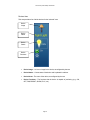
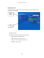
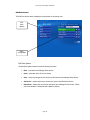
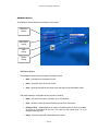
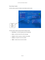
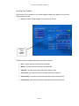
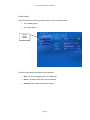
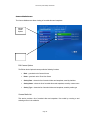
Zone View Screen .................................................................................................................................................................86
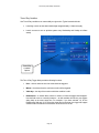
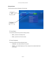
Zones Area ..............................................................................................................................................................................................86
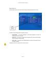
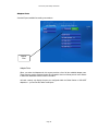
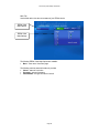
Devices Area ...........................................................................................................................................................................................87
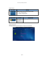
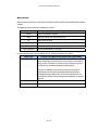
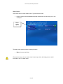
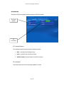
Switches, Lamp and Appliance Devices............................................................................................................................................88
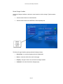
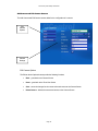
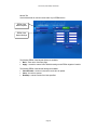
HVAC (Thermostat) Devices.............................................................................................................................................................89
HVAC (Thermostat) Detail Screen....................................................................................................................................................89
Irrigation Devices ..............................................................................................................................................................................90
Irrigation Detail Screen.....................................................................................................................................................................90
Security System Devices.....................................................................................................................................................................91
Security System Detail Screen...........................................................................................................................................................91
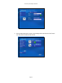
Camera Devices.................................................................................................................................................................................92
Camera Detail Screen........................................................................................................................................................................92
Macro Devices ...................................................................................................................................................................................93
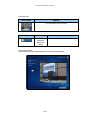
MCONTROL CLIENT FOR INTERNET EXPLORER AND MEDIA CENTER 2005.......................................................................94
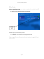
Zone View Screen .................................................................................................................................................................94
Zones Area ..............................................................................................................................................................................................94
Access to mControl Settings ..................................................................................................................................................................94
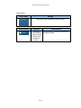
Devices Area ...........................................................................................................................................................................................95
Real-time Display of Device Status...................................................................................................................................................96
Switches, Lamp and Appliance Devices............................................................................................................................................97
HVAC (Thermometer) Devices .........................................................................................................................................................98
Irrigation Devices ..............................................................................................................................................................................98
Security System Devices.....................................................................................................................................................................99
Camera Devices.................................................................................................................................................................................99
Macro Devices .................................................................................................................................................................................100
Settings Screen....................................................................................................................................................................101
Settings Options ....................................................................................................................................................................................101
Configuration Options ..........................................................................................................................................................................101
mControl Information...........................................................................................................................................................................102
Configuration Screen .........................................................................................................................................................103
Configuration Options ..........................................................................................................................................................................103
Configuration Settings (Main)..............................................................................................................................................................104
Configuration Settings (Location)........................................................................................................................................................105
Manage Zones Screen ........................................................................................................................................................106
Manage Zone Options ..........................................................................................................................................................................106
Zone Configuration...............................................................................................................................................................................107
Add Zone Screen.................................................................................................................................................................108
Add Zone Options.................................................................................................................................................................................108
Zone Name............................................................................................................................................................................................108
Edit Zone Screen.................................................................................................................................................................109
Edit Zone Options.................................................................................................................................................................................109
Page 5
mControl v2 (Home Edition) User Manual
Zone Configuration...............................................................................................................................................................................110
Edit Device Screen..............................................................................................................................................................111
Edit Device Options..............................................................................................................................................................................111
Device Configuration Menu.................................................................................................................................................................112
Device Settings (Main).........................................................................................................................................................................113
Device Settings - Adapters..............................................................................................................................................................114
Adding INSTEON Devices ..............................................................................................................................................................115
Adding Z-Wave Devices...................................................................................................................................................................116
Adding X10 Devices.........................................................................................................................................................................117
Adding Security System Devices......................................................................................................................................................118
Adding Thermostat Devices.............................................................................................................................................................118
Device Settings (Advanced).................................................................................................................................................................119
Advanced INSTEON Settings ..........................................................................................................................................................120
Advanced Z-Wave Settings ..............................................................................................................................................................120
Automation Screen..............................................................................................................................................................121
Automation Options..............................................................................................................................................................................121
Macro List .............................................................................................................................................................................................122
Add Macro Screen..............................................................................................................................................................123
Add Macro Options ..............................................................................................................................................................................123
Macro Details Screen.........................................................................................................................................................124
Macro Details Options..........................................................................................................................................................................124
Macro Triggers List ..............................................................................................................................................................................125
Macro Actions List ...............................................................................................................................................................................126
Edit Macro Screen.................................................................................................................................................................................127
Macro Triggers...................................................................................................................................................................128
Add Triggers Screen.............................................................................................................................................................................129
Edit Triggers Screen .............................................................................................................................................................................130
Device Change Condition.....................................................................................................................................................................131
Device Status Condition .......................................................................................................................................................................134
IR Event Condition ...............................................................................................................................................................................136
MCE Event Condition ..........................................................................................................................................................................137
Time Range Condition..........................................................................................................................................................................139
Recurring Timer Condition ..................................................................................................................................................................140
One Time Condition .............................................................................................................................................................................141
Time of Day Condition.........................................................................................................................................................................142
Sunrise/Sunset Conditions....................................................................................................................................................................143
Macro Actions.....................................................................................................................................................................145
Device Actions......................................................................................................................................................................................146
Delay Actions........................................................................................................................................................................................148
IR Actions..............................................................................................................................................................................................149
Macro Actions.......................................................................................................................................................................................150
Send Mail Actions.................................................................................................................................................................................151
Run Application Actions ......................................................................................................................................................................152
Camera Screen ...................................................................................................................................................................153
Automation Options..............................................................................................................................................................................153
Camera List ...........................................................................................................................................................................................153
Add Camera and Edit Camera Screens.............................................................................................................................154
Edit Camera Options.............................................................................................................................................................................154
Camera Settings ....................................................................................................................................................................................155
Camera Media Screen.......................................................................................................................................................156
Edit Camera Options.............................................................................................................................................................................156
Camera Media List................................................................................................................................................................................156
IR Control Screen ...............................................................................................................................................................157
IR Control Options................................................................................................................................................................................157
IR Control Configuration......................................................................................................................................................................157
Adapters Ports ....................................................................................................................................................................158
Adapter Ports.........................................................................................................................................................................................158
IR Commands .....................................................................................................................................................................159
IR Command Options...........................................................................................................................................................................159
Page 6
mControl v2 (Home Edition) User Manual
IR Commands .......................................................................................................................................................................................159
MCONTROL CLIENT FOR WINDOWS MOBILE .......................................................................................................................160
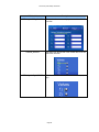
mControl Mobile Zone View..............................................................................................................................................161
mControl Mobile Thermostat View ...................................................................................................................................161
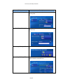
mControl Mobile Security View.........................................................................................................................................163
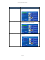
mControl Mobile Camera View.........................................................................................................................................164
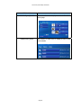
mControl Mobile Irrigation View......................................................................................................................................164
ADVANCED MCONTROL FUNCTIONALITY .............................................................................................................................165
Using Macros......................................................................................................................................................................165
Macro Basics.........................................................................................................................................................................................165
Summary of Macro Conditions............................................................................................................................................................166
Device-Based Macro Conditions ....................................................................................................................................................166
Time-Based Macro Conditions........................................................................................................................................................167
Other Macro Conditions..................................................................................................................................................................167
Summary of Macro Actions.................................................................................................................................................................168
Device-Based Macro Actions..........................................................................................................................................................168
Other Macro Actions .......................................................................................................................................................................169
Triggering a Macro Based on a Device Status Change.......................................................................................................................170
Create the Macro .............................................................................................................................................................................170
Add a Trigger to the Macro.............................................................................................................................................................171
Add Conditions to the Trigger.........................................................................................................................................................172
Add Actions to the Macro ................................................................................................................................................................173
Triggering Macros Using INSTEON SwitchLinc or KeypadLinc Buttons ...................................................................................174
Triggering a Macro using Time ...........................................................................................................................................................175
Create the Macro .............................................................................................................................................................................175
Add a Trigger to the Macro.............................................................................................................................................................176
Add Conditions to the Trigger.........................................................................................................................................................176
Add Actions to the Macro ................................................................................................................................................................178
Using the Recurring Timer with Macros.............................................................................................................................................179
Create the Macro to Utilize Recurring Timers...............................................................................................................................179
Add a Trigger to the Macro.............................................................................................................................................................180
Add Conditions to the Trigger.........................................................................................................................................................180
Add Actions to the Macro ................................................................................................................................................................181
Using MCE Events to Trigger Macros ................................................................................................................................................182
Install and configure the MCE Add-in Utility.................................................................................................................................182
Create the Macro to Utilize MCE Events .......................................................................................................................................184
Using External Programs within Macro Actions ................................................................................................................................188
Enable External Program Action Functionality.............................................................................................................................188
Enable Interactive Applications (GUI Apps)..................................................................................................................................188
Example External Application Action.............................................................................................................................................189
Using Security Systems.......................................................................................................................................................191
Supported Security Systems.................................................................................................................................................................191
Using Elk Security Systems .................................................................................................................................................................191
Using Digital System Control (DSC) PowerSeries Security Systems ...............................................................................................193
Using Honeywell ADEMCO VISTA Security Systems ....................................................................................................................195
Understanding Security Systems Status...............................................................................................................................................197
Changing Security Systems Settings....................................................................................................................................................198
Security View Screen Overview.......................................................................................................................................................198
Security View Main Tab...................................................................................................................................................................199
Security Zones Tab...........................................................................................................................................................................200
Triggering Macros using Security System Events ..............................................................................................................................201
Using Irrigation Controllers..............................................................................................................................................202
Irrigation Controllers.............................................................................................................................................................................202
EZ Rain V1 Irrigation Controllers........................................................................................................................................................202
Add an EZRain Irrigation Controller to mControl ........................................................................................................................202
Changing or Viewing EZRain Settings ...........................................................................................................................................205
Main Tab ..........................................................................................................................................................................................206
Manual Tab ......................................................................................................................................................................................207
Program Tab....................................................................................................................................................................................208
Page 7
mControl v2 (Home Edition) User Manual
Using Thermostats..............................................................................................................................................................209
Using HAI Thermostats........................................................................................................................................................................209
Using Proliphix Thermostats................................................................................................................................................................211
Using RCS Thermostats .......................................................................................................................................................................213
Using RCS TXB16 Thermostats ......................................................................................................................................................213
Using RCS TZ16 Thermostats.........................................................................................................................................................215
Understanding Thermostat Status ........................................................................................................................................................216
Changing Thermostat Settings .............................................................................................................................................................217
Adjusting HVAC Settings in Macros ..................................................................................................................................................218
Using Cameras ...................................................................................................................................................................219
Viewing Cameras on mControl Clients...............................................................................................................................................219
Using Axis Cameras .............................................................................................................................................................................221
Using Panasonic Cameras ....................................................................................................................................................................225
Using D-Link Cameras.........................................................................................................................................................................229
Adding a Custom Camera ....................................................................................................................................................................233
Using Advanced Camera Functionality from the Camera View page...............................................................................................235
Camera View Options......................................................................................................................................................................235
Pan-Tilt-Zoom Options....................................................................................................................................................................235
Using Camera Devices within Macros ................................................................................................................................................236
Triggering Macros based on Camera Motion Detection...............................................................................................................236
Recording Videos as a Macro Action .............................................................................................................................................240
Taking Snapshots as a Macro Action..............................................................................................................................................242
Viewing Recorded Videos and Snapshots within Windows Media Center.......................................................................................243
Using IR Commands ..........................................................................................................................................................245
Configuring Global Caché for Use with mControl .............................................................................................................................245
Configuring USB UIRT for Use with mControl.................................................................................................................................248
Entering and Testing IR Commands....................................................................................................................................................250
Adding IR Commands (using CCF Format)...................................................................................................................................250
Learning IR Commands...................................................................................................................................................................251
Testing IR Commands......................................................................................................................................................................252
Sending IR commands within mControl Macros Actions..................................................................................................................253
Using IR commands as mControl Macros Triggers............................................................................................................................254
IR Commands and Windows XP Media Center Edition 2005...........................................................................................................254
Adding Voice Control.........................................................................................................................................................255
Basic Voice Control Operation ............................................................................................................................................................255
Extending Voice Control......................................................................................................................................................................257
Configuring mControl Clients ...........................................................................................................................................258
Using mControl from a remote PC using Internet Explorer ...............................................................................................................258
Adding mControl to a remote Windows XP Media Center Edition PC ............................................................................................258
Adding mControl to the Start Menu of a Windows XP Media Center Edition PC...........................................................................259
Adding mControl to the More Programs Menu of a Windows XP Media Center Edition PC.........................................................260
Adding mControl to SnapStream’s Beyond Media ............................................................................................................................261
Add a mControl Entry Point to the Beyond Media Menu..............................................................................................................261
Add a mControl icon to the mControl Menu Entry........................................................................................................................262
Integrating with CasaTunes..................................................................................................................................................................262
Configuring the mControl User Interface.........................................................................................................................263
Adding Custom Device Images ............................................................................................................................................................263
Adding Custom Options........................................................................................................................................................................264
Adding Custom Style Sheets .................................................................................................................................................................266
User Interface Platforms .................................................................................................................................................................266
mControl Images..............................................................................................................................................................................267
Style Sheets .......................................................................................................................................................................................267
JavaScript Variables........................................................................................................................................................................273
XML Variables .................................................................................................................................................................................275
VERSION HISTORY.........................................................................................................................................................288
V2.1 – RELEASED FEBRUARY 2008 ....................................................................................................................................288
V2.1 – RELEASED FEBRUARY 2008 (CONTINUED).............................................................................................................289
V2.00 – RELEASED MAY 2007............................................................................................................................................290
Page 8
mControl v2 (Home Edition) User Manual
V1.70
V1.60
V1.50
V1.40
V1.31
V1.30
V1.30
V1.20
V1.11
V1.10
V1.00
– RELEASED JANUARY 2007 ...................................................................................................................................291
– RELEASED SEPTEMBER 2006...............................................................................................................................292
– RELEASED JUNE 2006............................................................................................................................................293
– RELEASED MARCH 2006........................................................................................................................................294
– RELEASED DECEMBER 2005 .................................................................................................................................295
– RELEASED NOVEMBER 2005.................................................................................................................................295
– RELEASED NOVEMBER 2005 (CONTINUED)..........................................................................................................296
– RELEASED SEPTEMBER 2005................................................................................................................................297
– RELEASED ON AUGUST 3, 2005............................................................................................................................297
– RELEASED ON JULY 21, 2005 ...............................................................................................................................298
(RELEASE CANDIDATE 1) – RELEASED ON JUNE 13, 2005...................................................................................299
KNOWN ISSUES................................................................................................................................................................300
ERROR MANAGEMENT..................................................................................................................................................301
FREQUENTLY ASKED QUESTIONS (FAQS).....................................................................................................302
INSTALLATION AND START-UP ..............................................................................................................................................302
X10 AUTOMATION ..................................................................................................................................................................303
Z-WAVE AUTOMATION ...........................................................................................................................................................303
INSTEON AUTOMATION.......................................................................................................................................................303
ELK SECURITY ........................................................................................................................................................................304
HVAC......................................................................................................................................................................................304
SUPPORT ...............................................................................................................................................................................305
LOG FILES ...............................................................................................................................................................................305
DIAGNOSTICS ..........................................................................................................................................................................305
CONTACT US ..........................................................................................................................................................................305
Page 9
mControl v2 (Home Edition) User Manual
Introduction
This purpose of this document is to provide installation instructions for mControl home automation
software from Embedded Automation (http://www.embeddedautomation.com).
mControl software allows you to control your home from the comfort of your couch or remotely
from any internet access point.
Page 10
mControl v2 (Home Edition) User Manual
System Requirements
Software Requirements
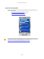
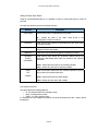
mControl has two main components. By default, they are installed on the same machine.
mControl (Automation) Service
•
•
•
Operating System
o Windows 2000
o Windows XP Home Edition
o Windows XP Professional
o Windows XP Media Centre Edition 2005
o Windows Vista
Microsoft.NET framework version 2.0 (or higher)
o To download visit: http://msdn.microsoft.com/netframework/downloads/default.aspx
Microsoft MDAC version 2.7 (or higher)
o To download visit: http://msdn.microsoft.com/ and search for “MDAC”
mControl (User Interface) Clients
•
•
•
•
•
Windows Vista Media Center – using Media Center Presentation Layer (MCPL)
Windows XP Media Center Edition (MCE) 2005 (including Roll-up 2)
Windows Mobile
Internet Explorer 6.0 (or higher)
Ultra-mobile PC (UMPC) Internet Explorer
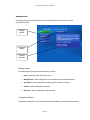
Media Center Interface
Screen Settings
•
Minimum 1024 x 768 screen setting
Supported Media Center Extenders
•
•
•
•
•
Xbox 360 (Media Center Extender)
Xbox Media Center Extender
HP x5400 Media Center Extender
Linksys Media Center Extender (Model WMCE54G)
Linksys DMA2x00 Extenders
Page 11
mControl v2 (Home Edition) User Manual
Supported Hardware
mControl supports a variety of automation systems. The following section summarizes the list of
automation systems supported.
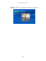
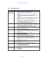
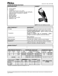
Security Cameras
Support for Linksys Internet cameras, including:
- Linksys models: WVC54GCA
Embedded Automation is proud to support Linksys products as
part of mControl.
For more information on Linksys, visit http://www.linksys.com/
Image Courtesy of Linksys
Support for Axis Internet cameras, including:
- Axis models: 206, 206M, 206W, 207, 207W, 210, 210A, 211, 211A, 212PTZ, 213PTZ, 214PTZ,
221 and 225FD
Embedded Automation is proud to support Axis Communication
products as part of mControl.
For more information on Axis Communication, visit
http://www.axis.com/
Image Courtesy of Axis Communication
Support for Panasonic Internet cameras, including:
- Panasonic models: BB-HCM331, BL-C111, BL-C131, BB-HCM515, BB-HCM511 and BB-HCM531A
Embedded Automation is proud to support Panasonic products
as part of mControl.
For more information on Panasonic, visit
http://www.panasonic.com/business/security/network_cameras.asp
Image Courtesy of Panasonic
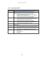
Support for D-Link Internet cameras, including:
- DCS-900, DCS-900W (please confirm the proper firmware and set-up software:
http://www.dlink.com/products/support.asp?pid=270)
- DCS-2100+
- DCS-3220 and DCS-6620
- DCS-5300W
Page 12
mControl v2 (Home Edition) User Manual
Embedded Automation is proud to support D-Link Corporation
products as part of mControl.
For more information on D-Link Corporation, visit
http://www.dlink.com/
Image Courtesy of D-Link Corporation
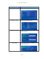
Security Systems
Support for Elk Products, Inc. technologies, including:
- ELK-M1G (Gold) Cross Platform Control
Embedded Automation is proud to support Elk Products, Inc.
products as part of mControl.
For more information on Elk Product, Inc., visit
http://www.elkproducts.com/index.html
Image Courtesy of Elk Products, Inc.
Support for Digital Security Controls (DSC) technologies, including:
- DSC PowerSeries Security Systems
Embedded Automation is proud to support Digital Security
Controls (DSC) products as part of mControl.
For more information on Digital Security Controls (DSC), visit
https://www.dsc.com/Home.aspx
Image Courtesy of Digital Security Systems (DSC)
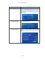
Support for Honeywell Security technologies, including:
- ADEMCO VISTA Commercial Burglary Partitioned Security System With Scheduling
Embedded Automation is proud to support Honeywell Security
products as part of mControl.
For more information on Honeywell Security, visit
http://www.security.honeywell.com/
Image Courtesy of Honeywell Security.
Page 13
mControl v2 (Home Edition) User Manual
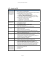
HVAC Systems
Support for HAI thermostats, including:
- Omnistat RC series thermostats
Embedded Automation is proud to support Home Automation, Inc.
(HAI) products as part of mControl.
For more information on Home Automation, Inc., visit
http://www.homeauto.com/Products/Omnistat/rc80.asp
Image Courtesy of Home Automation, Inc. (HAI) © 2006
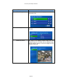
Support for RCS thermostats, including:
- TXB16 (X10) Thermostat
- TZ16 (Z-Wave) Thermostat
Embedded Automation is proud to support Residential Control
Systems Inc. products as part of mControl.
For more information on Residential Control Systems Inc., visit
http://www.resconsys.com/index.htm
Image Courtesy of Residential Control Systems Inc. © 2006
Support for Proliphix thermostats, including:
- Thermostat NT10e and NT20e
Embedded Automation is proud to support Proliphix Inc. products
as part of mControl.
For more information on Proliphix Inc., visit
http://www.proliphix.com/default.aspx
Image Courtesy of Proliphix Inc. © 2007
Page 14
mControl v2 (Home Edition) User Manual
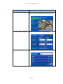
Support for Aprilaire thermostats, including:
- 8870 Communicating Thermostat
Embedded Automation is proud to support Aprilaire products as
part of mControl.
For more information on Aprilaire, visit http://www.aprilaire.com
Image Courtesy of Aprilaire
IR Support
Support for Global Caché Network Adapter technologies, including:
- GC-100-xx Network Adapters
- GC-IRL (IR Learner) – used to input IR commands
- GC-IRE (IR Extender) – used to input IR commands
- GC-RG1 (IR Receiver) – used to input IR commands
Embedded Automation is proud to support Global Caché products
as part of mControl.
For more information on Global Caché, visit
http://www.globalcache.com/
Image Courtesy of Global Caché © 2005
Support for USB UIRT IR Adapter technologies, including:
- USB UIRT IR adapter – used to learn and blast IR commands
Embedded Automation is proud to support USB UIRT products as
part of mControl.
For more information on USB UIRT, visit
http://www.usbuirt.com/overview.htm
Page 15
mControl v2 (Home Edition) User Manual
Irrigation Controllers
Support for SimpleHomeNet irrigation controllers, including:
- EZRain V1 Irrigation Controller
Embedded Automation is proud to support SimpleHomeNet
products as part of mControl.
For more information on SimpleHomeNet, visit
http://simplehomenet.com/
Image Courtesy of SimpleHomeNet © 2006
Voice Recognition Support
Support for One Voice Technologies, including:
- Media Center Communicator™ 2.1 software
Embedded Automation is proud to support One Voice
Technologies products as part of mControl.
For more information on One Voice Technologies, visit
http://www.onev.com/mcc/index.htm
Image Courtesy of One Voice Technologies © 2006
Page 16
mControl v2 (Home Edition) User Manual
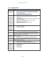
INSTEON Protocol
Embedded Automation is proud to support the INSTEON protocol
as part of mControl.
For more information on INSTEON, visit http://www.insteon.com/
Image Courtesy of SMARTHOME © 2003
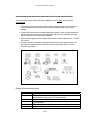
INSTEON Adapters
mControl supports multiple INSTEON adapters including:
¾
PowerLinc 2414U (USB) or 2414S (Serial)
¾
PowerLinc 2814U (USB) Timer
¾
Power Line Modem 2412U (USB) or 2412S (Serial)
For the Power Line Modem 2412U (USB), you will need to load the associated driver, as
provided by Smarthome. After loading the driver, the Power Line Modem 2412U will be
available as a COM port.
¾
SimpleHomeNet EZBridge (IP to Serial)
When using serial INSTEON adapters, please confirm that other drivers are not also using a serial
interface. For example, by default, mControl loads the serial driver of the X10 CM11A adapter. You
may need to unload the X10 CM11A driver if both adapters are using the same serial port to
ensure that there are no duplicate allocations of the serial port.
Page 17
mControl v2 (Home Edition) User Manual
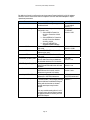
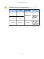
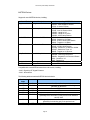
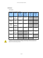
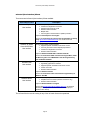
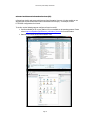
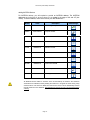
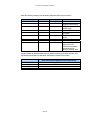
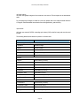
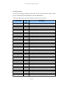
By default, mControl is configured to use the operate a PowerLinc 2414U or 2814U adapter
interface. Use the mServer.exe.xml file to adjust to use other INSTEON adapters or adjust
operational parameters.
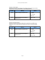
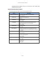
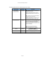
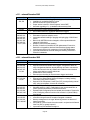
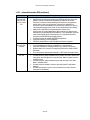
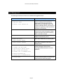
Parameter
load
ConnectUsing
COMPort
IPAddr
IPPort
STARTUP_CHECK_LINK
STARTUP_CHECK_STAT
DisableX10Control
MapX10ToINST
StartingHops
Meaning
Whether INSTEON adapter support is
loaded and used
Which communication port the adapter is
configured to use.
¾ Select USB for PowerLinc
2414U or PowerLinc 2814U
Timer
¾ Select SERIAL for PowerLinc
2414S, Power Line Modem
2412S or 2412U
¾ Select ETHERNET for
SimpleHomeNet EZBridge
If Port is SERIAL, defines the COM port
to be used.
If Port is ETHERNET, defines the IP
Address to be used.
If Port is ETHERNET, defines the IP port
to be used.
During start-up, ensure that INSTEON
devices within the mControl database
are included within the PLC’s link table.
During start-up, get the current status
value of the devices within the mControl
database.
Since the 2414x/2814x can do both
INSTEON and X10 control, use this
parameter to ignore all X10 activity.
Use this parameter to define X10
addresses to INSTEON addresses.
The default number of mesh hops to use
in communication. This is largely a timing
factor and allows for additional delays in
talking with devices that are located
several mesh hops away from the
adapter.
You may consider setting this to 2 or 3 if
you have many devices that are located
on different phases or far away from the
INSTEON adapter.
Page 18
Options
Y = loaded
N = not loaded
Default = Y
USB, SERIAL or
ETHERNET
Default = USB
COM1, COM2, …
Default = COM1
Default = 192.168.0.65
Default = 8002
true, false
Default = true
true, false
Default = true
true, false
Default = false
“<X10 address>=
<INSTEON addresss>”
0,1,2 or 3
Default = 1
mControl v2 (Home Edition) User Manual
There are different versions of the PowerLinc 2414x/2814x PowerLinc adapters. The following
table describes the versions and their compatability with mControl:
Adapter Version
Adapter Firmware
Version
Adapter SALad
Version (download
software area)
Comments
Preferred for mControl
compatibility.
v1.7 or higher
v2.13
TimerCoreApp v1.12
v1.6
v1.4 or below
v2.12
v2.09 or below
Page 19
CoreApp
TimerCoreApp v1.06
or higher must be
used to receive
paddle feedback from
switches
Will work, but some
INSTEON commands
may be lost due to
non-queuing capability
of the older firmware.
mControl v2 (Home Edition) User Manual
INSTEON Devices
Support for most INSTEON devices, including:
mControl Module
Appliance Module
Description
ApplianceLinc Modules
Dimmable Module
LampLinc Modules
On/Off Switch
SwitchLinc On/Off Switches
Dimmer Switch
SwitchLinc Dimmers
KeyPad Modules
Multikey Modules
Irrigation Module
IO Modules
Irrigation Modules
IO Modules
Corresponding INSTEON Devices
2456S3 - ApplianceLinc V2
2856S3 - ICON Appliance On/Off
2475S - In-LineLinc Relay
2475D - In-LineLinc Dimmer
2474D - Icon SL Dimmer Inline
2456D3 - LampLinc V2
2456D2 - LampLinc V2 2-Pin
2856D2 - ICON Lamp Dimmer
2473S - OutletLinc
2476S - SwitchLinc V2 Relay
2876S - ICON In-Wall On/Off Switch
2466S - ToggleLinc V2 Relay
2476D - SwitchLinc V2 Dimmer
2876D - ICON In-Wall Dimmer
2476DH - SwitchLinc V2 Dimmer 1000W
2476ST - SwitchLinc Timer V2
2466D - ToggleLinc V2 Dimmer
2486D - KeypadLinc V2 Dimmer
2886DB - ICON Keypad Dimmer
2486Dx - KeypadLinc V2 Dimmer 8-Button
2430 - ControLinc V2
2440 - RemoteLinc
5010A - EZRain V1 Irrigation Controller
xxxxx – EZIOxx I/O Modules
Compatible with most INSTEON transceivers and remotes, including:
- 2442 - SignaLinc RF Signal Enhancer
- 2443 - AccessPoint
The following table summarizes INSTEON device behavior:
Previous
State
OFF
OFF
Command
Result
ON
BRIGHT *
On at Preset On value
ON at x%, where x is defined by the mControl dim/bright
granularity for the device
OFF
DIM *
OFF
OFF
OFF
OFF
ON
ON
ON at 100%
ON
BRIGHT *
ON – (y + x)%, where x is defined by the mControl dim/bright
granularity for the device and y is the previous level. Maximum
value is 100%
ON
DIM *
ON – (y – x)%, where x is defined by the mControl dim/bright
granularity for the device and y is the previous level
ON
OFF
OFF
* For non-appliance devices only
Page 20
mControl v2 (Home Edition) User Manual
Hybrid INSTEON and X10 Environments
X10 to INSTEON Address Translations
To provide compatibility with other X10-based systems, mControl’s MapX10ToINST functionality
allows incoming X10 addresses to directly affect a corresponding INSTEON address. This
functionality is done at the “driver” level of mControl – no automation or macros are required.
MapX10ToINST recognizable values are:
X10 address – required X10 address to listen for and translate into an INSTEON address
(does not have to be in the mControl database)
separator – single character to separate the X10 and INSTEON address. Valid characters are
‘:’, ‘-’, ‘=’, ‘ ’ or ‘|’.
INSTEON address – INSTEON address to translate the X10 address to (does not have to be
in the mControl database)
In the following sample, two X10 addresses, B3 and B4, are mapped to INSTEON addresses,
00.EF.F0 and 00.EF.F1, respectively – they are separated by a ‘|’ character.
<adapter base="2414U" load="Y" assembly="mServerAdapters.dll"
driver="EmbeddedAutomation.mServer.Adapters.Insteon2414Manager">
<aparam name="DISPLAY-AS" value="2414U"/>
<aparam name="DESCRIPTION" value="INSTEON PowerLinc USB adapter"/>
<aparam name="SUPPORTS" value="INSTEON|X10"/>
<aparam name="APROTOCOL" value="INSTEON"/>
<aparam name="PORTS" value="USB"/>
<aparam name="MapX10ToINST" value="B3=00.EF.F0|B4=00.EF.F1"/>
</adapter>
Adapter Considerations for Hybrid INSTEON and X10 Environments
PowerLinc 2414x/2814x controllers are capable of X10 and INSTEON communications.
For optimum performance, especially within large or noisy hybrid X10 and INSTEON
environments, consider using the PowerLinc 2414x/2814x solely for INSTEON messaging. Use
the DisableX10Control parameter to disable X10 communication through the PowerLinc
2414x/2814x adapter and use a dedicated X10 adapter (e.g., CM11A or CM15A) for X10
messaging.
mControl allows creation of devices with the same physical address (e.g, Device1 with address
X10=A1 and Device2 with address X10=A1). In this case, it is recommended that devices with the
same address use the same adapter and reference the same device type. Selecting different
adapters and device types, can result in erroneous behavior.
Page 21
mControl v2 (Home Edition) User Manual
Advanced INSTEON Functionality
Link Databases
Like all INSTEON devices, the PowerLinc 2414x/2814x adapter has a “link database” (this is
sometimes called the “PLC Database”). This link database has a list of all “linked” INSTEON
devices.
For security reasons, the PowerLinc 2414x/2814x Adapter automatically obfuscates all INSTEON
messages from devices not in the link database. Ostensibly, this is to ensure that your neighbor
can not see the operation of your devices but you will be able to see all activity associated with
your devices.
mControl can automatically link all entered devices entered within the PowerLinc 2414x/2814x
adapter’s link database.
To enable/disable automatic linking and status checking upon start-up of mControl, modify the
STARTUP_CHECK_LINK (add an entry in the link database at startup) and
STARTUP_CHECK_STAT (get the status of the device at startup) parameters within the
“mServer.exe.xml” file, located in the “C:\Program Files\Embedded Automation\mControl\server”
directory.
Please note, if you have a large database, upon start-up the automatic linking and status checking
process may take a few minutes. Normally, this is unnoticeable because this happens before an
mControl client is accessed.
mControl uses the following methods to update the PowerLinc’s 2414x/2814x link database:
Upon start-up, if STARTUP_CHECK_LINK is enabled, mControl tries to link all the
INSTEON addresses within the mControl database.
Upon entry of an INSTEON device using the Add/Edit Device page, mControl will attempt
linking of the new device
Upon deletion of an INSTEON device using the Edit Device page, mControl will attempt to
remove the link of the deleted device
Upon modification of an INSTEON address using the Edit Device page, mControl will
attempt to remove the link of the unused device and link the address of the new device
Page 22
mControl v2 (Home Edition) User Manual
Smarthome HouseLinc Software
Smarthome’s HouseLinc software is complementary to mControl. HouseLinc may be used to
programmatically set links for the PowerLinc 2414x/2814x adapter and/or remote devices. If this is
done, it is recommended that the STARTUP_CHECK_LINK parameter is disabled.
Links and Device Status
If devices are not linked, mControl can recognize status changes only if theses changes are
initiated by mControl – status changes from external sources, say a ControLinc or a SwitchLinc
paddle press, will not be recognized.
mControl uses the following methods to update the status of devices stored in the mControl
database and shown on the screen:
Upon start-up, immediately after the linking process, mControl inquires for the status of
each device and listens for the acknowledgement message
Upon each command or macro, mControl listens for the acknowledgement message
If the device is linked in the PLC Database, mControl is also able to listen for
acknowledgements sent by the device as a response to the initiating device.
While it is possible to poll for status for INSTEON devices, mControl does not use polling to ensure
that there is no additional traffic on the INSTEON bus. Generally speaking, Embedded Automation
believes that polling causes unnecessary traffic which may conflict with device to device
messaging – we believe that event-based messaging is best.
If mControl is not updating status of the device, the following problems may exist:
The device did not link during start-up or the add/edit process. It is recommended to either
re-start mControl, re-save the device using the Edit Device page or attempt manual
linking.
There is significant traffic or noise on the powerline and the PowerLinc 2414x/2814x
adapter did not receive the status (or acknowledgement) message. Consider moving the
adapter away from noisy electrical components (e.g., computer), relocate any X10 devices
that are in the adapter’s proximity (they can interfere with normal processing), reduce the
traffic on your INSTEON network by reducing the number of external links.
Page 23
mControl v2 (Home Edition) User Manual
Macro Triggering and Real-time Status Changes from SwitchLinc Paddle Presses
As shipped from the factory, the PowerLinc 2414x/2814x adapter can not “hear” paddle press
messages originating from SwitchLinc. As a result, mControl can not show any status changes
initiated by paddle presses on SwitchLinc devices.
To enable this, the PowerLinc 2414x/2814x and SwitchLinc must be linked to each other.
1. Link the SwitchLinc to the PowerLinc
As part of mControl normal operation, mControl will automatically create a link within the
PowerLinc 2414x/2814x link database upon entry of the SwitchLinc device.
2. Link the PowerLinc to the SwitchLinc
SwitchLinc devices will only send paddle press changes to devices linked to it. As shipped
from the factory, PowerLinc 2414x/2814x does not allow for “slave” links from other
devices, like SwitchLincs, due to limitations in the “SALad core application”, a software
application, which manages the interface between the INSTEON connection and the
computer. To enable this functionality, a new SALad core application must be downloaded
to the PowerLinc. Ensure the PowerLinc 2414x/2814x is using the TimerCoreApp (v1.06)
or higher.
Once these steps have been completed, it is possible to receive real-time information (<2 seconds)
from SwitchLinc devices. In addition, it is possible to use SwitchLinc On or Off paddle presses for
macro triggers.
For more detailed information, please refer to mControl Application Note 06-0001-A.
Setting Preset On and Ramp Rates
mControl allows users to set the Preset On and Ramp Rates for the following devices:
2876DB ICON SwitchLinc
2476D SwitchLinc v2.2
2476D SwitchLinc v2.0
2486D KeypadLinc
2456D3 LampLinc
Please refer to the Edit Device section of this manual for additional information.
Page 24
mControl v2 (Home Edition) User Manual
Z-Wave Protocol
Embedded Automation is proud to support the Z-Wave protocol as
part of mControl.
For more information on Z-Wave,
visit http://www.z-wavealliance.org/content/modules/Start/
Image Courtesy of Z-Wave Alliance © 2006
Z-Wave Adapters
Support for Z-Wave PC adapters, including:
- Intermatic Computer Interface (Model No. HA22 – USB)
- HomePro Computer Interface (Model No. ZCU010 – USB) by ACT
For the HomePro Computer Interface For best results, we recommend using Z-Wave v4.10 or
higher (Stationary Controller) firmware. Using older firmware may not provide feedback on device
changes and hence, real-time client updates and macro triggers may not operate correctly.
If you have not previously used a Z-Wave adapter, you may be required to install the associated
drivers – please refer to the documentation and software provided with your adapter. Upon
plugging in the adapter, you will be required to provide a location for the driver files to be installed.
Once the driver files are installed and your computer is rebooted, the adapters will be ready for use
with mControl.
Page 25
mControl v2 (Home Edition) User Manual
Z-Wave and mControl terminology differences should be noted:
For Z-Wave, “controllers” are used to manage a Z-Wave network. There are two types of
controllers, primary and secondary.
o As the name implies, primary controllers are the primary controllers of the Z-Wave
network and are used to set up the Z-Wave network and associated devices.
Primary controllers are typically portable devices, which can manage local (“short
range”) enrollment and un-enrollment of Z-Wave devices.
o A secondary controller contains information on the Z-Wave network and the
associated devices. Secondary controllers are allowed to communicate with the
existing network definition, but are not allowed to add or remove devices.
The PC-attached devices which are capable of sending Z-Wave protocols are typically
secondary controllers, though it is possible to configure these as primary controllers.
For mControl, all PC attached devices used to interface to a home automation protocol are
called adapters. Hence, as long as device is attached to the PC and is capable of sending
out Z-Wave protocol messages, and regardless of configuration as a Z-Wave primary or
secondary controller, in terms of mControl terminology, it is considered an adapter.
Real-time Information Display
mControl can receive status changes from devices in real-time, allowing for up-to-date status
information on devices and macro triggering. The speed of updates is dependent on the polling
rate defined for the Z-Wave driver. This rate is set within the mServer.exe.xml file.
<adapter base="ZWCTRL" load="Y" assembly="EA.ZWAVE.dll"
driver="EmbeddedAutomation.mServer.Adapters.ZWaveManager">
<aparam name="DISPLAY-AS" value="Z-Wave Controller"/>
<aparam name="Description" value="Z-Wave USB Controller"/>
<aparam name="Supports" value="ZWAVE"/>
<aparam name="AProtocol" value="ZWAVE"/>
<aparam name="Ports" value="USB|COM1|COM2|COM3|COM4"/>
<aparam name="IniPorts" value="USB"/>
<aparam name="DebugLevel" value="5"/>
<aparam name="PollingSeconds" value="10" note="zero means no polling.
Allowed range: {0-3600} seconds"/>
</adapter>
To ensure robust network use and to comply with regional requirements, polling rates
should be kept as high as possible – a simple rule of thumb is 1 second per device, so
for 30 devices, use 30 seconds.
Page 26
mControl v2 (Home Edition) User Manual
Z-Wave Devices
Support for most Z-Wave devices, including:
Device Type
Binary Switches
Multi-Level Switches
Thermostats
Devices Validated
Intermatic HA01: In-Wall Receptacle
Intermatic HA02: Plug-in Appliance Module
Intermatic HA04: Outdoor Lighting Module
Intermatic HA03: Plug-in Lamp Module
Intermatic HA06: In-Wall Switch/Dimmer
RCS TZ16 Thermostat
Works with the following Z-Wave devices, including:
Device Type
Remotes
Devices Validated
Intermatic HA07: Master Remote Control
Intermatic HA09: Handy Remote Control
Remotes can be used as Primary or Secondary controllers.
The following table summarizes multi-level Z-Wave device behavior:
Previous
State
OFF
OFF
Command
Result
ON
BRIGHT *
OFF
OFF
ON
DIM *
OFF
ON
ON
BRIGHT *
ON
DIM *
ON
OFF
On at Preset On value
ON at x%, where x is defined by the mControl dim/bright
granularity for the device
OFF
OFF
If below Preset On value, then goes to Preset On value,
else ON at 100%
ON – (y + x)%, where x is defined by the mControl dim/bright
granularity for the device and y is the previous level. Maximum
value is 100%
ON – (y – x)%, where x is defined by the mControl dim/bright
granularity for the device and y is the previous level
OFF
Page 27
mControl v2 (Home Edition) User Manual
Z-Wave Adapter Utility
mControl setup installs a utility, called the Z-Wave Adapter Utility, which can be used to quickly and
easily configure your Z-Wave adapter and associated network. Use the Z-Wave Adapter Utility to:
Connect to the adapter
Define the “controller” configuration for the adapter:
• Reset the adapter to act as a Z-Wave primary controller
• Reset the adapter to act as a Z-Wave secondary controller
• Receive network information from another controller (if the adapter is
configured as a secondary controller)
• Send network information to another controller (if the adapter is configured as
a primary controller)
Quickly add/remove devices to the Z-Wave adapter/controller.
Only one software component can be connected to the Z-Wave adapter at one time.
Upon starting the Z-Wave Adapter Utility and attempting to connect to the adapter, you
will be prompted to stop the mControl Automation Service.
Upon leaving the Z-Wave Adapter Utility, a dialog box will prompt you to restart the
mControl Automation Service.
The Z-Wave Adapter Utility is automatically installed and is accessible from the “Tools” section of
the mControl program area:
Page 28
mControl v2 (Home Edition) User Manual
Once started, the following Windows-based dialog box is shown:
Connection
Options
Controller
Options
Device
Options
mControl
Automation
Service
Options
Z-Wave
Adapter
Information
Connection Options
Port – select the COM or USB port on which the Z-Wave adapter is connected to.
(Only the COM ports that are available on the machine are shown.)
Devices Poll Interval (sec) – the polling rate for Z-Wave devices within the Z-Wave
Adapter Utility.
Note that this is a different setting than the mControl polling rate, which is set within the
mServer.exe.xml file.
Connect – connect to the selected Z-Wave adapter on the port specified.
Disconnect – disconnect from the Z-Wave adapter
Refresh Devices List – refresh the device list to the get latest information
Page 29
mControl v2 (Home Edition) User Manual
Controller Options
Reset Controller – use this button to configure the adapter as a Z-Wave primary
controller.
o There can only be one primary controller in your Z-Wave network.
o To add and remove devices, the primary controller must be located within a close
proximity to the devices being added or removed. Hence, it may not be prudent to
set your adapter as a primary controller.
Start Receive Configuration – use this button to receive network information from a
primary controller. This button will set the Z-Wave adapter to be a secondary controller.
o For example, if you are using a HA07 as a primary controller, you can transmit the
network information to the Z-Wave adapter connected to your PC. Press the
“Receive Configuration” button in the Z-Wave Adapter Utility, then press and hold
the “Include” button on the HA07. “Copy” will be shown in the LCD display.
Release the “Include” button. Press and release the Channel 1 ON/DIM button on
the primary controller. “TA” which stands for “Transmit ALL data” will be shown
next to the copy. After about 10 to 20 seconds, the Z-Wave Adapter Utility will
complete receiving all the network data and display it in the Z-Wave Adapter
Information window.
Cancel Receive Configuration – use this button to abort the “Start Receive
Configuration” request.
Start Send Configuration – use this button to send network information to a secondary
controller.
o For example, if you have configured the Z-Wave adapter as the primary, you may
want to transfer the network configuration to your HA07 remote.
Cancel Send Configuration – use this button to abort the “Start Send Configuration”
request.
Start Transfer Primary Role – use this button to transfer the network information and
primary role to another adapter. This button will set the Z-Wave adapter to be a secondary
controller.
Cancel Transfer Primary Role – use this button to abort the”Cancel Transfer Primary
Role” request.
Page 30
mControl v2 (Home Edition) User Manual
Device Options
If the adapter has been configured as a primary controller, the following Device Management
Options are available:
Start Add Device – use this button to initiate adding a Z-Wave device to the primary
controller (adapter).
Z-Wave devices may not be able to be added if there were previously associated with another network. In
this scenario, you may try to remove the device and then add the device.
Cancel Add Device – use this button to abort the process of adding a Z-Wave device to
the primary controller (adapter).
Start Remove Device – use this button to initiate removing a Z-Wave devices from the
primary controller (adapter).
Cancel Remove Device – use this button to abort the process of removing a Z-Wave
device from the primary controller (adapter.)
ID of Device To Replace, Remove or Rediscover – this display window provides a list of
devices in the network, which can be selected for replacement, deletion or rediscovery.
Replace Failed Node – use this button to replace a failed node. This button deletes the
node entry from the network and adds a replacement device with the address previously
used by the failed device. This is useful because deleting and then adding a device may
not result in the same node addressing within the network.
Delete Failed Node – use this button to delete a failed node from the network. This button
deletes the node entry from the network.
Rediscover Node – use this button to rediscover Z-Wave information about the node.
Please note, older adapters/firmware may have problems with unenrolling and then re-enrolling devices.
Please verify your network before adding devices to mControl.
Page 31
mControl v2 (Home Edition) User Manual
mControl Automation Service Options
Start – Start the mControl Automation Service. This button will typically be selected to
restart the service after completing configuration using the Z-Wave Adapter Utility and
disconnecting from the adapter.
Stop – Stop the mControl Automation Service. This button will typically be selected before
connecting to the adapter.
Restart – Restart the mControl Automation Service.
Service Status – displays the status of the mControl Automation Service
Exit – Exit the Z-Wave Adapter Utility
About … – Information about the Z-Wave Adapter Utility
Z-Wave Adapter Information
Network Configuration – this window provides the network configuration stored within
the Z-Wave Adapter.
Log – this window provides a real-time display of network activity, as viewed by the ZWave adapter.
Page 32
mControl v2 (Home Edition) User Manual
Adding Z-Wave Devices to mControl
Use the following methods to add Z-Wave devices to mControl (shown in order of typical use):
If the Z-Wave adapter is defined as a secondary controller
If not already set, use the Z-Wave Adapter Utility to define the Z-Wave adapter as a secondary
controller.
With the adapter configured as a secondary controller, you will not be able enroll or un-enroll
devices from within mControl. You must use the Z-Wave Adapter Utility to receive the network
information, including devices defined on the network, from a primary controller. Follow the
instructions provided on your primary controller to replicate (copy) the primary controller
settings to a secondary controller to initiate this process.
Once this has been completed, use the mControl Edit Device page to associate device names
to the corresponding Z-Wave network device enrolled IDs.
If the Z-Wave adapter is defined as a primary controller
If not already set, use the Z-Wave Adapter Utility to define the Z-Wave adapter as a primary
controller.
Once the Z-Wave adapter has been reset as a primary controller, devices IDs can be directly
enrolled or un-enrolled to the adapter (primary controller). This can be done from either the ZWave Adapter Utility or directly within mControl (Edit Device page).
Once this has been completed, use the mControl Edit Device page to associate device names
to the corresponding Z-Wave network enrolled device IDs.
Page 33
mControl v2 (Home Edition) User Manual
Removing Z-Wave Devices from mControl
Use the following methods to remove Z-Wave devices from mControl (shown in order of typical
use):
If the Z-Wave adapter is defined as a secondary controller
Remove the devices from your primary controller. You must use the Z-Wave Adapter Utility to
receive the updated network information from the primary controller. Follow the instructions
provided on your primary controller to replicate (copy) the primary controller settings to a
secondary controller to initiate this process.
Once this has been completed, you must use the mControl Edit Device page to delete the
corresponding Z-Wave network device IDs. This removes the device from the mControl
database.
If the Z-Wave adapter is defined as a primary controller
This can be done from either the Z-Wave Adapter Utility or directly within mControl (Edit
Device page).
From the Z-Wave Adapter Utility – select the “Start Remove Device” button to remove the
device from the network.
From within mControl (Edit Device page) – select the “Unenroll” button to remove the
device from the network.
Once this has been completed, you must use the mControl Edit Device page to delete the
corresponding Z-Wave network device IDs. This removes the device from the mControl
database.
Page 34
mControl v2 (Home Edition) User Manual
Rako Protocol
Embedded Automation is proud to support the Rako protocol as
part of mControl.
For more information on Rako, visit http://www.rakocontrols.com/
Image Courtesy of Rako Controls © 2007
Rako Adapters
mControl supports the following Rako adapters:
¾
RAV232+ Bi-Directional RS232-RF Interface
By default, the RAV232+ adapter driver is disabled. Use the mServer.exe.xml file to adjust
parameters associated with RAV232+ adapter operation:
Parameter
load
Meaning
Whether the adapter is loaded and used
Options
Y = loaded
N = not loaded
Default = N
COMPort,
BAUD
House Code
Which communication port and baud rate the
adapter is configured to use
Default = COM1
Which Rako House Code to use
Default = 1
Default = 9600
When using serial Rako adapters, please confirm that other drivers are not also using a serial
interface. For example, by default, mControl loads the serial driver of the X10 CM11A adapter. You
may need to unload the X10 CM11A driver if both adapters are using the same serial port to
ensure that there are no duplicate allocations of the serial port.
Rako Devices
Support for most Rako devices, including:
Devices
Multi-level switches – for example, RDL500 (500VA Inductive Dimmer)
Binary switches
Page 35
mControl v2 (Home Edition) User Manual
X10 Protocol
X10 Adapters
Support for most X10 adapters, including:
Adapter
PowerLinc
1132Cx
PowerLinc
2414x
CM11A,
CM11U,
CM12U
CM15A
Protocol
X10
Command
Send
Command
Receive
Command
Send
Command
Receive
(Power line)
(Power line)
(RF)
(RF)
Supported
Supported
Not supported
Not Supported
Supported
Supported
Not supported
Not Supported
Supported
Supported
Not supported
Not Supported
Supported
Supported
Supported
Supported
Not Supported
Not Supported
Supported
Supported
Not Supported
Not Supported
Supported
Not supported
Not Supported
Not Supported
Not Supported
Supported
(Standard)
X10
(Standard)
X10
(Standard,
Extended)
X10
(Standard)
CM19A
X10
(Standard)
CM17A
X10
(Standard)
W800RF32A
X10
For adapters which do not have RF receive capability, to receive X10 RF messages you must use an X10
Transceiver (e.g., TM751) to translate the X10 RF signal to X10 PLC signal – once on the powerline, the
adapter can receive the incoming command.
Page 36
mControl v2 (Home Edition) User Manual
PowerLinc 1132Cx Adapter
By default, the PowerLinc 1132Cx adapter driver is disabled. Use the mServer.exe.xml file to
adjust parameters associated with PowerLinc 1132Cx adapter operation:
Parameter
load
Meaning
Whether the adapter is loaded and used
Options
Y = loaded
N = not loaded
Default = N
Port
Which communication port the adapter is
configured to use
Default = USB
PowerLinc 2414x/2814x Adapter
By default, the PowerLinc 2414x/2814x adapter driver is enabled for use on USB. Use the
mServer.exe.xml file to adjust parameters associated with PowerLinc 2414x/2814x adapter
operation:
Parameter
load
Meaning
Whether the adapter is loaded and used
Options
Y = loaded
N = not loaded
Default = Y
Port
Which communication port the adapter is
configured to use
Page 37
USB, COMx
Default = USB
mControl v2 (Home Edition) User Manual
CM11A X10 Adapter
By default, the CM11A adapter driver is enabled for use on COM1 with a dedicated connection to
the port to allow receipt of incoming X10 commands. Use the mServer.exe.xml file to adjust
parameters associated with CM11A adapter operation:
Parameter
load
Meaning
Whether the adapter is loaded and used
Options
Y = loaded
N = not loaded
Default = Y
Port
KeepPortOpen
Which communication port the adapter is
configured to use
COMx = COM port #
Whether this is a dedicated connection to the
port, or only open when a send is required. If
“false” then incoming X10 signals will not be
received
true = dedicated
Default = COM1
false = non-dedicated
Default = true
CM17A X10 Adapter
By default, the CM17A adapter driver is not enabled. Use the mServer.exe.xml file to adjust
parameters associated with CM17A adapter operation:
Parameter
load
Meaning
Whether the adapter is loaded and used
Options
Y = loaded
N = not loaded
Default = N
Port
KeepPortOpen
Which communication port the adapter is
configured to use
COMx = COM port #
Whether this is a dedicated connection to the
port, or only open when a send is required.
true = dedicated
Default = COM1
false = non-dedicated
Default = false
Page 38
mControl v2 (Home Edition) User Manual
CM15A/CM19A X10 Adapter
The CM15A and CM19A adapters use the same mControl driver. By default, the mControl driver
for these adapters is enabled, with powerline as the sending method.
To use the CM15A and CM19A adapter, you must install the 3rd party software. The mControl driver for these
adapters uses the “ActiveHome Script” software provided by X10. This 3rd party software can be found in the
C:\Program Files\Embedded Automation\mControl\third party\X10 directory.
Additionally, to use the CM19A adapter, you will need to:
¾ Install the CM19A wireless drivers, also available in the C:\Program Files\Embedded
Automation\mControl\third party\X10 directory, called x10drivers.exe
¾ Set the default send method to be RF (since the CM19A is incapable of sending via powerline)
Use the mServer.exe.xml file to adjust parameters associated with CM15A/M19A adapter
operation:
Parameter
load
Meaning
Whether the adapter is loaded and used
Options
Y = loaded
N = not loaded
Default = Y
SendThrough
On which media are mControl X10 send
commands transmitted
¾
CM15A can send either via RF or PLC
¾
CM19A can only send via RF
PLC = via powerline
RF = via wireless/RF
Default = PLC
W800RF32A X10 Adapter
By default, the W800RF32A adapter driver is not enabled. Use the mServer.exe.xml file to adjust
parameters associated with W800RF32A adapter operation:
Parameter
load
Meaning
Whether the adapter is loaded and used
Options
Y = loaded
N = not loaded
Default = N
Port
KeepPortOpen
Which communication port the adapter is
configured to use
COMx = COM port #
Whether this is a dedicated connection to the
port, or only open when a send is required.
true = dedicated
Default = COM1
false = non-dedicated
Default = false
Page 39
mControl v2 (Home Edition) User Manual
Alternate Adapter Resolution
If the adapter associated with the device is not found, mControl will automatically search for other
available and capable adapters to send X10 commands. The search order for alternate adapter is
done alphabetically.
Consider the following example:
¾ The following adapters are enabled within the mServer.exe.xml file and connected to the
computer: 2414X (INSTEON), CM11A and CM15A.
¾ There is a device at X10 address A2 which has been configured to use the CM11A
¾ The CM11A becomes unavailable – for example, it is disconnected
¾ A command to the device at X10 address A2 will be routed via the 2414X (since it is
alphabetically before CM15A)
X10 Devices
Support for most X10 devices, including:
mControl Module
Description
X10_BINSW
(Standard)
X10_DIMMER
(Standard)
X10_EXTDIMMER
(Extended)
X10_SENSOR
X10_RELAY
X10_THERMOS
X10 On/Off Switch/Module
X10 Dimmable Switch/Module
X10 2-Way Dimmable Switch/Module
X10 Motion Sensor
X10 I/O Module
X10 Thermostat
Example X10 Devices
AM12U – Plug-in Appliance Module
AM466 – Appliance module
LM12U – Plug-in Lamp Module
LM465 – Lamp module
LM14A (LW12) – 2-Way Lamp Modules
Leviton Extended X10 Modules
MS14A - EagleEye Motion Sensor
UM506 – Universal Module
RCS TXB16 X10 Thermostat
Compatible with most X10 transceivers, including:
- W800RF32A – Wireless RF Transceiver
- RR501 - Transceiver Module
- TM13U - RF Transceiver
- TM751 - RF Transceiver
Compatible with most X10 remotes, including:
- HR12A - PalmPad Remote Control
- KR19A - Remote Control Module (Keychain)
- KR22A - Remote Control Module - RSS18 - Remote Wall Switch
- SS13A - Remote Wall Switch
- SS15A - Remote Wall Switch
- UR73A - Universal Remote with X10
Page 40
mControl v2 (Home Edition) User Manual
The following table summarizes X10 device behavior:
Previous
State
OFF
OFF
Command
Result
ON
BRIGHT *
ON – 100%
Standard X10: ON – 100%
Extended X10: ON – x%, where x is defined by mControl
dim/bright granularity for the device.
OFF
DIM *
Standard X10: ON – 100%
Extended X10: ON – 0%, where x is defined by mControl
dim/bright granularity for the device.
OFF
OFF
OFF
ON
ON
Standard X10: ON – at previous level (status will show 100%)
Extended X10: 100%
ON
BRIGHT *
ON – (y + x)%, where x is defined by the mControl dim/bright
granularity for the device and y is the previous level
ON
DIM *
ON – (y – x)%, where x is defined by the mControl dim/bright
granularity for the device and y is the previous level
ON
OFF
OFF
* For non-appliance devices only
Leviton X10 Devices
Embedded Automation is proud to support Leviton Mfg. Company
Inc. X10 products as part of mControl.
For more information on Leviton Mfg. Company Inc.,
visit http://www.leviton.com/
Image Courtesy of Leviton Mfg. Company Inc.
mControl provides extended X10 support for Leviton dimmable devices including:
- Dimming Switches (e.g., HMC10)
- Dimming Modules (e.g., HCP03)
Limitations and Recommendations
1. All adapters must be attached to the PC where the mControl Automation Service is
installed.
2. For hybrid X10 and INSTEON environments, consider using an X10 adapter for X10
incoming/outgoing messages and the INSTEON adapter for INSTEON only
incoming/outgoing messages.
Page 41
mControl v2 (Home Edition) User Manual
mControl Installation
Step 1 - Install mControl software
If you are installing mControl for the first time, skip directly to the “Download the Latest Version of
mControl” step.
mControl Trial Version
mControl v2 (Home Edition) is provided for a 30-day trial from the Embedded Automation web
site. A copy-protection mechanism manages this limitation. mControl will periodically show the
number of days remaining in the trial when the “Zone View” screen is accessed. The trial version
of mControl offers full software functionality for the duration of the trial.
Upon expiration, mControl will continue to operate as usual, however, automation commands will
only be sent to the first defined device.
Any re-installation or tampering with system date and/or the mControl license will cause
automatic expiration of the copy protection. Please contact Embedded Automation to extend your
30-day trial by emailing [email protected].
Page 42
mControl v2 (Home Edition) User Manual
Upgrading mControl
Whether you are using a trial version of mControl or a purchased license of mControl, you can upgrade
to a more recent version of mControl.
If you are upgrading mControl to a more recent version, please uninstall the previous version. The
mControl uninstall process will not remove any of your existing information – all zone, device, adapter
and license information will be kept for subsequent versions. In addition, mControl makes a backup of
your key files in the \backup directory.
Uninstalling mControl from Windows XP Systems
Use the Windows XP’s “Add or Remove Programs” utility to uninstall the previous version. To use this
utility, press the Start button, then select Control Panel and finally select “Add or Remove Programs”.
Cursor to mControl and press the “Remove” button to uninstall the previous version.
Page 43
mControl v2 (Home Edition) User Manual
Uninstalling mControl from Windows Vista Systems
Use the Windows Vista’s “Programs and Features” utility to uninstall the previous version. To use this
utility, press the Start button, then select Control Panel and finally select “Programs and Features”.
Cursor to mControl and press the “Uninstall” button to uninstall the previous version.
Uninstalling mControl from Windows Home Server Systems
Use the Windows Home Server Settings utility to uninstall the previous version. To use this utility, start
the Windows Home Server Console, then select Settings and finally select the “Add-ins” option and the
“Installed” tab. Cursor to mControl and press the “Uninstall” button to uninstall the previous version.
Page 44
mControl v2 (Home Edition) User Manual
Downloading the Latest Version of mControl
As a customer (or as a trial user), the first thing that you will need to do is download the most recent
mControl version from the Embedded Automation website (http://www.EmbeddedAutomation.com).
Once the download has initiated, “Save” mControl to your hard drive – for example, in the “My
Received Files” area.
Page 45
mControl v2 (Home Edition) User Manual
The downloaded file is a ZIP file, so you must use WinZip or equivalent to extract the contents.
You can not install mControl without first extracting the necessary files.
Page 46
mControl v2 (Home Edition) User Manual
Installing mControl
Installing mControl on Windows XP and Windows Vista Systems
You must be logged on as an administrator to install mControl.
Under Windows Vista, with User Account Control (UAC) enabled, you may be prompted to enable
mControl installation to start.
To install on Windows XP or Windows Vista systems, select the Win2K_XP_Vista directory. Then
simply use the mControlSetup.msi file (via a double-click) to install mControl.
The installation process can take several minutes and will automatically install all of the software
required for mControl. Any changes, for example, upgrading to the latest version of the mControl
database, are also automatically done as part of the installation process.
Page 47
mControl v2 (Home Edition) User Manual
You must agree with the End-User License Agreement (EULA) to continue installation. Please read
and accept to continue.
After confirmation of these settings, mControl will be installed. This may take several minutes.
Page 48
mControl v2 (Home Edition) User Manual
Once completed, the Readme.rtf file will be shown. This file provides information on your mControl
software, including:
Terms and Conditions of Use
How to install your user license (from CD or online purchase)
How to contact Embedded Automation technical support
Information on mControl versions
After reading the readme.rtf file, the installation will be complete.
Page 49
mControl v2 (Home Edition) User Manual
Installing mControl on Windows Home Server Systems
To install on Windows Home Server systems, select the WHS Setup directory.
Copy the mControl Installer to Windows Home Server
Logon to your Windows Home Server system and copy the mControl Add-in for Windows Home Server
installer, called “mControlWHS_Setup.msi” to the “\Software\Add-ins” shared directory.
Page 50
mControl v2 (Home Edition) User Manual
Using Internet Explorer, logon to your Windows Home Server console and access the Windows Home
Server console using the Remote Access to Windows Home Server Console under the Computers tab.
Use the Windows Home Server Add-in Manager to Install mControl
Logon to your Windows Home Server system and use the Settings button to access the Add-in
management functions of Windows Home Server.
Page 51
mControl v2 (Home Edition) User Manual
Select mControl and press the “Install” button to install the mControl Add-in for Windows Home
Server.
Restricting User Access to mControl
To prevent improper user access, select and set the most suitable authentication method. By default,
mControl is available to all external users.
• Logon locally to your WHS machine.
• Go to "Administrative Tools" and access "Internet Information Services" (IIS)
• Using the navigation tree, locate mControl under the "Default Web Site".
• Right-click and select "Properties" and then select the "Directory Security" tab. Select the "Edit
..." button in the "Anonymous Access and Authentication" section
• Turn off "Anonymous Access" and select the "Authentication" method best suited for you.
To understand authentication choices:
http://en.wikipedia.org/wiki/Internet_Information_Services#Authentication_mechanisms
Page 52
mControl v2 (Home Edition) User Manual
mControl Installation Information
Default Install Locations
mControl is installed in the following default directory locations:
•
For Windows XP and Windows Vista: C:\Program Files\Embedded Automation\mControl
•
For Windows Home Server: C:\Inetput\wwwroot\mControl
Installed mControl Components
The following software components are installed by the mControl Installer:
Component
Windows XP or Windows Vista
mControl
The mControl Automation Service is the
automation engine for mControl. It
includes a web server for all the various
clients. This component is installed as a
Windows service.
The mControl Automation Service is the
automation engine for mControl. It
includes a web server for all the various
clients. This component is installed as a
Windows service.
File: mServer.exe
File: mServer.exe
Location: <Install Directory>\server
Location: <Install Directory>\server
The mControl Editor Utility allows for
spreadsheet-like editing of mControl
database values.
The mControl Editor Utility allows for
spreadsheet-like editing of mControl
database values. Installed as component
of the Windows Home Server Console
Automation Service
mControl Editor
File: mControlEditor.exe
Windows Home Server
Location: <Install Directory>\bin
mControl
Service Manager
The mControl Service Manager provides
a user interface to manage the operation
of the mControl Automation Service.
File: mServerUtil.exe
Location: <Install Directory>\bin
mControl Z-Wave
Adapter Utility
The mControl Z-Wave Adapter Utility is a
configuration utility for managing Z-Wave
network adapters.
The mControl Service Manager provides
a user interface to manage the operation
of the mControl Automation Service.
Installed as component of the Windows
Homer Server Console
Not installed – to use, install mControl on
a different machine and use this utility.
File: ZWaveUtil.exe
Location: <Install Directory>\bin
One Voice to
mControl Bridge
The One Voice to mControl Bridge
provides a link between One Voice’s
Media Center Communicator voice
recognition system and mControl,
allowing execution of mControl
commands and macros by voice.
File: mControlOV.exe
Location: <Install Directory>\bin
Page 53
Not installed.
mControl v2 (Home Edition) User Manual
Installed 3rd Party Software Components
For convenience, the following third party software components are copied to the mControl directory
system, but require installation separately:
Component
X10 ActiveHome
Scripting System
Description
Driver software, provided by X10, to allow software, like mControl,
to programmatically communicate with a X10 CM15A or CM19A
adapter.
File: ahscript_setup.exe
Location: C:\Program Files\Embedded Automation\mControl\third
party\X10
Axis IP Cameras
ActiveX component
ActiveX component to allow mControl to display video stream from
Axis cameras:
File: ahscript_setup.exe
Location: C:\Program Files\Embedded Automation\mControl\third
party\Axis
It may be necessary to install other components for use with mControl.
¾ Drivers for Z-Wave adapters
¾ Microphone or speaker drivers
¾ Some IP Cameras will require installation of the streaming video components (ActiveX)
Page 54
mControl v2 (Home Edition) User Manual
Step 2 - Start mControl software
Before Starting mControl
To ensure proper operation of mControl, please do the following:
¾
It is highly recommended that you delete all content from your Temporary Internet Files
location, before installation, to avoid any conflicts with previous content.
¾
Configure firewall settings to permit “mserver.exe” and ports 29990-29995.
Starting mControl for Internet Explorer
You can start mControl by using the Windows “Start” button, then the “All Programs” option, then the
“mControl” folder and finally, the “mControl” program.
Alternatively, you can also use Internet Explorer. Open Internet Explorer (IE) and enter the following
line in the address bar, http://localhost:29990/Default.aspx. For users of the mControl Add-In for
Windows Home Server or to access mControl from a different PC, replace “localhost” with the IP of the
PC that mControl is installed on.
Page 55
mControl v2 (Home Edition) User Manual
Starting mControl within Media Center
You can access mControl by selecting “More Programs” area within “Media Center”.
Page 56
mControl v2 (Home Edition) User Manual
Step 3 – Activating mControl
To activate your software, you will have to purchase a software license. Upon completing your
purchase, you will be emailed a new license file, or for those retailers which provide a CD, the license
file will be on your CD. This license file is not activated and you will have 10 days to activate this file.
mControl License from a Purchased CD
If you have purchased mControl on a CD, simply install the CD – your mControl license will be
automatically installed.
¾ After installation, you may consider upgrading to the latest version of mControl, as outlined in
Step 1.
If you have a more recent trial version installed already, all you need to do is copy the license file from
the CD:
¾ Copy mServer.exe.lic.cpy file located in the root directory of the CD and paste it to your
desktop.
¾ Rename the mServer.exe.lic.cpy file located on your desktop to mServer.exe.lic.
¾ Copy the file which you have renamed to mServer.exe.lic to C:\Program
Files\EmbeddedAutomation\mControl\Server. Please ensure that you replace the trial license
(also called mServer.exe.lic) with the purchased license.
¾ Once the purchased license is copied to the proper location, mControl must be restarted to
use the new license. Reboot the computer or use the mControl Service Manager to restart
mControl.
Please ensure that both the mServer.exe.lic (mControl License) and the mServer.exe.lic.cpy
(mControl License back-up) exist in the C:\Program Files\EmbeddedAutomation\mControl\Server
directory.
Page 57
mControl v2 (Home Edition) User Manual
mControl License from an Online Purchase
mControl License on Windows XP or Windows Vista
If you have purchased mControl online, you will be emailed a license. This file is called
mServer.exe.lic.
¾ If you haven’t already, download the latest version of mControl and install it.
¾ Copy the mServer.exe.lic file and paste it into the following location: C:\Program
Files\EmbeddedAutomation\mControl\Server. Please ensure that you replace the trial license
(also called mServer.exe.lic) with the purchased license.
¾ Once the purchased license is copied to the proper location, mControl must be restarted to
use the new license. Reboot the computer or use the mControl Service Manager to restart
mControl.
mControl License on Windows Home Server
If you have purchased mControl online, you will be emailed a license. This file is called
mServer.exe.lic.
¾ If you haven’t already, download the latest version of mControl and install it.
¾ Copy the mServer.exe.lic file and paste it into your \\software share
¾ Use Remote Desktop to connect to your Windows Home Server machine
¾ Move the mServer.exe.lic file from your \\software share to the following location:
C:\Inetpub\wwwroot\mControl\Server. Please ensure that you replace the trial license (also
called mServer.exe.lic) with the purchased license.
¾ Once the purchased license is copied to the proper location, mControl must be restarted to
use the new license. Reboot the computer or use the mControl Service Manager to restart
mControl.
Page 58
mControl v2 (Home Edition) User Manual
Activating the mControl License
Activating the mControl License using mControl for IE
Once mControl for IE has been restarted, you will be prompted to activate your purchased license. This
activation process will remove all time restrictions from the software. You have 10 days to complete this
activation.
Upon selecting to activate, you will be sent to the “Activation” page, where the mControl license can be
activated.
Page 59
mControl v2 (Home Edition) User Manual
To perform a web activation, press the “Activate” button beside the “Automatic via web” label. Once
pressed, mControl will automatically download the special codes to activate the mControl license.
Web activation may take several seconds – please be patient – DO NOT press the “Activate”
button multiple times.
Once successful, the box at the bottom left of the screen will turn green.
Page 60
mControl v2 (Home Edition) User Manual
Activating the mControl License using mControl Editor
Once mControl Editor has been started, you will be prompted to activate your purchased license. This
activation process will remove all time restrictions from the software. You have 10 days to complete this
activation.
To perform a web activation, press the “Auto Activate” button. Once pressed, mControl will
automatically download the key codes to activate the mControl license.
Page 61
mControl v2 (Home Edition) User Manual
Using Manual Activation
Manual activation should be used when there is no Internet access available. From the mControl Editor
select the “Manually Activate” to send an email with the required information to Embedded Automation.
Embedded Automation will send a set of key codes to activate your license.
Page 62
mControl v2 (Home Edition) User Manual
Moving mControl to a New Computer
The activated license will be associated to the machine on which mControl is installed. To
move the license to another machine, you will have to contact Embedded Automation.
To move mControl to a new computer, you must:
¾ Download and install the latest version of mControl
¾ Stop the mControl (Automation) Service using the mControl Service Manager.
¾ Copy the mControl database file, called mHome.mdb, located in the C:\Program
Files\Embedded Automation\mControl\data directory to the new computer
¾ Use the original license provided on CD or via email for the new computer. You can not use
the license from the existing computer because, once activated, it is only usable by that
computer. You are allowed 2 activations per license.
¾ If you have modified any of the XML files (e.g., mServer.exe.XML or mControlDataSet.XML),
you must copy them to the new computer.
¾ Finally, for mControl to recognize the database, license and XML files, it must be restarted.
Use the mControl Service Controller to restart mControl or simply reboot the new computer.
Using mControl with a Dial-up Internet Connection
Since the mControl UI client is a web-based interface, Windows and Internet Explorer assume an
active Internet connection. It is possible to use mControl without an active Internet connection. If you
are running mControl without an active Internet connection, for example, if you normally use dial-up to
connect to the Internet. Use the following guidelines:
Use the mControl short cuts provided under the “All Programs …” section. This will work for
either running mControl using Internet Explorer or the Media Center interface. For Media
Center users, you can also select mControl from the “More Programs” area.
Please ensure that the “Work Offline” setting is not selected. This option is found under the
“File” menu option in Internet Explorer. If “Work Offline” is checked, you may receive frequent
reminders to connect to the Internet if there is no active Internet connection already
established.
For dial-up customers, we recommend using the “Dial whenever a network connection is not
present” setting. This setting can set using Internet Explorer “Tools” menu option, then
selecting “Internet Option” under the “Connection” tab.
Page 63
mControl v2 (Home Edition) User Manual
Using mControl Software
mControl Components
mControl (Automation) Service
The mControl Automation Service, as the name implies, manages the automation sub-system for
mControl. The mControl Service has a built-in web server and “serves” the user interfaces to the
mControl Clients.
The mControl Automation Service runs as a Windows Service called “mHome Automation Service” –
the process name for the mControl Service is “mServer.exe”. The mControl Service will run
automatically upon boot-up, does not require any user to be logged into Windows and will run until the
PC is turned off.
The mControl (Automation) Service should be installed on a computer which:
¾ Is “Always On”. If turned off, macros can not run
¾ Has the proper interfaces (e.g., USB, serial, Ethernet) to command devices and protocols
¾ Also, it is useful to minimize other software which may intrude on mControl operation
The mControl Service manages all macro operation. Hence, the PC must be on and mControl Service
must be running, for all macros to execute at their required times and triggers.
Page 64
mControl v2 (Home Edition) User Manual
mControl (User Interface) Clients
There are several mControl (User Interface) Clients available:
User Interface Client
Internet Explorer
User Interface
Description
Browser-based (HTML) interface features:
¾ Control and configuration of mControl
¾ Keyboard and mouse use model
¾ Real-time status information
¾ Multiple skins
¾ Auto-recognition of Ultra-mobile PC (UMPC) resolution
Requires: Internet Explorer 6.0 or higher
Access: Via “mControl for IE” shortcut from Program Menu or directly
using http://localhost:29990/default.aspx. (For remote access use
http://IP_address:29990/default.aspx)
Windows XP Media
Center 2005 Edition
User Interface
Browser-based (HTML) interface features:
¾ Supports operation via Media Center remote control
¾ Text entry via remote control’s triple-tap input method
¾ Control and configuration of mControl
¾ Real-time status information
Requires: Windows XP MCE 2005 or Windows Vista MC
Access: Via “mControl for MCE” shortcut from Program Menu, within
the More Programs area of MCE 2005 or with the Program Library
area of Windows Vista MC.
Windows Vista
User Interface
Media Center Mark-up Language (MCML) interface features:
¾ High-fidelity graphical user interface
¾ Supports operation via Media Center remote control
¾ Control of mControl
¾ Real-time status information
Requires: Windows Vista MC
Access: Via “mControl for Vista” shortcut from Program Library of
Windows Vista MC
Windows Mobile
User Interface
Compact browser (HTML) interface features:
¾ Simplified control of mControl (devices and macros only)
¾ Real-time status information
Requires: Windows Mobile 5.0 or higher
Access: Via http://ServerIPAddress:29990/mobile.aspx. (for Windows
XP/Vista) or via http://Server IPAddress/mControl/mobile.aspx (for
Windows Home Server)
The mControl Service must be running for any of the mControl clients to be operational.
Page 65
mControl v2 (Home Edition) User Manual
mControl and Internet Explorer
mControl works with Internet Explorer 6.0 and higher. Use the “mControl for IE” shortcut provided as
part of the Program Menu or enter the URL associated with mControl. If you are running IE on the
same machine as the mControl (Automation) Service, enter http://localhost:29990/default.aspx in to the
address field. To access mControl on a different PC on your local area network, enter http://[IP address
of the PC with mControl]:29990/default.aspx.
To refine your view of the mControl using an Internet Explorer client, the following options are available:
1. Use the magnification feature within Internet Explorer 7.0. This feature allows you to view
the entire mControl screen on low-resolution monitors or to fully view mControl on a minimized
window.
Page 66
mControl v2 (Home Edition) User Manual
2. Use alternate mControl styles. This feature provides different views (skins) for mControl.
Use the Settings [Configuration] button to access the Styles settings.
3. Customizing the mControl graphics engine. To view more elements (e.g., devices) per
page, use Configuring the mControl User Interface section of this manual to customize the
styles.
The following screen is the result modifying the VIEWZONE_MAIN_ROWS for Blue-Static (IE)
parameter within the mControlDataSet.XML file – allowing for viewing 6 rows of devices
instead of the default 4.
Page 67
mControl v2 (Home Edition) User Manual
Touch Screen Operation
Most mControl clients can be operated via a touch screen interface, though there is no provision for
entering information, only controlling automation.
Examples of touch screen interfaces are:
¾ In-wall or wall-mount computers
¾ Table-side touch screen computers
¾ Mobile touch screen computer (e.g., Samsung Q1 Ultra-Mobile PCs)
The following mControl clients lend themselves to touch screen operation:
¾ mControl Internet Explorer User Interface. When used within Internet Explorer, consider using
the Full Screen (F11) option and hiding all tool and status bars.
¾ mControl Media Center User Interfaces (MCE 2005 and Vista).
Microsoft Vista MC provides built-in touch screen navigation capabilities. For more information on this,
please visit: http://blogs.gotdotnet.com/astebner/archive/2006/08/29/730866.aspx - this requires setting
Windows Vista registry values.
Media Center Extenders
If you have installed mControl on a Windows Media Center computer (MCE 2005 or Vista MC) or if you
have registered a link to mControl from a Windows Media Center computer (MCE 2005 or Vista MC),
mControl is available to any attached Windows Media Center Extenders, including Xbox 360 systems.
Page 68
mControl v2 (Home Edition) User Manual
Interaction Between the mControl (Automation) Service and mControl Clients
The mControl (Automation) Service has built-in capability to “serve” multiple mControl Clients
simultaneously.
¾
These clients can be on the same machine, on other machines on the local area network or
remote computers which have access to the local area network based on your router’s
settings.
¾
Clients can be closed at any time without affecting the operation of the mControl (Automation)
Service, which will continue to run in the background. Clients are only required to command
devices manually or to the check status of devices.
¾
Macro operation happens on the computer with the mControl (Automation) Service – no clients
are involved.
¾
All clients can perform automation commands and will receive active status information. All
automation commands are queued within the mControl (Automation) Service to ensure
collision free operation.
Ethernet Ports Used by mControl
Port
29990
29991
29992
29993
29994
29995
Description
Port between mControl’s internal web server and browser clients
HTTP port between mControl service and clients. Recommended for use
when firewall issues prevent the TCP communications.
TCP port between mControl service and clients.
TCP port used by mControl to listen for messages from external systems
(e.g., IP cameras).
UDP port used by mControl service to send messages (e.g. status msgs)
UDP port used by mControl clients to send messages
Page 69
mControl v2 (Home Edition) User Manual
mControl and Internet Information Services (IIS)
mControl has a built-in web server which serves client information. However, it is also possible to use
alternate web servers like Microsoft’s Internet Information Services (IIS) – for example, to allow
HTTPS/SSL configurations of mControl.
To do this, use the following steps to configure mControl to use IIS:
¾
Confirm availability of IIS on your platform. IIS is not available on all operating systems. Please
refer to http://en.wikipedia.org/wiki/Internet_Information_Services for more information.
¾
Start IIS from Control Panel’s Administrative Tools
Page 70
mControl v2 (Home Edition) User Manual
¾
Right click on Web Sites and add mControl as a website (Vista) or virtual directory (non-Vista)
by pointing to the C:\Program Files\Embedded Automation\mControl directory.
Page 71
mControl v2 (Home Edition) User Manual
¾
Configure the mControl (Automation) Service to not use the built-in web server. To do this,
navigate to the C:\Program Files\Embedded Automation\mControl\server directory and open
the mServer.exe.config file within a text editor. Modify the mAuServer.WebHostUse setting to
be ‘false’, which disables the built-in web server.
<!-- Internal webserver parameters -->
<add key="mAuServer.WebHostUse" value="false"/>
¾
Restart the mControl (Automation) Service to take the changes.
¾
Navigate to the default mControl page of the IIS web server using http://localhost/mControl.
Page 72
mControl v2 (Home Edition) User Manual
mControl Service Manager
mControl setup installs a utility, called the mControl Service Manager, which can be used to quickly and
easily administer the mControl (Automation) Service. The mControl Service Manager is automatically
installed and is accessible from the mControl folder:
Once started, the mControl Service Manager dialog box is shown:
mControl
(Automation)
Service
Control
Functions
mControl
(Automation)
Service
Configuration
mControl
(Automation)
Service
Status
mControl (Automation) Service Control Functions
Control Function
Start
Function Description
Use this button to start the mControl (Automation) Service
You may need to do this if you had previously stopped mControl
Stop
Use this button to stop the mControl (Automation) Service
You may need to do this if you need to make custom adjustments to your
mControl configuration.
Restart
Use this button stop the mControl (Automation) Service
You may need to do this to re-initialize mControl
Page 73
mControl v2 (Home Edition) User Manual
mControl (Automation) Service Configuration
Option
Option Description
Manage mControl Driver Collections
Manage mControl (Automation) Service Options
mControl (Automation) Service Status
Option
Status Description
mControl (Automation) Service is running
mControl (Automation) Service is not running
Managing mControl Driver Collections
Use the left pane of the Manage mControl Drivers tab to select the driver collection to configure.
Each driver collection can contain one or more drivers. Once a driver collection is selected, the
drivers associated with this collection can be viewed and configured on the right pane.
Option
Embedded Automation
EA Generic Driver
Driver Collection Description
By default, mControl ships with a collection of “native” drivers. These
drivers are packaged under the Embedded Automation collection. The
information for this collection is kept within the mServer.exe.xml file.
The EA Generic Driver allows users to control Audio/Visual and other serial
or IP components.
To configure a driver, use the following guidelines:
•
To enable or disable a driver, double-click the check box provided for the driver
•
To configure settings for the driver, select the “Configure” button and make changes in the
dialog box associated with that driver
•
Use the “Check Conflict” button to check if there are any serial port conflicts – that is, more
than one driver using the same serial port.
•
If you have made changes to the driver collection, but do not want to keep them, select the
“Reload” button, which will reload the last saved information.
•
If you have made changes to the driver collection, for them to take effect, you will have to
select the “Save & Apply” button, which saves the configuration file. If the mControl
Page 74
mControl v2 (Home Edition) User Manual
(Automation) Service is already running, you will be asked to confirm whether these
changes should go into effect.
mControl (Automation) Service Options
The following options are available for the mControl (Automation) Service:
Option
System wide debug level
Description
Amount of information written to the mControl log files.
Default: 5 (Typical)
Log file count
Number of mControl log files used.
Default: 9
Log file size
Size of each log file
Default: 512KB
Log delayed
If enabled, wait until log buffer is full before writing to log file. If
disabled, write information as it becomes available.
Default: Checked
Log buffer size
Size of the log buffer
Default: 512B
Check toggle IR
Enable run
If enabled, mControl allows the use of toggling remotes, like the
Windows Media Center remote, treating the toggles for a button as
one command
If enabled, allow mControl to run external applications.
Default: Unchecked
Use built-in web
If enabled, use mControl’s built-in web server. If disabled, other web
servers (e.g., IIS) may be used.
Default: Checked
Built-in web host port
Port used by mControl’s built-in web server.
Default: 29990
Tcp server port
Port used by mControl to listen for incoming commands from other
systems/devices.
Default: 29993
Page 75
mControl v2 (Home Edition) User Manual
mControl Editor
mControl setup automatically installs the mControl Editor utility, which can be used to quickly and
easily manage mControl data. The mControl Editor is automatically installed and is accessible from
the “mControl” folder in the mControl program area:
Once started, the mControl Editor automatically connects to the mControl (Automation) Service
and retrieves the current data configuration. To modify data using the mControl Editor, the
mControl (Automation) Service must be running.
mControl
Editor
Connection
Control
mControl
Editor
Configuration
mControl
Editor
Connection
Status
mControl Editor Connection Control
Control Function
Function Description
Use this button to connect to the mControl (Automation) Service
Use this button to disconnect from the mControl (Automation) Service
Page 76
mControl v2 (Home Edition) User Manual
mControl Editor Configuration
Option
Option Description
Manage mControl Zones and Devices
Manage mControl Macros
Manage mControl IR and External Trigger Commands
Manage mControl Settings
Manage mControl Version and License Information
mControl Editor Connection Status
Control Function
Function Description
Connected to the mControl (Automation) Service
Disconnected from the mControl (Automation) Service
Page 77
mControl v2 (Home Edition) User Manual
Managing mControl Zones and Devices
Use the Manage mControl Zones and Devices tab to manage mControl zones and devices.
mControl
Zones
Pane
mControl
Devices
Pane
Managing mControl Zones
Use the mControl Zones pane to select and manage zones.
•
Use the “New” button to create a new zone
•
Use the “Edit” button to edit an existing zone
•
Use the “Delete” button to delete an existing zone
•
To change the order of display of a zone, select and drag it to the required location
Page 78
mControl v2 (Home Edition) User Manual
Managing mControl Devices
Use the mControl Devices pane to select, control and manage devices for a selected zone.
•
Use the “New Device” button to create a new device in the selected zone
•
Use the “New Macro” button to create a new macro in the selected zone
•
Use the “Edit” button to edit an existing device in the selected zone
•
Use the “Delete” button to delete an existing device in the selected zone
•
Use the “Device Tree” to see a hierarchical view of zones and devices
•
Use the “Macro Tree” to see a hierarchical view of macros, triggers, conditions and actions
•
To change the order of display of a device in the selected zone, select and drag it to the
required location
•
To move a device to a different zone, select and drag it to the required zone in the left
pane
•
To copy a device to a different zone, while holding the <Ctrl> key, select and drag it to the
required zone in the left pane
Page 79
mControl v2 (Home Edition) User Manual
Managing mControl Macros
Use the Manage mControl Macros tab to manage mControl macros including associated
information, conditions, triggers and actions.
mControl
Macros
Pane
mControl
Macro
Information
mControl
Macro
Conditions &
Triggers
mControl
Macro
Actions
Managing mControl Macros
Use the mControl Macro Pane to select and manage macros.
•
Use the “New” button to create a new macro
•
Use the “Delete” button to delete an existing macro
Managing mControl Macro Information
Use the mControl Macro Information Pane to update information related to the selected macro.
•
In the “Macro Name” field, enter the name of the selected macro
•
Use the “Image” selection field to select the image for the selected macro
•
Use the “Enabled” check mark to enable the macro for operation. If unchecked, the macro
will be disabled and will not run even if the trigger and condition items are met.
•
Use the “Show in Zone” button to show the selected macro in a zone. If unchecked, the
macro will still exist, but be hidden.
•
Use the “Macro” selection field to select the zone within which selected macro should be
shown.
•
Use the “Hide/Unhide Pane” chevrons (3 triangles) to hide/unhide the mControl Macro
Information Pane.
Page 80
mControl v2 (Home Edition) User Manual
Managing mControl Macro Conditions and Triggers
Use the mControl Macro Conditions and Triggers Pane to manage conditions and triggers for the
selected macro.
•
Use the “New Group” button to create a new trigger for the selected macro
•
Use the “New Condition” button to create a new condition for the selected macro
•
Use the “Edit” button to edit the selected trigger or condition for the selected macro
•
Use the “Delete” button to delete the selected trigger or condition for the selected macro
•
If the trigger group has more than one condition, use the “+” or “-” elements to show or
hide the conditions
•
To move a condition to a different trigger, select and drag it to the required trigger in the
same pane
•
To copy a condition to a different trigger, while holding the <Ctrl> key, select and drag it to
the required trigger in the same pane
Managing mControl Macro Actions
Use the mControl Macro Actions Pane to manage actions for the selected macro.
•
Use the “New” button to create a action for the selected macro
•
Use the “Edit” button to edit the selected action for the selected macro
•
Use the “Delete” button to delete the selected action for the selected macro
•
To move a action, select and drag it to the required location in the same pane
Page 81
mControl v2 (Home Edition) User Manual
Managing mControl IR and External Trigger Commands
Use the Manage mControl IR and External Trigger Commands tab to manage mControl IR and
external trigger commands.
mControl
Commands
Pane
Managing mControl Commands
Use the mControl Commands Pane to select and manage IR and external trigger commands.
•
Use the “New IR Code” button to create a new IR command
•
Use the “New External Event” button to create a new external trigger command
•
Use the “Edit” button to edit an existing IR or external trigger command
•
Use the “Delete” button to delete an existing IR or external trigger command
Page 82
mControl v2 (Home Edition) User Manual
Managing mControl Settings
Use the Manage mControl Settings tab to manage mControl settings.
mControl
Settings
Pane
Managing mControl Settings
Use the mControl Settings Pane to manage mControl settings.
•
Use the “Style for IE” field to select the mControl for IE display style
•
Use the “Language” field to select the language to use
•
Use the “Latitude” and “Longitude” fields to enter your current location for sunset/sunrise
calculations
•
Use the “Sun Rise/Set Zenith” field to select the method of sunrise/sunset calculation
•
Use the “Save & Apply” button to save changes made on the mControl Settings pane
•
Use the “Reload” button to retrieve the settings from the last save
Page 83
mControl v2 (Home Edition) User Manual
Managing mControl Version and License Information
Use the Get Information on mControl and License Management tab to view information on your
mControl install and manage the mControl license.
mControl
Information
Pane
Manage mControl Version and License Information
Use the mControl Information Pane to manage mControl version and license information
•
The version and build number of the installed mControl are shown at the top of the
mControl Information Pane
•
The latest version available on Embedded Automation’s website is shown below the
installed version
•
The “This product is licensed to” area shows the license information including the name
and state of the license
•
If the license is currently un-activated, use the “Auto Activate” button to activate the license
using web activation.
•
If the license is currently un-activated, use the “Manual Activate” button to enter the key for
the license.
Page 84
mControl v2 (Home Edition) User Manual
mControl Client for Windows Vista Media Center
The mControl Client for Windows Vista Media Center is accessible from the Online Media – Program
Library.
The mControl Client for Windows Vista Media Center provides status and operation control of devices
and macros. To configure mControl – including defining zones, devices and macros - you must use the
mControl Client for Internet Explorer (or Media Center 2005) or the mControl Editor.
Page 85
mControl v2 (Home Edition) User Manual
Zone View Screen
The Zone View screen, which is considered the “main menu” of mControl, provides a summary of all
the defined zones and all devices within a selected zone. From this screen, you can access all of your
Zones and Devices.
Zones Area
Devices Area
Zones Area
This area provides a list of all the user-defined Zones. Each Zone can hold 0 or more Devices.
Zones naming is very flexible – a zone can represent:
Actual rooms in house – for example, “Home Theater”
A functional area of house – for example “Main Floor”
A generic container name – for example “My Macros”
The “active” zone, or the one currently selected, is denoted by a larger font and angle brackets. To
select a new active zone, cursor to it and press OK.
Page 86
mControl v2 (Home Edition) User Manual
Devices Area
This area provides a list of all the devices for the “selected” zone.
Device
Image
Device
Name
Device
Status
Device
Functions
Device Image – An icon or image for the device, as configured by the user
Device Status – Current status of the device and is updated in real-time.
Device Name – The name of the device, as configured by the user
Device Functions – The functions that the device is capable of performing (e.g., ON,
OFF, DIM, BRIGHT, SHOW, PLAY, etc.)
Page 87
mControl v2 (Home Edition) User Manual
Switches, Lamp and Appliance Devices
Device Status
Meaning
Device is OFF
Device is ON at 100% value
Device Function
Operation
Turn ON device
Supported With
All binary (ON/OFF) and multi-level (dimmer)
modules.
Turn OFF device
DIM device 25%
BRIGHTEN
device 25%
Page 88
All multi-level (dimmer) modules.
mControl v2 (Home Edition) User Manual
HVAC (Thermostat) Devices
Device Status
Meaning
Status information from the thermostat including:
Current Temperature
Mode: Auto, Heat, Cool, Off
Fan Mode: Auto, On, Off
Device Function
Operation
View detailed
information
related to the
thermostat
Supported With
- All thermostats
HVAC (Thermostat) Detail Screen
The HVAC (Thermostat) detail screen allows adjustment of HVAC (Thermostat) device
parameters.
Page 89
mControl v2 (Home Edition) User Manual
Irrigation Devices
Device Status
Meaning
Status information from the irrigation system including:
Valve (1 through 8) status
Program (1 through 4) status
Device Function
Operation
View detailed
information
related to the
irrigation system
Supported With
- All EZRain systems
Irrigation Detail Screen
The Irrigation detail screen allows adjustment of irrigation device parameters.
Page 90
mControl v2 (Home Edition) User Manual
Security System Devices
Device Status
Meaning
Status information from the security system including:
Ready status (grey for not ready, green for ready)
Armed status (grey for not armed, red for armed)
Device Function
Operation
View detailed
information
related to the
irrigation system
Supported With
- All Elk security systems
Security System Detail Screen
The Security System detail screen allows adjustment of security system device parameters.
Page 91
mControl v2 (Home Edition) User Manual
Camera Devices
Device Status
Meaning
Live video stream from the camera
Device Function
Operation
View detailed
information
related to the
camera
Supported With
- Axis cameras
Camera Detail Screen
The Camera detail screen allows adjustment of camera device parameters.
Page 92
mControl v2 (Home Edition) User Manual
Macro Devices
Device Status
Meaning
Status of the macro: Stopped, Running or Paused.
Function Button
Operation
Supported With
Execute the
macro manually
using the Device
Function button
press as the
trigger
Any macro which is enabled to be displayed on
the View Zone page.
Page 93
mControl v2 (Home Edition) User Manual
mControl Client for Internet Explorer and Media Center 2005
Zone View Screen
The Zone View screen, which is considered the “main menu” of mControl, provides a summary of all
the defined zones and all devices within a selected zone. From this screen, you can access all of your
Zones and Devices.
Zones Area
Devices Area
Access to
mControl
Settings
Zones Area
This area provides a list of all the user-defined Zones. Each Zone can hold 0 or more Devices.
Zones naming is very flexible – a zone can represent:
Actual rooms in house – for example, “Home Theater”
A functional area of house – for example “Main Floor”
A generic container name – for example “My Macros”
The “active” zone, or the one currently selected, is denoted by a highlighted yellow radio button. To
select a new active room, cursor to it and press OK.
If there are more than 4 zones, it is possible to scroll through them by moving the cursor to the
zones area and pressing either UP/DOWN or PAGE UP/PAGE DOWN.
Access to mControl Settings
The “Settings” button provides access to the configuration section of mControl.
Page 94
mControl v2 (Home Edition) User Manual
Devices Area
This area provides a list of all the devices for the “selected” zone.
Device
Image
Device
Status
Device
Name
Device
Functions
Device Image – An icon or image for the device, as configured by the user
Device Status – Current status of the device and is updated in real-time.
Device Name – The name of the device, as configured by the user
Device Functions – The functions that the device is capable of performing (e.g., ON,
OFF, DIM, BRIGHT, SHOW, PLAY, etc.)
If there are more than 4 devices, it is possible to scroll through them by moving the cursor to the
devices area and pressing either UP/DOWN or PAGE UP/PAGE DOWN.
Page 95
mControl v2 (Home Edition) User Manual
Real-time Display of Device Status
Protocol
INSTEON
How is Device Status Changed
Device changed by mControl
Realtime
Status
Comments
9
Near instantaneous
9
May take 1 second
9
Requires double-linking
May take 1 second
9
Near instantaneous
9
May take up to 30 seconds,
depends on polling setting
9
May take up to 30 seconds,
depends on polling setting
9
Near instantaneous
9
Near instantaneous for
CM15A and W800RF32
adapter
Not supported for other
adapters
e.g., button press on screen
Device changed by remote
e.g., ControLinc changes value of device
Device changed via user manually
e.g., via paddle press on SwitchLinc
Z-Wave
Device changed by mControl
e.g., button press on screen
Device changed by remote
e.g., HA07 or HA09 changes value of
device
Device changed via user manually
e.g., via paddle press on SwitchLinc
X10
Device changed by mControl
e.g., button press on screen
Device changed by remote
e.g., using HR12A remote
Device changed via user manually
e.g., via paddle press on Leviton switch
Page 96
9
Only available for Leviton
switches (which support
extended X10 commands)
mControl v2 (Home Edition) User Manual
Switches, Lamp and Appliance Devices
Device Status
Meaning
Device is OFF
Device is ON at 100% value
Device is ON at 50% value
Device is ON at nominally 0% value
Other increments are available, depending on the granularity of dim/bright selected for the device.
Device Function
Operation
Turn ON device
Supported With
All binary (ON/OFF) and multi-level (dimmer)
modules.
Turn OFF device
DIM device 25%
BRIGHTEN
device 25%
Page 97
All multi-level (dimmer) modules.
mControl v2 (Home Edition) User Manual
HVAC (Thermometer) Devices
Device Status
Meaning
Status information from the thermostat including:
Current Temperature
Current Setpoint(s)
Mode: Auto, Heat, Cool, Off
Fan Mode: Auto, On, Off
Device Function
Operation
View detailed
information
related to the
thermostat
Supported With
- All thermostats
Irrigation Devices
Device Status
Meaning
Status information from the irrigation system including:
Valve (1 through 8) status
Program (1 through 4) status
Device Function
Operation
View detailed
information
related to the
irrigation system
Page 98
Supported With
- All EZRain systems
mControl v2 (Home Edition) User Manual
Security System Devices
Device Status
Meaning
Status information from the security system including:
Ready status (grey for not ready, green for ready)
Armed status (grey for not armed, red for armed)
Device Function
Operation
Supported With
View detailed
information
related to the
irrigation system
- All Elk security systems
Camera Devices
Device Status
Meaning
Live video stream from the camera
Device Function
Operation
View detailed
information
related to the
camera
Page 99
Supported With
- D-Link cameras
- Axis cameras
mControl v2 (Home Edition) User Manual
Macro Devices
Device Status
Meaning
Has no meaning.
Function Button
Operation
Supported With
Execute the
macro manually
using the Device
Function button
press as the
trigger
Any macro which is enabled to be displayed on
the View Zone page.
Page 100
mControl v2 (Home Edition) User Manual
Settings Screen
The Settings screen provides information about mControl and access to the various mControl
configuration screens.
Settings
Options
Configuration
Options
mControl
Information
Settings Options
The Settings Options buttons provide the following functions:
Home – goes back to the Zone View Screen
Manage Zones – allows configuration of the defined zones and associated devices
Automation – allows modification of existing macros or creation of macros
Camera – allows configuration of cameras
IR Control – allows configuration of IR functionality
Configuration Options
Configuration settings like mControl skins and location information (for sunrise/sunset calculations).
Page 101
mControl v2 (Home Edition) User Manual
mControl Information
This section provides the following information on mControl:
mControl copyright and license information
o
If the license is a 30-day trial license, the “Licensed to” field will be “Embedded
Automation”
o
If the license has been purchased, but not activated, the “Licensed to” field will be
the purchaser’s name, with a parenthetic reference that activation is required
o
If the license has been purchased and activated, the “Licensed to” field will be the
purchaser’s name
mControl version, build number and date of build information
Page 102
mControl v2 (Home Edition) User Manual
Configuration Screen
The Configuration Screen allows modifying the personal configuration settings of mControl.
Configuration
Options
Configuration
Settings
Configuration Options
The Configuration Options buttons provide the following functions:
Back – goes back to the Settings Screen
Home – goes back to the Zone View Screen
Save Changes – saves the configuration changes and returns to the Settings screen
Page 103
mControl v2 (Home Edition) User Manual
Configuration Settings (Main)
This section provides the following configuration options:
Style – the user interface style (or “skin”)
Styles
Comments
Blue – Static
Default style - recommended for Media Center use.
Grey – Static
Grey skin – optimized for Internet Explorer use.
Midnight
Blue – Dynamic
Dark grey skin – optimized for Internet Explorer and Ultra Mobile
PC use
Provides animated images based on “Blue” background.
If you are using Media Center, please be aware that animated
graphics may cause performance issues because of Media
Center’s native scaling and rendering algorithms.
If the style is changed, please empty Temporary Internet Files in Internet Explorer to
ensure removal of the previous style from the cache.
Language – the language used within mControl. Currently only English is supported.
Page 104
mControl v2 (Home Edition) User Manual
Configuration Settings (Location)
This section allows users to define their location. Location information is used to calculate sunrise
and sunset values.
Latitude – in Degrees and Minutes
North or South of Equator – the current location’s relative position to the Equator
Longitude – in Degrees and Minutes
East or West of Greenwich– the current location’s relative position to Greenwich
To determine the Latitude and Longitude
http://www.bcca.org/misc/qiblih/latlong.html.
of
your
location,
we
recommend:
This information is used to calculate sunrise and sunset times for your location. The sunrise and
sunset times can be used as triggers for mControl macros (see section “Macro Configuration –
Time”).
Page 105
mControl v2 (Home Edition) User Manual
Manage Zones Screen
The Manage Zones Screen provides a summary of all the defined zones and allows changing the order
for display in the Zone View page.
Manage
Zone
Options
Zone
Configuration
Manage Zone Options
The Manage Zone Options buttons provide the following functions:
Back – goes back to the Settings Screen
Home – goes back to the Zone View Screen
Save – saves the current display order of the zones
Add Zone – create a new zone
Page 106
mControl v2 (Home Edition) User Manual
Zone Configuration
This section provides the following options:
Zone Edit – by cursoring to a zone name and pressing OK, access to the Edit Zone
Screen is provided
Zone Display Order – by pressing on the UP/DOWN buttons, the display order of the
zones for the Zone View Screen is modified
Page 107
mControl v2 (Home Edition) User Manual
Add Zone Screen
The Add Zone Screen allows the creation and naming of a new zone.
Add
Zone
Options
Zone
Name
Add Zone Options
The Add Zone buttons provide the following functions:
Back – goes back to the Settings Screen
Home – goes back to the Zone View Screen
Save – saves the new zone
Zone Name
This section provides the following configuration options:
Name – the name of the Zone (Text entry, up to 16 characters)
Page 108
mControl v2 (Home Edition) User Manual
Edit Zone Screen
The Edit Zone Screen allows modifying the configuration of an existing zone.
Edit
Zone
Options
Zone
Configuration
Edit Zone Options
The Edit Zone Options buttons provide the following functions:
Back – goes back to the Manage Zones Screen
Home – goes back to the Zone View Screen
Save – saves the changes for the current zone and returns to the Manage Zones Screen
Add Device – adds a device to the current zone; goes to the Edit Device Screen
Delete Zone – deletes the current zone and returns to the Manage Zones Screen. A Zone
can not be deleted if is associated with a Macro or Actions.
Page 109
mControl v2 (Home Edition) User Manual
Zone Configuration
This section provides the following configuration options:
Name – the name of the zone (Text entry, up to 16 characters)
Device Edit – by cursoring to a device name and pressing OK, access to the Edit Device
Screen is provided
Device Display Order – by pressing on the UP/DOWN buttons, the display order of the
devices for the Zone View Screen is modified
Page 110
mControl v2 (Home Edition) User Manual
Edit Device Screen
The Edit Device Screen allows modifying the configuration of an existing or new device.
Edit
Device
Options
Device
Configuration
Menu
Device
Settings
Edit Device Options
The Edit Device Options buttons provide the following functions:
Back – goes back to the Edit Zone Screen
Home – goes back to the Zone View Screen
Save Changes – saves the changes for the current device and returns to the Edit Zone
Screen
Delete Device – deletes the current device and returns to the Edit Zone Screen. A Device
can not be deleted if it is associated with an Action within a Macro.
Page 111
mControl v2 (Home Edition) User Manual
Device Configuration Menu
Use this menu system to access the various configuration settings for a device:
Main – Define the address, adapter and image for the device
Advanced – Defined additional parameters for the device
Page 112
mControl v2 (Home Edition) User Manual
Device Settings (Main)
This section provides the following configuration options:
Name – the name of the device (Text entry, up to 16 characters)
Adapter – the adapter used to communicate with this specific device (see table for
available adapter)
Address – the address for the device (see table for address methods)
Image – the image associated with the device
Page 113
mControl v2 (Home Edition) User Manual
Device Settings - Adapters
Adapter
Protocol
Description
Interface
Loaded at
Startup?
2414x
INSTEON,
X10
INSTEON PowerLinc adapters
including 2414S, 2414U, 2814S
and 2814U.
USB (default)
and COM
Yes
ZWCTRL
ZWAVE
Entire
range
of
Z-Wave
compatible adapters – primary or
secondary
USB (default)
or COM
Yes
CM11A
X10 and
Extended X10
X10 adapter – use this for
CM12U operation
COM (default)
Yes
CM15A
X10
X10 adapter – use this for
CM19A operation
USB (default)
Yes
CM17A
X10
X10 adapter
COM
No
1132x
X10
X10 adapter
USB
No
W800RF
X10
X10 adapter (RF receive only)
COM
No
ELKM1
ELKM1
Elk M1 Security System
COM (default)
or IP
No
ADEMCO
VISTA
Honeywell
Ademco
Security System
Vista
COM
No
DSCPS
HAIRC
HAI
Omnistat
Thermostat
RC-Serial
COM
No
To enable (load) adapters, please configure the mServer.exe.XML file, which is located in the C:\Program
Files\Embedded Automation\mControl\server directory.
The Edit Device screen will change depending on the type of adapter selected.
Page 114
mControl v2 (Home Edition) User Manual
Adding INSTEON Devices
For INSTEON devices, you will required to provide an INSTEON address. The INSTEON
addresses are in the form of xx.xx.xx, where x is a number in the range of 0-9 and A-F (hex
values). To find this address, check on the back of your INSTEON device.
Module
Class
Description
EZRAIN
SPRINKLER
2456Dx
MLVLSWITCH
2456Sx
BINSWITCH
2476D
MLVLSWITCH
SwitchLinc 2476D
2476S
BINSWITCH
SwitchLinc 2476S
2486D
MLVLSWITCH
KeyPadLinc 2486D
2876DB
MLVLSWITCH
ICON Switch 2876DB
2876SB
BINSWITCH
ICON Switch 2856SB
2856DxB
MLVLSWITCH
ICON Lamp 2876DxB
2856SxB
BINSWITCH
Default Image
EZRain Irrigation System
LampLinc 2456Dx
ApplianceLinc 2456Sx
ICON Appliance 2856SxB
All INSTEON devices added to mControl zones will automatically be added to the PowerLinc
2414x/2814x PLC Database, thereby allowing the PowerLinc to recognize the device during 2-way
communications. If the device is deleted from the mControl zone, it will be automatically removed
from the PowerLinc’s PLC Database. This eliminates the need for the user to do manual linking and
unlinking.
Page 115
mControl v2 (Home Edition) User Manual
Adding Z-Wave Devices
If the Z-Wave device has already been registered within your Z-Wave network, you can use the
spinner bar to select the Z-Wave device – an ID and description is provided for each enrolled
device.
If the Z-Wave device has not been entered into your local Z-Wave network, you will have register
the device into your Z-Wave network by using the Enroll (and/or Unenroll) button(s).
Enroll – If you have selected a Z-Wave adapter and it is a primary controller, you can
enroll a new device in to the Z-Wave network. If your adapter is defined as a secondary
controller – this button will be unavailable.
Z-Wave devices may not be able to be enrolled if there were previously associated with another
network. In this scenario, you may try to un-enroll the device and then enroll.
Un-enroll – If you have selected a Z-Wave adapter and it is a primary controller, you can
un-enroll a device from the Z-Wave network. If your adapter is defined as a secondary
controller – this button will be unavailable.
Abort – Use Abort to stop any Enroll or Un-enroll in progress. If your adapter is defined as
a secondary controller – this button will be unavailable.
Module
Group
Description
ZWTHERMO
THERMOSTAT
ZWBINSW
BINSWITCH
ZWMLSW
MLVLSWITCH
ZWSHADES
SHADES
ZWave Shades
ZWSENSOR
SENSOR
ZWave Sensor
Default Image
Z-Wave Thermostat
ZWave Switch
ZWave Dimmable SW
Z-Wave modules are tied to the Z-Wave ID, hence this is a display only field, not editable.
Page 116
mControl v2 (Home Edition) User Manual
Adding X10 Devices
For X10 devices, you will required to provide an X10 address. X10 addresses are in the form a
House value and Unit number.
House – If you have selected an X10 module, you will be required to provide an X10
House Address (Spinner entry, Valid Settings: A through P)
Unit – If you have selected an X10 module, you will be required to provide an X10 Unit
Address (Spinner entry, Valid Settings: 1 through 16)
Module
Group
Description
AM466
BINSWITCH
LM14A
MLVLSWITCH
LM15A
BINSWITCH
LM465A
MLVLSWITCH
PAM21
BINSWITCH
PRO 2-Way 2 Pin Appliance Module
SC546A
BINSWITCH
Remote Controlled Chime
SR227
BINSWITCH
SuperSocket Receptacle Module
WS467
MLVLSWITCH
Wall Switch Module - Dimmable
MS16A
SENSOR
UM506
RELAY
HCP03
MLVLSWITCH
(Extended X10)
Leviton Lamp Module – Dimmable
HCM10
MLVLSWITCH
(Extended X10)
Leviton Switch – Dimmable
Appliance Module (3-pin)
2-Way Lamp Module - Dimmable
Screw-In Mini Lamp Module
Lamp Module - Dimmable
Motion Sensor Model
Universal Module Relay
Page 117
Default Image
mControl v2 (Home Edition) User Manual
If you do not see the X10 device you want to control on this list, you can try to choose a X10 device
that most closely resembles your device. For example, if the device you are using is an "appliance"
type of device, you may try to control it by setting the device to be an "AM466" device. For additional
assistance, please email [email protected]
Adding Security System Devices
For Security System devices, you will be required to provide an area.
Module
Group
Description
ELKM1
ALARMSYS
ELK-M1 Alarm System Module
DSCPS
ALARMSYS
DSC PowerSeries Alarm System
Module
VISTA
ALARMSYS
Ademco Vista Alarm Module
Default Image
Adding Thermostat Devices
Depending on the thermostat device, different parameters are required to define the device.
Module
Group
Description
TXB16
THERMOSTAT
RCS/HVAC X10 Thermostat Kit
Requires X10 House Address
ZWTHERMO
THERMOSTAT
RCS/HVAC ZWave Thermostat Kit
Requires Enrolled Z-Wave Device
HAIRCTHERMO
THERMOSTAT
HAI Omnistat RC-Serial Thermostat
Requires RC Address (0-127)
Page 118
Default Image
mControl v2 (Home Edition) User Manual
Device Settings (Advanced)
This section provides the following configuration options:
Dim/Bright By – Defines the granularity of each Dim/Bright command. For example, if
you set this to 10%, the brightness levels available will be 10%, 20%, 30%, etc. Of course,
this is dependent on each device’s capability.
Preset On – Defines the “Preset On” value for the device. That is, upon an ON command,
what value the device will go on to.
Ramp Rate – Defines how fast the light turns ON or OFF.
INSTEON
Z-Wave
X10
Dim/Bright By
Supported
Supported
Supported for
Extended X10
Preset ON
Supported for:
2876DB SwitchLinc,
2476D SwitchLinc,
2476D SwitchLinc,
2486D KeypadLinc,
2456D3 LampLinc
Supported for multilevel switches only
Not supported
Ramp Rate
Supported
Not supported
Not supported
Page 119
mControl v2 (Home Edition) User Manual
Advanced INSTEON Settings
For INSTEON devices, you must cycle power after saving the device in mControl for Preset Dim
and Ramp Rates to take effect. To cycle power:
Remove power for 3-5 seconds (until LED light goes off), wait another 3 seconds and then
return power.
Pull up on SET button for 3-5 seconds (until LED light goes off), wait another 3 seconds
and then push SET button to normal position (do not depress).Be careful *NOT* to push
down the SET button after this process as it will factory reset the device and lose all
changes.
If the Preset On and Ramp Rate is changed manually, it is recommended that mControl be
restarted to ensure that changed values are re-read into mControl’s database.
mControl Value for
“Ramp Rate”
0.1 sec
0.2 sec
0.3 sec
0.5 sec
2.0 sec
4.5 sec
6.5 sec
8.5 sec
mControl Value for
“Preset On”
100%
99%
88%
75%
62%
50%
37%
25%
13%
Corresponding
LED Value if done
manually
Top LED
7th LED
6th LED
5th LED
4th LED
3rd LED
2nd LED
1st LED
Corresponding
LED Value if done
manually
Top LED
Top LED
7th LED
6th LED
5th LED
4th LED
3rd LED
2nd LED
1st LED
Advanced Z-Wave Settings
If the Preset On is changed manually, it is recommended that mControl be restarted to ensure that
changed values are re-read into mControl’s database.
Page 120
mControl v2 (Home Edition) User Manual
Automation Screen
The Automation Screen allows modifying the configuration of existing or new macros.
Automation
Options
Macro
List
Automation Options
The Automation Options buttons provide the following functions:
Back – goes back to the Settings Screen
Home – goes back to the Zone View Screen
Save – save the changes in the Macro ordering and return to Settings Screen
Add Macro – allows a creation of a new macro on the Add a Macro page
Page 121
mControl v2 (Home Edition) User Manual
Macro List
This section provides the following configuration options:
Macro Enable – by pressing on this checkbox, the Macro is enabled (with checkmark) or
disabled (without checkmark)
Macro Edit – by cursoring to a macro name and pressing OK, access to the Edit Actions
Screen is provided
Macro Display Order – by pressing on the UP/DOWN buttons, the display order of the
devices for the Macros modified
Page 122
mControl v2 (Home Edition) User Manual
Add Macro Screen
The Add Macro Screen allows for the creation of a new macro.
Add Macro
Options
Macro Name
Setting
Zone
Setting
Display
Setting
Add Macro Options
The Add Macro Options buttons provide the following functions:
Back – goes back to the Automation Screen
Home – goes back to the Zone View Screen
Save – saves the changes for the current macro and returns to the Automation Screen
This section allows the configuration of the new macro, including:
Name – the name of the macro (Text entry, up to 16 characters)
Zone – the zone in which the macro will show up in the Zone View screen
Display in Zone – enable display of the macro in the selected zone. If this is not enabled,
the macro is not displayed in the zone. The macro will still operate even if it is not
displayed within the zone.
Image – this is the image that is associated with the macro.
Page 123
mControl v2 (Home Edition) User Manual
Macro Details Screen
Once a macro has been created, use the Macro Detail screen to define its operation by setting the
events or triggers which initiate the macro and setting a list of actions which take place once the macro
has been initiated.
Macro
Details
Options
Macro
Triggers or
Actions
List
Macro Details Options
The Macro Details Options buttons provide the following functions:
Back – goes back to the Automation Screen
Home – goes back to the Zone View Screen
Save – saves the changes for the current macro and returns to the Automation Screen
Add Trigger or Add Action – allows entry of triggers and actions for the macro. This
button changes based on the selection of the Macro Triggers or Macro Actions lists.
Edit Macro – goes to the Macro Edit Screen which allow changing information related to
the macro
Page 124
mControl v2 (Home Edition) User Manual
Macro Triggers List
Select the Macro Triggers List to add, enable and change triggers for the macro.
Macro
Trigger List
Settings
The Macro Trigger List Settings provide the following functions:
Enable/Disable – by checking (enabling) or un-checking (disabling) the trigger, will
determine if this trigger is considered
Trigger Edit – by cursoring to a trigger name and pressing OK, access to the Edit Trigger
Screen to change or delete the trigger’s conditions.
Trigger Order – by pressing on the UP/DOWN buttons, the order of the trigger
Please note, changing the trigger order has no effect on the “priority” of the trigger. Every trigger
has equal priority. This option is provided only to allow organization of which triggers are displayed.
Page 125
mControl v2 (Home Edition) User Manual
Macro Actions List
Select the Macro Actions List to add, enable and change actions associated with the macro.
Macro
Actions List
Settings
The Macro Actions Settings provide the following functions:
Enable/Disable – by checking (enabling) or un-checking (disabling) the action, will
determine if this action is executed.
Action Edit – by cursoring to a trigger name and pressing OK, access to the Edit Action
Screen to change or delete the action.
Action Order – by pressing on the UP/DOWN buttons, the order of the execution order of
the trigger is modified.
Please note, actions are executed in the order set in the list.
Page 126
mControl v2 (Home Edition) User Manual
Edit Macro Screen
Select the Edit Macro Screen to change macro settings or delete the macro.
Edit Macro
Options
Edit Macro
Settings
The Edit Macro Options buttons provide the following functions:
Back – goes back to the Automation Screen
Home – goes back to the Zone View Screen
Save – saves the changes for the current macro and returns to the Automation Screen
Delete Macro – deletes the macro
The Edit Macro Settings provide the following functions:
Name – the name of the macro (Text entry, up to 16 characters)
Zone – the zone in which the macro will show up in the Zone View screen
Display in Zone – enable display of the macro in the selected zone. If this is not enabled,
the macro is not displayed in the zone. The macro will still operate even if it is not
displayed within the zone.
Image – this is the image that is associated with the macro.
Page 127
mControl v2 (Home Edition) User Manual
Macro Triggers
Macros can be initiated by one or more triggers. As soon as one or more of the triggers becomes
active, the macro’s actions will be executed.
Further, each Macro Trigger contains one or more conditions. Each condition must be true before the
overall trigger becomes true.
The following conditions are available to trigger a macro:
Condition Type
When the Condition becomes TRUE
Device Change
Momentarily when the device’s status changes to the desired value.
Device Status
During the entire time the device’s status is at a specified value.
IR Event
Momentarily upon receipt of a previously learned IR message.
MCE Event
Momentarily upon receipt of a Media Center event (e.g., DVD play).
Time Range
During the entire time within the time range specified. Optionally, it is
possible to set the days of the week that this condition is valid for.
Recurring Timer
Momentarily, at recurring intervals, for a set number of times,
starting at the specified time. Optionally, it is possible to set the days
of the week that this condition is valid for.
One Time
Time of Day
Momentarily on a set date and time.
Momentarily at a set time. Optionally, it is possible to set the days of
the week that this condition is valid for.
Sunrise
Momentarily at sunrise, plus or minus a time offset. Optionally, it is
possible to set the days of the week that this condition is valid for.
Sunset
Momentarily at sunset, plus or minus a time offset. Optionally, it is
possible to set the days of the week that this condition is valid for.
Unlike other conditions, the Device Status and Time Range conditions are NOT momentary. They will
be true for the entire time the Device Status meets the condition set or Time Range is within the
condition set.
Page 128
mControl v2 (Home Edition) User Manual
Add Triggers Screen
Select the Add Triggers Screen to add a trigger to the macro.
Add/Edit
Triggers
Options
The Add Triggers Options buttons provide the following functions:
Back – goes back to the Macro Details Screen
Home – goes back to the Zone View Screen
Save – saves the changes for the current trigger and returns to the Macro Details Screen
Page 129
mControl v2 (Home Edition) User Manual
Edit Triggers Screen
Select the Edit Triggers Screen to add conditions to a macro trigger.
Edit Triggers
Options
List of
Trigger
Conditions
The Edit Triggers Options buttons provide the following functions:
Back – goes back to the Macro Details Screen
Home – goes back to the Zone View Screen
Save – saves the changes for the current trigger and returns to the Macro Details Screen
Delete Trigger – deletes the entire trigger and associated conditions
Add Condition – adds a condition to this trigger
Page 130
mControl v2 (Home Edition) User Manual
Device Change Condition
Use Device Change conditions to activate a macro based on a device change. Typical scenarios
include:
•
Activate a macro based on a motion detection
•
Activate a macro based on an INSTEON or Z-Wave paddle press
Device
Change
Condition
Options
The Device Change Condition options provide the following functions:
Device Zone – the zone the triggering device is located within
Device – the device which will be used for the trigger
Property – the type of value to use as the device change condition
Command – the value of the device change propery
Page 131
mControl v2 (Home Edition) User Manual
The following table descibes the available settings for device actions:
Device Type
Property
Binary Switch,
Multi-level Switch
STATUS
Command
ON: Condition becomes true when device
changes from Off to On.
Previous device status = Off (-1 or 0)Æ
Subsequent device status =n, (where n>0)
OFF: Condition becomes true when device
changes On (any value) to Off.
Previous device status = n, (where n>0) Æ
Subsequent device status = Off (-1 or 0)
INSTEON Devices
GROUP
The group field can be used to trigger device
macros for multi-buttoned INSTEON devices
such as KeyPadLincs and ControLincs.
Select the group based on the position of the
button on the device.
ON: Incoming group ON command
OFF: Incoming group OFF command
Security
ARMING
DISARMED, ARMED,
ARMED AWAY, ARMED STAY
Security
ALARM
NONE, BURGLAR, OTHER
Camera
MOTION
START, STOP
Page 132
mControl v2 (Home Edition) User Manual
Device Change conditions can happen as a result of:
Internal mControl device changes
o Manual button presses
o Macro actions.
External device changes as a result of another device or remote
o Slave linked device changes (INSTEON)
o Remote control operation (INSTEON, Z-Wave and X10)
External device changes as a result of paddle presses and manual button presses
o Button presses on Z-Wave devices
o Paddle presses on INSTEON and Z-Wave switches
Please note, for “On” Device Change conditions, be aware that going to full On (100%) is *NOT*
necessary to trigger a macro. Preset On or other non-Off values are suffcient to trigger an “On”
Device Trigger.
Device Change conditions are based on when mControl receives the incoming trigger signal.
For X10 and INSTEON, there may be a small delay (up to 1 second) for an INSTEON
message to travel over the powerline, in to the adapter and be recognized by mControl.
For Z-Wave, the delay is dependent upon the pre-defined polling rate. For example, if the
polling rate is 10 seconds, expect a worst case delay of 10 seconds.
Device Change conditions may be affected (i.e., missed) because of busy network activity and/or
amount of messages being handled by the adapter.
For INSTEON, overlapping messages in/out of the adapter may restrict incoming device
changes.
For Z-Wave, busy network activity may result in lost device changes, due to failed polling
attempts.
Page 133
mControl v2 (Home Edition) User Manual
Device Status Condition
Use Device Status conditions to activate a macro based on a device status.
Device
Status
Condition
Options
The Device Status Condition options provide the following functions:
Device Zone – the zone the triggering device is located within
Device – the device which will be used for the trigger
Property – the device property to consider for the condition
Operator – the operator to use in the condition
Status – the status value to use in the condition
Page 134
mControl v2 (Home Edition) User Manual
The following table descibes the available settings for device status conditions:
Device Type
Property
Operators
Values
Binary Switch,
Multi-level Switch,
Relay
STATUS
EQ
ON, OFF
Security
ARMING
EQ, NE
DISARMED, ARMED,
ARMED AWAY, ARMED
STAY
Security
ALARM
EQ, NE
NONE, BURGLAR,
OTHER
Thermostat
SYSMODE
EQ, NE
AUTO|HEAT|COOL|OFF
Thermostat
FANMODE
EQ
AUTO, ON
Thermostat
TEMPSCALE
EQ
F, C
Camera
MOTION
EQ
START, STOP
Page 135
mControl v2 (Home Edition) User Manual
IR Event Condition
Use IR Event conditions to launch macro based on recognition of a previously learned IR
command. Typical scenarios include:
•
Launching a macro based on button press on a remote control
IR Event
Condition
Options
The IR Event options provide the following functions:
IR Command – the IR command to use as a trigger once received.
To trigger using an IR Event, the IR command must first have been learned through the IR Control
section of mControl.
Page 136
mControl v2 (Home Edition) User Manual
MCE Event Condition
Use MCE Event conditions to activate macros based on Windows XP Media Center Edition 2005
events changes. Typical scenarios include:
•
Launching a macro to dim lights based on the DVD Play button press
•
Launching a macro to brighten lights based on muting audio
MCE Event
Condition
Options
The MCE Event condition fields provide the following functions:
Type – the type of media center functionality which will be used for the trigger
Action – the specific action to be used for the trigger
PC Name – the workstation from which the type/action event is comes from. By leaving
this empty, events from all PCs are considered.
Page 137
mControl v2 (Home Edition) User Manual
The following MCE event options exist:
MCE Event Options
Type
Action
Available Options
•
DVD
•
CD
•
Recorded TV
•
Audio
•
Video
•
Live TV
•
Play
•
Pause
•
Stop
MCE Events require the “MCE Add-in” to be installed on one or more Windows XP Media Center
Edition computers from which Media Center events will originate.
Page 138
mControl v2 (Home Edition) User Manual
Time Range Condition
Use Time Range conditions to control the time range during which a macro can execute. Typical
scenarios include:
•
Only allow a trigger to operate during 6:00PM and 12:00PM.
Time Range
Condition
Options
The Time of Day Trigger fields provide the following functions:
Start At – what to use as the start event. Specific time, sunrise or sunset are allowed
options.
Hour/Minute – if Specific Time is selected, select the hour and minute for the start time
Offset – if Sunrise or Sunset are selected, select an time offset (in minutes)
Valid days – the days of the week on which the condition is valid
Range Hour(s) – the number of hours to use in the time range
Minute(s) – the number of minutes to use in the time range
Page 139
mControl v2 (Home Edition) User Manual
Recurring Timer Condition
Use Recurring Timer conditions to run activate triggers multiple times, starting at a given time.
Typical scenarios include:
•
Starting at 6:00am, activate a trigger every 2 minutes for 10 times.
Recurring
Timer
Condition
Options
The Recurring Timer condition fields provide the following functions:
Hour – the hour when the recurring timer should start
Minute – the minute when the recurring timer should start
Valid days – the days of the week on which the condition is valid
Occurrences – the number of times this condition will become active/true
Interval (mins) – the number of minutes to wait between each recurring interval
Interval (secs) – the number of seconds to wait between each recurring interval
Page 140
mControl v2 (Home Edition) User Manual
One Time Condition
Use One Time triggers to run a macro once only on a give date and time. Typical scenarios
include:
•
Launch a macro for special one-time event
One Time
Condition
Options
The One Time options provide the following functions:
Hour – the hour when the one time condition should become active
Minute– the minute when the one time condition should become active
Calendar – the date on which the one time condition should become active
Page 141
mControl v2 (Home Edition) User Manual
Time of Day Condition
Use Time of Day condition to run macros daily at a given time. Typical scenarios include:
•
Launching a macro to shut down outside lights at approximately 11:00pm everyday
•
Launch a macro to turn on sprinkler system every Wednesday and Sunday at 6:00am
exactly.
Time of Day
Condition
Options
The Time of Day Trigger fields provide the following functions:
Hour – the hour when the one time event should be triggered
Minute – the minute when the one time event should be triggered
Valid days – the days of the week on which the condition is valid
Randomness – a random factor, shown in minutes, of when the trigger should happen.
Use this field to act as a security measure – so that outsiders will not see your triggers
acting daily at the exact same time. For example, if you have selected “10” for the
Randomness field and 12:15 PM as the trigger hour and minute, the trigger will happen
sometime within a window of time between 12:05 PM and 12:25 PM.
Page 142
mControl v2 (Home Edition) User Manual
Sunrise/Sunset Conditions
Use Sunrise and Sunset conditions to run macros upon sunrise and sunset. Typical scenarios
include:
•
Turning on outside lights 5 minutes before sunset
•
Turning off outside lights 20 minutes before sunrise
Sunrise &
Sunset
Condition
Options
The Sunrise/Sunset Trigger fields provide the following functions:
Offset – the offset (in minutes) to subtract/add to the time of sunrise/sunset trigger
Valid days – the days of the week on which the condition is valid
Randomness – a random factor, shown in minutes, of when the trigger should happen.
Use this field to act as a security measure – so that outsiders will not see your triggers
acting daily at the exact same time. For example, if you have selected “10” for the
Randomness field and sunrise as the trigger mechanism, the trigger will happen sometime
within a window of time between 10 minutes before or after sunrise.
Sunrise/sunset triggers are calculated for each day by mControl. The calculation for sunrise/sunset
is performed using location settings in the configuration area of mControl. The calculated time
including offset will be shown underneath the settings buttons.
Page 143
mControl v2 (Home Edition) User Manual
mControl uses the Civil (-6° from the horizon) parameters to arrive at sunrise and sunset times,
based on the enter location.
To
use other calculation methods, navigate to the C:\Program Files\Embedded
Automation\mControl\server directory and use a text editor to edit the mServer.exe.config
file. Locate the section associated with the “SunRiseZenith” parameter and select an alternate
calculation method.
<!-- Zenith: Sun's zenith for sunrise/sunset calculations:
OFFICIAL
= 90 degrees + 50 minutes = -0.8333..
CIVIL
= 96 degrees
NAUTICAL
= 102 degrees
(default if none specified)
ASTRONOMICAL = 108 degrees -->
<add key="mAuServer.SunRiseZenith" value="CIVIL"/>
Also, you may want to use time offsets (and random offsets) to tailor the best sunrise and sunset
times for your specific location.
Page 144
mControl v2 (Home Edition) User Manual
Macro Actions
Macros can consist of one or more actions. Use Macro Actions to define and enable the actions within
a macro.
The following types of actions are available for a macro:
Actions
Meaning
Device
Send a command to a device.
Delay
Perform a delay for a given period of time.
IR
Send an IR message.
Macro
Initiate another macro.
Send Mail
Run Application
Send an email.
Launch an application for execution.
For deterministic timing, use the following table to calculate the duration of a macro:
Action Type
Duration of the Macro Action (Before Next Action Starts)
Device
The automationCmdsDelay parameter (in the mServer.exe.xml file),
which defines the minimum amount of time between commands for
each protocol. This delay is relevant when commands are queued
as a result of quick manual operation or within macros.
This can be adjusted on a protocol by protocol basis within the
mServer.exe.xml using the automationCmdsDelay parameter.
Changes below the default value are not recommended as it can
have adverse effects on how messages are handled for the specific
protocol.
Delay
All other actions
The duration of the delay
50ms
Page 145
mControl v2 (Home Edition) User Manual
Device Actions
Use a Device action to send a command to a device. Typical scenarios include:
•
Turn a hallway light on.
•
Turn a porch light off.
Device
Action
Options
The Device Action options provide the following functions:
Zone – the zone the triggering device is located within
Device – the device which will be used for the action
Command – the command to send to the device
Page 146
mControl v2 (Home Edition) User Manual
The following table descibes the available settings for device actions:
Device Type
Binary Switch
Values
ON: Action will turn on device.
Previous device status = Off (-1 or 0) or On (where n>0) Æ
Subsequent device status =100
OFF: Action will turn off device.
Previous device status = Off (-1 or 0) or On (where n>0) Æ
Subsequent device status =Off (-1)
Multi-level Switch
ON: Action will turn on device at On Level Value
Previous device status = Off (-1 or 0) or On (where n>0) Æ
Subsequent device status = On Level value
OFF: Action will turn off device.
Previous device status = Off (-1 or 0) or On (where n>0) Æ
Subsequent device status =Off (-1)
DIM BY X%: Action will dim device by X%, where X is the
granularity set device within the Advanced section of the Edit
Device page.
Previous device status = Off (-1 or 0) or On (where n>0) Æ
Subsequent device status = Dim by X%
BRIGHT BY X%: Action will bright device by X%, where X is
the granularity set device within the Advanced section of the
Edit Device page.
Previous device status = Off (-1 or 0) or On (where n>0) Æ
Subsequent device status = Bright by X%
Thermostat
Camera
MODE: Set mode of thermostat
FAN: Set fan mode
COOLING: Set cool set point
HEATING: Set heat set point
COMMAND: Record Video or Take Snapshots
For snapshots, specify the Number of snapshots to take and
the Interval (in seconds) between each snapshot.
For video, specify the Duration (in seconds) and Framerate
(in frames/second).
Page 147
mControl v2 (Home Edition) User Manual
Delay Actions
Use a Device action to send a command to a device. Typical scenarios include:
•
Add a delay between commands, for example, a 15 minute delay between turning a
device on and then turning the same device off.
Delay
Action
Options
The Delay Action options provide the following functions:
Hours – the amount of hours to delay
Minutes – the amount of minutes to delay
Seconds – the amount of seconds to delay
Randomness – a random factor, measured in minutes, to add to the delay. Use this field
to act as a security measure – so that outsiders will not see your actions acting at the
exact same time. For example, if you have selected “15” for the Randomness field and 1
hour and 15 minutes as the other fields, then the delay will be in a window between a
minimum of 1 hour and 15 minutes and up to 1 hour and 30 minutes.
Page 148
mControl v2 (Home Edition) User Manual
IR Actions
Use an IR action to send an IR command to a device. Typical scenarios include:
•
Send an IR command to a DVD recorder to start recording.
IR
Action
Options
The IR Action options provide the following functions:
IR Command – the IR command that will be sent as part of this action. This command
was “Learned” or entered by cutting and pasting raw CCF text in the IR Command section
of mControl.
IR Device –the device (or “port”) from which the IR command is to be sent from.
Repeat – the amount of times this action is to be repeated. This may be useful for the
case where multiple commands are required, for example, to turn channels on a TV.
Page 149
mControl v2 (Home Edition) User Manual
Macro Actions
Use a Macro action to initiate another macro. Typical scenarios include:
•
Launch a macro which encapsulates frequently used actions, such as turning on or off a
set of lights.
Macro
Action
Options
The Macro Action options provide the following functions:
Macro – the macro to initiate.
Please ensure that you do not create “circular” macro loops, that is, the iniating macro is called
from within a “sub” or “called” macro.
Page 150
mControl v2 (Home Edition) User Manual
Send Mail Actions
Use a Send Mail action to send an email. Typical scenarios include:
•
Send an email to your cell phone if a motion detector is activated.
Send Mail
Action
Options
The Send Mail Action options provide the following functions:
SMTP Server – use the SMTP mail server address provided by your local ISP or other
provider.
Email To – the primary email address to send to.
CC To – the email address which should be CC’ed.
Page 151
mControl v2 (Home Edition) User Manual
Run Application Actions
Launch an external application, program or batch. Typical scenarios include:
•
Initiate a custom application (e.g., backs-up a database).
Please be aware that calling external programs as part of macro actions is a security risk.
By using this feature, you can enable the execution of programs at the highest privilege on
the computer hosting the mControl Automation Service – including from remote computers
using the mControl User Interface Client. By default this feature is disabled and by enabling
it the user assumes the risk associated with this functionality.
The Run Application Action options provide the following functions:
Application Path – path of the external application to launch.
Parameters – the command line parameters for the external application.
Page 152
mControl v2 (Home Edition) User Manual
Camera Screen
The Camera Screen allows modifying the configuration of existing or new cameras.
Camera
Options
Camera
List
Automation Options
The Automation Options buttons provide the following functions:
Back – goes back to the Settings Screen
Home – goes back to the Zone View Screen
Add Camera – allows a configuration of a new camera
Camera Media – allows viewing of recorded camera video/snapshots
Camera List
This section provides the following configuration options:
Edit Camera – by cursoring to a camera name and pressing OK, access to the Edit
Camera Screen is provided
Page 153
mControl v2 (Home Edition) User Manual
Add Camera and Edit Camera Screens
The Add Camera and Edit Camera screens allow for the configuration of a camera.
Edit
Camera
Options
Camera
Settings
Edit Camera Options
The Edit an Action Options buttons provide the following functions:
Back – goes back to the Camera Screen
Home – goes back to the Zone View Screen
Save – saves the changes for the current action and returns to the Camera Screen
Delete Camera – deletes the camera and returns to the Camera Screen
Page 154
mControl v2 (Home Edition) User Manual
Camera Settings
This section provides the following configuration options:
Name – the name of the camera (Text entry, up to 16 characters)
Zone – the location of the camera
Camera – the camera type (refer to the list provided in Supported Hardware)
IP Address – the IP address of the camera. The address can also be in the form of
host.domain.com.
Port Address – the http port used by mControl to talk with the camera (usually 80)
Username – username for login
Password – password for login
JPG Stream – select this to retrieve still images (refreshed every 5 seconds) instead of a
live video feed. This may be useful for cases where the browser may not handle streaming
(or ActiveX) or where performance may be a concern.
Page 155
mControl v2 (Home Edition) User Manual
Camera Media Screen
The Camera Media screen allows viewing of recorded video and snapshots.
Camera
Media
Options
Edit Camera Options
The Edit an Action Options buttons provide the following functions:
Back – goes back to the Camera Screen
Home – goes back to the Zone View Screen
Sort by Date – shows the list of recorded videos and snapshots, sorted by date/time
Sort by Name – shows the list of recorded videos and snapshots, sorted by camera name
Sort by Type – shows the list of recorded videos and snapshots, sorted by media type
Camera Media List
This section provides a list of recorded video and snapshots. View media by cursoring to and
selecting an item in the media list.
Page 156
mControl v2 (Home Edition) User Manual
IR Control Screen
The IR Control screen allows configuration of IR functionality.
IR Control
Options
IR Control
Configuration
IR Control Options
The Automation Options buttons provide the following functions:
Back – goes back to the Settings Screen
Home – goes back to the Zone View Screen
IR Control Configuration
This section provides the following configuration options:
Commands – add, modify and delete IR commands
Adapters – view available adapter ports. These correspond to the available Global Caché
ports available.
Page 157
mControl v2 (Home Edition) User Manual
Adapters Ports
View the IR ports available for sending commands to.
Adapter
Ports
Adapter Ports
When you select the Adapters tab, this screen provides a list of all the available adapter ports.
These ports are used to send and receive IR commands. Use one of these ports in macro actions
to define the destination location of the IR command.
mControl currently only display the ports, as configured within the Global Cache or USB UIRT
adapters or – you can not edit, delete or add ports.
Page 158
mControl v2 (Home Edition) User Manual
IR Commands
Shows a list of all IR commands and allows creation of new IR commands.
IR Control
Options
IR
Commands
IR Command Options
The Automation Options buttons provide the following functions:
Back – goes back to the Settings Screen
Home – goes back to the Zone View Screen
Add IR Command – allows creation of a new IR command
IR Commands
This section shows the list of IR commands available for macros.
Page 159
mControl v2 (Home Edition) User Manual
mControl Client for Windows Mobile
To view mControl’s View Zone screen from a Windows Mobile device, use Internet Explorer on the
device to access mControl.
•
•
For Windows XP and Windows Vista access mControl via
http://ServerIPAddress:29990/mobile.aspx
For Windows Home Server, access mControl via
http://ServerIPAddress/mControl/mobile.aspx
Ensure that you have selected either the Default or Desktop view modes to properly display mControl
for Windows Mobile. mControl for Windows Mobile will not be displayed properly if the view mode is
One Column. For information on Windows Mobile view modes, please see:
http://www.microsoft.com/windowsmobile/gettingstarted/web_wm6.mspx
Page 160
mControl v2 (Home Edition) User Manual
mControl Mobile Zone View
The mControl Mobile Zone View, which is considered the “main menu” of mControl, provides a
summary of all the defined zones and all devices within a selected zone.
Zone
Selection
Update
Status
Button
Devices
Option
Zone Selection
Update Status Button
Devices
Option Description
Use the Zone Selection drop-down list to select the Zone to view
Use the Update Status Button to retrieve the current status of mControl
devices. Use this function, if device changes may have happened since
opening the page.
The name, the image, the current status and function buttons for the
devices are provided. Use the function buttons to operate the device.
Function button presses which initiate commands and macros on the mControl Automation Service will
automatically cause a refresh of the page – thereby displaying the updated status.
mControl Mobile Thermostat View
By selecting the “More” button on a thermostat device, the mControl Mobile Thermostat view is shown.
Page 161
mControl v2 (Home Edition) User Manual
Current
Temperature
Mode
Settings
Cool and
Heat
Set Points
Function
Buttons
Option
Current Temperature
Option Description
Shows the current temperature
Mode Settings
To adjust the mode, select the HVAC or Fan mode.
Cool and Heat
Set Points
To adjust the set points for cooling or heating, use the “-“ and “+” buttons
Function Buttons
Use the “Back” button to return to the mControl Mobile Zone View page.
Use the “Apply” button to apply the Mode Settings and/or Cool and Heat
Set Points.
Page 162
mControl v2 (Home Edition) User Manual
mControl Mobile Security View
By selecting the “More” button on a security device, the mControl Mobile Security view is shown.
Current
Status
Mode
Selection
Security
Pin Code
Function
Buttons
Option
Option Description
Current Status
Current status of the security system device.
Mode Selection
Use this drop-down list to select the mode for the security system device
Security Pin Code
Enter the security code to arm or disarm your security system
Function Buttons
Use the “Back” button to return to the mControl Mobile Zone View page.
Use the “Apply” button to apply the Mode Selection.
Page 163
mControl v2 (Home Edition) User Manual
mControl Mobile Camera View
By selecting the “More” button on a camera device, the mControl Camera view is shown.
Camera
Snapshot
Function
Buttons
Option
Camera Snapshot
Function Buttons
Option Description
Near live snapshot from the camera device
Use the “Back” button to return to the mControl Mobile Zone View page.
Use the “Refresh” button to retrieve another snapshot.
mControl Mobile Irrigation View
Irrigation devices are currently unsupported on the mControl client for Windows Mobile.
Page 164
mControl v2 (Home Edition) User Manual
Advanced mControl Functionality
Using Macros
Macro Basics
There are three elements to mControl macros:
¾
Actions – each macro has one or more actions. These are the set of commands executed
by mControl for the macro once it becomes active. They are executed in order, as defined
in the Macro List page.
¾
Triggers – each macro has one or more triggers. Once anyone of these triggers becomes
true, it will initiate the macro’s actions.
¾
Conditions – each macro has one or more conditions. All conditions for a trigger must be
true for the complete trigger to be true.
Typically, a macro may only have one or two triggers and each trigger may contain just one
condition. However, it is possible to create sophisticated macro initiation by using multiple
conditions within each trigger.
If the macro has been assigned to a zone and is displayed, it can be triggered manually.
Page 165
mControl v2 (Home Edition) User Manual
Summary of Macro Conditions
Device-Based Macro Conditions
The following table provides a list of available device-based macro conditions:
Device Class
Devices
Conditions Available
CAMERA
AXIX 21x Series Internet Cameras
Device Change <operator> <Motion>
DEVBILVL
INSTEON Appliance Modules,
Device Change <OFF or ON>
X10 On/Off Switch/Modules,
X10 Motion Sensors,
RAKO On/Off Switch/Modules,
Z-Wave On/Off Switch/Modules,
Z-Wave Motion Sensor
DEVMULTILVL
INSTEON LampLinc Modules,
Device Change <OFF or ON>,
X10 Dimmable Switch/Modules,
Device Level <operator> <value=0-100>
X10 2-Way Dimmable Switch/Modules,
RAKO Dimmable Switch/Modules,
Z-Wave Dimmable Switch/Modules
Z-Wave Window Shades Modules
DEVBILVL-GRP
INSTEON SwitchLinc On/Off Switches
Device Change <OFF or ON>,
DEVMULTILVL-GRP
INSTEON SwitchLinc Dimmers,
Device Change <OFF or ON>,
INSTEON KeypadLinc Modules
Device Level <operator> <value=0-100>
Device Change <Group #> <OFF or ON>
Device Change <Group #> <OFF or ON>
ELKSECURITY
ELK-M1 Alarm System Module
Device Change <operator> <Arming State>,
Device Change <operator> <Alarm State>,
Device Change <Zone #> <operator> <Zone Status>
SECURITY
EZRAIN
Ademco Vista Alarm Module,
Device Change <operator> <Arming State>,
DSC PowerSeries System Module
Device Change <operator> <Alarm State>
EZRain Irrigation Module
Device Change <operator> <Program #>,
Device Change <operator> <Valve #>,
Device Level <operator> <Program #>,
Device Level <operator> <Valve #>
HVAC
Aprilaire Serial Thermostat,
Device Change <operator> <HVAC Model>,
ELK-M1 Controlled Thermostat,
Device Change <operator> <Fan Mode>,
HAI Omnistat RC-Serial Thermostat,
Device Change <operator> <SP Heat value>,
PROLIPHIX NT-series Thermostat,
Device Change <operator> <SP Cool value>,
RCS TXB16 X10 Thermostat,
Device Change <operator> <Temperature value>,
Z-Wave Thermostats
Device Change <operator> <Temperature Scale>,
Device Level <operator> <HVAC State>,
Device Level <operator> <Fan Mode>,
Device Level <operator> <Fan State>,
Device Level <operator> <SP Heat value>,
Device Level <operator> <SP Cool value>,
Device Level <operator> <SP Status>,
Device Level <operator> <Temperature value>,
Device Level <operator> <Temperature Scale>
RELAY
GC100 Relay Output Port,
X10 I/O Modules
Page 166
Device Change <OPEN or CLOSE>
mControl v2 (Home Edition) User Manual
Time-Based Macro Conditions
The following table provides a list of available time-based macro conditions:
Condition
One Time Only
Options Available
Date,
Comments
Use for one time operation
Time
Recurring Timer
Valid Days,
Use to trigger operation multiple times,
Start Time,
with intervals between each time
Interval,
Occurrences
Time of Day
Valid Days,
Use for scheduled daily activities
Start Time (Sunset, Sunrise, Specific time),
Randomness
Time Range
Valid Days,
Use with another condition to control
Start Time (Sunset, Sunrise, Specific time),
operation during a specified time period
End Time (Sunset, Sunrise, Specific time)
(for example, night time – sunset to
sunrise)
Other Macro Conditions
The following table provides a list of available other macro conditions:
Condition
External Event
Options Available
External commands
Comments
Use the “External command” (XSLT file)
to evaluate a message sent by another
application to trigger a macro
IR Event
IR command
Upon recognition of an incoming IR
signal against a previously saved/learned
IR command, trigger a macro
Media Center Event
Media Type, Action, PC Name
Use an event from a Media Center to
trigger a macro
Page 167
mControl v2 (Home Edition) User Manual
Summary of Macro Actions
Device-Based Macro Actions
The following table provides a list of available device-based conditions:
Device Class
IPCAMERA
BINSWITCH
Devices
Macro Actions Available
DLINK DCS-900 Internet Camera,
SNAPSHOT <# Images> <Interval>,
DLINK DCS-2100 Internet Camera,
SNAPSHOT STOP,
DLINK DCS-3220/6620 Internet Camera,
RECORD <Frames/sec> <Duration>,
DLINK DCS-5300 PTZ Internet Camera,
RECORD STOP,
AXIX 21x Series Internet Cameras,
MOVE <Direction>,
Panasonic Internet Camera,
ZOOM <In, Out>,
Linksys WVC54GCA IPCAM
AUDIO <On, Off>
INSTEON Appliance Modules,
ON, OFF
INSTEON SwitchLinc On/Off Switches,
X10 On/Off Switch/Modules,
RAKO On/Off Switch/Modules,
Z-Wave On/Off Switch/Modules,
MLVLSWITCH
X10 Dimmable Switch/Modules,
ON <Value>, OFF,
X10 2-Way Dimmable Switch/Modules,
DIM BY %, BRIGHT BY %
RAKO Dimmable Switch/Modules,
Z-Wave Dimmable Switch/Modules
MLVLSWITCH-INST
ELKALARMSYS
INSTEON LampLinc Modules,
ON <Value>, OFF,
INSTEON SwitchLinc Dimmers,
DIM BY %, BRIGHT BY %,
INSTEON KeypadLinc Modules,
FASTON, FASTOFF
ELK-M1 Alarm System Module
RUNTASK <Task #>,
KEYPADFN <KPF #>,
CONTROLOUTPUT <Output #>
SHADES
Z-Wave Window Shades Modules
OPEN <Value>, CLOSE,
SPRINKLER
EZRain Irrigation Module
START PROGRAM <Program #>,
OPEN BY %, CLOSE BY %
START VALVE <Valve #>,
SKIP <Direction>
THERMOSTAT
Aprilaire Serial Thermostat,
SET HEAT SETPOINT <value>,
ELK-M1 Controlled Thermostat,
SET COOL SETPOINT <value>,
HAI Omnistat RC-Serial Thermostat,
SET MODE <Mode>,
PROLIPHIX NT-series Thermostat,
SET FAN <Fan Mode>,
RCS TXB16 X10 Thermostat,
MOVE SETPOINT <UP/DOWN>,
Z-Wave Thermostats
RELAY
GC100 Relay Output Port,
X10 I/O Modules
Page 168
OPEN, CLOSE
mControl v2 (Home Edition) User Manual
Other Macro Actions
The following table provides a list of available other macro actions:
Action
Options Available
Delay
Timespan, Randomness
Send Email
SMTP Server, To, Cc, Subject
Comments
Use to add a delay between consecutive
commands
Use to send an email (or SMS message)
within a macro for notification
IR Code
IR Device, IR Command, Repeat Count
Use to blast an IR command through a
device to affect a IR device (e.g., TV or
receiver)
Run Macro
Macro, Action
Use to control another mControl macro
Run Application
Application, Parameters
Use
to
application
Page 169
run
another
PC
software
mControl v2 (Home Edition) User Manual
Triggering a Macro Based on a Device Status Change
To trigger a macro based status change of a particular device, use a trigger with a Device Change
condition. Typical examples include:
¾ If a motion detector goes off, you may want to turn on a set of lights for 5 minutes and
sound a chime.
¾ If someone presses a switch, turn on a set of lights and send IR commands to turn on AV
devices
Create the Macro
¾
¾
¾
¾
¾
Navigate to the “Settings” page
Select the “Automation” option
Select the “Add Macro” option
Enter the information required to create the macro, including:
Name – the name of the macro
Zone – the zone to assign the macro within
Display in Zone – to enable the display of the macro within the zone
Image – the image to associate with the macro
Press “Save” to save the macro
Page 170
mControl v2 (Home Edition) User Manual
Add a Trigger to the Macro
¾ Select “Add Trigger” to add a trigger to this macro.
¾ Enter the information required to create the trigger, including:
Name – the name of the macro
¾ Press “Save” to save the trigger
Page 171
mControl v2 (Home Edition) User Manual
Add Conditions to the Trigger
¾ From the Macro Details screen, select the “Trigger” tab and then select the trigger from the
list within which the condition will be added.
¾
¾
¾
Select “Add Condition” to add a condition to this trigger.
Select the Condition Type to be the “Device Change” condition, which is the condition
which will be required to come true to enable the trigger:
Device Zone – the zone in which the triggering device is located
Device – the triggering device (e.g., the motion detector or paddle press)
Property – the device property to use in the condition (e.g., status level)
Command – the command which must true for the condition to be true
Press “Save” to save the condition
Page 172
mControl v2 (Home Edition) User Manual
Add Actions to the Macro
¾
From the Macro Details screen, select the “Actions” tab and add actions to the macro
¾
Continue to add actions as required.
Page 173
mControl v2 (Home Edition) User Manual
Triggering Macros Using INSTEON SwitchLinc or KeypadLinc Buttons
Triggering macros using INSTEON SwitchLinc or KeypadLinc buttons is a type of “device” trigger.
Button presses on these devices will generate INSTEON group messages to all the devices linked
to it.
First, ensure that the device is created within mControl. This will automatically create a link from the
INSTEON PowerLinc adapter (master) to the device (slave).
Second, to allow the INSTEON Adapter to see these button presses, you must “reverse link” the
device – in this case, the device (master) is linked to the INSTEON PowerLinc adapter (slave). To
do this you must hold down the button on the device and once link mode has been initiated
(usually indicated by a flashing light), then hold down the INSTEON PowerLinc’s SET button until
the device registers the link (again, usually indicated by a flashing light).
Lastly, select the group number associated with button as part of the Device Change condition
option. The following table provides a summary of button/group association:
Device
SwitchLinc Dimmers/Relays
Button
ON (Load)
OFF (Load)
Group
1
1
Command
On
Off
KeypadLinc
ON (Load)
OFF (Load)
A
B
C
D
1
1
3
4
5
6
On
Off
On/Off Toggle
On/Off Toggle
On/Off Toggle
On/Off Toggle
Factory Setting button
settings are provided in this
table.
If your KeypadLinc is configured for 8 buttons, instead of 6, you can expand the Group commands
available to mControl by adjusting the "GroupTriggersMax" value within module definition for the
KeypadLinc within the mServer.exe.xml file located in the C:\Program Files\Embedded
Automation\mControl\server directory.
Page 174
mControl v2 (Home Edition) User Manual
Triggering a Macro using Time
Use “Time” triggered macros when you need perform home automation functions at a particular
time. Typical examples include:
¾ To turn on lights at 7:00pm and then turn them off at 11:00pm.
¾ To run sprinklers at 7:15am on Tuesday and Thursdays for 45 minutes.
Create the Macro
¾
¾
¾
¾
¾
Navigate to the “Settings” page
Select the “Automation” option
Select the “Add Macro” option
Enter the information required to create the macro, including:
Name – the name of the macro
Zone – the zone to assign the macro within
Display in Zone – to enable the display of the macro within the zone
Image – the image to associate with the macro
Press “Save” to save the macro
Page 175
mControl v2 (Home Edition) User Manual
Add a Trigger to the Macro
¾
¾
¾
Select “Add Trigger” to add a trigger to this macro.
Enter the information required to create the trigger, including:
Name – the name of the macro
Press “Save” to save the trigger
Add Conditions to the Trigger
¾
From the Macro Details screen, select the “Trigger” tab and then select the trigger from the
list within which the condition will be added.
Page 176
mControl v2 (Home Edition) User Manual
¾
¾
¾
Select “Add Condition” to add a condition to this trigger.
Select the Condition Type to be the “Time of Day” condition, which is the condition which
will be required to come true to enable the trigger:
Hour – the hour within the day when the condition is true
Minute – the minute within the day when the condition is true
Valid Days – the days in the week on which the condition is true
Command – randomness, in minutes, to apply to the condition
Press “Save” to save the condition
Page 177
mControl v2 (Home Edition) User Manual
Add Actions to the Macro
¾
From the Macro Details screen, select the “Actions” tab and add actions to the macro
¾
Continue to add actions as required.
Page 178
mControl v2 (Home Edition) User Manual
Using the Recurring Timer with Macros
Use the “Recurring Timer” condition to activate triggers multiple times with a time interval. The
recurring timer is useful when a set of actions must be run repeatedly for a period of time.
Create the Macro to Utilize Recurring Timers
¾
¾
¾
¾
¾
Navigate to the “Settings” page
Select the “Automation” option
Select the “Add Macro” option
Enter the information required to create the macro, including:
Name – the name of the macro
Zone – the zone to assign the macro within
Display in Zone – to enable the display of the macro within the zone
Image – the image to use for this macro
Save changes
Page 179
mControl v2 (Home Edition) User Manual
Add a Trigger to the Macro
Select “Add Trigger” to add a trigger to this macro. Create a trigger for the macro by pressing the
Add Trigger button and then entering a name for the trigger.
Add Conditions to the Trigger
Once the trigger has been saved, select the trigger. Once within the trigger, press the Add
Condition button to add a condition.
¾
Select the Condition Type to be “Recurring”
Condition Type – select “Recurring”
Hour – this is the hour to initiate this condition
Minute – this is the minute to initiate this condition
Valid days – this is the days on which this condition will be valid
Occurrence – this is how many times the condition will become true
Interval (mins) – this is how many minutes between each interval
Interval (secs) – this is how many seconds between each interval
Page 180
mControl v2 (Home Edition) User Manual
Add Actions to the Macro
Define the set of actions the macro should execute upon receiving the trigger. Use the “Add Action”
button to initiate adding a set of actions for this macro.
The following sample shows a set of actions to take upon activation of the Recurring Timer’s
condition (and trigger). In this case, mControl will take a picture from the Axis 212 camera.
Page 181
mControl v2 (Home Edition) User Manual
Using MCE Events to Trigger Macros
Use “MCE Event” triggered macros when you want to perform home automation functions at a
based on how you are using your Windows XP Media Center Edition 2005 system. For example,
you may want to automatically dim lights when you start a DVD movie.
Install and configure the MCE Add-in Utility
The MCE Add-in Utility listens and forwards MCE Events to mControl. The MCE Add-in Utility uses
Windows XP Media Center Edition 2005’s Media State Aggregation Service (MSAS) to retrieve
events. Once events are received, the MCE Add-in Utility forwards these events to mControl.
MCE Add-in Utility must be installed on a MCE machine.
mControl does not have to be installed an MCE machine.
The MCE Add-in Utility can be on the same machine as mControl or other machines.
The MCE Add-in Utility can be installed on multiple machines. Each one of these can be
sending messages to mControl.
Media Center Events
Media Center PC with
MCE Add-in Utility
mControl PC
MCE Add-in on the Same PC as mControl
During mControl installation, the MCE Add-in will be automatically installed if the PC being
installed on is a MCE system. In addition, the MCE Add-in will be automatically configured to
talk to the mControl on the system.
However, if the system is not a MCE system, the MCE Add-in is not installed.
Page 182
mControl v2 (Home Edition) User Manual
MCE Add-in on a Different PC then mControl
Use the “MceAddins.msi” file from your mControl CD or Zip file to install the MCE Add-in Utility
on a different PC.
Once installed, you must configure the MCE Add-in Utility to send messages to the mControl
machine.
1. Ensure that there is a network between the PC on which the MCE Add-in Utility is installed
and the mControl PC. Make a note of the workstation name or IP address of the mControl
machine.
2. On the MCE Add-in Utility PC, navigate to the C:\Program Files\Embedded
Automation\mControl\bin directory and use a text editor to edit the MSASAddIn.config
file. Change the <client> parameters to use the mControl PC’s workstation name or IP
address instead of “localhost”.
The example below shows “localhost” changed to “mcontrol”:
<client>
<wellknown type="EmbeddedAutomation.mServerLib.IAuServer, mAuServerLib"
url="tcp://mcontrol:29992/mAuServerURI"/>
<wellknown type="EmbeddedAutomation.mServerLib.AuServerImpl, mAuServerLib"
url="http://mcontrol:29991/mAuServerURI"/>
</client>
Please note, it may be required to reset MCE’s Media State Aggregation Service upon
changing the configuration information. The simplest way to do this is to reboot.
Page 183
mControl v2 (Home Edition) User Manual
Create the Macro to Utilize MCE Events
1. Create the macro which will use one or more MCE Events (and other triggers) to run a set
of actions.
a. Create the Macro
i. Navigate to the “Settings” page
ii. Select the “Automation” option
iii. Select the “Add Macro” option
iv. Enter the information required to create the macro, including:
Name – the name of the macro
Zone – the zone to assign the macro within
Display in Zone – to enable the display of the macro within the zone
Image – the image to use for this macro
v. Save changes
2. Define how the macro will start by adding a “MCE Event” condition.
a. Create a trigger for the macro by pressing the Add Trigger button and then
entering a name for the trigger.
Page 184
mControl v2 (Home Edition) User Manual
b. Once the trigger has been saved, select the trigger. Once within the trigger, press
the Add Condition button to add a condition
c. Select the Condition Type to be “MCE Event”
i. Condition Type – select “MCE Event”
ii. Media Type – this is the media type to be triggered on
iii. Action – this is the media action to be triggered on
iv. PC Name – the workstation from which the type/action event is comes
from. By leaving this empty, events from all PCs are considered.
3. Add another condition to the trigger to allow for the times when the trigger is valid.
a. Select the same trigger within which the MCE Event is defined and add a new
condition.
Page 185
mControl v2 (Home Edition) User Manual
b. Define a condition to set the time range in which the trigger is valid. This will
allows us to dim the lights only when it is dark – assuming that darkness is 30
minutes after sunset.
a. Condition Type – select “Time Range”
b. Start At – select Sunset
c. Offset (minutes) – select +30 minutes
d. Valid Days – select all the days
e. Range Hour(s) – the number of hours for which the range is valid
f. Minute(s) – the number of minutes for which the range is valid
Page 186
mControl v2 (Home Edition) User Manual
4. Define the set of actions the macro should execute upon receiving the trigger. Use the
“Add Action” button to initiate adding a set of actions for this macro.
5. The following sample shows a set of actions to take upon receipt of the MCE Event
trigger. In this case, mControl will turn off the “Theater – Front” and “Theater – Back” lights.
Page 187
mControl v2 (Home Edition) User Manual
Using External Programs within Macro Actions
Please be aware that calling external programs as part of macro actions is a security risk.
By using this feature, you can enable the execution of programs at the highest privilege on
the computer hosting the mControl Automation Service – including from remote computers
using the mControl User Interface Client. By default this feature is disabled and by enabling
it the user assumes the risk associated with this functionality.
Enable External Program Action Functionality
By default, the ability to call external programs as part of a macro action are disabled. To enable
calling of external programs, modify the mAuServer.EnableRunAppAction parameter within the
“mServer.exe.config” file, located in the “C:\Program Files\Embedded Automation\mControl\server”
directory:
<add key="mAuServer.EnableRunAppAction" value="true"/>
Enable Interactive Applications (GUI Apps)
If the external application is interactive (i.e. starts a GUI), you must enable desktop functionality.
Navigate to the Windows Service Manger by selecting the Start Button, then Control Panel, the
Administrative Tools and finally, Services.
Page 188
mControl v2 (Home Edition) User Manual
Select “mHome Automation Sever” and then use right-click to access properties for this service.
Navigate to the “Log On” tab and select “Allow service to interact with Desktop”. Once enabled,
restart the mControl Automation Service (mHome Automation Server).
Example External Application Action
Navigate to the Add Action View and select the Action Type to Run Application:
Page 189
mControl v2 (Home Edition) User Manual
Type in the full path name of the application in the Application Path text box.
In the example, Notepad will launch with the text file C:\test.txt.
Page 190
mControl v2 (Home Edition) User Manual
Using Security Systems
Supported Security Systems
mControl supports the following security systems:
Security System
Connection Method
Elk M1G
Serial (RS-232),
Supporting Documentation
•
Elk M1 – Installation Manual
•
DSC PowerSeries Standard Installation
Guide
IP Connection
DSC PowerSeries
Serial (RS-232)
Platforms:
PC1616, PC1832
and PC1864
via DSC PC5401 Module
Honeywell
ADEMCO VISTA
Serial (RS-232)
•
via 4100SM Serial
Interface Module
ADEMCO VISTA Series – Installation and
Setup Guide
•
ADEMCO VISTA Series – Programming
Guide
and IT100 Module
Platforms:
VISTA-128BP and
VISTA-250BP
Using Elk Security Systems
1. To enable use of the Elk Security System, navigate to the C:\Program Files\Embedded
Automation\mControl\server directory and use a text editor to edit the
mServer.exe.xml file. Locate the section associated with the “ELKM1” adapter and make
the following changes:
To ensure that Elk system driver is loaded, ensure that the load parameter is set to “Y”. This
will instruct mControl to load the driver associated with the Elk security system.
Select the communication port using the Port parameter. “COM1” is the most common port
available. Please confirm that this does not conflict with other drivers or applications.
Select the baud rate for the communication port.
<adapter base="ELKM1" load="Y" assembly="EA.ELKM1.dll"
driver="EmbeddedAutomation.mServer.Adapters.ElkM1Manager">
…
<aparam name="COMPort" value="COM1" />
<aparam name="BAUD" value="115200" />
…
</adapter>
Some computers may not be able to support the default 115,200 baud rate. To adjust to a
more suitable baud rate, you will have to make changes both to your Elk system and to
the mControl configuration file.
Page 191
mControl v2 (Home Edition) User Manual
For IP enabled operation, specify the IP address and IP port.
<adapter base="ELKM1" load="Y" assembly="EA.ELKM1.dll"
driver="EmbeddedAutomation.mServer.Adapters.ElkM1Manager">
…
<aparam name="IPAddress" value="192.168.1.99"/>
<aparam name="IPPort" value="2101"/>
…
</adapter>
Use the software provided with the ELK-M1XEP to ensure that the configuration matches
that of mControl. In particular, ensure that IP Address and the ports enabled match the
parameters set within the mControl.exe.xml file. Also, please ensure that your firewall
allows connection to these settings.
2. Within the Edit Device page, add the Elk M1G security system.
Elk Device
Options
Configure the following Elk Device Options.
Name – the name of the Elk area. A different device can be added for each area.
Adapter – select “ELKM1-ELKM1”
Area – select an area – this corresponds to the (partitioned) areas for the Elk M1.
Once an ELKM1 device has been added, it can be viewed within the main View Zone page as a
device.
Page 192
mControl v2 (Home Edition) User Manual
Using Digital System Control (DSC) PowerSeries Security Systems
1. To enable use of the DSC PowerSeries Security System, navigate to the C:\Program
Files\Embedded Automation\mControl\server directory and use a text editor to edit
the mServer.exe.xml file. Locate the section associated with the “DCSPS” adapter and
make the following changes:
To ensure that DSC PowerSeries system driver is loaded, ensure that the load parameter is
set to “Y”. This will instruct mControl to load the driver associated with the DSC PowerSeries
security system.
Select the communication port using the Port parameter. “COM1” is the most common port
available. Please confirm that this does not conflict with other drivers or applications.
Select the baud rate for the communication port.
<adapter base="DSCPS" load="Y" assembly="EA.DSCPS.dll"
driver="EmbeddedAutomation.mServer.Adapters.DscManager">
<aparam name="DISPLAY-AS" value="DSC PS" />
<aparam name="Description" value="DSC PowerSeries Security
System"/>
<aparam name="Supports" value="DSCPS" />
<aparam name="AProtocol" value="DSCPS" />
<aparam name="FirstInternalDeviceId" value="-2" />
<aparam name="DebugLevel" value="5" />
<aparam name="COMPort" value="COM1" />
<aparam name="BAUD" value="9600" />
<aparam name="KeepPortOpen" value="true" />
<aparam name="ResponseTimeout" value="2000" note="value in
milliseconds"/>
</adapter>
Page 193
mControl v2 (Home Edition) User Manual
2. Within the Edit Device page, add the DSC PowerSeries security system.
DSC
PowerSeries
Device Options
Configure the following DSC Device Options.
Name – the name of the DSC area. A different device can be added for each area.
Adapter – select “DSCPS-DSCPS”
Area – select an area – this corresponds to partitioned areas for the DSC PowerSeries.
Once a DSC device has been added, it can be viewed within the main View Zone page as a
device.
Page 194
mControl v2 (Home Edition) User Manual
Using Honeywell ADEMCO VISTA Security Systems
1. To enable use of the Ademco Vista Security System, navigate to the C:\Program
Files\Embedded Automation\mControl\server directory and use a text editor to edit
the mServer.exe.xml file. Locate the section associated with the “Ademco” adapter and
make the following changes:
• To ensure that Ademco system driver is loaded, ensure that the load parameter is
set to “Y”. This will instruct mControl to load the driver associated with the
Ademco Vista security system.
• Select the communication port using the Port parameter. “COM1” is the most
common port available. Please confirm that this does not conflict with other
drivers or applications.
• Select the baud rate for the communication port.
<adapter base="ADEMCO" load="Y" assembly="EA.Ademco.dll"
driver="EmbeddedAutomation.mServer.Adapters.AdemcoManager">
<aparam name="DISPLAY-AS" value="Ademco"/>
<aparam name="Description" value="Honeywell Ademco Vista Security
System"/>
<aparam name="Supports" value="VISTA"/>
<aparam name="AProtocol" value="VISTA"/>
<aparam name="DebugLevel" value="5"/>
<aparam name="COMPort" value="COM1"/>
<aparam name="BAUD" value="1200"/>
<aparam name="KeepPortOpen" value="true"/>
<aparam name="ResponseTimeout" value="2000" note="value in
milliseconds"/>
</adapter>
Please note, the serial (RS-232) connection on the Ademco panel is designed to work with
partion 1 only. If other partitions, other than partition 1, are enabled, the panel reports status
and alarm information through the serial connection as follows:
• The Ademco panel will send zone status and alarms no matter what partition is
assigned
• If the panel has multiple partitions and is being armed with a global code from
mControl, then the panel will only arm partition 1 as long as the code is valid in
partition 1.
• The maximum number of zones the panel supports to mControl is 96 zones. If other
zones are enabled and send their information via the serial bus, they will send a zone
reference of 00.
Page 195
mControl v2 (Home Edition) User Manual
2. Within the Edit Device page, select the ELKM1 device.
Ademco Vista
Device
Options
Configure the following Ademco Vista Device Options.
Name – the name of the Ademco Vista area. A different device can be added for each area.
Adapter – select “ADEMCO-VISTA”
Area – select an area – this corresponds to partitioned areas for the Ademco Vista.
Once an Ademco Vista device has been added, it can be viewed within the main View Zone page
as a device.
Page 196
mControl v2 (Home Edition) User Manual
Understanding Security Systems Status
Current Settings
Parameter
Ready status
Graphic
Description
System is not ready to be armed. Typically
related to zone violations.
System is ready to be armed.
Armed status
System is not armed.
System is armed
Page 197
mControl v2 (Home Edition) User Manual
Changing Security Systems Settings
To view detailed settings or to change settings, select the “Play” button on the device to access the
Security View screen.
Access Security
View Page
Security View Screen Overview
The Security View screen allows you to view the current status of the security system, arm/disarm
the system and view zone statuses.
Security View
Options
Security View
Main Tab
Security View
Zones Tab
Security View Options
The Security View Options buttons provide the following functions:
Back – goes back to the Zone View Screen
Apply – applies the selected Security Mode settings
Page 198
mControl v2 (Home Edition) User Manual
Security View Main Tab
Use the Main tab to view the current status of the system and to arm and disarm the system.
Security View
Main Tab
Status
Information
Security View
Main Tab
Keypad
Security View
Main Tab
Arm/Disarm
Function
Status Information – the current status of the security system for the area indicated.
Keypad – numeric keypad to allow touch screen operation. Use the “X” key to clear the PIN
Code field.
Arm/Disarm Function – select the Security Mode, enter the PIN # and press apply to change
the current status of the Elk system. The following Security Modes are available:
Security Mode
Disarmed
Armed Away
Armed Stay,
Armed Stay Instant,
Armed to Night,
Armed to Night Instant
Armed to Vacation
Description
System is disarmed.
Away mode arming is the highest arm level, intended for
use when the premise is unoccupied. Both perimeter and
interior zones will be armed.
The various stay arming modes are intended for use when
the premise is occupied. All perimeter doors and windows
are armed, and all interior zones are excluded.
Vacation mode is a second level of Away mode. It can be
used to activate energy saving automation features when
the building will not be occupied for an extended period of
time.
For more information on Security Modes, please refer to the security system’s user manual.
For Ademco Vista systems, the PIN Code will need to be prefixed with the last two digits of the
user code. For example if the user code is “002” and the PIN Code is “1234”, the entry within
the PIN Code field will need to be “021234”.
Page 199
mControl v2 (Home Edition) User Manual
Security Zones Tab
Use the Security Zones tab to view the current status of the zones defined in the system.
Security View
Area Tab
Zone Status
Information
Zone Status Information – the current status each zone defined within the area is shown.
Page 200
mControl v2 (Home Edition) User Manual
Triggering Macros using Security System Events
Security system events can be used to trigger mControl macros. To do this, add an mControl
macro trigger, select the “Device Change” condition and reference the security system event to be
used for the trigger.
Page 201
mControl v2 (Home Edition) User Manual
Using Irrigation Controllers
Irrigation Controllers
mControl supports the following irrigation controllers:
Irrigation
Controllers
EZRain V1
Connection
Method
INSTEON protocol
Comments
Please refer to the EZRain V1 data sheet for
additional information.
EZ Rain V1 Irrigation Controllers
Add an EZRain Irrigation Controller to mControl
Within the Edit Device page, select the EZRAIN device.
EZRain
Device Options
From the Main tab area configure the following EZRain Device Options.
Name – the name of the EZRain irrigation controller
Adapter – the INSTEON adapter to use to communicate with the EZRain irrigation controller
INSTEON Address – the INSTEON address of the EZRain irrigation controller
Image – the image to use with this EZRain irrigation controller
Page 202
mControl v2 (Home Edition) User Manual
By selecting the Advanced tab, additional configuration items can be set.
EZRain
Advanced
Device Options
Configure the following EZRain Advanced Device Options.
Valve 8 Mode – use this setting to determine how valve 8 will be used. The following modes
are available:
Valve 8 Mode
Normal
Pump
Description
Valve 8 operates the same as all other valves.
Valve 8 is turned ON when another valve is ON. This allows
the valve 8 to enable a pump that may be used in
conjunction with the other valves.
Page 203
mControl v2 (Home Edition) User Manual
Once an EZRain device has been added, it can be viewed within the main View Zone page as a
device.
EZRain Status
Access EZRain
View Page
Each EZRain device will provide the following status indicators:
Indicator
Active (ON)
Inactive
Valve 1-8
Program 1-4
No program image is shown
Active program is shown
To view detailed settings or to change settings, select the “Play” button on the device to access the
EZRain View screen. The EZRain View screen allows you to view the detailed current status of the
security system and make changes to these settings.
Page 204
mControl v2 (Home Edition) User Manual
Changing or Viewing EZRain Settings
Use the EZRain View page to get the current status of the EZRain device, manually control valves,
create program settings and manually run programs.
EZRain
Main Tab
EZRain
Manual Tab
EZRain
Programs Tab
From the EZView View use the following tabs to view, configure and control the following EZRain
Device Options.
Main – view the current status of the EZRain device
Manual – manually control the EZRain device
Prog 1 ... Prog 4 – configure and launch EZRain programs
Page 205
mControl v2 (Home Edition) User Manual
Main Tab
Use the Main tab to view the current status of your EZRain device.
EZRain View
Main Options
EZRain View
Main Settings
The following EZRain View Main Options are available:
Back – return to the View Zone page
The following real-time status information is provided:
Valves – status of each valve
Programs – status of programs
Valve 8 Mode – the type of mode for Valve 8
Page 206
mControl v2 (Home Edition) User Manual
Manual Tab
Use the Manual tab to view the current status of your EZRain device.
EZRain View
Manual Options
EZRain View
Manual Settings
The following EZRain View Manual Options are available:
Back – return to the View Zone page
Apply – commit the entered Valve Schedule settings to the EZRain Irrigation Controller
The following EZRain View Manual Settings are available:
Valve Schedule – the time in minutes for each valve to operate
Valve – the valve to operate
Run/Stop – manual control of the Valve specified
Page 207
mControl v2 (Home Edition) User Manual
Program Tab
Use the Program tab to view the current status of your EZRain device.
EZRain View
Program
Options
EZRain View
Program
Settings
The following EZRain View Program Options are available:
Back – return to the View Zone page
Apply – commit the entered Valve Schedule settings for the selected Program to the EZRain
Irrigation Controller
Start/Stop Program – initiate or stop the selected Program
The following EZRain View Program Settings are available:
Valve Schedule – the time in minutes for each valve to operate for the selected Program
Page 208
mControl v2 (Home Edition) User Manual
Using Thermostats
Using HAI Thermostats
1. To enable HAI thermostat support within mControl, edit mControl configuration settings in
the “mServer.exe.xml” located in the C:\Program Files\Embedded
Automation\mControl\server directory.
Open the “mServer.exe.xml” file using Notepad or equivalent text editor, find the section
which has configuration settings for the HAI thermostat and make the following highlighted
changes to load the HAI thermostat driver into mControl – ensure that the load parameter
for the adapter is “Y” and the parameters for COM port and baud rate are correct:
<adapter base="HAIRC" load="Y" assembly="EA.HAIRCTHERMO.dll"
driver="EmbeddedAutomation.mServer.Adapters.HaiRcsThermoManager">
<aparam name="DISPLAY-AS" value="HAI RC Thermo" />
<aparam name="Description" value="HAI RC-Serial Thermostat" />
<aparam name="Supports" value="HAIRC" />
<aparam name="AProtocol" value="HAIRC" />
<aparam name="DebugLevel" value="9" />
<aparam name="COMPort" value="COM1" persistent="false" />
<aparam name="BAUD" value="300" persistent="false" />
<aparam name="KeepPortOpen" value="true" />
<aparam name="ResponseTimeout" value="1250" note="value in
milliseconds" />
</adapter>
Please ensure that the selected COM port does not conflict with other adapters using the
same port and within the mServer.exe.xml file. To enable any changes in adapter XML
settings, you must restart the mControl Automation Service, which during initialization
reads the XML files.
2. Add the HAI Thermostat using the Add/Edit Device page.
•
Name – Provide a name for the thermostat
•
Adapter – Select “HAIRC-HAIRC” to select HAI Omnistat RC series thermostat
•
Module – By default, the module will be “HAIRCTHERMO”
•
RC Address – Specify the address of the HAI Omnistat RC series thermostat.
Refer to the HAI Omnistat RC thermostat manual to determine addressing for
your thermostat – mControl does not have any limit on the amount of thermostats
allowed.
Page 209
mControl v2 (Home Edition) User Manual
3. Once the thermostat device is saved, current settings will be read from the HVAC control
unit. This process can take several seconds.
Page 210
mControl v2 (Home Edition) User Manual
Using Proliphix Thermostats
1. To enable Proliphix thermostat support within mControl, edit mControl configuration
settings in the “mServer.exe.xml” located in the C:\Program Files\Embedded
Automation\mControl\server directory.
Open the “mServer.exe.xml” file using Notepad or equivalent text editor, find the section
which has configuration settings for the HAI thermostat and make the following highlighted
changes to load the HAI thermostat driver into mControl – ensure that the load parameter
for the adapter is “Y” and the parameters for COM port and baud rate are correct:
<adapter base="PROLIPHIX" load="Y" assembly="EA.PROLIPHIX.dll"
driver="EmbeddedAutomation.mServer.Adapters.ProliphixThermoManager">
<aparam name="DISPLAY-AS" value="ProliphixNT Thermo" />
<aparam name="Description" value="PROLIPHIX NT-series Thermostat"/>
<aparam name="Supports" value="PROLIPHIX" />
<aparam name="AProtocol" value="PROLIPHIX" />
<aparam name="DebugLevel" value="5" />
<aparam name="ResponseTimeout" value="45" note="value in seconds"/>
<aparam name="PollingSeconds" value="120" note="Allowed range:
{60-3600}sec. default=120" />
</adapter>
2. Add the Proliphix Thermostat using the Add/Edit Device page.
•
Name – Provide a name for the thermostat
•
Adapter – Select “PROLIPHIX” to select Proliphix series thermostat
•
Module – By default, the module will be “Proliphix”
•
Address – Specify the IP address of the Proliphix series thermostat. By default,
mControl assumes port=80, user=admin and password=admin
Page 211
mControl v2 (Home Edition) User Manual
3. Once the thermostat device is saved, current settings will be read from the HVAC control
unit. This process can take several seconds.
Page 212
mControl v2 (Home Edition) User Manual
Using RCS Thermostats
mControl supports two versions of RCS thermostats:
Thermostat Module
TXB16 (X10)
Required
Adapter
CM11A X10 Adapter
or
PowerLinc 2414x/2814x
Adapter
Comments
Only these adapters have sufficient
functionality to send/receive commands
to/from the TXB16 thermostat.
An X10 House code must also be selected.
ZWTHERMO
for
TZ16 and other
Z-Wave compatible
thermostats
Z-Wave Adapters
Please refer to the TXB16 Thermostat User
Manual for detailed instructions.
Generic Z-Wave adapter can be selected.
If the thermostat device is not already within
the adapter, you may have to enroll it. For
more information on enrollment, please
refer to the Z-Wave section of this manual.
Please refer to the TZ16 Thermostat and/or
other Z-Wave thermostat User Manual for
detailed instructions
Using RCS TXB16 Thermostats
1. To enable RCS TXB16 thermostat support within mControl, edit mControl configuration
settings in the “mServer.exe.xml” located in the C:\Program Files\Embedded
Automation\mControl\server directory.
For RCS TXB16 thermostats, ensure that either the CM11A X10 Adapter or the
PowerLinc 2414x/2814x INSTEON Adapter are enabled.
Open the “mServer.exe.xml” file using Notepad or equivalent text editor, find the section
which has configuration settings for the either the CM11A or PowerLinc adapters and
make the following highlighted changes to load the adapter into mControl – ensure that
the load parameter for the adapter is “Y” and the parameters for COM port are correct:
<adapter base="CM11A" load="Y" assembly="EA.InsteonX10.dll"
driver="EmbeddedAutomation.mServer.Adapters.CM11AManager">
<aparam name="DISPLAY-AS" value="CM11A" />
<aparam name="Description" value="ActiveHome X10 Serial Adapter" />
<aparam name="Supports" value="X10|X10PDIM|X10EXT" />
<aparam name="AProtocol" value="X10" />
<aparam name="Port" value="COM1" persistent="false" />
<aparam name="KeepPortOpen" value="true" />
<aparam name="ResponseTimeout" value="2500" />
<aparam name="X10ThermoRqWait" value="3500" />
<aparam name="DebugLevel" value="5" />
</adapter>
To enable any changes in adapter XML settings, you must restart the mControl
Automation Service, which during initialization reads the XML files.
Page 213
mControl v2 (Home Edition) User Manual
2. Add the RCS TXB16 thermostat using the Add/Edit Device page.
•
Name – Provide a name for the thermostat
•
Adapter – Select “CM11A-X10” or “2414X-INSTEON” adapter
•
Module – Select “TXB16”
•
House – Specify the X10 house address for the RCS TXB16 thermostat
Embedded Automation recommends the CM11A X10 adapter for use with RCS TXB16
(X10).
For the TXB16 (X10), once the house code has been selected, no other devices should
use that house code to ensure proper communication between mControl and the
thermostat.
3. Once the thermostat device is saved, current settings will be read from the HVAC control
unit. This process can take minutes.
Page 214
mControl v2 (Home Edition) User Manual
Using RCS TZ16 Thermostats
1. To enable RCS TZ16 thermostat support within mControl, edit mControl configuration
settings in the “mServer.exe.xml” located in the C:\Program Files\Embedded
Automation\mControl\server directory.
Open the “mServer.exe.xml” file using Notepad or equivalent text editor, find the section
which has configuration settings for the Z-Wave adapter and make the following
highlighted changes to load the adapter into mControl – ensure that the load parameter for
the adapter is “Y”:
<adapter base="ZWCTRL" load="Y" assembly="EA.ZWAVE.dll"
driver="EmbeddedAutomation.mServer.Adapters.ZWaveManager">
<aparam name="DISPLAY-AS" value="Z-Wave Controller" />
<aparam name="Description" value="Z-Wave USB Controller" />
<aparam name="Supports" value="ZWAVE" />
<aparam name="AProtocol" value="ZWAVE" />
<aparam name="Port" value="USB" persistent="false" />
<aparam name="DebugLevel" value="5" />
<aparam name="PollingSeconds" value="10" note="zero means no
polling. Allowed range: {0-3600} sec. default=10" />
</adapter>
To enable any changes in adapter XML settings, you must restart the mControl
Automation Service, which during initialization reads the XML files.
2. Add the RCS TZ16 thermostat using the Add/Edit Device page.
•
Name – Provide a name for the thermostat
•
Adapter – Select “ZWCTRL-ZWAVE” adapter
•
Module – Will default to “ZWave Thermostat”
•
Z-Wave ID – the selected Z-Wave ID for the RCS TZ16 thermosta
3. Once the thermostat device is saved, current settings will be read from the HVAC control
unit. This process can take minutes. For Z-Wave thermostats, the rate at which the data
from the thermostat is read will depend on the Z-Wave polling settings.
Page 215
mControl v2 (Home Edition) User Manual
Understanding Thermostat Status
Current Settings
Parameter
Current temperature
Graphic
XX
Description
Current temperature value in C or F.
For X10 thermostats, this icon will be shown
in Automatic mode
Current mode of
operation
For Z-Wave thermostats, the icon
representing the actual mode of operation will
be shown: Heat, Cool or Off.
Heat mode
For Z-Wave thermostats, if the thermostat is
in Auto mode, but currently heating, this icon
will be shown
Cool mode
For Z-Wave thermostats, if the thermostat is
in Auto mode, but currently cooling, this icon
will be shown
Off mode
For Z-Wave thermostats, if the thermostat is
in Auto mode, but currently idle, this icon will
be shown
For X10 thermostats, this icon will be shown if
the fan is in Automatic mode
Current fan setting
For Z-Wave thermostats, the icon
representing the actual mode of fan operation
will be shown: On or Auto.
Fan ON mode
For Z-Wave thermostats, if the fan is in Auto
mode, and currently On, this mode will be
shown
Fan OFF
Current Set Points
XX
XX
Page 216
For Z-Wave thermostats, if the fan is in Auto
mode, but currently idle, this mode will be
shown
For Cool or Auto mode, cooling begins 1
degree above this temperature
For Heat or Auto mode, heating begins 1
degree below this temperature
mControl v2 (Home Edition) User Manual
Changing Thermostat Settings
To view detailed settings or to change settings, select the “Play” button on the device to access the
HVAC View screen.
Access HVAC
View Page
The HVAC View screen allows you to view the detailed current settings of the thermostat device
and make changes to these settings.
Current HVAC
Settings
Editable HVAC
Settings
Current HVAC Settings are based on the real-time status of the thermostat.
Editable HVAC Settings:
•
Mode – mode of operation for the thermostat
•
Fan – mode of operation for the fan
•
Setpoints – heat or cool set points
Changes to the Editable HVAC Settings will only be applied after pressing the “Apply” button.
Changes can take several seconds to be applied within the HVAC Control Unit and up to several
minutes to update on the device.
Page 217
mControl v2 (Home Edition) User Manual
Adjusting HVAC Settings in Macros
Thermostat settings can be adjusted within mControl macros. To do this, add an mControl macro
action, select the “Device” Action Type and reference the thermostat to be adjusted. Select the
parameters to be applied once the action is executed.
Page 218
mControl v2 (Home Edition) User Manual
Using Cameras
Viewing Cameras on mControl Clients
Live camera viewing and recording is available on all mControl clients.
The following table provides a summary of capabilities and requirements for viewing cameras on
the various mControl clients:
mControl Client
Option
mControl for IE,
mControl for MCE 2005,
MCE 2005 extenders
JPG View enabled
Comments
•
•
•
mControl for IE,
mControl for MCE 2005,
MCE 2005 extenders
JPG View
disabled
(ActiveX Mode)
•
•
•
•
Provides live stream (appx. 0.5fps)
Requires entry of camera’s User Name and
Password
Recommended solution for custom
cameras, where ActiveX information is not
available
Provides live stream (speed of stream is
largely based on camera’s capabilities but
usually 5 to 30fps)
Some ActiveX components may also
provide live audio and other camera
functionality (e.g., Pan, Tilt, Zoom, Home)
ActiveX components must be pre-loaded
using IE to be used within MCE 2005
Entry and departure from a zone can be
delayed due to loading and unloading,
respectively, of ActiveX components for a
camera
Known Issues:
• ActiveX objects can take time to load and
may require additional memory. It is not
recommended to use many ActiveX
cameras simultaneously.
• Some Panasonic cameras, because of the
implementation of their ActiveX component,
will require User Name/Password entry.
• Some Panasonic cameras, because of the
implementation of their ActiveX component,
may not position the camera image
properly within the frame which mControl
provides to show the camera image
mControl for
Vista Media Center,
Vista Media Center
extenders
N/A
Page 219
•
Provides live stream (speed of stream is
largely based on camera’s capabilities but
usually 5 to 30fps)
mControl v2 (Home Edition) User Manual
mControl Client
Option
Comments
mControl Editor
N/A
•
Provides live stream (speed of stream is
largely based on camera’s capabilities but
usually 5 to 30fps)
mControl for
Windows Mobile
N/A
•
Provides live snapshot – use “Refresh”
button to retrieve new live snapshot
Requires entry of camera’s User Name and
Password
•
Page 220
mControl v2 (Home Edition) User Manual
Using Axis Cameras
1. Follow the instructions provided with your Axis camera to complete the hardware set-up,
including establishing the wired or wireless network and connecting power.
2. Use the Axis IP Utility to find the available cameras. Please note the IP Address here for
future use – mControl requires this information.
3. Double-click to access the camera.
Upon entering this screen for the first time, the Axis software automatically loads a
MPEG4 ActiveX component which allows you to view the camera. This procedure must
be followed to load the ActiveX object on each client machine you wish to view the
camera.
Page 221
mControl v2 (Home Edition) User Manual
4. Navigate to the “Setup” section, then select the “User” option. For security reasons, you may
create an mControl user by assigning a Username/Password. Please note the
Username/Password here for future use – mControl requires this information.
5. Once completed, you may have to re-power (or reset) your camera.
6. Now you are ready to add the camera to mControl software.
a. Navigate to the “Settings” page
b. Select the “Camera” option
c. Select the “Add Camera” option
d. Enter the information required to connect to the camera, including:
Name – the name of the camera (for example, “Back Porch”)
Zone – the zone that the camera should be displayed within
Model – the camera model
IP Address – as per step #2 of this process, enter the IP or host.domain.com
address.
Port – HTTP port number assigned for the camera
Username – as per step #4, enter the Username
Password – as per step #4, enter the Password
e. “Save Changes” and return
Page 222
mControl v2 (Home Edition) User Manual
7. View the camera from the “Zone View” screen
Page 223
mControl v2 (Home Edition) User Manual
8. Navigate to the “Play” button on the camera device. If you press OK, a full-screen will be
displayed.
Page 224
mControl v2 (Home Edition) User Manual
Using Panasonic Cameras
1. Follow the instructions provided with your Panasonic camera to complete the hardware set-up,
including establishing the wired or wireless network and connecting power.
2. Access the Panasonic camera and use the “Setup” tab to configure the network settings.
Please note the IP Address for future use – mControl requires this information.
Page 225
mControl v2 (Home Edition) User Manual
3. Navigate to the “Administrator” section under the “Setup” tab. For security reasons, you may
create an mControl user by assigning a Username/Password. Please note the
Username/Password here for future use – mControl requires this information.
4. Once completed, you may have to re-power (or reset) your camera.
Page 226
mControl v2 (Home Edition) User Manual
5. Now you are ready to add the camera to mControl software.
a. Navigate to the “Settings” page
b. Select the “Camera” option
c. Select the “Add Camera” option
d. Enter the information required to connect to the camera, including:
Name – the name of the camera (for example, “Back Porch”)
Zone – the zone that the camera should be displayed within
Model – the camera model
IP Address – as per step #2 of this process, enter the IP or host.domain.com
address.
Port – HTTP port number assigned for the camera
Username – as per step #3, enter the Username
Password – as per step #3, enter the Password
e. “Save Changes” and return
Page 227
mControl v2 (Home Edition) User Manual
6. View the camera from the “Zone View” screen. On the initial view, you may be asked for user
name and password.
The camera will be displayed as a device.
7. Navigate to the “Play” button on the camera device. If you press OK, a full-screen will be
displayed.
Page 228
mControl v2 (Home Edition) User Manual
Using D-Link Cameras
1. Follow the instructions provided with your D-Link camera to complete the hardware set-up,
including establishing the wired or wireless network and connecting power.
2. Use the D-Link software’s IP Installer option to find the available cameras. Click on the “Link”
button to configure for mControl. Please note the IP Address here for future use –
mControl requires this information.
Page 229
mControl v2 (Home Edition) User Manual
3. Once linked, select the “Configuration” option of the camera.
Once you enter this screen, the D-Link software automatically loads a MPEG4 ActiveX
component which allows you to view the camera. This procedure must be followed to
load the ActiveX object on each client machine you wish to view the camera.
4. Navigate to the “Tools” tab, then select the “Admin” option. For security reasons, you may
create an mControl user by assigning a Username/Password. Please note the
Username/Password here for future use – mControl requires this information.
Page 230
mControl v2 (Home Edition) User Manual
5. Once completed, you will either have to re-power (or reset) your camera.
6. Now you are ready to add the camera to mControl software.
f. Navigate to the “Settings” page
g. Select the “Camera” option
h. Select the “Add Camera” option
i. Enter the information required to connect to the camera, including:
Name – the name of the camera (for example, “Back Porch”)
Zone – the zone that the camera should be displayed within
Model – the camera model
IP Address – as per step #2 of this process, enter the IP or host.domain.com
address
Port – HTTP port number assigned for the camera
Username – as per step #4, enter the Username
Password – as per step #4, enter the Password
j. “Save Changes” and return
7. View the camera from the “Zone View” screen
Page 231
mControl v2 (Home Edition) User Manual
8. Navigate to the “Play” button on the camera device. If you press OK, a full-screen will be
displayed.
Page 232
mControl v2 (Home Edition) User Manual
Adding a Custom Camera
If you do not see your camera supported within mControl’s supported list of Security Cameras, it
may still be possible to use the camera. Use the following procedure to add a custom camera:
1. Add the custom camera definition to the mServer.exe.xml file located in the C:\Program
Files\Embedded Automation\mControl\server directory.
This process is recommended for users familiar with software coding. Please be aware
that adding erroneous information to this file may cause failure of mControl to properly
start and operate. It is recommended to make a back-up copy of this file before you
make changes. Also, this procedure requires knowledge of the custom camera’s
(ActiveX) objects and parameters.
Add a new section within the <modules> section and make the changes recommended in the
table below. (It is recommended that you use the “Axis 21x” base as a starting point.)
<module base="AXIS 21x">
<mparam name="CLASS" value="CAMERA"/>
<mparam name="DISPLAY-AS" value="AXIS 210/211"/>
<mparam name="Description" value="AXIX 21x Series Internet Camera"/>
<mparam name="MProtocol" value="AXIS"/>
<mparam name="DefaultImage" value="Camera.gif"/>
<mparam name="CLASSID" value="745395c8-d0e1-4227-8586-624ca9a10a8d"/>
<mparam name="CODEBASE"
value="http://{0}:{1}/activex/AMC.cab#version=3,32,14,0"/>
<object-params>
<param name="MediaURL" value="http://{0}:{1}/axiscgi/mjpg/video.cgi"/>
<param name="MediaType" value="mjpeg-unicast"/>
<param name="MediaUsername" value="{2}"/>
<param name="MediaPassword" value="{3}"/>
<param name="AutoStart" value="1"/>
<param name="UIMode" value="none"/>
<param name="EnableReconnect" value="1"/>
<param name="StretchToFit" value="1"/>
<param name="NetworkTimeout" value="5000"/>
<param name="ShowStatusBar" value="1"/>
</object-params>
</module>
Page 233
mControl v2 (Home Edition) User Manual
Make the following changes to the parameters associated with the new <module>:
Element
module
mparam
Name
base
CLASS
Value
string value
“CAMERA”
mparam
DISPLAY-AS
string value
mparam
mparam
Description
MProtocol
string value
string value
mparam
DefaultImage
string value
mparam
mparam
param
CLASSID
CODEBASE
…
string value
string value
…
Description
Name of the camera type
Used by mControl to
designate camera device
String to show in camera
selection page
Long description of camera
Protocol associated with
the camera
Image to associate with the
camera
GUID of the object
Location of code for object
Depends on object –
please refer to the
technical documentation
associated with the
camera’s (ActiveX) object
It is also possible to add parameters which are based on values stored within mControl. Use
the following nomenclature to add stored values within mControl to the module:
Parameter
{0}
{1}
{2}
{3}
Substituted Value Loaded at Run-time
(from the mControl database for the camera device)
IP Address
HTTP Port Number
Username
Password
Page 234
mControl v2 (Home Edition) User Manual
Using Advanced Camera Functionality from the Camera View page
The Camera View page is accessible by pressing the “play” button on any camera device from the
main View Zone page.
Access to
Camera
View
Page
The Camera View page will display a full-size live image from the camera and based on the
capabilities of the camera, will provide access to advanced camera functionality.
Camera
View
Options
Pan-TiltZoom
Options
Camera View Options
The Camera View buttons provide the following functions:
Back – goes back to the View Zone screen
Take Snapshot – takes a snapshot of the live image. The snapshot is available for
viewing in the Camera Media page.
Start Recording – records a video of the live image. The recorded video is available for
viewing in the Camera Media page. This will record 60 seconds of video at 2 frames per
second. This video will be available a couple of minutes after the button is pressed.
Pan-Tilt-Zoom Options
If panning, tilting and zooming is supported by the camera, buttons will be available to allow for this
control.
Page 235
mControl v2 (Home Edition) User Manual
Using Camera Devices within Macros
Cameras may be used within mControl macros in the following ways:
Using the camera’s native motion sensing capabilities, upon motion detection, trigger an
mControl macro.
As an action within an mControl macro, record a video from the camera
As an action within an mControl macro, take a snapshot from the camera
Triggering Macros based on Camera Motion Detection
To trigger a macro based on a camera’s native motion sensing capabilities, the camera must first
be configured to send a “motion” event to mControl. Once the camera is configured, use
mControl’s automation functionality to trigger macros based on the camera’s motion event.
Currently, this functionality is only supported through Axis cameras.
The following set up procedure will configure the camera to send a motion event to mControl:
1. Navigate to the camera’s IP address to start configuration
Page 236
mControl v2 (Home Edition) User Manual
2. Navigate to the “Setup” section and then select “Event Configuration”.
3. Select the “Event Server” option within the “Event Configuration” section to set the server
to which the event will be sent to.
Select the “Add TCP …” tab to add a TCP event. The following parameters are required:
TCP Server Name: mServerTcpListner
Network Address: IP address of the PC running the mControl Automation
Service
Port: 29993 (or the port set within the mServer.exe.config file)
Page 237
mControl v2 (Home Edition) User Manual
4. Select the “Event Types” option within the “Event Configuration” section to configure the
motion detection event.
Select the “Add triggered …” tab to add a motion triggered event. The following
parameters are required:
Name: Provide a name for the event
Priority: Normal
Respond to Trigger: Select when the trigger should happen
Triggered by: Select how the trigger should happen
When Triggered:
- “Send TCP notification to” field must be checked and set to “mServerTcpListner”
- “Message” field must be filled in with either: “MESSAGE_CAMERA|MOTION
START” (if you selected a trigger when motion detection starts) or
“MESSAGE_CAMERA|MOTION STOP” (if you selected a trigger when motion
detection stops)
Page 238
mControl v2 (Home Edition) User Manual
5. Select the “Motion Detection” option within the “Event Configuration” section to configure
the sensitivity and windows to be used for the motion detection event.
6. Since the camera is now configured to send motion events, it is now possible to add a
macro trigger to mControl to act upon this motion event. Create a macro and related
trigger.
Page 239
mControl v2 (Home Edition) User Manual
Recording Videos as a Macro Action
Please note that videos can take a significant amount of disk space and CPU effort.
The size of the video is dependent on the duration (in seconds) of the video, the amount of
frames per second for the video and the size of the camera image (320x240).
Once mControl records the incoming video stream, the video converts is then converted
AVI format. This conversion process can take a significant amount of CPU effort. The CPU
effort is related to the size of the video file being converted.
Embedded Automation recommends the following for generating videos within macros:
Ensure that you have set aside adequate disk space set aside for video recording.
Record only what is necessary. Ensure that video recording macros do not launch
unnecessarily.
Manage recorded videos by deleting videos that are no longer required.
To record videos within an mControl macro action, create a macro and add an action with the
following parameters:
Action Type: Device
Zone: Zone in which the camera is located
Device: Camera to record from
Command: Select “Record Video” to record video
Duration: Length of the video to record (in seconds)
Frames/Second: Frame rate for the video. While mControl will attempt to record
at this frame rate this will also depend on camera’s capability, network bandwidth
and CPU performance. To control disk space use, remember lower frame rates
will make for smaller files.
By default, recorded video is stored in the \mControl\CamStore directory.
Page 240
mControl v2 (Home Edition) User Manual
To view recorded video, navigate to the Camera Media page:
Page 241
mControl v2 (Home Edition) User Manual
Taking Snapshots as a Macro Action
To take snapshots within an mControl macro action, create a macro and add an action with the
following parameters:
Action Type: Device
Zone: Zone in which the camera is located
Device: Camera to record from
Command: Select “Take Snapshot” to take a snapshot
# of Snapshots: How many snapshots to take
Interval: The amount of time (in seconds) between each snapshot
By default, snapshots are stored in the \mControl\CamStore directory.
To view snapshots, navigate to the Camera Media page:
Page 242
mControl v2 (Home Edition) User Manual
Viewing Recorded Videos and Snapshots within Windows Media Center
If you are using Windows XP Media Center, it is possible to view video and snapshots using Media
Center’s native video and picture viewing system.
1. Access the “My Videos” or “My Pictures” section of Media Center
2. Use the Info button on your remote to “Add Pictures”.
Page 243
mControl v2 (Home Edition) User Manual
3. Select the folder where videos and snapshots are being stored to. By default, this folder is
located in the C:\Program Files\Embedded Automation\mControl\CamStore directory.
4. Once the folder is added, the videos or snapshots will be available from within Media
Center.
Page 244
mControl v2 (Home Edition) User Manual
Using IR Commands
Configuring Global Caché for Use with mControl
1. Follow the instructions provided with your Global Caché Network IR Adapter to complete the
hardware set-up, including establishing the wired or wireless network and connecting power.
2. Connect to the GC-100 Network Adapter using the default IP address and configure the IP
Address, Network Mask and Gateway Address to be compatible for your network.
Network
Settings
Page 245
mControl v2 (Home Edition) User Manual
You may also want to configure the Port settings for each of the ports available on the GC-100
Network Adapter – mControl use these settings to send and receive IR commands.
3. Enable and configure the GC-100 Network Adapter within mControl, by editing the
configuration settings in the “mServer.exe.xml” located in the C:\Program Files\Embedded
Automation\mControl\server directory.
Open the “mServer.exe.xml” file using Notepad or equivalent text editor, find the section which
has configuration settings for the GC-100 Network Adapter and make the following changes:
Load the GC-100 Network Adapter driver into mControl – ensure that the load
parameter for the adapter is “Y” (see underlined section below).
Provide the proper IP Address for the GC-100 Network Adapter – ensure the
value of the IP parameter matches the IP Address entered during step #2 (see
underlined section below).
<adapter base="GC100" load="Y" assembly="GC100.dll"
driver="EmbeddedAutomation.mServer.Adapters.GC100Manager">
<aparam name="DISPLAY-AS" value="GC-100"/>
<aparam name="DESCRIPTION" value="GlobalCache Network Adapter"/>
<aparam name="SUPPORTS" value="GC100"/>
<aparam name="APROTOCOL" value="GC100"/>
<aparam name="IP" value="192.168.100.71"/>
</adapter>
To enable any changes in adapter XML settings, you must restart the mControl Automation
Service, which during initialization reads the XML files.
Page 246
mControl v2 (Home Edition) User Manual
4. Once successfully configured, the various available ports will be visible on the IR Command
page, under the Adapters section.
Page 247
mControl v2 (Home Edition) User Manual
Configuring USB UIRT for Use with mControl
1. Attach the USB UIRT to a free USB port and install the provided drivers.
USB-UIRT drivers v1.4 or higher are recommended – v2.0 drivers are necessary for Vista.
Download drivers from the USB-UIRT website at: http://www.usbuirt.com/support.htm
Page 248
mControl v2 (Home Edition) User Manual
2. Enable and configure the USB UIRT within mControl, by editing the configuration settings in
the “mServer.exe.xml” located in the C:\Program Files\Embedded Automation\mControl\server
directory.
Open the “mServer.exe.xml” file using Notepad or equivalent text editor, find the section which
has configuration settings for the USB UIRT and make the following changes:
Load the USB UIRT driver into mControl – ensure that the load parameter for the
adapter is “Y” (see underlined section below).
<adapter base="UUIRT" load="Y" assembly="EA.UUIRT.dll"
driver="EmbeddedAutomation.mServer.Adapters.UUIRTManager">
<aparam name="DISPLAY-AS" value="USB-UIRT"/>
<aparam name="Description" value="USB UIRT InfraRed Controller"/>
<aparam name="Supports" value="UUIRT"/>
<aparam name="AProtocol" value="UUIRT"/>
<aparam name="FirstInternalDeviceId" value="-110"/>
<aparam name="DebugLevel" value="5"/>
<aparam name="BlinkOnReceive" value="true"/>
<aparam name="BlinkOnTransmit" value="true"/>
</adapter>
To enable any changes in adapter XML settings, you must restart the mControl Automation
Service, which during initialization reads the XML files.
Page 249
mControl v2 (Home Edition) User Manual
Entering and Testing IR Commands
Navigate to the IR Control section to add or learn an IR command. To do this, from the Settings
page, select IR Control. From the IR Control page, select the “Commands” tab. Select the “Add IR
Command” button to add a new IR command.
Adding IR Commands (using CCF Format)
You can directly enter IR commands (in CCF format) into the IR Command field. For more
information on CCF formats, please refer to: http://www.geocities.com/jpollock_2000/ccf.htm.
If you have access to CCF (Component Control File) codes for the command, it is possible to cut
and paste them directly into the text box area.
To get to CCF codes for your component, we recommend http://www.remotecentral.com/
To convert binary CCF files to text format, we recommend utilities like the CCF Tools utility
(also found on http://www.remotecentral.com/).
mControl only supports IR commands less than 1300 characters.
Page 250
mControl v2 (Home Edition) User Manual
Learning IR Commands
If you have a GC-IRL (Global Cache IR Learner adapter connected to the GC-100 Network
Adapter) or a USB UIRT, you can learn the IR command.
To do this, press the “Learn” button and within a 10 second time frame enter the command by
pressing the remote control button while pointing at the GC-IRL or the USB UIRT. The command
will appear in the text box in CCF format.
mControl only supports IR commands less than 1300 characters. To properly learn
commands, it is recommended that you press and release the remote button you are learning
– do not hold it down. Holding the button may send fill the IR buffer with unnecessary repetitive
information.
When learning using the USB-UIRT, please ensure that you hold down the button on your
remote until the command is fully recognized and entered into the IR Command field.
Page 251
mControl v2 (Home Edition) User Manual
Testing IR Commands
To test an added or learned IR command, use the “Test Output” selector to select the port where
you would like to “blast” the IR command. Once selected, press the “Test” button to send the IR
command through the selected port.
Page 252
mControl v2 (Home Edition) User Manual
Sending IR commands within mControl Macros Actions
Within any macro, add an action of type “IR”, selecting a previously entered IR command.
Page 253
mControl v2 (Home Edition) User Manual
Using IR commands as mControl Macros Triggers
mControl contains logic to recognize incoming IR signals and compare them to previously entered
IR commands. If there is a match, it can be used to trigger a macro.
Within any macro, add a trigger of type “IR”, selecting a previously entered IR command. Any time
that mControl recognizes this command, the macro will execute.
IR Commands and Windows XP Media Center Edition 2005
A reference of Windows XP Media Center Edition 2005 CCF commands can be found here:
http://www.remotecentral.com/cgi-bin/files/rcfiles.cgi?kw=media+center&fc=-&area=pronto&db=&br=&dv=&dt=&so=
Please note, Windows XP Media Center Edition 2005 utilizes a two-code IR command toggle
system to eliminate “bounce” or double keying. The debounce setting of Media Center can be
disabled, thereby allowing a single command to represent the IR command. For a good reference
on this topic, see: http://blogs.msdn.com/mswanson/archive/2004/12/01/272766.aspx.
Page 254
mControl v2 (Home Edition) User Manual
Adding Voice Control
Basic Voice Control Operation
With One Voice Technologies’ Media Center Communicator, mControl devices and macros can be
operated via voice control.
1. Install One Voice Technologies’ Media Center Communicator v2.x. Follow the instructions
provided to properly set up and train Media Center Communicator.
Once installed, Media Center Communicator will allow you to control Windows Media Center
functionality.
Page 255
mControl v2 (Home Edition) User Manual
Outside of Media Center, the Media Center Communicator’s status will also be visible in the
system tray.
2. To initiate a bridge between Media Center Communicator and mControl, run the One Voice to
mControl Bridge utility provided in the mControl Tools folder.
Once started, the One Voice to mControl Bridge utility will automatically connect to both the
Media Center Communicator voice system and the mControl Automation Service.
In addition, the One Voice to mControl Bridge utility will automatically read the contents of the
mControl database and generate a Media Center Communicator grammar file based on the
devices and macros within the database.
Use the “Speak recognized commands” check box to hear a verbal response to commands.
Page 256
mControl v2 (Home Edition) User Manual
3. To use voice control, simply issue voice commands in either of the following ways:
For lights and simple devices:
“mControl, please turn <device> <command>” or “mControl, turn <device>
<command>”
“mControl,
please
<command><device>”
turn
<command><device>”
or
“mControl,
turn
For mControl macros:
“mControl, run <macro name>”
Extending Voice Control
Source code for the One Voice to mControl Bridge utility is provided as part the mControl Software
Development Kit (SDK).
It is possible to extend the grammar file, allowing for greater flexibility in voice commands. The
auto-generated
grammar
file
is
located
in
the
C:\Program
Files\Embedded
Automation\mControl\tools directory and is called “mControl Grammar.jsg”. Do not adjust this
manually.
Page 257
mControl v2 (Home Edition) User Manual
Configuring mControl Clients
Using mControl from a remote PC using Internet Explorer
1. Start Internet Explorer and enter the following in the address area: http://<mControl
PC>:29990/default.aspx, where “<mControl PC>” is the name or IP address of the PC on
which mControl was installed on.
Adding mControl to a remote Windows XP Media Center Edition PC
Please note, this is an unsupported feature of mControl and once implemented, requires manual
editing of your Windows registry – the mControl uninstaller does not remove these settings. We
recommend making a back-up of your Windows registry before any substantive changes.
1. Copy the mControl.mcl file located in the “C:\Program
Files\Embedded
Automation\mControl” directory to the new client machine’s “C:\Documents and
Settings\<user of your choice>\Start Menu\Programs\Accessories\Media
Center\Media Center Programs” directory.
2. Edit the file using Notepad to modify the URL, replacing 'localhost' with the name of the new
client machine. For example, if your mControl Automation Service machine is called
'MyServer, you would change the URL setting to "http://MyServer:29990/Default.aspx".
3. Once the file has been modified, you will be able to access it from the “More Programs” area of
the client machine.
If you refer to machine’s name instead of the IP address, please ensure that the name is entered in
the Windows Hosts file with the associated IP address, so Windows can resolve the machine’s
name. For more information on Hosts files: http://en.wikipedia.org/wiki/Hosts_file
Page 258
mControl v2 (Home Edition) User Manual
Adding mControl to the Start Menu of a Windows XP Media Center Edition PC
Please note, this is an unsupported feature of mControl and once implemented, requires manual
editing of your Windows registry – the mControl uninstaller does not remove these settings. We
recommend making a back-up of your Windows registry before any substantive changes.
To use this function on a remote PC, first perform the step above to “Add mControl to a Remote
Windows XP Media Center Edition PC”.
Only a maximum of two 3rd party items can be added to the “Start Menu” – so if two 3rd party
items are already installed on the “Start Menu”, the following steps will have no effect.
1. Using Notepad or equivalent text editor, copy the following into a file called mControl.reg:
Windows Registry Editor Version 5.00
[HKEY_LOCAL_MACHINE\Software\Microsoft\Windows\CurrentVersion\Media
Center\Extensibility\Categories\Start Menu\{5688C348-8F19-4676-97F45178A68C37EC}]
"AppID"="{aebf238a-a1c5-4354-ba23-e693cb9f219f}"
"TimeStamp"=dword:0add6130
"Title"="mControl"
"URL"="http://localhost:29990/Default.aspx"
Please ensure that the “[HKEY_LOCAL_ … C37EC}]” line is not split into multiple lines in the
mControl.reg file otherwise the key entry will be erroneous.
2. After saving the file, double-click on the file or, within Explorer, perform a right-click and select
the “Merge” option. You will be asked if you want to add the information to the Windows
registry. Once you agree, the registry settings will be added and mControl will be available on
the “Start Menu” when Media Center is re-started.
Page 259
mControl v2 (Home Edition) User Manual
Adding mControl to the More Programs Menu of a Windows XP Media Center Edition
PC
Please note, this is an unsupported feature of mControl and once implemented, requires manual
editing of your Windows registry – the mControl uninstaller does not remove these settings. We
recommend making a back-up of your Windows registry before any substantive changes.
To use this function on a remote PC, first perform the step above to “Add mControl to a Remote
Windows XP Media Center Edition PC”.
1. Using Notepad or equivalent text editor, copy the following into a file called mControl.reg:
Windows Registry Editor Version 5.00
[HKEY_LOCAL_MACHINE\SOFTWARE\Microsoft\Windows\CurrentVersion\Media
Center\Extensibility\Applications\{aebf238a-a1c5-4354-ba23-e693cb9f219f}]
"CompanyLogo"="C:\\Program Files\\Embedded
Automation\\mControl\\EmbeddedLogo.png"
"Description"="mControl for Windows MCE 2005"
"Title"="mControl"
"CompanyName"="Embedded Automation, Inc."
[HKEY_LOCAL_MACHINE\SOFTWARE\Microsoft\Windows\CurrentVersion\Media
Center\Extensibility\Categories\More Programs\{3de6904a-d9c7-4ef9-b77dc1216b39161f}]
"Title"="mControl"
"ThumbnailUrl"="C:\\Program Files\\Embedded
Automation\\mControl\\mHome_Thumbnail.png"
"Subtitle"="mControl for Windows MCE 2005"
"TimeStamp"=dword:09eea8e3
"AppId"="{aebf238a-a1c5-4354-ba23-e693cb9f219c}"
"ImageUrl"="C:\\Program Files\\Embedded Automation\\mControl\\EmbeddedLogo.png"
"Url"="http://localhost:29990/Default.aspx"
2. After saving the file, double-click on the file or, within Explorer, perform a right-click and select
the “Merge” option. You will be asked if you want to add the information to the Windows
registry. Once you agree, the registry settings will be added and mControl will be available on
the “Start Menu” when Media Center is re-started.
3. Copy the files “EmbeddedLogo.png” and “mHome_Thumbnail.png” from the machine that
mControl is installed in to the remote Windows Media Center PC. Change the entries
“CompanyLogo”, “ThumbnailUrl”, and “ImageUrl” above to the directory where you have
placed the copied images to.
Page 260
mControl v2 (Home Edition) User Manual
Adding mControl to SnapStream’s Beyond Media
Add a mControl Entry Point to the Beyond Media Menu
Navigate to directory where the file “Menus.xml” is located. The default location is
C:\Documents and Settings\All Users\Application Data\SnapStream\Beyond Media
Open the file “Menus.xml” with a text editor, like Notepad.exe.
Find the following entry:
<MenuItem Id="Spotlight" Label="Spotlight" Image="SSBM_MainMenu_Spotlight">
<MenuItem.Action>
<ShowScreen Screen="Spotlight" ScreenArgs="http://www.snapstream.com/spotlight/" />
</MenuItem.Action>
</MenuItem>
Add the following entry directly below the entry above:
<MenuItem Id="mControl" Label="mControl" Image="">
<MenuItem.Action>
<ShowScreen Screen="mControl" ScreenArgs="http://[localhost]:29990/" />
</MenuItem.Action>
</MenuItem>
Replace [localhost] with the IP address of the PC running mControl.
Save the changes to the “Menu.xml” file and restart Beyond Media
Once Beyond Media is restarted, mControl should be under the main menu:
Page 261
mControl v2 (Home Edition) User Manual
Add a mControl icon to the mControl Menu Entry
Navigate to the Beyond Media skins directory. The default location is C:\Documents
and Settings\All Users\Application Data\SnapStream\Beyond Media/skins.
Using a text editor (e.g., Notepad.exe), open the desired skins XML file. Typical skins
include: BlueWave.xml, BTV.xml or Classic.xml.
Add an entry in the file for the mControl icon. The following example provides a path
to the mControl.png file located under the “BTV” sub directory. Make sure that the ID
attribute is unique.
e.g. <Image Id="SSBM_mControl" Path="BTV\mControl.png" />
Place the image file in the corresponding directory, that is: C:\Documents and
Settings\All Users\Application Data\SnapStream\Beyond Media/skins/BTV
Open the file “Menus.xml” (as per the above instructions) and edit the mControl entry
to use the Image ID name. Make sure that the Image attribute is equal to the Image
ID of the image entry in the skins XML file.
<MenuItem Id="mControl" Label="mControl" Image="SSBM_mControl">
<MenuItem.Action>
<ShowScreen Screen="Spotlight" ScreenArgs="http://[localhost]:29990/" />
</MenuItem.Action>
</MenuItem>
Integrating with CasaTunes
Navigate to directory where the file “mControlDataSet.xml” is located. The default
location is C:\Program Files\Embedded Automation\mControl. Adjust the
“casatuneUrl” element to point to your installation of CasaTunes:
<casatunesUrl> http://localhost/casatunes</casatunesUrl>
Page 262
mControl v2 (Home Edition) User Manual
Configuring the mControl User Interface
mControl allows configuration of User Interface settings within the mControlDataSet.XML file.
located within the \Program Files\Embedded Automation\mControl directory.
Before making any changes to the mControlDataSet.XML file, please make a back up.
Please ensure all changes comply with XML - improper XML may affect the operation of
mControl.
To enable any custom settings, you must restart the mControl Automation Service, which during
initialization reads the XML files. Please make a back-up of any XML file before making changes.
Adding Custom Device Images
To add an image for a device, add a <device-image> element to the mControlDataSet.XML file.
Images of type PNG, GIF, and JPEG are preferred. Image size should be 120 by 120 pixels
for best display – other sizes will be scaled up/down to fit and may appear distorted.
A blank image, called “Blank.gif” is provided in the “C:\Program Files\Embedded
Automation\mControl\images\<platform folder>\<theme folder>\device” directory. You may use
this image as a template for creating a custom device image.
In this sample, a “Chime” device, which uses the “Chime.gif” image has been added (shown in
red).
<images>
<device-image>
<image-name>Chime</image-name>
<image-file>Chime.gif</image-file>
</device-image>
<device-image>
<image-name>Lamp</image-name>
<image-file>Lights.gif</image-file>
</device-image>
</images>
Page 263
mControl v2 (Home Edition) User Manual
Adding Custom Options
Using the mControlDataSet.XML file, it is possible to adjust the following elements defined within
the <configuration> section:
Element
Description
Default Values
<time-offset>
Defines the time offsets (in
minutes) options for macro
operations.
Negative
values
indicate offsets before and positive
values indicate offsets after the
base time.
-60, -45, -30, -20, -15, -10, -5,
+0, +5, +10, +15, +20, +30,
+45, +60
<dimvalues>
Defines the options for dim
granularity for a multi-level switch.
10, 20, 25, 50, 75
<onvalues>
Defines the options for on levels for
a multi-level switch – used with
device action within macros.
20, 40, 60, 80, 100
<delay-hours>
Defines the hours option value
within a macro delay action.
0, 1, 2, 3, 4, 5, 6, 8, 10, 12, 24
<delay-minutes>
Defines the minutes option value
within a macro delay action.
00, 01, 02, 03, 04, 05, 10, 15,
20, 30, 45
<delay-seconds>
Defines the seconds option value
within a macro delay action.
00, 01, 02, 03, 04, 05, 10, 15,
20, 25, 30, 40, 50
<cam-vid-duration>
Defines the duration (in seconds)
for a camera to keep recording
within a macro device action.
1, 2, 3, 5, 10, 15, 20, 25, 30,
35, 40, 45, 50, 55, 60
<cam-vid-framerate>
Defines what frame rate the
camera should record video in.
1, 2, 3, 4, 5, 10, 30
<cam-vidframeratedisp>
This is tied to <cam-vid-framerate>
this displays the options in a clear
and more meaningful way.
1 fps, 2 fps, 3 fps, 4 fps, 5 fps,
10 fps, Best Possible
<cam-snap-interval>
Defines the time interval between
consecutive camera snapshots in a
macro action.
1, 2, 3, 5, 10, 15, 20, 25, 30,
35, 40, 45, 50, 55, 60
<cam-snap-pics>
Defines the number of snapshots
to take in a camera macro action.
1, 2, 3, 5, 10, 15, 20, 25, 30
Page 264
mControl v2 (Home Edition) User Manual
In the following sample, a 33% dim granularity has been added (as shown in red).
<configuration>
<time-offset>-60|-45|-30|-20|-15|-10|5|+0|+5|+10|+15|+20|+30|+45|+60</time-offset>
<dimvalues>10|20|25|33|50|75</dimvalues>
<delay-hours>0|1|2|3|4|5|6|8|10|12|24</delay-hours>
<delay-minutes>00|01|02|03|04|05|10|15|20|30|45</delay-minutes>
<delay-seconds>00|01|02|03|04|05|10|15|20|25|30|40|50</delayseconds>
</configuration>
Page 265
mControl v2 (Home Edition) User Manual
Adding Custom Style Sheets
Using the mControlDataSet.XML file, it is possible to create or modify style sheets or “skins” for
mControl.
mControl style sheets consist of the following elements:
Element
<style-sheet>
Description
Parent element which encapsulates the style sheet.
id – defines the name of the “Style” which shows in the
“Configuration” section of mControl.
<filename>
Child element which defines the associated html style sheet name
(.css file) for the skin.
<imageDir>
Child element which defines the directory name for where the
images for the skin are located.
<platforms>
Child element which defines the platforms available for the skin.
<javaMCE>
<javaIE>
<javaUMPC>
Child element which defines the JavaScript variables required for
positioning data-related items within the mControl user interface
framework.
index – defines the array index for the JavaScript variable
value – defines the value for the JavaScript variable
<MCE>
<IE>
<UMPC>
Child element which defines the XML variables required for defining
the mControl user interface framework.
name – defines the name of the XML variable
value – defines the value of the XML variable
User Interface Platforms
mControl supports the following platforms:
¾ IE – for Internet Explorer 6.0 and higher clients
¾ MCE – for Media Center clients
¾ UMPC – for UMPC browser clients
If a selected style is not available for a platform, mControl will default to the “Blue – Static” style for
that platform.
Page 266
mControl v2 (Home Edition) User Manual
mControl Images
mControl uses graphic images to form elements on the screen. These images can be animated or
static.
For a complete list of images to create for a new skin, please refer to the images located within the
C:\Program Files\Embedded Automation\mControl\images\ie\blue_static directory.
Style Sheets
mControl uses external DHTML cascading style sheets (CSS) to define image and text sizes and
formats.
The following table lists the classes required for a mControl skin:
Class
Description
Common Application Objects
.appName
mControl image
.appInfo
mControl page
.appView
mControl page function
.background
Background image
.bodyClass
Body definition
Buttons
.AllZone
Zone buttons (no focus)
.AllZone_hilite
Zone buttons (focus)
.Button
General button (no focus)
.Button_hilite
General button (focus)
.ButtonMini
Small button (no focus)
.ButtonMini_hilite
Small button (focus)
.MedButton
Medium button (no focus)
.MedButton_hilite
Medium button (focus)
Radio Buttons
.CurrentZone
Current zone (no focus)
.CurrentZone_hilite
Current zone (focus)
.Zone
Zone buttons (no focus)
.Zone_hilite
Zone buttons (focus)
Page 267
mControl v2 (Home Edition) User Manual
Class
Description
Page Up/Down Buttons
.arrowL
Arrow left
.arrowR
Arrow right
.devDown
Device down (no focus)
.devDown_hilite
Device down (focus)
.devUp
Device up (no focus)
.devUp_hilite
Device up (focus)
.pageUp
Page up
.pageDown
Page down
User Console Device Buttons
.devOn
Device on (no focus)
.devOn_hilite
Device on (focus)
.devOff
Device off (no focus)
.devOff_hilite
Device off (focus)
.devDim
Device dim (no focus)
.devDim_hilite
Device dim (focus)
.devBright
Device bright (no focus)
.devBright_hilite
Device bright (focus)
.devUp
Device up (no focus)
.devUp_hilite
Device up (focus)
.macRun
Macro play (no focus)
.macRun_hilite
Macro play (focus)
User Console Blank Controls
.devImg
Device image
.devNameLbl
Device name label
.devStatus
Device status image
.macNoFnc
Empty image for macros
.devNoFnc
Empty image for devices
.devNoFncMini
Empty image for devices (small)
Page 268
mControl v2 (Home Edition) User Manual
Class
Description
Check Boxes
.blankBox
Unchecked box (no focus)
.blankBox_hilite
Unchecked box (focus)
.checkBox
Checked box (no focus)
.checkBox_hilite
Checked box (focus)
Check Boxes
.infoBox
Info box
.infoBoxLrg
Info box (large)
Spinner Buttons
.SpinnerBox
Spinner box
.SpinnerBoxSm
Spinner box (small)
.spinnerMBtnZ
Minus spinner button for dynamic data lists (no focus)
.spinnerMBtnZ_hilite
Minus spinner button for dynamic data lists (focus)
.spinnerPBtnZ
Plus spinner button for dynamic data lists (no focus)
.spinnerPBtnZ_hilite
Plus spinner button for dynamic data lists (focus)
.spinnerMBtn
Minus spinner button for static data lists (no focus)
.spinnerMBtn_hilite
Minus spinner button for static data lists (focus)
.spinnerPBtn
Plus spinner button for static data lists (no focus)
.spinnerPBtn_hilite
Plus spinner button for static data lists (focus)
Text Fonts and Styles
.textControl
General text (no focus)
.textControl_hilite
General text (focus)
.hvacStatusText
HVAC status text
.devStatusText
General device status text
.errorText
Error text
.textMenuHeader
Menu header text
.textWhite
General white text
.textWhiteSmall
General white text (small)
.textDisabled
General text (disabled)
Page 269
mControl v2 (Home Edition) User Manual
Class
Description
Thermostat
.consoleThermo
Thermostat console image
.consoleThermoStatus
Thermostat status image
.devTexty
Thermostat text
.thermoCool
Thermostat cool mode image
.thermoHeat
Thermostat heat mode image
.thermoAuto
Thermostat automatic mode image
.thermoOff
Thermostat off mode image
.thermoFanOn
Thermostat fan on image
.thermoFanOff
Thermostat fan off image
.thermoFanAuto
Thermostat fan automatic image
.setpointHeatOn
Thermostat heat set-point on
.setpointHeatOff
Thermostat heat set-point off
.setpointCoolOn
Thermostat cool set-point on
.setpointCoolOff
Thermostat cool set-point off
.StatusThermo
Thermostat status image
Sprinkler
.sprinklerValveOn
Sprinkler valve status on
.sprinklerValveOff
Sprinkler valve status off
.sprinklerProgOn
Sprinker program status on
.sprinklerProgOff
Sprinker program status off
Security System
.consoleSecurity
Security console image
.consoleSecurityStatus
Security status image
.securityReady
Security status – ready
.securityNotReady
Security status – not ready
.securityArmed
Security armed status – armed
.securityNotArmed
Security armed status – not armed
Page 270
mControl v2 (Home Edition) User Manual
Class
Description
Scrollers and Counters
.counterDefaultLHS
Counter for LHS buttons (e.g., zones) for View Zone page.
.counterGeneral
Counter for general buttons (e.g., devices)
.scrollDefaultLHS
Scrolling Pane for LHS buttons for View Zone page
.scrollGeneral
Scrolling Pane for majority of mControl pages
.scrollLarge
A scrolling pane with larger dimensions
.menuSpan
Horizontal scrolling pane for all menu bars
Triple-Tap and Input Fields
.tripleTap
Media Center general triple-tap input box
.spanTripleTap
Placeholder for a general triple-tap input box
.spanTripleTapMini
Placeholder for a mini triple-tap input box
.tripleTap2
IE / UMPC general input box (no-focus)
.tripleTap2_hilite
IE / UMPC general input box (focus)
.tripleTapMini
IE / UMPC mini input box placeholder (no-focus)
.tripleTapMini_hilite
IE / UMPC mini input box placeholder (focus)
.textControlSpan
General input box placeholder (focus)
.textControlSpan_hilite
General input box placeholder (focus)
.textControlSpanMini
Placeholder for a mini triple-tap input box
.textControlSpanMini_hilite
Placeholder for a mini triple-tap input box
Page 271
mControl v2 (Home Edition) User Manual
Class
Camera
.camLeftBtn
.camLeftBtn_hilite
Description
Camera left button (no focus)
.camRightBtn
Camera left button (focus)
Camera right button (no focus)
.camRightBtn_hilite
Camera right button (focus)
.camUpBtn
Camera up button (no focus)
.camUpBtn_hilite
Camera up button (focus)
.camDownBtn
Camera down button (no focus)
.camDownBtn_hilite
Camera down button (focus)
.camHomeBtn
Camera home button (no focus)
.camHomeBtn_hilite
Camera home button (focus)
.camZoomInBtn
Camera zoom in button (no focus)
.camZoomInBtn_hilite
Camera zoom in button (focus)
.camZoomOutBtn
Camera zoom out button (no focus)
.camZoomOutBtn_hilite
Camera zoom out button (focus)
.camTypePic
Camera type indicator image
.camTypeVid
Camera type indicator video
Page 272
mControl v2 (Home Edition) User Manual
JavaScript Variables
mControl uses JavaScript variables to define how mControl data elements are positioned within
the skin. Devices and zones are examples of mControl data elements.
The following table lists the JavaScript variables required for an mControl skin:
Used in Page
Default (View Zone)
Default (View Zone)
Default (View Zone)
Default (View Zone)
Default (View Zone)
Default (View Zone)
Default (View Zone)
Default (View Zone)
Default (View Zone)
Default (View Zone)
Default (View Zone)
Default (View Zone)
Default (View Zone)
Default (View Zone)
Default (View Zone)
Default (View Zone)
Default (View Zone)
Default (View Zone)
Default (View Zone)
Default (View Zone)
Default (View Zone)
ManageZones
ManageZones
ManageZones
EditZone
Automation
General
EditIRCommand
EditIRCommand
Automation
Automation
IRList
ActionList
ActionList
ActionList
ActionList
SecurityView
Array
Index
0
1
2
3
4
5
6
7
8
9
10
11
12
13
14
15
16
17
18
19
20
21
22
23
24
25
26
27
28
29
30
31
32
33
34
35
36
Description
Device objects vertical offset (top-to-top)
Device label height
Device image left
Device status left
Device label/on left
Device off left
Device dim left
Device bright left
Security armed left
Security armed top
Security ready left
Security ready top
HVAC font size
HVAC text left
HVAC mode left
HVAC mode top
HVAC fan left
HVAC status top
Button vertical offset (top-to-top)
Camera preview width
Camera preview height
Span objects vertical offset (top-to-top)
Zone up left
Zone down left
Span objects vertical offset (top-to-top)
Span objects vertical offset (top-to-top)
Mini-button width
Code span width
Code span height
Arrow up left
Arrow down left
Span objects vertical offset (top-to-top)
Span objects vertical offset (top-to-top)
Item name left
Arrow up left
Arrow down left
Span objects vertical offset (top-to-top)
Page 273
mControl v2 (Home Edition) User Manual
Used in Page
SecurityView
General
General
Default (View Zone)
Default (View Zone)
Default (View Zone)
Default (View Zone)
CameraView
CameraView
CameraList
Array
Index
37
38
39
40
41
42
43
44
45
46
Description
Partition item left
Maximum # characters to display onscreen LHS Buttons
Maximum # characters to display onscreen
EZRain program left
EZRain valve top
EZRain valve vertical offset (top-to-top)
EZRain 2nd valve list left
Camera object width
Camera object height
Span objects vertical offset (top-to-top)
Page 274
mControl v2 (Home Edition) User Manual
XML Variables
mControl uses XML variables to define how mControl user interface elements are positioned within
the skin. Buttons and images are examples of mControl data elements.
The following table lists the XML variables required for a mControl skin:
XML Variable
Description
GENERIC_LHS_YOFFSET
The space between the top of each left hand side buttons
relative to each other.
GENERIC_LHS_TOP
The space between the top of the left hand side buttons
and the top of the page.
Page 275
mControl v2 (Home Edition) User Manual
XML Variable
Description
GENERIC_LHS_LEFT
The space between the left side of the page to the left
hand side buttons.
GENERIC_MAIN_TOP
The space between the top of the page and the elements
displayed.
GENERIC_MAIN_YOFFSET
The space between the top of one element to the top of
the next element.
Page 276
mControl v2 (Home Edition) User Manual
XML Variable
Description
GENERIC_MAIN_LEFT
The space between the left side of the page to the
elements displayed.
GENERIC_MAIN_XOFFSET
The space between MAIN_XLEFT and the element to be
displayed. The elements that are displayed on the right
side of the Settings View are relative to their order (left to
right) and the MAIN_XOFFSET value.
SPACER
Generic variable used to place space between items on
the page.
Page 277
mControl v2 (Home Edition) User Manual
XML Variable
GENERIC_SCROLL_OFFSET
GENERIC_SP_WIDTH
Description
The height of each row inside scrollable list objects.
The width of each set point text element.
GENERIC_TEXT_WIDTH
The space between the left side of the text labels and the
left side of the elements.
MENU_SPACER
The space between the right end of MAIN_XLEFT to the
beginning of the menu item.
Page 278
mControl v2 (Home Edition) User Manual
XML Variable
Description
MENU_ITEMS
The number of menu items to display at once on the
menu. The MENU_ITEM_WIDTH must be able to
accommodate the number of items on menu; otherwise
the some times may be hidden despite the value of
MENU_ITEMS.
MENU_ITEM_WIDTH
The width of each menu item.
ACTIONLIST_ROWS
The number of items to display at once in the Macro
Details View. It affects both the number of triggers and
actions.
Page 279
mControl v2 (Home Edition) User Manual
XML Variable
Description
AUTOMATION_ROWS
The number of macros to display at once in the
Automation View.
CAMLIST_ROWS
The number of cameras to display at once in the Camera
List View.
CAMVIEW_HEIGHT
The height of the displayed camera image area. The
displayed image can be smaller than the displayed image
area (as shown in green) but cannot be bigger than the
displayed image area.
Page 280
mControl v2 (Home Edition) User Manual
XML Variable
Description
CAMVIEW_SPACER
This moves the camera display area to the left edge of the
screen. (Grey arrow represents the Generic_Main_Left)
CONFIG_MINITAP_SPACER
EDITZONE_ROWS
Spacer for input controls on configuration page.
The number of devices to display on the Edit Zone View.
Page 281
mControl v2 (Home Edition) User Manual
XML Variable
Description
EZRAIN_MINITAP_SPACER
The number of cameras to display at once in the Camera
List View.
EZRAIN_SPACER
The space from the left side of the number label to the left
side of the valve icon.
EZRAIN_VALVE_YOFFSET
The distance between each valve status indicator (top-totop).
Page 282
mControl v2 (Home Edition) User Manual
XML Variable
Description
EZRAIN_VALVE_TOP
The space between from MAIN_YTOP to the top of the
first valve icon.
EZRAIN_VALVE_LEFT
The width of the first status panel and the text of EZRain.
IRLIST_ROWS
The number of IR commands/adapters to display at once
in the IR List View.
Page 283
mControl v2 (Home Edition) User Manual
XML Variable
Description
MANAGEZONE_ROWS
The number of zones to display at once in the Manage
Zones View.
SECURITY_ROWS
The number of Elk security zones to display at once in the
Security View
SECURITY_STATUS_LEFT
The space between MAIN_XLEFT (orange) to the status
panel of ELK in the Elk View.
Page 284
mControl v2 (Home Edition) User Manual
XML Variable
Description
SECURITY_STATUS_WIDTH
The width of the first status panel in the status area of
Security View.
SECURITY_STATUS_TOP
The space between the top of the “Ready” icon to the
“Armed” icon
HVAC_STATUS_WIDTH
HVAC_STATUS_LEFT
The width for each HVAC status indicator.
The space between MAIN_XLEFT (orange) to the status
panel of HVAC in the HVAC View.
Page 285
mControl v2 (Home Edition) User Manual
XML Variable
Description
VIEWZONE_MAIN_YOFFSET
The distance between each device item in the zone view
page.
VIEWZONE_MAIN_LEFT
The space between the left side of the page to the
beginning of the elements in the Zone View.
VIEWZONE_MAIN_ROWS
The number of devices to display at once in the Zone View
(home) page.
Page 286
mControl v2 (Home Edition) User Manual
XML Variable
Description
VIEWZONE_LHS_ROWS
The number of zones to display at once in the Zone View
(home) page.
CAMRECORD_ROWS
The number of media items to display at once in the
Camera Media.
Page 287
mControl v2 (Home Edition) User Manual
Version History
v2.1 – released February 2008
Issue #
742, 811, 962, 1031, 1035,
1101, 1146, 1188, 1189, 1208,
1258, 1263, 1264, 1265, 1266,
1267, 1268, 1308, 1317, 1319,
1320, 1321, 1324, 1325, 1327
1028, 1225, 1323, 1326
Description
Enhancements to IP Camera support, including:
The ability to view and record cameras on Vista Media Centers and v2
Media Center Extenders, including live streams at the maximum frames per
second the camera can provide (tested up to 30fps on Axis and Linksys)
Support for Linksys WVC54GCA and WVC200 cameras
Support for Panasonic BL-C111, BL-C131, BB-HCM515, BB-HCM511 and
BB-HCM531A models
Support for Axis Servers
New “generic” driver to allow control of serial and IP devices, in particular audio/visual
components. Each device type can be captured within an XML file and once defined
can be used as an mControl device and macro actions.
New Windows SideShow gadget
New mControl Compact Framework (client library for Windows CE)
983, 1163, 1173, 1220, 1272,
1304
544, 1073, 1132, 1157, 1331
1032, 1033, 1046, 1048, 1089,
1102, 1110, 1111, 1114, 1128,
1135, 1136, 1144, 1180, 1249,
1274, 1287, 1340, 1341
1049, 1054, 1134, 1140, 1141,
1142, 1207, 1237, 1255, 1288,
1303, 1328
Windows Home Server (WHS) support. New mControl Add-In for Windows Home
Server (WHS) includes WHS-specific installation system and WHS console tabs for
mControl Editor and mControl Service Manager.
Multi-language support option. Languages supported will include: Arabic, Chinese
(Simplified), Chinese (Traditional), Dutch, French (CDN), French (EU), German,
Italian, Portuguese (EU), Spanish (EU)
Improvements to the Vista Media Center interface, including:
Vista Media Center displays message if mControl Service is unavailable
Security page now obfuscates code entry
Security page now provides keypad entry through virtual keyboard
Devices within a 1-2 device zone are now never hidden
Improved navigation, with some zone persistence
Ability to view video in background
Greatly expanded Mobile client which now allows viewing and control of cameras,
security systems, thermostats and mControl macros. Also works on other platforms
including iPhone/iTouch.
Page 288
mControl v2 (Home Edition) User Manual
v2.1 – released February 2008 (continued)
Issue #
1107, 1109, 1015, 1112, 1152,
1202, 1253, 1254, 1257
183, 957, 1133, 1149, 1170,
1250, 1262, 1281, 1283
837, 1099, 1100, 1212, 1275,
1293, 1294
1158, 1159, 1250
988, 1216, 1270, 1271, 1298,
1299, 1300, 1301, 1302
Description
Expanded integration with Security Systems, including:
Ability to run Elk tasks, perform Elk keypad function or control Elk outputs
within mControl macros
Ability to view and control thermostats (e.g, Aprilaire, HAI, etc.) interfaced to
Elk-M1 systems
Ability to use zone status changes to trigger mControl macros (e.g., Zone 2
equals violated)
Revamped mControl Editor which allows for drag-and-drop management of mControl
Zones/Devices and Macros.
INSTEON protocol enhancements, including:
Initial release of the mControl INSTEON Utility
Support for new INSTEON thermostat (Venstar)
Preliminary support for EZIOxx devices
Proper button display for INSTEON multi-level devices (e.g., dimmers)
Message throttling to mitigate INSTEON adapter send/receive collisions
Improved communication support for devices requiring multiple hops in
INSTEON mesh network
Improved handling of clean-up messaging after a group command
Revamped mControl Service Controller that allows configuration of adapters,
including support for non-native mControl drivers (i.e., from DDK developers), in
addition to basic service stop, start and restart functionality.
Revamped mControl v2 Driver Development Kit (DDK) and related infrastructure
changes to support custom protocols, adapters, modules, commands and properties.
Using the DDK, our partners Tekniska Byran have been able to implement a driver for
the KNX protocol.
98, 147, 148, 539, 542, 586,
917, 967, 986, 1030, 1034,
1036, 1067, 1068, 1069, 1087,
1088, 1097, 1098, 1108, 1120,
1121, 1122, 1123, 1124, 1125,
1126, 1127, 1129, 1131, 1137,
1139, 1145, 1147, 1150, 1153,
1154, 1156, 1165, 1167, 1168,
1169, 1171, 1174, 1175, 1177,
1178, 1183, 1195, 1197, 1198,
1199, 1203, 1206, 1209, 1210,
1213, 1217, 1228, 1230, 1231,
1234, 1235, 1236, 1239, 1241,
1242, 1243, 1245, 1246, 1247,
1251, 1252, 1256, 1259, 1260,
1261, 1273, 1276, 1277, 1278,
1279, 1282, 1284, 1289, 1291,
1296, 1306, 1311, 1312, 1316,
1322, 1334, 1335, 1336, 1338,
1339
Many general enhancements to mControl including minor enhancements, bug fixes
and user documentation, including:
Driver for Aprilaire thermostats
Added infrastructure to allow co-branding of mControl
Ability to start, pause and stop mControl macros - with live status updates of
macro run status
Fixed External Events support in mControl Software Developer Kit (SDK)
Fully Vista-compliant installer, compatible with User Account Control (UAC)
Integration with CasaTunes
Page 289
mControl v2 (Home Edition) User Manual
v2.00 – released May 2007
Issue #
Description
973, 1001, 1006, 1026, 1050,
1060, 1065, 1080
New high-fidelity user interface for Microsoft Vista Media Center. The interface is
written in Media Center Markup Language (MCML) – the native user interface
language of Vista Media Center – and provides the View Zone screen and detailed
view screens for HVAC, Security, Camera and Irrigation devices.
87, 364, 933, 966, 971, 972,
968, 969, 979, 992, 993, 994,
995, 1020, 1021
Enhanced macro functionality:
Support for conditional triggering. Each trigger now has one or more
conditions, which must all be true for the trigger to be activated.
New macro conditions including “Device Status”, “Recurring Timer" and
“Time Range”.
Expanded “One Time” condition to allow for dates in the future.
843, 849, 895, 998, 1002, 1044,
1045
959, 984, 987, 1017, 1055,
1058, 1066
Support for additional devices and technologies:
Support for Rako Controls
Support for DSC PowerSeries Security Systems (via IT100 module)
Support for Proliphix IP Thermostats
Enhancement to allow receiving IR signal via USB-UIRT
INSTEON protocol enhancements, including:
Support for Power Line Modem 2412U (USB) and 2412S (Serial) adapter
Support for SimpleHomeNet EZBridge (IP to INSTEON/X10 Bridge)
Support of PowerLinc 2814U (PC Timer System)
201, 227, 375, 385, 413, 440,
484, 784, 948, 964, 985, 1000,
1012, 1013, 1014, 1037, 1039,
1042, 1064, 1070, 1079, 1081
X10 protocol enhancements, including:
Support for the CM19A (USB) Adapter
Support for the PowerLinc 1132CU Controller
Improved handling of serial (e.g., CM11A) messaging
Improved handling of extended X10 commands for Leviton and X10 devices
(e.g., LM11)
10, 47, 63, 173, 389, 502, 657,
886, 929, 943, 961
Enhancements to the mControl (HTML-based) user interface, which is used by
Internet Explorer and MCE 2005:
New midnight skin which is optimized for lower resolution screens, in
particular UMPC devices
Improved handling of long Zone and Device names
Improved and automated method of handling client screen sizes
975, 996, 1010
949, 963, 965, 977, 981, 999,
1005, 1009, 1016, 1018, 1019,
1025, 1061
960
38, 79, 192, 217, 263, 272, 289,
305, 344, 381, 403, 466, 469,
518, 522, 525, 568, 570, 578,
580, 588, 603, 623, 632, 705,
748, 756, 762, 763, 767, 777,
779, 901, 918, 920, 930, 950,
953, 954, 970, 974, 990, 991,
997, 1007, 1008, 1011, 1029,
1038, 1040, 1043, 1047, 1052,
1053, 1057, 1059, 1063, 1076,
1077
Driver Development Kit (DDK) to allow developers to write their own protocol plug-ins.
Enhancements to various components to support Microsoft Vista
Z-Wave modifications
mControl Installer and 3rd party components
New Diagnostic page to assist trouble-shooting of mControl.
Many general enhancements to mControl including:
Minor enhancements and bug fixes
User documentation
Page 290
mControl v2 (Home Edition) User Manual
v1.70 – released January 2007
Issue #
220, 224, 244, 248, 325, 338,
511, 532, 537, 575, 755, 761,
773, 791, 839, 856, 857, 858,
859, 860, 868, 871, 874, 881,
883, 885, 892, 940, 942
743, 869, 870, 876, 893, 894,
897, 898, 899
253, 771, 780, 785, 865, 891,
910, 923
846, 889
119, 124, 906
191, 383, 392, 778, 851, 907
900
125, 534, 818, 828, 830, 831,
832, 911, 912, 913, 931, 932,
939
213, 223, 758, 764, 807, 808,
815, 827, 838, 842, 847, 848,
850, 864, 872, 873, 890, 902,
905, 921, 922, 925
Description
Enhanced security camera support, including:
Support for Panasonic cameras (BB-HCM331)
Confirmed support for D-Link DCS-3220 and DCS-6620 series of
cameras
Enhanced Camera View page provides capability to take a snapshot,
record a video and, if camera allows, perform pan-tilt-zoom
functionality
New macro trigger: On Camera Motion (supported on Axis cameras)
New macro action: Record video (user-definable frame rate and
duration)
New macro action: Take snapshot (user-definable count)
New Camera Media page allows viewing of snapshots and videos,
sorted by date/time, media type or camera
View camera snapshots and videos within Media Center
Enhanced security system support, including:
Support for DSC PowerSeries Security Systems (via PC5401 module)
Support for Honeywell Ademco Security Systems
Touch screen friendly numeric entry buttons for arming/disarming
Enhanced device support, including:
Support for HAI RC Thermostats
Support for USB UIRT IR Receiver/Blaster
Z-Wave protocol enhancements, including:
Z-Wave Adapter Utility has been improved to display Z-Wave device
information
Improved robustness to manage lost connections
X10 protocol enhancements, including:
Universal Module (UM506) support
Enhancements to CM17 (Firecracker) communications
User Interface enhancements, including:
Support for SnapStream’s BeyondMedia media center
New Windows Mobile interface provides view and control of mControl
devices
Button like behavior on devices
Enhanced voice recognition capabilities (using One Voice Technologies’ Media
Center Communicator)
mControl macros can now be triggered by voice command
Enhanced macro functionality
Ability to specify images for each macro
Ability to order macros within a zone
Set durations for macro actions to allow for deterministic macro timing
Many general enhancements to mControl including:
User interface
Installation process
User Manual
Page 291
mControl v2 (Home Edition) User Manual
v1.60 – released September 2006
Issue #
799, 801
814, 820, 821
786, 787, 788, 789, 790, 792,
793
800
768, 770, 776, 823
795, 796
772, 775, 782, 817, 831
Description
One Voice Technology (voice recognition) integration. Source code and
grammar file is provided to allow functionality extensions by users.
New Software Development Kit (SDK) to allow developers to create
applications which can interface to mControl. The SDK includes:
mControl SDK manual with detailed information on the mControl
application programming interface (API)
Sample source code projects which interface programmatically with
mControl, including macro operation and event handling
New user interface choices and related documentation:
New “grey skin” which provides a more condensed view including
more zones and devices in the View Zone page
Documentation to allow customization of user interfaces
Enhanced macro functionality including:
Capability to trigger on Elk security alarms or arming/disarming
Capability to set HVAC values within a macro action
Support of Global Cache RG-1 (long-range IR receiver) which can be used for
macro triggering.
Enhanced security camera support including:
Static JPG image viewing with auto-refresh (instead of video stream)
Enhanced X10 support including:
Better handling of X10 input for status updates and macro triggers
Improvements to X10 message handling for HVAC operations
Many general enhancements to mControl including:
User interface
Installation process
User Manual
Page 292
mControl v2 (Home Edition) User Manual
v1.50 – released June 2006
Issue #
141, 171, 252, 273, 390, 546,
551, 558, 563, 564, 565, 566,
567, 569, 573, 574, 579, 590,
591, 592, 595, 596, 597, 598,
599, 600, 601, 602, 608, 609,
611, 614, 619, 620, 631, 633,
634, 635, 637, 642, 708, 710,
711, 716, 721, 724, 726, 728,
729, 736, 737
204, 562, 605, 606, 660, 664,
665, 666, 669, 672, 674, 675,
676, 694, 695, 701
654, 656, 680, 681, 683, 688,
703, 706
176, 246, 264, 492, 497, 498,
639, 653, 741
581, 589, 687, 689
491, 533, 584, 641, 655, 691,
698
064, 237, 332, 349, 487, 509,
536, 545, 735, 745, 747, 749
45, 157, 180, 207, 301, 535
085, 099, 123, 159, 202, 271,
279, 283, 284, 285, 286, 290,
294, 298, 316, 369, 371, 384,
396, 457, 474, 494, 501, 514,
521, 541, 550, 552, 553, 554,
559, 576, 577, 593, 594, 613,
616, 621, 627, 629, 643, 678,
679, 680, 690, 692, 699, 700,
707, 709, 718, 722, 723, 730
Description
Enhanced macro functionality including:
Macros now allow for multiple triggers
Time-based triggers/actions allow for randomization to prevent detection
Additional triggers have been added, including:
• IR Event – trigger on recognized IR message
• MCE Event – trigger on Media Center event (e.g., DVD Play)
• One Time – trigger once at a specific time
• Device (Group) – trigger on incoming INSTEON group message
Additional actions have been added, including:
• Macro Action – call another macro
• Send Mail Action – send an email
• External Action – launch an external application
Support for Elk Security’s M1 security system, including the ability to:
View the status of each zone
Arm and disarm the system
Support for EZRain Irrigation System, including the ability to:
View the status of the EZRain Irrigation System
Program times for each valve
Ability to start the EZRain device with mControl macros
Enhanced security camera support including:
Support for Axis cameras
Support for host.domain.com addressing
Infrastructure to add cameras not currently supported by mControl
Enhanced user-interface infrastructure, which allows for:
Support for alternate screen sizes, in particular, Ultra-mobile PC (UMPC)
screen sizes – including Samsung Q1
Enhanced support of Z-Wave protocol, including:
Greatly enhanced Z-Wave Adapter Utility which supports
replacement/deletion of failed nodes, Secondary/Primary adapter role
management and device polling management
Support for the Intermatic USB adapter
Enhanced support of INSTEON protocol, including:
Support for latest version of Powerline Controllers (PLCs)
Enhanced support of X10 protocol, including:
Support for the W800RF32A X10 RF receiver. The W800RF32A
receiver allows direct receipt of wireless X10 messages.
Support for Leviton modules which utilize “Extended X10” messaging.
This support provides for 2-way communications, including status
updates and macro triggering and enhanced dim/brighten control.
Many general enhancements to mControl including:
mControl directory infrastructure
Installation process
User Manual
Page 293
mControl v2 (Home Edition) User Manual
v1.40 – released March 2006
Issue #
209, 215, 226,
387, 393, 401,
447, 458, 460,
519
28, 395, 405,
411, 412, 414,
424, 425, 426,
427, 428, 429,
430, 431, 433,
434, 436, 449,
450, 451, 452,
453, 455, 456,
461, 463, 473,
476, 479, 490,
493, 512, 517
156, 324, 398,
404, 406, 407,
408, 409, 410,
464, 465, 468,
470, 472, 477,
481, 507, 516
445, 467, 488
402, 496
415, 416, 417,
419, 420, 421,
422, 438, 441,
446, 478, 508
513
489, 526
320, 357, 370,
378, 394, 397,
399, 400, 437,
442, 443, 444,
448, 471, 480,
483, 485, 486,
500, 504, 505,
515, 520
Description
INSTEON enhancements, including:
Confirmed support of ICON Switches (INSTEON 2876DB & 2876SB)
Enhanced support to allow for macro-triggering and screen updates for
SwitchLinc and KeypadLinc
Added support for Preset Dim and Ramp Rates
Improved robustness for receiving X10 commands
Added support for the Z-Wave protocol and associated devices, including:
Support for PC adapters operating in either primary and secondary
controller mode
Added support for binary (appliance) devices, multi-level/dimmable (lamp)
devices and thermostats
New Z-Wave Controller utility. This utility allows for convenient
configuration of Z-Wave controllers.
Real-time status updates as defined by polling rate
Added support for Preset Dim
Added support for RCS Thermostats, including:
TXB16 X10 Thermostat
TZ16 Z-Wave Thermostat
Added support for additional security cameras, specifically:
D-Link DCS-900, DCS-900W, DCS-3220 and DCS-3220G cameras
Enhanced support for CM11A/CM12 adapters to allow for the ability to receive
incoming X10 messages. This functionality allows for real-time status updates,
device macro triggers and thermostat support.
New “mControl Editor” utility. For this version, the mControl Editor supports the
following functionality:
Viewing mControl Zone and Device data in a grid/tabular format
Allows for easy addition, deletion and editing of Zones and Devices
New “mServer Service Manager” utility. This utility allows for convenient control of
the mControl Automation Service.
Enhanced IR functionality, including:
Increased IR command buffer to 1300 characters
Added button to allow immediate testing of learned commands
Many general enhancements including:
Improved robustness
Macro operation
Documentation
UI improvements
Page 294
mControl v2 (Home Edition) User Manual
v1.31 – released December 2005
Issue #
317,341,350,
354, 356
158,336,348
323,355
205,206,225,
299,302,313,
329,340,343,
345,347,351,
360,361,366,
367,368,372,
373,377,380
Description
Improved robustness for installation, logging and copy protection, including:
Installation in non-default directory or drive
Size and number of log files can be set
Proper version is shown in “More Programs” area of MCE
Automatic upgrading of v1.1x database adds necessary fields
Improved robustness for editing of mControl devices, zones and related data.
Improved robustness for Macro handling, including:
Will not allow selection of undefined addresses as triggers
Improved robustness related to INSTEON and X10 support, including:
Elimination of spurious exception errors
Improved automatic handling of plugging and unplugging of CM15A and
2414U
Behavior for INSTEON devices changed to reflect expected behavior
instead of X10 behavior
Multiple X10 ON commands handling
Devices, if linked in mControl/2414U, will update status if ControLinc,
SwitchLinc or KeypadLinc also have them linked and change status
Incoming and outgoing X10 messages on 2414U INSTEON adapter
Improved robustness for automatic linking and unlinking of devices in
PowerLinc’s database
v1.30 – released November 2005
Issue #
238
33 ,221,228,
235,236,268,
269,274,275,
280,297,307,
311,322
100,169,259,
277,278,296,
312,321
90,193,203,
242,243,261,
265,266,267,
270,276,282,
287,300, 306
94 ,133,139,
164,199,222,
236,240,262,
275, 280,295
Description
Confirmed support of Windows XP Media Center Edition 2005 Rollup 2
Enhanced Macro support, including:
Support for sunrise and sunset macro triggers. Configuration allows for
entry of longitude and latitude, thereby allowing mControl to calculate the
sunrise and sunset for the day. Offsets can be added to control desired
trigger points relative to sunrise and sunset.
Greater than 6 hours for delays
Enhanced error checking for incorrect macro triggers and actions
Added support for IR functionality, including:
Support for the Global Caché Network IR Adapter, including “learning”
functionality (using GC-IRL module)
Support for raw Component Control Files (CCF), thereby allowing manual
entry, using cut and paste, of known IR commands
Enhanced configurability, including:
Selectable styles (or “skins”). Default style is now non-animated Blue, to
ensure optimum performance for MCE environments.
Expanded XML configuration files and related documentation. Please refer
to the “Configuring mControl” section of the mControl v1 (Home Edition)
User Manual
Performance improvements, including:
mControl no longer throws an exception if stopped or restarted
Memory management is no longer affected by presence or absence of
internet connection
Performance of the mControl client, when used in conjunction with Shared
View Port (SVP) is greatly improved
Improved entry field validation throughout
Page 295
mControl v2 (Home Edition) User Manual
v1.30 – released November 2005 (continued)
Issue #
218,225,241,
243,249,308,
309, 310,315,
318, 319,328,
331
130,177,200,
212,231,232,
233,239
168,195,214,
216, 242
Description
Enhanced support of the INSTEON protocol, including:
Added automatic linking and unlinking of INSTEON devices. All devices
added to mControl zones will automatically be added to the 2414U
PowerLinc’s memory, thereby allowing the PowerLinc to recognize the
device during 2-way communications. If the device is deleted from
mControl, it will be automatically removed from the PowerLinc’s memory.
This eliminates the need for the user to do manual linking and unlinking.
Added X10 to INSTEON command translator. Entries in the
mServer.exe.xml configuration file will allow incoming X10 signals to be
translated into a specified INSTEON address. This is particularly useful for
cases where hybrid systems exist and rely on a X10-based back-end
controller and INSTEON-based lighting control.
Confirmed support for 2486D (INSTEON KeypadLinc)
Improved incoming X10 event handling
INSTEON Adapter/Device and FAQ sections has been updated
Improvements to the mControl installer, including:
mControl database and license are backed up (.cpy extension)
Improved installation of 3rd party software (e.g., CM15A X10 drivers)
Default install is for “Everyone” to ensure that mControl is visible to MCE
Extenders
DLLs are properly registered and loaded in .NET Global Assembly Cache
Documentation improvements, including:
Provided a section which describes how to remote mControl to another PC
using either Internet Explorer or as a part of the “More Programs” section
of Media Center
Provided a section which describes how to add mControl to the “Start
Menu” of Media Center
Provided a section related to Custom User and System Configuration
Settings.
Provided information on how to use mControl when no active Internet
connection is established.
Page 296
mControl v2 (Home Edition) User Manual
v1.20 – released September 2005
Issue #
13, 67
31
90,131,
179
93,129,
162,187
132,134,
150,153,
158,159
137
170
136,138,
143,145
184,197
Description
User interface will now update, in real-time, any device status changes. These changes
may have been initiated by the user, by another user on a remote client or via macro
actions.
Added support for security cameras. Specifically, the following cameras are now
supported:
D-Link DCS-2100+
D-Link DCS-5300W
An XML file has been created to hold device configuration information. Users may now:
Create custom images for a device, using “blank.gif”
Rename devices (e.g., for localization purposes)
Add/remove devices from the device list
Page Up/Down buttons are now fully implemented and are usable for touch screen
applications.
Macro functionality has been enhanced:
Bright/Dim are available as action commands
Added “day” settings to allow running of a macro on specific days
Timer macros are now stored properly in the mControl database
Macros now reference Zones/Devices properly
Finer granularity on delay action steps
External INSTEON device changes can be used to trigger events.
NOTE: To avoid infinite recursion, please ensure any actions within the macro do not
retrigger the same macro.
Configurable Dim/Bright granularity is supported for each dimmable device.
INSTEON support enhancements, including:
Successive INSTEON commands issued within a macro will now properly
execute. Previously, it was possible that some commands would not be
processed due to the capability of the 2414x adapter.
Remote commands, for example, from a ControLinc or a SwitchLinc are now
recognized by the adapter.
General usability enhancements, including:
Confirmed Windows XP Home Edition support
Installer has been enhanced to allow mControl installation in user selected drive
and directory
User no longer has to uninstall old version and install new version.
v1.11 – released on August 3, 2005
Issue #
135,136
Description
The mControl v1 (Home Edition) User Manual, specifically the “Using mControl” section,
has been updated to reflect the changes made for mControl v1 (Home Edition) release
Several enhancements to the INSTEON protocol driver including:
All outgoing commands check if PowerLinc (USB) adapter is connected or
disconnected, and will update the mControl database accordingly
A 2 second timeout (and retry) strategy is included to ensure robust
communications.
Devices within the mControl database will be updated upon receipt of a
corresponding event. Previously, the status change was only recorded if it was
initiated by an mControl INSTEON command
Page 297
mControl v2 (Home Edition) User Manual
v1.10 – released on July 21, 2005
Issue #
10
16, 17
26, 65
29, 71,
82, 83,
88, 99
54, 57
61
77, 78,
106
101
102
103
104
Description
The mControl User Interface Client is now fully supported on browsers based on Internet
Explorer 6.
Validated support for additional X10 adapters, modules, transceivers, remotes and
sensors. In addition to supporting these devices within mControl, the User Manual and
web site have been updated to reflect this support.
To allow easier entry of devices, upon selecting Add Device, mControl will preload the
house and adapter, based on the previous device entered.
Improvements to the mControl User Interface Client including:
Additional device images have been provided.
Improved cursoring and paging within zones with many devices
Improved consistency in screen names and navigation
Consistent location of navigation and add/delete/edit buttons
Ability to enable/disable Macros with single check box
Error screens with recovery suggestions
Increased robustness to CM11A adapter interface. A command retry strategy has been
added to ensure that all commands are sent.
Older versions of mControl database are now automatically converted to latest version.
Managed deletions of Devices and Zones:
A warning is given upon Device Deletion to alert that related Macro Actions may
be affected. If confirmed, all associated Macros Actions are deleted.
A warning is given upon Zone Deletion to alert that underlying Devices and
associated Macros and their Actions may be affected. If confirmed, all
underlying Devices are now marked as deleted and all associated Macros and
their Actions are deleted.
User-selectable logging as defined in “mServer.exe.config” configuration file. The
default setting is ALL.
mControl now supports COM1 through COM4 ports for all serial-based adapters.
Support for INSTEON protocol, specifically the 2414 PowerLinc adapter. mControl
allows sending commands to both INSTEON and X10 modules. In addition, mControl
will process commands received on this adapter. Please refer to the “Supported
Automation” section of this manual for more details.
mControl now supports receiving X10 messages using a CM15A adapter. Received
power line and RF commands can be processed to update the database or launch
Device Macros. Please refer to the “Supported Automation” section of this manual for
more details.
Page 298
mControl v2 (Home Edition) User Manual
v1.00 (Release Candidate 1) – released on June 13, 2005
Issue #
15, 34,
48
40
81, 82,
84, 91,
93
Description
mControl Automation Service now provides user interface screens to mControl User
Interface Client. IIS is no longer required.
Updated software interface for X10 CM15A ActiveHome Interface (USB)
Improvements to mControl User Interface Client including:
User will be prompted for saving edits if Back or Home button are pressed
Current location or function is displayed over mControl watermark
Home button for easy return to Zone View screen
Amalgamation of the Create and Edit buttons
Use of mControl logo throughout
Mouse functionality matches remote control functionality
Page 299
mControl v2 (Home Edition) User Manual
Known Issues
All of the below-mentioned issues will be resolved in future versions of mControl:
Issue #
95
79
Description
If the mControl Automation Service is not running the mControl User Interface Client
does not come up on MCE or IE. There is a “Page Not Found” error.
NOTE: Restart mControl Automation Service
It is possible to create non-unique device name and zone name combinations. For
example, it is possible to create two devices with the same name within a zone or
devices with the same address.
69
NOTE: Please ensure that addresses, device names and zones are unique.
First time entry in to mControl may take >30 seconds.
525
NOTE: Subsequent entries will be almost immediate.
It is possible to change select set points outside the temperature range.
527
NOTE: The TXB16 and TZ16 will not accept set points outside of the range of the control
range.
Due to the way the 2414U INSTEON adapter handles incoming X10 commands, TXB16
status display may be incorrect.
NOTE: Consider using CM11A interface
Page 300
mControl v2 (Home Edition) User Manual
Error Management
The following summarizes mControl error conditions and suggested actions:
Errors
Description
AUTOMATION SERVER IS NOT RUNNING
PAGE NOT FOUND
SERVER IS NOT STARTED YET
Please ensure that the mControl Automation
Service is running. Use Control Panel's
Administrative Tools and select Services.
Within the Services manager, cursor to the
"mHome Automation Server". If this service is
stopped, then right-click to 'Start' or press the
play button on the tool bar.
NO ZONES IN DATABASE
In order to create a macro, there must be a
minimum of one zone in the system. Please
go back and enter a zone before continuing
with the automation controls.
SERIAL PORT TIMEOUT EXCEPTION
Please ensure that the CM11A/CM12U
adapter is connected to your PC.
MACRO NOT READY
MACRO ALREADY LOADED
Macro failed. Please retry or review log files.
MACRO ALREADY RUNNING
Macro failed. An instance of this macro is
already running.
mControl license has expired, is missing or
has been damaged. Please contact
support@embeddedautomation for further
assistance.
PROTECTION FAILED
LICENSE FILE NOT FOUND
VALIDATION OF MODULE FAILED
DEMO LICENSE HAS EXPIRED
LICENSE FILE IS TAMPERED WITH
PROTECTION WRONG TAG
SYSTEM DATE IS TAMPERED WITH
SYSTEM ERROR
mControl has encountered an unknown error,
please restart mControl and try again.
Page 301
mControl v2 (Home Edition) User Manual
Frequently Asked Questions (FAQs)
Installation and Start-up
I receive an "Unable to Display Page" error when I try to start mControl from Windows Media
Center. The message says "Media Center is unable to load the page
http://localhost:29990/Default.aspx."
This is because the mControl Automation Service is not running. Please 'Start' the mControl
Automation Service, by going to the Control Panel's Administrative Tools and selecting Services. Within
the Services manager, cursor to the "mHome Automation Service". Right-click to 'Start' or press the
play button on the tool bar.
Can I use Internet Explorer to run mControl?
Yes, mControl will run on Internet Explorer. To start mControl type http://localhost:29990/ into the
Internet Explorer address area.
How do I access mControl from another Windows XP Media Center Edition 2005 machine?
mControl consists of two parts: (a) mControl Automation Service and (b) mControl User Interface
Client(s). By default, mControl installs both of these on the same machine. Since the mControl
Automation Service supports multiple clients, you can easily add a MCE client(s). (This is particularly
useful if you've installed mControl on a Windows XP Professional machine.)
Simply
copy the mControl.mcl file located in the “C:\Program
Files\Embedded
Automation\mControl” directory to the new client machine’s “C:\Documents and Settings\<user
of your choice>\Start Menu\Programs\Accessories\Media Center\Media Center Programs”
directory. Edit the file using Notepad to modify the URL, replacing 'localhost' with the name of the new
client machine. For example, if your mControl Automation Service machine is called 'MyServer, you
would change the URL setting to "http://MyServer:29990/Default.aspx". Once the file has been
modified, you will be able to access it from the “More Programs” area of the client machine.
I get a "The trial version of mControl has expired" message. What happened?
The mControl software you are using has been provided for limited time use. This is governed by a
form of copy protection. Either one of three things happened to cause the "The trial version of mControl
has expired" message: (a) the 30 days you had to review mControl has passed, (b) the mControl
license has become damaged, or (c) the system date has been changed.
Please note: if your license has expired, all navigation and viewing functionality will still be available;
however, all device control and automation will be disabled.
You can purchase mControl from the Embedded Automation web store.
Page 302
mControl v2 (Home Edition) User Manual
X10 Automation
I don't see the X10 module I would like to control in the module list on the "Edit Device" screen.
You can add, remove or rename devices by making changes to the “mServer.exe.xml” file. Please refer
to the “Configuring Devices” section of the mControl v2 (Home Edition) User Manual.
I plugged in my CM15A X10 Adapter and Windows asked for driver files. I pressed ‘Cancel’ but
now I see unknown devices (denoted by yellow question marks) in Device Manager. What
should I do?
To fix this simply install mControl. mControl will ask to install the required drivers for the CM15A X10
Adapter.
Z-wave Automation
My Z-wave device does not enroll – what is going wrong?
Please ensure that you have previously un-enrolled the device. If it was associated with a different ZWave network, it will not enroll.
INSTEON Automation
Does mControl work with SwitchLincs?
mControl can turn on, turn off, dim and brighten SwitchLincs.
In addition, mControl can sense paddle presses made by users. Paddle presses can also be used as
triggers for macros. For more information on how to use paddle presses see the INSTEON section of
the mControl v2 (Home Edition) User Manual.
mControl does not appear to receive device triggers, what could be happening? The 2414U
INSTEON adapter LED blinks On and Off about every 1 second, what could be happening?
The memory in the 2414U INSTEON Adapter’s memory may be “corrupt”. Please email
[email protected] – we can provide a utility to revert the 2414U to factory
conditions.
Page 303
mControl v2 (Home Edition) User Manual
Elk Security
I don’t get the proper status from my Elk security system – what could be going wrong?
Please confirm that you have properly set the communication port and baud rate settings in the
mServer.exe.xml configuration file. To check your Elk security baud rate settings refer to Menu 07
(Global System Definitions).
Also, confirm that you have selected the proper area (partition) to view.
HVAC
Why does the mControl user interface not display the TXB16 HVAC device status even though I
added the device with correct address?
The TXB16 X10 HVAC requires about several minutes for communication as several X10 commands
are sent to and from the device. When the device is initially added, please do not send any other
INSTEON or X10 commands to allow the HVAC device to communicate successfully with mControl.
Page 304
mControl v2 (Home Edition) User Manual
Support
Log Files
Log files contain journalized information of mControl operation, informational messages and errors. Log
files can be found in the following folder: C:\Program Files\Embedded Automation\mControl\logs.
Log files are named mControl<xxx>.log, where <xxx> represents a numeric value. The most
recent log file is mControl000.log. If this log is full, it is renamed to mControl001.log and a new
mControl000.log is opened for use. Up to 10 log files can exists, named incrementally, via this
cascading copying progress.
Log files are also available for the MCE Add-in. These log files can be found in the following folder:
C:\Program Files\Embedded Automation\mControl\logs. Log files for the MCE Add-in are named
MSASAddIn<xxx>.log, where <xxx> represents a numeric value. As with mControl log files, these
files are enumerated similarly.
Diagnostics
Use http://localhost:29990/diagnostic.aspx to generate a report of information related to your mControl
installation.
Contact Us
Send us an email to: [email protected] or go to the Support page at
www.embeddedautomation.com.
Participate in the forum: www.embeddedautomation.com/forum
Page 305