1
Embedded Automation, Inc.
Suite #104, 7485 – 130th Street
Surrey, BC
V3W 1H8
Phone: (604) 596-4999
Fax: (604) 596-4933
www.EmbeddedAutomation.com
v1
(Home Edition)
User Manual
Home Automation Software for
Microsoft Windows® XP
Media Center Edition 2005
Page 1
mControl v1 (Home Edition) User Manual
Table of Contents
TABLE OF CONTENTS ........................................................................................................................................................2
INTRODUCTION....................................................................................................................................................................5
SYSTEM REQUIREMENTS ...............................................................................................................................................6
SOFTWARE REQUIREMENTS .....................................................................................................................................................6
mControl (Automation) Service.............................................................................................................................................6
mControl (User Interface) Client...........................................................................................................................................6
MEDIA CENTER INTERFACE.......................................................................................................................................................6
Screen Settings........................................................................................................................................................................6
Supported Media Center Extenders.......................................................................................................................................6
SUPPORTED HARDWARE...........................................................................................................................................................7
Security Camera Support .......................................................................................................................................................7
IR Support ...............................................................................................................................................................................7
INSTEON Protocol.................................................................................................................................................................8
Two-way Communication of INSTEON Devices Using Linking.........................................................................................................9
X10 to INSTEON Translator .................................................................................................................................................................11
X10 Protocol.........................................................................................................................................................................12
Adapter Support....................................................................................................................................................................13
Device Support......................................................................................................................................................................14
INSTEON Device Behavior...................................................................................................................................................................14
X10 Device Behavior .............................................................................................................................................................................14
INSTALLATION STEPS....................................................................................................................................................15
STEP 1 - INSTALL MCONTROL SOFTWARE.............................................................................................................................15
STEP 2 - START MCONTROL SOFTWARE ...............................................................................................................................16
STEP 3 – ACTIVATING MCONTROL .........................................................................................................................................17
mControl Trial Version ........................................................................................................................................................17
Activating mControl .............................................................................................................................................................17
Using mControl with a Dial-up Internet Connection .........................................................................................................17
USING MCONTROL SOFTWARE................................................................................................................................18
MCONTROL COMPONENTS ......................................................................................................................................................18
mControl (User Interface) Client.........................................................................................................................................18
mControl (Automation) Service...........................................................................................................................................18
mControl Client and Service Interaction............................................................................................................................18
MCONTROL USER INTERFACE................................................................................................................................................19
Zone View Screen .................................................................................................................................................................19
Zones Area ..............................................................................................................................................................................................19
Devices Area ...........................................................................................................................................................................................20
Access to mControl Settings ..................................................................................................................................................................21
Settings Screen......................................................................................................................................................................22
Settings Options ......................................................................................................................................................................................22
Configuration Options ............................................................................................................................................................................22
mControl Information.............................................................................................................................................................................23
Configuration Screen ...........................................................................................................................................................24
Configuration Options ............................................................................................................................................................................24
Configuration Settings (Main)................................................................................................................................................................25
Configuration Settings (Location)..........................................................................................................................................................26
Manage Zones Screen ..........................................................................................................................................................27
Page 2
mControl v1 (Home Edition) User Manual
Manage Zone Options ............................................................................................................................................................................27
Zone Configuration.................................................................................................................................................................................28
Add Zone Screen...................................................................................................................................................................29
Add Zone Options...................................................................................................................................................................................29
Zone Name..............................................................................................................................................................................................29
Edit Zone Screen...................................................................................................................................................................30
Edit Zone Options...................................................................................................................................................................................30
Zone Configuration.................................................................................................................................................................................31
Edit Device Screen................................................................................................................................................................32
Edit Device Options................................................................................................................................................................................32
Device Configuration Menu...................................................................................................................................................................33
Device Settings (Main)...........................................................................................................................................................................33
Device Settings (Advanced)...................................................................................................................................................................35
Automation Screen................................................................................................................................................................36
Automation Options................................................................................................................................................................................36
Macro List ...............................................................................................................................................................................................37
Add Macro Screen................................................................................................................................................................38
Add Macro Options ................................................................................................................................................................................38
Macro Configuration Menu....................................................................................................................................................................39
Macro Configuration (Main)..................................................................................................................................................................39
Macro Configuration (Device)...............................................................................................................................................................40
Macro Configuration (Time)..................................................................................................................................................................41
Macro Configuration (Schedule)............................................................................................................................................................42
Edit Macro Screen................................................................................................................................................................43
Add Macro Options ................................................................................................................................................................................43
Action List Screen.................................................................................................................................................................44
Action List Options.................................................................................................................................................................................44
Action List Settings.................................................................................................................................................................................45
Edit an Action Screen ...........................................................................................................................................................46
Edit an Action Options ...........................................................................................................................................................................46
Action Settings........................................................................................................................................................................................47
Camera Screen .....................................................................................................................................................................48
Automation Options................................................................................................................................................................................48
Camera List .............................................................................................................................................................................................48
Add Camera and Edit Camera Screens...............................................................................................................................49
Edit Camera Options...............................................................................................................................................................................49
Camera Settings ......................................................................................................................................................................................50
IR Control Screen .................................................................................................................................................................51
IR Control Options..................................................................................................................................................................................51
IR Control Configuration........................................................................................................................................................................51
Adapters Ports ......................................................................................................................................................................52
Adapter Ports...........................................................................................................................................................................................52
IR Commands .......................................................................................................................................................................53
IR Command Options.............................................................................................................................................................................53
IR Commands .........................................................................................................................................................................................53
ADVANCED MCONTROL FUNCTIONALITY ...............................................................................................................................54
Using Macros........................................................................................................................................................................54
Device Triggered Macros.......................................................................................................................................................................54
Time Triggered Macros..........................................................................................................................................................................57
Setting up a Camera.............................................................................................................................................................60
Configuring and Using a Global Caché IR System ............................................................................................................65
IR Commands and Windows XP Media Center Edition 2005.............................................................................................................69
Configuring mControl Clients .............................................................................................................................................70
Using mControl from a remote PC using Internet Explorer .................................................................................................................70
Adding mControl to a remote Windows XP Media Center Edition PC ..............................................................................................70
Adding mControl to the Start Menu of a Windows XP Media Center Edition PC.............................................................................71
Configuring mControl..........................................................................................................................................................72
Custom User Settings .............................................................................................................................................................................72
System Configuration Settings...............................................................................................................................................................73
Page 3
mControl v1 (Home Edition) User Manual
VERSION HISTORY...........................................................................................................................................................74
V1.31
V1.30
V1.30
V1.20
V1.11
V1.10
V1.00
– RELEASED DECEMBER 2005 ...................................................................................................................................74
– RELEASED NOVEMBER 2005...................................................................................................................................74
– RELEASED NOVEMBER 2005 (CONTINUED)............................................................................................................75
– RELEASED SEPTEMBER 2005..................................................................................................................................76
– RELEASED ON AUGUST 3, 2005..............................................................................................................................76
– RELEASED ON JULY 21, 2005 .................................................................................................................................77
(RELEASE CANDIDATE 1) – RELEASED ON JUNE 13, 2005.....................................................................................78
KNOWN ISSUES..................................................................................................................................................................79
ERROR MANAGEMENT....................................................................................................................................................80
FREQUENTLY ASKED QUESTIONS (FAQS).......................................................................................................81
INSTALLATION AND START-UP ................................................................................................................................................81
X10 AUTOMATION ....................................................................................................................................................................82
INSTEON AUTOMATION.........................................................................................................................................................82
SUPPORT .................................................................................................................................................................................83
LOG FILES .................................................................................................................................................................................83
CONTACT US ............................................................................................................................................................................83
Page 4
mControl v1 (Home Edition) User Manual
Introduction
This purpose of this document is to provide installation instructions for mControl home automation
software from Embedded Automation (http://www.embeddedautomation.com).
mControl software allows you to control your home from the comfort of your couch or remotely
from any internet access point.
Page 5
mControl v1 (Home Edition) User Manual
System Requirements
Software Requirements
mControl has two main components. Currently, they are installed on the same machine.
mControl (Automation) Service
•
•
Operating System
o Windows 2000
o Windows XP Home Edition
o Windows XP Professional
o Windows XP Media Centre Edition 2005,
Microsoft.NET framework version 1.1 (or higher)
o To download visit: http://msdn.microsoft.com/netframework/downloads/default.aspx
mControl (User Interface) Client
•
•
Windows XP Media Centre Edition (MCE) 2005 (including Roll-up 2)
Internet Explorer 6.0 (or higher)
Media Center Interface
Screen Settings
•
Minimum 1024 x 768 screen setting
Supported Media Center Extenders
•
•
•
Xbox Media Center Extender
HP x5400 Media Center Extender
Linksys Media Center Extender (Model WMCE54G)
Page 6
mControl v1 (Home Edition) User Manual
Supported Hardware
mControl supports a variety of automation systems. The following section summarizes the list of
automation systems supported.
Security Camera Support
Support for D-Link Internet cameras, including:
- DCS-2100+
- DCS-5300W
IR Support
Support for Global Caché Network Adapter technologies, including:
- GC-100-xx Network Adapters
- GC-IRL (IR Learner) – used to input IR commands
- GC-IRE (IR Extender) – used to input IR commands
Embedded Automation is proud to support Global Caché products
as part of mControl.
For more information on Global Caché, visit
http://www.globalcache.com/
Image Courtesy of Global Caché © 2005
Page 7
mControl v1 (Home Edition) User Manual
INSTEON Protocol
Embedded Automation is proud to support the INSTEON protocol
as part of mControl.
For more information on INSTEON, visit http://www.insteon.net/
Image Courtesy of SMARTHOME © 2003
Support for INSTEON adapters, including:
- 2414U PowerLinc USB Controller (USB)
There are different versions of the 2414U PowerLinc adapters. The following table describes the
versions and their compatability with mControl:
Adapter Version
Adapter Firmware
Version
v1.6
v2.12
v1.4 or below
v2.08 or below
Adapter SALad
Version (download
software area)
Preferably
TimerCoreApp v1.00
or higher
CoreApp
Comments
Preferred for mControl
compatability.
Will work, but some
INSTEON commands
may be lost due to
non-queuing capability
of the older firmware.
We recommend that
you contact
Smarthome/INSTEON
to upgrade to the v1.6
of the Adapter.
Support for most INSTEON devices, including:
- 2476D - SwitchLinc V2 Dimmer
- 2476S - SwitchLinc V2 Relay
- 2456D3 - LampLinc V2 3-Pin
- 2456S3 - ApplianceLinc V2 3-Pin
- 2486D – KeypadLinc V2
Compatible with most INSTEON transceivers and remotes, including:
- 2430 - ControLinc
- 2442 - SignaLinc RF
Page 8
mControl v1 (Home Edition) User Manual
Two-way Communication of INSTEON Devices Using Linking
mControl automatically links all entered INSTEON devices within the 2414U INSTEON Adapter’s
on-board device database (called “PLC Database). This ensures that mControl can listen to
incoming INSTEON messages related to the device and update the status for that device if it
changes.
If devices are not linked, mControl can recognize status changes only if theses changes are
initiated by mControl – status changes from external sources, say a ControLinc, will not be
recognized.
mControl uses the following methods to update the PLC Database:
Upon start-up, mControl tries to link all the INSTEON addresses within the mControl
database.
Upon entry of an INSTEON device using the Add/Edit Device page, mControl will attempt
linking of the new device
Upon deletion of an INSTEON device using the Edit Device page, mControl will attempt to
remove the link of the deleted device
Upon modification of an INSTEON address using the Edit Device page, mControl will
attempt to remove the link of the unused device and link the address of the new device
mControl uses the following methods to update the status of devices stored in the mControl
database and shown on the screen:
Upon start-up, immediately after the linking process, mControl inquires for the status of
each device and listens for the acknowledgement message
Upon each command or macro, mControl listens for the acknowledgement message
If the device is linked in the PLC Database, mControl is also able to listen for
acknowledgements sent by the device as a response to the initiating device.
If mControl is not updating status of the device, the following problems may exist:
The device did not link during start-up or the add/edit process. It is recommended to either
re-start mControl, re-save the device using the Edit Device page or attempt manual
linking.
There is significant traffic or noise on the powerline and the 2414U adapter did not receive
the status (or acknowledgement) message. Consider moving the adapter away from noisy
electrical components (e.g., computer), relocate any X10 devices that are in the adapter’s
proximity (they can interfere with normal processing), reduce the traffic on your INSTEON
network by reducing the number of external links.
Page 9
mControl v1 (Home Edition) User Manual
To enable/disable automatic linking and status checking upon start-up of mControl, modify the
STARTUP_CHECK_LINK and STARTUP_CHECK_STAT parameters within the mServer.exe.xml
file located in the “mServer.exe.xml” file, located in the “C:\Program Files\Embedded
Automation\mControl\server” directory.
<adapters>
<adapter base="2414U" load="Y" assembly="mServerAdapters.dll"
driver="EmbeddedAutomation.mServer.Adapters.Insteon2414Manager">
<aparam name="DISPLAY-AS" value="2414U"/>
<aparam name="OTHER-NAMES" value="2414U"/>
<aparam name="DESCRIPTION" value="INSTEON PowerLinc USB adapter"/>
<aparam name="SUPPORTS" value="INSTEON|X10"/>
<aparam name="APROTOCOL" value="INSTEON"/>
<aparam name="PORTS" value="USB"/>
<aparam name="STARTUP_CHECK_LINK" value="true"/>
<aparam name="STARTUP_CHECK_STAT" value="true"/>
</adapter>
Recognizable values are:
true – enable automatic linking or status checking upon start-up
false – disable automatic linking or status checking upon start-up
Please note, if you have a large database, upon start-up the automatic linking and status checking
process may take a few minutes. Normally, this is unnoticeable because this happens before an
mControl client is accessed.
For the SwitchLinc 2476x modules, Tapping or Double Tapping the paddle will *NOT* update the
module’s status within mControl. This is because these modules do not generate any status
change messages in this use case. However, pressing and holding (to dim/brighten) will generate
an INSTEON message and hence, mControl *WILL* recognize the status change. The SwitchLinc
2476x modules must be linked to the 2414U INSTEON Adapter for mControl to recognize any
changes.
For the KeypadLinc 2486x modules, Tapping or Double Tapping the (Primary) ON or OFF buttons
will *NOT* update the module’s status within mControl. This is because these modules do not
generate any status change messages in this use case. However, pressing and holding (to
dim/brighten) the (Primary) ON or OFF buttons will generate an INSTEON message and hence,
mControl *WILL* recognize the status change.. In addition, mControl will also update the status of
any devices linked to the Secondary (labeled A, B, C and D at the factory) buttons upon toggling of
these buttons. Again, the 2486x KeypadLinc module must be linked to the 2414U INSTEON
Adapter for mControl to recognize any changes.
Page 10
mControl v1 (Home Edition) User Manual
X10 to INSTEON Translator
This feature allows incoming X10 addresses to directly affect a corresponding INSTEON address.
This is particularly useful for cases where hybrid systems exist and rely on a X10-based back-end
controller and INSTEON-based lighting control. This is done at the “driver” level of mControl – no
automation or macros are required.
Under the “2414U” <adapter> element within the XML file multiple parameters may be added to
map an X10 address to a specific INSTEON address. The format of this parameter is:
<aparam name=”MapX10ToINST” value=”{X10 address}{separator}{INSTEON address}”>,
Recognizable values are:
X10 address – required X10 address to listen for and translate into an INSTEON
address (does not have to be in the mControl database)
separator – single character to separate the X10 and INSTEON address. Valid
characters are ‘:’, ‘-’, ‘=’, ‘ ’ or ‘|’.
INSTEON address – INSTEON address to translate the X10 address to (does not
have to be in the mControl database)
In the following sample, two X10 addresses, B3 and B4, are mapped to INSTEON addresses,
00.EF.F0 and 00.EF.F1, respectively.
<adapter base="2414U" load="Y" assembly="mServerAdapters.dll"
driver="EmbeddedAutomation.mServer.Adapters.Insteon2414Manager">
<aparam name="DISPLAY-AS" value="2414U"/>
<aparam name="OTHER-NAMES" value="2414U"/>
<aparam name="DESCRIPTION" value="INSTEON PowerLinc USB adapter"/>
<aparam name="SUPPORTS" value="INSTEON|X10"/>
<aparam name="APROTOCOL" value="INSTEON"/>
<aparam name="PORTS" value="USB"/>
<aparam name="MapX10ToINST" value="B3=00.EF.F0"/>
<aparam name="MapX10ToINST" value="B4=00.EF.F1"/>
</adapter>
Page 11
mControl v1 (Home Edition) User Manual
X10 Protocol
Support for most X10 adapters, including:
- CM11A Adapter (Serial)
- CM11U Adapter (Serial)
- CM12U Controller (Serial)
- CM15A "ActiveHome" (USB)
- CM17A "Firecracker" Adapter (Serial)
Support for most X10 modules, including:
- AD10 – Din Rail Mounted Appliance Module
- AM12U – Plug-in Appliance Module
- AM466 – Appliance module
- LD11 – Din Rail Mounted Lamp Module
- LM12U – Plug-in Lamp Module
- LM14A – 2-Way Lamp Module
- LM15 – Screw-in Lamp Module
- LM465 – Lamp module
- PAM21 – 2-Way, 2-Pin Appliance Module
- RLM20 - Remote Controlled Lamp Module
- RSC15 - Remote Controlled Chime
- SSR227 – Super Socket Wall Outlet
- W467 - Dimmable Wall Switch
- WS12A – Decorator Dimmer Wall Switch
- WS14A – Decorator Style Companion Wall Switch
Compatible with most X10 transceivers, including:
- RR501 - Transceiver Module
- TM13U - RF Transceiver
- TM751 - RF Transceiver
Compatible with most X10 sensors and remotes, including:
- HR12A - PalmPad Remote Control
- KR19A - Remote Control Module (Keychain)
- KR22A - Remote Control Module
- MS14A - EagleEye™ Indoor/Outdoor Motion Sensor
- MS16A - ActiveEye™ Indoor/Outdoor Motion Sensor
- RSS18 - Remote Wall Switch
- SS13A - Remote Wall Switch
- SS15A - Remote Wall Switch
- UR73A - Universal Remote with X10
Page 12
mControl v1 (Home Edition) User Manual
Adapter Support
The following table summarizes mControl’s support for the various automation adapters:
Adapter
Protocol
Command
Send
Command
Receive
2414U
PowerLinc
INSTEON
and X10
Supported
Supported
Adapter
Protocol
Command
Send
Command
Receive
Command
Send
Command
Receive
(Power line)
(Power line)
(RF)
(RF)
Used to update
INSTEON and
X10 module
status. Can
also be used to
trigger Macros
CM11A,
CM11U,
CM12U
X10
Supported
Not supported
Not supported
Not supported
CM15A
X10
Supported
Supported
Not Supported
Supported
Used to update
X10 module
status
CM17A
X10
N/A
N/A
Used for
Device Macro
triggers
Supported
Not supported
Requires X10
transceiver
Limitations and Recommendations
1. All adapters must be attached to the PC where the mControl Automation Service is
installed.
2. Embedded Automation does not recommend systems with multiple adapters co-located
on the same PC as the mControl Automation Service.
a. If there are multiple receiving adapters (e.g., 2414 PowerLinc and CM15A),
redundant received commands may lead to erroneous results.
b. If there are multiple sending adapters, commands sent over different adapters
around the same time may lead to erroneous results due to network congestion
and collisions.
Page 13
mControl v1 (Home Edition) User Manual
Device Support
INSTEON Device Behavior
The following table summarizes INSTEON device behavior:
Previous
State
OFF
OFF
Command
Result
ON
BRIGHT *
ON – 100%
ON – (0+x)%, where x is defined by the mControl dim/bright
granularity for the device
OFF
DIM *
OFF
OFF
OFF
OFF
ON
ON
ON – at previous level
ON
BRIGHT *
ON – (y + x)%, where x is defined by the mControl dim/bright
granularity for the device and y is the previous level
ON
DIM *
ON – (y – x)%, where x is defined by the mControl dim/bright
granularity for the device and y is the previous level
ON
OFF
OFF
* For non-appliance devices only
X10 Device Behavior
The following table summarizes X10 device behavior:
Previous
State
OFF
OFF
OFF
OFF
ON
ON
Command
Result
ON
BRIGHT *
DIM *
OFF
ON
BRIGHT *
ON – 100%
ON – 100%
ON – 100%
OFF
ON – at previous level
ON – (y + x)%, where x is defined by the mControl dim/bright
granularity for the device and y is the previous level
ON
DIM *
ON – (y – x)%, where x is defined by the mControl dim/bright
granularity for the device and y is the previous level
ON
OFF
OFF
* For non-appliance devices only
Page 14
mControl v1 (Home Edition) User Manual
Installation Steps
Step 1 - Install mControl software
Run mControl setup file (mControlSetup.msi) you received from Embedded Automation.
It is highly recommended that you delete all content from your Temporary Internet Files
location, before installation, to avoid any conflicts with previous content.
The installation process can take several minutes and will automatically install all of the software
required for mControl.
During installation, you will be asked if you would like to install 3rd party software. Please
select the options you will need in your mControl application. Available options include:
CM15A X10 Adapter software (ahscript_setup.exe) – this will install the low-level drivers
to enable the CM15A X10 adapter.
During installation, you will be asked if you would like to install for “Everyone” or “Just me”.
Select “Everyone” if you intend to use a MCE Extender or make the software available for other
users.
If you have a previous version of mControl, the installer will automatically upgrade to the most recent
version, without having to uninstall the previous version. Any changes, for example, upgrading to the
latest version of the mControl database, is also automatically done as part of the installation process.
Page 15
mControl v1 (Home Edition) User Manual
Step 2 - Start mControl software
You can access mControl by selecting “More Programs” area within “Media Center”.
You can also start mControl by using the Windows “Start” button, then the “All Programs” option, then
the “mControl” folder and finally, the “mControl” program.
You can also use Internet Explorer. Open Internet Explorer (IE) and enter the following line in the
address bar, http://localhost:29990/Default.aspx.
Page 16
mControl v1 (Home Edition) User Manual
Step 3 – Activating mControl
mControl Trial Version
mControl v1 (Home Edition) is provided for a 30-day trial from the Embedded Automation web
site. A copy-protection mechanism manages this limitation. mControl will show the number of
days remaining in the trial when the “Zone View” screen is accessed. The trial version of
mControl offers full software functionality for the duration of the trial. Upon expiration, mControl
will continue to operate as usual, however, no automation commands will be sent to devices. Any
re-installation or tampering with system date and/or the mControl license will cause automatic
expiration of the copy protection. Please contact Embedded Automation to extend your 30-day
trial by emailing [email protected].
Activating mControl
To activate your software, you will have to purchase a software license. Upon completing your
purchase, you will be emailed a new license file, or if you purchased through a retailer, your license will
be on the CD. Instructions will be provided on where to save this new license file. After saving the
license to the proper location, you must reboot. Upon re-starting mControl, you will be automatically
directed to activate the license. You will be able to do this via the web (recommended), if you have an
internet connection, or by phone, if you do not have an internet connection. This activation process will
remove all restrictions from the software.
The license will be associated to the machine on which mControl is installed. To move the
license to another machine, you will have to contact Embedded Automation.
Using mControl with a Dial-up Internet Connection
Since the mControl UI client is a web-based interface, Windows and Internet Explorer assume an
active Internet connection. It is possible to use mControl without an active Internet connection. If you
are running mControl without an active Internet connection, for example, if you normally use dial-up to
connect to the Internet. Use the following guidelines:
Use the mControl short cuts provided under the “All Programs …” section. This will work for
either running mControl using Internet Explorer or the Media Center interface. For Media
Center users, you can also select mControl from the “More Programs” area.
Please ensure that the “Work Offline” setting is not selected. This option is found under the
“File” menu option in Internet Explorer. If “Work Offline” is checked, you may receive frequent
reminders to connect to the Internet if there is no active Internet connection already
established.
For dial-up customers, we recommend using the “Dial whenever a network connection is not
present” setting. This setting can set using Internet Explorer “Tools” menu option, then
selecting “Internet Option” under the “Connection” tab.
Page 17
mControl v1 (Home Edition) User Manual
Using mControl Software
mControl Components
mControl (User Interface) Client
The mControl Client has been designed for Microsoft XP Media Center Edition (MCE) 2005. All
operation is available via the “10 foot interface”. The user interface has been designed to be fully
functional with a remote control. Text entry is handled via triple-tap input.
However, the mControl Client is also viewable in a browser. The user interface can work with a mouse.
Text entry can also be accomplished via keyboard.
mControl (Automation) Service
The mControl Service, as the name implies, manages the automation sub-system for mControl. Also,
the mControl Service provides the base user interface to the mControl Client.
The mControl Service runs as a Windows Service called “mHome Automation Service”. Use Windows
Administrative Tools for Services to “stop” and “start” the mControl Service. The process name for the
mControl Service is “mServer.exe”.
mControl Client and Service Interaction
The mControl Service must be running for the mControl Client to be operational.
The installer assumes that the mControl Client and Service are installed on the same machine.
However, the mControl Automation Service supports multiple clients. Currently, mControl has a
limitation of 5 clients.
Page 18
mControl v1 (Home Edition) User Manual
mControl User Interface
Zone View Screen
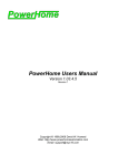
The Zone View screen, which is considered the “main menu” of mControl, provides a summary of all
the defined zones and all devices within a selected zone. From this screen, you can access all of your
Zones and Devices.
Zones Area
Devices Area
Access to
mControl
Settings
Zones Area
This area provides a list of all the user-defined Zones. Each Zone can hold 0 or more Devices.
Zones naming is very flexible – a zone can represent:
Actual rooms in house – for example, “Home Theater”
A functional area of house – for example “Main Floor”
A generic container name – for example “My Macros”
The “active” zone, or the one currently selected, is denoted by a highlighted yellow radio button. To
select a new active room, cursor to it and press OK.
If there are more than 4 zones, it is possible to scroll through them by moving the cursor to the
zones area and pressing either UP/DOWN or PAGE UP/PAGE DOWN.
Page 19
mControl v1 (Home Edition) User Manual
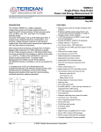
Devices Area
This area provides a list of all the devices for the “active” room. Each device will have:
An icon or image
A status area – this area represents the current status of the device and is updated in realtime.
The device name
Function buttons (e.g., ON, OFF, DIM, BRIGHT, SHOW, PLAY, etc.)
Commands are issued to the device by cursoring to the function and pressing OK. For example, to
turn a light on, cursor to the OFF button (denoted by O) and press OK.
Function Button
Operation
Supported With
Turn ON device
- INSTEON 2456D3 - LampLinc V2 3-Pin
- INSTEON 2456S3 - ApplianceLinc V2 3-Pin
- INSTEON 2476D - SwitchLinc V2 Dimmer
- INSTEON 2476S - SwitchLinc V2 Relay
- X10 AM466 – Appliance module
- X10 LM14A – 2-Way Lamp Module
- X10 LM15 – Screw-in Lamp Module
- X10 LM465 – Lamp module
- X10 PAM21 – 2-Way, 2-Pin Appliance Module
- X10 RSC15 - Remote Controlled Chime
- X10 SSR227 – Super Socket Wall Outlet
- X10 W467 - Dimmable Wall Switch
Turn OFF device
DIM device 25%
BRIGHTEN device
25%
Execute Manual
Macro’s Action List
View Camera
Page 20
- INSTEON 2456D3 - LampLinc V2 3-Pin
- INSTEON 2476D - SwitchLinc V2 Dimmer
- X10 LM14A – 2-Way Lamp Module
- X10 LM465 – Lamp module
- X10 W467 - Dimmable Wall Switch
Manual Macro
- D-Link cameras
mControl v1 (Home Edition) User Manual
Status Image
Meaning
Device is OFF
Device is ON at 100% value
Device is ON at 50% value
Device is ON at nominally 0% value
Other increments are available, depending on the granularity of dim/bright selected for the
device.
If there are more than 4 devices, it is possible to scroll through them by moving the cursor to the
devices area and pressing either UP/DOWN or PAGE UP/PAGE DOWN.
Access to mControl Settings
The “Settings” button provides access to the configuration section of mControl.
Page 21
mControl v1 (Home Edition) User Manual
Settings Screen
The Settings screen provides information about mControl and access to the various mControl
configuration screens.
Settings
Options
Configuration
Options
mControl
Information
Settings Options
The Settings Options buttons provide the following functions:
Home – goes back to the Zone View Screen
Manage Zones – allows configuration of the defined zones and associated devices
Automation – allows modification of existing macros or creation of macros
Camera – allows configuration of cameras
IR Control – allows configuration of IR functionality
Configuration Options
Configuration settings like mControl skins and location information (for sunrise/sunset calculations).
Page 22
mControl v1 (Home Edition) User Manual
mControl Information
This section provides the following information on mControl:
mControl copyright and license information
o
If the license is a 30-day trial license, the “Licensed to” field will be “Embedded
Automation”
o
If the license has been purchased, but not activated, the “Licensed to” field will be
the purchaser’s name, with a parenthetic reference that activation is required
o
If the license has been purchased and activated, the “Licensed to” field will be the
purchaser’s name
mControl version, build number and date of build information
Page 23
mControl v1 (Home Edition) User Manual
Configuration Screen
The Configuration Screen allows modifying the personal configuration settings of mControl.
Configuration
Options
Configuration
Settings
Configuration Options
The Configuration Options buttons provide the following functions:
Back – goes back to the Settings Screen
Home – goes back to the Zone View Screen
Save Changes – saves the configuration changes and returns to the Settings screen
Page 24
mControl v1 (Home Edition) User Manual
Configuration Settings (Main)
This section provides the following configuration options:
Style – the user interface style (or “skin”)
Styles
Blue – Static
Blue – Dynamic
Comments
Default style - recommended for Media Center use.
Provides animated images based on blue background.
If you are using Media Center, please be aware that animated
graphics may cause performance issues because of Media
Center’s scaling and rendering algorithms.
If the style is changed, please empty Temporary Internet Files in Internet Explorer to
ensure the previous style is removed from the cache.
Language – the language used within mControl. Currently only English is supported.
Page 25
mControl v1 (Home Edition) User Manual
Configuration Settings (Location)
This section allows users to define their location. Location information is used to calculate sunrise
and sunset values.
Latitude – in Degrees and Minutes
North or South of Equator – the current location’s relative position to the Equator
Longitude – in Degrees and Minutes
East or West of Greenwich– the current location’s relative position to Greenwich
To determine the Latitude and Longitude
http://www.bcca.org/misc/qiblih/latlong.html.
of
your
location,
we
recommend:
This information is used to calculate sunrise and sunset times for your location. The sunrise and
sunset times can be used as triggers for mControl macros (see section “Macro Configuration –
Time”).
mControl uses the Civil (-6° from the horizon) parameters to arrive at sunrise and sunset times,
based on the enter location.
Page 26
mControl v1 (Home Edition) User Manual
Manage Zones Screen
The Manage Zones Screen provides a summary of all the defined zones and allows changing the order
for display in the Zone View page.
Manage
Zone
Options
Zone
Configuration
Manage Zone Options
The Manage Zone Options buttons provide the following functions:
Back – goes back to the Settings Screen
Home – goes back to the Zone View Screen
Save – saves the current display order of the zones
Add Zone – create a new zone
Page 27
mControl v1 (Home Edition) User Manual
Zone Configuration
This section provides the following options:
Zone Edit – by cursoring to a zone name and pressing OK, access to the Edit Zone
Screen is provided
Zone Display Order – by pressing on the UP/DOWN buttons, the display order of the
zones for the Zone View Screen is modified
Page 28
mControl v1 (Home Edition) User Manual
Add Zone Screen
The Add Zone Screen allows the creation and naming of a new zone.
Add
Zone
Options
Zone
Name
Add Zone Options
The Add Zone buttons provide the following functions:
Back – goes back to the Settings Screen
Home – goes back to the Zone View Screen
Save – saves the new zone
Zone Name
This section provides the following configuration options:
Name – the name of the Zone (Text entry, up to 16 characters)
Page 29
mControl v1 (Home Edition) User Manual
Edit Zone Screen
The Edit Zone Screen allows modifying the configuration of an existing zone.
Edit
Zone
Options
Zone
Configuration
Edit Zone Options
The Edit Zone Options buttons provide the following functions:
Back – goes back to the Manage Zones Screen
Home – goes back to the Zone View Screen
Save – saves the changes for the current zone and returns to the Manage Zones Screen
Add Device – adds a device to the current zone; goes to the Edit Device Screen
Delete Zone – deletes the current zone and returns to the Manage Zones Screen. A Zone
can not be deleted if is associated with a Macro or Actions.
Page 30
mControl v1 (Home Edition) User Manual
Zone Configuration
This section provides the following configuration options:
Name – the name of the zone (Text entry, up to 16 characters)
Device Edit – by cursoring to a device name and pressing OK, access to the Edit Device
Screen is provided
Device Display Order – by pressing on the UP/DOWN buttons, the display order of the
devices for the Zone View Screen is modified
Page 31
mControl v1 (Home Edition) User Manual
Edit Device Screen
The Edit Device Screen allows modifying the configuration of an existing or new device.
Edit
Device
Options
Device
Configuration
Menu
Device
Settings
Edit Device Options
The Edit Device Options buttons provide the following functions:
Back – goes back to the Edit Zone Screen
Home – goes back to the Zone View Screen
Save Changes – saves the changes for the current device and returns to the Edit Zone
Screen
Delete Device – deletes the current device and returns to the Edit Zone Screen. A Device
can not be deleted if it is associated with an Action within a Macro.
Page 32
mControl v1 (Home Edition) User Manual
Device Configuration Menu
Use this menu system to access the various configuration settings for a device:
Main – Define the address, adapter and image for the device
Advanced – Set the update and dim/bright level for the device
Device Settings (Main)
This section provides the following configuration options:
Name – the name of the device (Text entry, up to 16 characters)
Adapter – the adapter used to communicate with this specific device, supported adapters
include:
Adapter
Protocol
Interface
2414U PowerLinc
INSTEON
USB
CM11A
X10
Serial
Use this selection for CM11U
and CM12U operation
CM15A
X10
USB
Also known as ActiveHome Pro
CM17A
X10
Serial
Also known as Firecracker
Page 33
Comments
mControl v1 (Home Edition) User Manual
Port – the serial communication port to use. Valid ports are COM1, COM2, COM3 and
COM4. This option is only available for serial adapters.
Module – The INSTEON or X10 module used to control this specific device. The following
modules are provided on the list:
Module
Protocol
Description
2456Dx
INSTEON
LampLinc V2 Dimmer
2456S3
INSTEON
ApplianceLinc V2 Switch 3-pin
2476D
INSTEON
SwitchLinc V2 Dimmer
2476S
INSTEON
SwitchLinc V2 Relay
AM466
X10
Appliance Module
LM14A
X10
2-way Lamp Module
LM15A
X10
SocketRocket Screw-In Lamp Module
LM465
X10
Lamp Module
PAM21
X10
2-way Appliance Module
RSC15
X10
Chime Module
SR227
X10
Super Socket Module
WS467
X10
Wall Switch Module
If you do not see the module you’d like to control on this list, you can try to choose a module that
most closely resembles your module. For example, if the module you are using is an "appliance" type
of module, you may try to control it by setting the device to be an "AM466" module. For additional
assistance, please email [email protected]
All INSTEON devices added to mControl zones will automatically be added to the 2414U
PowerLinc’s PLC Database, thereby allowing the PowerLinc to recognize the device during 2-way
communications. If the device is deleted from the mControl zone, it will be automatically removed
from the PowerLinc’s PLC Database. This eliminates the need for the user to do manual linking and
unlinking.
Page 34
mControl v1 (Home Edition) User Manual
Address – If you have selected an INSTEON module, you will required to provide an
INSTEON address. The INSTEON address is in the form of xx.xx.xx, where xx is a
number in the range of 0x00 to 0xFF. To find this address, check on the back of your
INSTEON device.
House – If you have selected an X10 module, you will be required to provide an X10
House Address (Spinner entry, Valid Settings: A through P)
o
For convenience, mControl remembers the last House address provided
Unit – If you have selected an X10 module, you will be required to provide an X10 Unit
Address (Spinner entry, Valid Settings: 1 through 16)
Image – User-selectable image for the device (Spinner entry, various images)
Device Settings (Advanced)
This section provides the following configuration options:
Notify – This feature will be available in future versions of mControl.
Granularity – Defines the granularity of each Dim/Bright command. For example, if you
set this to 10%, the brightness levels available will be 10%, 20%, 30%, etc. Of course, this
is dependent on each device’s capability.
Page 35
mControl v1 (Home Edition) User Manual
Automation Screen
The Automation Screen allows modifying the configuration of existing or new macros.
Automation
Options
Macro
List
Automation Options
The Automation Options buttons provide the following functions:
Back – goes back to the Settings Screen
Home – goes back to the Zone View Screen
Save – save the changes in the Macro ordering and return to Settings Screen
Add Macro – allows a creation of a new macro on the Add a Macro page
Page 36
mControl v1 (Home Edition) User Manual
Macro List
This section provides the following configuration options:
Macro Enable – by pressing on this checkbox, the Macro is enabled (with checkmark) or
disabled (without checkmark)
Macro Edit – by cursoring to a macro name and pressing OK, access to the Edit Actions
Screen is provided
Macro Display Order – by pressing on the UP/DOWN buttons, the display order of the
devices for the Macros modified
Page 37
mControl v1 (Home Edition) User Manual
Add Macro Screen
The Add Macro Screen allows for the creation of a new macro.
Add Macro
Options
Macro
Configuration
Menu
Add Macro Options
The Add Macro Options buttons provide the following functions:
Back – goes back to the Automation Screen
Home – goes back to the Zone View Screen
Save – saves the changes for the current macro and returns to the Automation Screen
Page 38
mControl v1 (Home Edition) User Manual
Macro Configuration Menu
Use this menu system to access the various configuration settings for a macro:
Main – Define the name, zone and display status of the macro
Device – Define the device triggers for this macro
Time – Define time triggers for this macro
Schedule – Define the days for which the macro is valid
Macro Configuration (Main)
Name
Setting
Zone
Setting
Display
Setting
This section provides the following configuration options:
Name – the name of the macro (Text entry, up to 16 characters)
Zone – the zone in which the macro will show up in the Zone View screen
Display in Zone – enable display of the macro in the selected zone
Page 39
mControl v1 (Home Edition) User Manual
Macro Configuration (Device)
This section allows you to define a device trigger for the macro. This type of macro trigger is useful
if you would like an INSTEON or X10 remote control to initiate a set of actions.
Enable
Device
Trigger
Device
Trigger
Settings
This section provides the following configuration options:
Enable – Checking this option enables device triggering for this macro
Device Trigger Settings – Define the device and it’s status change to be used as the
trigger for this macro
Page 40
mControl v1 (Home Edition) User Manual
Macro Configuration (Time)
This section allows you to define a time trigger for the macro. This type of macro trigger is useful if
you would like to initiate a set of actions at a given time.
Enable
Time
Trigger
Time
Trigger
Settings
This section provides the following configuration options:
Enable – Checking this option enables time triggering for this macro
Triggered By – Define the time for this macro to initiate.
Triggered By Options
Specific Time
Sunrise and Sunset
Comments
Start the macro based on a specific time of day
Start the macro based on calculated sunrise/sunset for
each day. An offset from the sunrise/sunset can be
selected to trigger the macro earlier or later than
sunrise/sunset. The calculation for sunrise/sunset is
performed using location settings in the configuration
area of mControl.
The calculated time including offset will be shown
underneath the settings buttons.
Page 41
mControl v1 (Home Edition) User Manual
Macro Configuration (Schedule)
This section allows you to define the days on which the macro will be executed.
Schedule
Settings
This section provides the following configuration options:
Schedule – Select the days which the macro will be executed
Page 42
mControl v1 (Home Edition) User Manual
Edit Macro Screen
The Edit Macro Screen allows editing of an existing macro.
Edit Macro
Options
Add Macro Options
The Add Macro Options buttons provide the following functions:
Back – goes back to the Automation Screen
Home – goes back to the Zone View Screen
Save – saves the changes for the current macro and returns to the Automation Screen
Delete – delete the macro
Page 43
mControl v1 (Home Edition) User Manual
Action List Screen
The Action List Screen allows modifying the actions associated with an existing macro.
Action List
Options
Action List
Settings
Action List Options
The Action List Options buttons provide the following functions:
Back – goes back to the Edit a Macro Screen
Home – goes back to the Zone View Screen
Save – saves the current action list configuration for the macro
Add Action – create a new action; goes to Edit Action Screen
Edit Macro – allow editing of the name and trigger type of the macro; goes to the Edit
Macro Screen
Page 44
mControl v1 (Home Edition) User Manual
Action List Settings
This section provides the following options:
Enable/Disable Action – by checking (enabling) or un-checking (disabling) the action will
determine if this action is executed if the macro is run
Action Edit – by cursoring to a action name and pressing OK, access to the Edit Action
Screen is provided
Action Execution Order – by pressing on the UP/DOWN buttons, the execution order of
the action within the macro is modified
Page 45
mControl v1 (Home Edition) User Manual
Edit an Action Screen
The Edit an Action Screen allows modifying actions.
Edit an
Action
Options
Action
Settings
Edit an Action Options
The Edit an Action Options buttons provide the following functions:
Back – goes back to the Action List Screen
Home – goes back to the Zone View Screen
Save – saves the changes for the current action and returns to the Action List Screen
Delete Action – deletes the current action and returns to the Action List Screen
Page 46
mControl v1 (Home Edition) User Manual
Action Settings
This section provides the following configuration options:
Action Type – the type of action to execute. Action types include:
o
o
o
Device – perform a specific device command; for example, turn “Porch Lights” in
the “Backyard” ON. Select a device command by defining the following
parameters:
Zone – the zone in which the device is in
Device – the device to command
Function – the function to be performed by the device
Delay – perform a delay in the macro. A delay is defined by the following
parameters:
Hours – number of hours to delay
Minutes (in 5 minute increments) – number of minutes to delay
IR – send an IR command. The required parameters are:
IR Command – the IR command that will be sent as part of this action.
This command was “Learned” or entered by cutting and pasting raw CCF
text in the IR Command section of mControl
IR Device – the device (or “port”) from which the IR command is to be
sent from. For the case of Global Caché ports, please refer to your
Global Caché user manuals.
Page 47
mControl v1 (Home Edition) User Manual
Camera Screen
The Camera Screen allows modifying the configuration of existing or new cameras.
Camera
Options
Camera
List
Automation Options
The Automation Options buttons provide the following functions:
Back – goes back to the Settings Screen
Home – goes back to the Zone View Screen
Add Camera – allows a configuration of a new camera
Camera List
This section provides the following configuration options:
Edit Camera – by cursoring to a camera name and pressing OK, access to the Edit
Camera Screen is provided
Page 48
mControl v1 (Home Edition) User Manual
Add Camera and Edit Camera Screens
The Add Camera and Edit Camera screens allow for the configuration of a camera.
Edit
Camera
Options
Camera
Settings
Edit Camera Options
The Edit an Action Options buttons provide the following functions:
Back – goes back to the Camera Screen
Home – goes back to the Zone View Screen
Save – saves the changes for the current action and returns to the Camera Screen
Delete Camera – deletes the camera and returns to the Camera Screen
Page 49
mControl v1 (Home Edition) User Manual
Camera Settings
This section provides the following configuration options:
Name – the name of the camera (Text entry, up to 16 characters)
Zone – the location of the camera
Camera – the camera type (refer to the list provided in Supported Hardware)
IP Address – the IP address of the camera
Port Address – the http port used by mControl to talk with the camera (usually 80)
Username – username for login
Password – password for login
Page 50
mControl v1 (Home Edition) User Manual
IR Control Screen
The IR Control screen allows modifying the configuration of IR functionality.
IR Control
Options
IR Control
Configuration
IR Control Options
The Automation Options buttons provide the following functions:
Back – goes back to the Settings Screen
Home – goes back to the Zone View Screen
IR Control Configuration
This section provides the following configuration options:
Commands – add, modify and delete IR commands
Adapters – view available adapter ports. These correspond to the available Global Caché
ports available.
Page 51
mControl v1 (Home Edition) User Manual
Adapters Ports
View the IR ports available for sending commands to.
Adapter
Ports
Adapter Ports
When you select the Adapters tab, this screen provides a list of all the available adapter ports.
These ports are used to send and receive IR commands. Use one of these ports in macro actions
to define the destination location of the IR command.
mControl currently only display the ports, as configured within the Global Cache adapter – you can
not edit, delete or add ports. For more information on Adapter Ports, please refer to your Global
Caché user manual.
Page 52
mControl v1 (Home Edition) User Manual
IR Commands
Shows a list of all IR commands and allows creation of new IR commands.
IR Control
Options
IR
Commands
IR Command Options
The Automation Options buttons provide the following functions:
Back – goes back to the Settings Screen
Home – goes back to the Zone View Screen
Add IR Command – allows creation of a new IR command
IR Commands
This section shows the list of IR commands available for macros.
Page 53
mControl v1 (Home Edition) User Manual
Advanced mControl Functionality
Using Macros
Device Triggered Macros
Use “Device” triggered macros when you need respond to a status change of a particular device.
For example, if a motion detector goes off, you may want to turn on a set of lights for 5 minutes and
sound a chime.
1. Create the Macro
a. Navigate to the “Settings” page
b. Select the “Automation” option
c. Select the “Add Macro” option
d. Select the “Main” tab and enter the information required to create the macro,
including:
Name – the name of the macro
Zone – the zone to assign the macro within
Display – to enable the display of the macro within the zone
Page 54
mControl v1 (Home Edition) User Manual
2. Define the “Device” trigger, which is the event which will start the macro, by navigating to
the “Device” tab and then entering the information required, including:
Enable – enables the device trigger capability
Device Zone – the zone in which the triggering device is located
Device – the triggering device (e.g., the motion detector)
Command – the change to look for to trigger the device
3. Add an action to take, by selecting the “Add Action” option.
Page 55
mControl v1 (Home Edition) User Manual
4. Select the action type to take, either Device or Delay.
Device – select a device, by selecting the zone in which the device is defined and
the device name, and a command to send to the device.
Delay – select the amount of time to delay (hours, minutes and seconds).
5. Continue steps 3 and 4 until you have defined all the actions required.
The following sample shows a set of actions to take upon receipt of a motion detector
going off. In this sample, the “Backyard lights” come on, an “Intruder chime” is sounded
and after 5 minutes, the “Backyard lights” are turned off.
Page 56
mControl v1 (Home Edition) User Manual
Time Triggered Macros
Use “Time” triggered macros when you need perform home automation functions at a particular
time. For example, you may want to turn on lights at 7:00pm and then turn them off at 11:00pm.
1. Create the Macro
a. Navigate to the “Settings” page
b. Select the “Automation” option
c. Select the “Add Macro” option
d. Select the “Main” tab and enter the information required to create the macro,
including:
Name – the name of the macro
Zone – the zone to assign the macro within
Display – to enable the display of the macro within the zone
Page 57
mControl v1 (Home Edition) User Manual
2. Define the “Time” trigger, which is the time which will start the macro, by navigating to the
“Time” tab and then entering the information required, including:
Enable – enables the time trigger capability
Hour/Minute – the time when the trigger should happen
3. Add an action to take, by selecting the “Add Action” option.
Page 58
mControl v1 (Home Edition) User Manual
4. Select the action type to take, either Device or Delay.
Device – select a device, by selecting the zone in which the device is defined and
the device name, and a command to send to the device.
Delay – select the amount of time to delay (hours, minutes and seconds).
5. Continue steps 3 and 4 until you have defined all the actions required.
The following sample shows a set of actions to take upon the time becoming 7:00pm. The
“Main Entry” light is turned on and after 4 hours, it is turned off.
Page 59
mControl v1 (Home Edition) User Manual
Setting up a Camera
1. Follow the instructions provided with your D-Link camera to complete the hardware set-up,
including establishing the wired or wireless network and connecting power.
2. Use the D-Link software’s IP Installer option to find the available cameras. Click on the “Link”
button to configure for mControl. Please note the IP Address here for future use –
mControl requires this information.
Page 60
mControl v1 (Home Edition) User Manual
3. Once linked, select the “Configuration” option of the camera.
Once you enter this screen, the D-Link software automatically loads a MPEG4 ActiveX
component which allows you to view the camera. This procedure must be followed to
load the ActiveX object on each client machine you wish to view the camera.
4. Navigate to the “Advanced” tab, then select the “Network” option. For the HTTP Port enter
“29990” (as shown in the below graphic).
Once you do this, you can only access the camera by specifying this port number. For
example, on Internet Explorer, you would enter http://<camera IP address>:29990/
Page 61
mControl v1 (Home Edition) User Manual
5. Navigate to the “Tools” tab, then select the “Admin” option. For security reasons, you may
create an mControl user by assigning a Username/Password. Please note the
Username/Password here for future use – mControl requires this information.
6. Once completed, you will either have to re-power (or reset) your camera.
Page 62
mControl v1 (Home Edition) User Manual
7. Now you are ready to add the camera to mControl software.
a. Navigate to the “Settings” page
b. Select the “Camera” option
c. Select the “Add Camera” option
d. Enter the information required to connect to the camera, including:
Name – the name of the camera (for example, “Back Porch”)
Zone – the zone that the camera should be displayed within
Model – the camera model
IP Address – as per step #2 of this process, enter the IP address
Port – mControl requires this to be set to 80
Username – as per step #5, enter the Username
Password – as per step #5, enter the Password
e. “Save Changes” and return
8. View the camera from the “Zone View” screen
Page 63
mControl v1 (Home Edition) User Manual
9. Navigate to the “Play” button on the camera device. If you press OK, a full-screen will be
displayed.
Page 64
mControl v1 (Home Edition) User Manual
Configuring and Using a Global Caché IR System
1. Follow the instructions provided with your Global Caché Network IR Adapter to complete the
hardware set-up, including establishing the wired or wireless network and connecting power.
2. Connect to the GC-100 Network Adapter using the default IP address and configure the IP
Address, Network Mask and Gateway Address to be compatible for your network.
Network
Settings
Page 65
mControl v1 (Home Edition) User Manual
You may also want to configure the Port settings for each of the ports available on the GC-100
Network Adapter – mControl use these settings to send and receive IR commands.
3. Enable and configure the GC-100 Network Adapter within mControl, by editing the
configuration settings in the “mServer.exe.xml” located in the C:\Program Files\Embedded
Automation\mControl\server directory.
Open the “mServer.exe.xml” file using Notepad or equivalent text editor, find the section which
has configuration settings for the GC-100 Network Adapter and make the following changes:
Load the GC-100 Network Adapter driver into mControl – ensure that the load
parameter for the adapter is “Y” (see underlined section below).
Provide the proper IP Address for the GC-100 Network Adapter – ensure the
value of the IP parameter matches the IP Address entered during step #2 (see
underlined section below).
<adapter base="GC100" load="Y" assembly="GC100.dll"
driver="EmbeddedAutomation.mServer.Adapters.GC100Manager">
<aparam name="DISPLAY-AS" value="GC-100"/>
<aparam name="OTHER-NAMES" value="GC-100-12|GC-100-18"/>
<aparam name="DESCRIPTION" value="GlobalCache Network Adapter"/>
<aparam name="SUPPORTS" value="GC100"/>
<aparam name="APROTOCOL" value="GC100"/>
<aparam name="PORTS" value="4998"/>
<aparam name="ip" value="192.168.100.71"/>
</adapter>
To enable any changes in adapter XML settings, you must restart the mControl Automation
Service, which during initialization reads the XML files.
Page 66
mControl v1 (Home Edition) User Manual
4. Navigate to the IR Control section and learn an IR command.
From the Settings page, select IR Control. From the IR Control page, select the “Commands”
tab. Select the “Add IR Command” button to add a new IR command.
On the Add IR Command page, type the name of the IR command, say “TV On”. There are
two ways to enter the IR command:
a. If you have a GC-IRL (Globale Cache IR Learner adapter connected to the GC-100
Network Adapter), you can learn the IR command. To do this, press the “Learn”
button and within a 5 second time enter the command by pressing the remote control
button while pointing at the GC-IRL. The command which is seen by the GC-IRL will
appear in the text box in CCF format as shown in the diagram below.
For more information on CCF formats, please refer to:
http://www.geocities.com/jpollock_2000/ccf.htm
mControl only supports IR commands less than 900 characters.
Page 67
mControl v1 (Home Edition) User Manual
b. If you have access to CCF (Component Control File) codes for the command, it is
possible to cut and paste them directly into the text box area.
To get to CCF codes for your component, we recommend
http://www.remotecentral.com/
To convert binary CCF files to text format, we recommend utilities like the CCF
Tools utility (also found on http://www.remotecentral.com/).
For more information on CCF formats, please refer to:
http://www.geocities.com/jpollock_2000/ccf.htm
mControl only supports IR commands less than 900 characters.
Page 68
mControl v1 (Home Edition) User Manual
5. Use IR commands within mControl Macros, to control electronic components.
Within any macro, add an action of type “IR”, selecting the specific command IR command
saved as part of the step 4.
IR Commands and Windows XP Media Center Edition 2005
A reference of Windows XP Media Center Edition 2005 CCF commands can be found here:
http://www.remotecentral.com/cgi-bin/files/rcfiles.cgi?kw=media+center&fc=-&area=pronto&db=&br=&dv=&dt=&so=
Please note, Windows XP Media Center Edition 2005 utilizes a two-code IR command toggle
system to eliminate “bounce” or double keying. The debounce setting of Media Center can be
disabled, thereby allowing a single command to represent the IR command. For a good reference
on this topic, see: http://blogs.msdn.com/mswanson/archive/2004/12/01/272766.aspx.
Page 69
mControl v1 (Home Edition) User Manual
Configuring mControl Clients
Using mControl from a remote PC using Internet Explorer
1. Start Internet Explorer and enter the following in the address area: http://<mControl
PC>:29990/default.aspx, where “<mControl PC>” is the name or IP address of the PC on
which mControl was installed on.
Adding mControl to a remote Windows XP Media Center Edition PC
Please note, this is an unsupported feature of mControl and once implemented, requires manual
editing of your Windows registry – the mControl uninstaller does not remove these settings. We
recommend making a back-up of your Windows registry before any substantive changes.
1. Copy the mControl.mcl file located in the “C:\Program
Files\Embedded
Automation\mControl” directory to the new client machine’s “C:\Documents and
Settings\<user of your choice>\Start Menu\Programs\Accessories\Media
Center\Media Center Programs” directory.
2. Edit the file using Notepad to modify the URL, replacing 'localhost' with the name of the new
client machine. For example, if your mControl Automation Service machine is called
'MyServer, you would change the URL setting to "http://MyServer:29990/Default.aspx".
3. Once the file has been modified, you will be able to access it from the “More Programs” area of
the client machine.
Page 70
mControl v1 (Home Edition) User Manual
Adding mControl to the Start Menu of a Windows XP Media Center Edition PC
Please note, this is an unsupported feature of mControl and once implemented, requires manual
editing of your Windows registry – the mControl uninstaller does not remove these settings. We
recommend making a back-up of your Windows registry before any substantive changes.
To use this function on a remote PC, first perform the step above to “Add mControl to a Remove
Windows XP Media Center Edition PC”.
Only a maximum of two 3rd party items can be added to the “Start Menu” – so if two 3rd party
items are already installed on the “Start Menu”, the following steps will have no effect.
1. Using Notepad or equivalent text editor, copy the following into a file called mControl.reg:
Windows Registry Editor Version 5.00
[HKEY_LOCAL_MACHINE\Software\Microsoft\Windows\CurrentVersion\Media
Center\Extensibility\Categories\Start Menu\{3de6904a-d9c7-4ef9-b77dc1216b39161f}]
"AppID"=" {aebf238a-a1c5-4354-ba23-e693cb9f219c}"
"TimeStamp"=dword:0add6130
"Title"="mControl"
"URL"="http://localhost:29990/Default.aspx"
2. After saving the file, double-click on the file or, within Explorer, perform a right-click and select
the “Merge” option. You will be asked if you want to add the information to the Windows
registry. Once you agree, the registry settings will be added and mControl will be available on
the “Start Menu” when Media Center is re-started.
Page 71
mControl v1 (Home Edition) User Manual
Configuring mControl
mControl allows configuration of User and System settings within XML files. Please ensure all
changes comply with XML - improper XML may affect the operation of mControl.
To enable any custom settings, you must restart the mControl Automation Service, which during
initialization reads the XML files. Please make a back-up of any XML file before making changes.
Custom User Settings
Custom user settings can be made in the “mControlDataSet.xml” file, located in the “C:\Program
Files\Embedded Automation\mControl” directory.
Adding Custom Images
Add a <device-image> element to the XML data.
Images of type PNG, GIF, and JPEG are preferred. Image size should be 120 by 120 pixels
for best display – other sizes will be scaled up/down to fit and may appear distorted.
A blank image, called “Blank.gif” is provided in the “C:\Program Files\Embedded
Automation\mControl\images\device” directory. You may use this image as a template for
creating a custom device image.
In this sample, a “Chime” device, which uses the “Chime.gif” image has been added (shown in
red).
<images>
<device-image>
<image-name>Chime</image-name>
<image-file>Chime.gif</image-file>
</device-image>
<device-image>
<image-name>Lamp</image-name>
<image-file>Lights.gif</image-file>
</device-image>
</images>
Page 72
mControl v1 (Home Edition) User Manual
Adding Custom DIM Granularity Values
Under the <configuration> element within the XML file is the <dimvalues> element, which defines
the DIM granularity values.
In the following sample, a 33% DIM granularity has been added (as shown in red).
<configuration>
<time-offset>-60|-45|-30|-20|-15|-10|5|+0|+5|+10|+15|+20|+30|+45|+60</time-offset>
<dimvalues>10|20|25|33|50|75</dimvalues>
<delay-hours>0|1|2|3|4|5|6|8|10|12|24</delay-hours>
<delay-minutes>00|01|02|03|04|05|10|15|20|30|45</delay-minutes>
<delay-seconds>00|01|02|03|04|05|10|15|20|25|30|40|50</delayseconds>
</configuration>
System Configuration Settings
System configuration settings can be made in the “mServer.exe.xml” file, located in the
“C:\Program Files\Embedded Automation\mControl\server” directory.
Page 73
mControl v1 (Home Edition) User Manual
Version History
v1.31 – released December 2005
Issue #
317,341,350,
354, 356
158,336,348
323,355
205,206,225,
299,302,313,
329,340,343,
345,347,351,
360,361,366,
367,368,372,
373,377,380
Description
Improved robustness for installation, logging and copy protection, including:
Installation in non-default directory or drive
Size and number of log files can be set
Proper version is shown in “More Programs” area of MCE
Automatic upgrading of v1.1x database adds necessary fields
Improved robustness for editing of mControl devices, zones and related data.
Improved robustness for Macro handling, including:
Will not allow selection of undefined addresses as triggers
Improved robustness related to INSTEON and X10 support, including:
Elimination of spurious exception errors
Improved automatic handling of plugging and unplugging of CM15A and
2414U
Behavior for INSTEON devices changed to reflect expected behavior
instead of X10 behavior
Multiple X10 ON commands handling
Devices, if linked in mControl/2414U, will update status if ControLinc,
SwitchLinc or KeypadLinc also have them linked and change status
Incoming and outgoing X10 messages on 2414U INSTEON adapter
Improved robustness for automatic linking and unlinking of devices in
PowerLinc’s database
v1.30 – released November 2005
Issue #
238
33 ,221,228,
235,236,268,
269,274,275,
280,297,307,
311,322
100,169,259,
277,278,296,
312,321
90,193,203,
242,243,261,
265,266,267,
270,276,282,
287,300, 306
Description
Confirmed support of Windows XP Media Center Edition 2005 Rollup 2
Enhanced Macro support, including:
Support for sunrise and sunset macro triggers. Configuration allows for
entry of longitude and latitude, thereby allowing mControl to calculate the
sunrise and sunset for the day. Offsets can be added to control desired
trigger points relative to sunrise and sunset.
Greater than 6 hours for delays
Enhanced error checking for incorrect macro triggers and actions
Added support for IR functionality, including:
Support for the Global Caché Network IR Adapter, including “learning”
functionality (using GC-IRL module)
Support for raw Component Control Files (CCF), thereby allowing manual
entry, using cut and paste, of known IR commands
Enhanced configurability, including:
Selectable styles (or “skins”). Default style is now non-animated Blue, to
ensure optimum performance for MCE environments.
Expanded XML configuration files and related documentation. Please refer
to the “Configuring mControl” section of the mControl User Manual
Page 74
mControl v1 (Home Edition) User Manual
v1.30 – released November 2005 (continued)
Issue #
94 ,133,139,
164,199,222,
236,240,262,
275, 280,295
218,225,241,
243,249,308,
309, 310,315,
318, 319,328,
331
130,177,200,
212,231,232,
233,239
168,195,214,
216, 242
Description
Performance improvements, including:
mControl no longer throws an exception if stopped or restarted
Memory management is no longer affected by presence or absence of
internet connection
Performance of the mControl client, when used in conjunction with Shared
View Port (SVP) is greatly improved
Improved entry field validation throughout
Enhanced support of the INSTEON protocol, including:
Added automatic linking and unlinking of INSTEON devices. All devices
added to mControl zones will automatically be added to the 2414U
PowerLinc’s memory, thereby allowing the PowerLinc to recognize the
device during 2-way communications. If the device is deleted from
mControl, it will be automatically removed from the PowerLinc’s memory.
This eliminates the need for the user to do manual linking and unlinking.
Added X10 to INSTEON command translator. Entries in the
mServer.exe.xml configuration file will allow incoming X10 signals to be
translated into a specified INSTEON address. This is particularly useful for
cases where hybrid systems exist and rely on a X10-based back-end
controller and INSTEON-based lighting control.
Confirmed support for 2486D (INSTEON KeypadLinc)
Improved incoming X10 event handling
INSTEON Adapter/Device and FAQ sections has been updated
Improvements to the mControl installer, including:
mControl database and license are backed up (.cpy extension)
Improved installation of 3rd party software (e.g., CM15A X10 drivers)
Default install is for “Everyone” to ensure that mControl is visible to MCE
Extenders
DLLs are properly registered and loaded in .NET Global Assembly Cache
Documentation improvements, including:
Provided a section which describes how to remote mControl to another PC
using either Internet Explorer or as a part of the “More Programs” section
of Media Center
Provided a section which describes how to add mControl to the “Start
Menu” of Media Center
Provided a section related to Custom User and System Configuration
Settings.
Provided information on how to use mControl when no active Internet
connection is established.
Page 75
mControl v1 (Home Edition) User Manual
v1.20 – released September 2005
Issue #
13, 67
31
90,131,
179
93,129,
162,187
132,134,
150,153,
158,159
137
170
136,138,
143,145
184,197
Description
User interface will now update, in real-time, any device status changes. These changes
may have been initiated by the user, by another user on a remote client or via macro
actions.
Added support for security cameras. Specifically, the following cameras are now
supported:
D-Link DCS-2100+
D-Link DCS-5300W
An XML file has been created to hold device configuration information. Users may now:
Create custom images for a device, using “blank.gif”
Rename devices (e.g., for localization purposes)
Add/remove devices from the device list
Page Up/Down buttons are now fully implemented and are usable for touch screen
applications.
Macro functionality has been enhanced:
Bright/Dim are available as action commands
Added “day” settings to allow running of a macro on specific days
Timer macros are now stored properly in the mControl database
Macros now reference Zones/Devices properly
Finer granularity on delay action steps
External INSTEON device changes can be used to trigger events.
NOTE: To avoid infinite recursion, please ensure any actions within the macro do not
retrigger the same macro.
Configurable Dim/Bright granularity is supported for each dimmable device.
INSTEON support enhancements, including:
Successive INSTEON commands issued within a macro will now properly
execute. Previously, it was possible that some commands would not be
processed due to the capability of the 2414x adapter.
Remote commands, for example, from a ControLinc or a SwitchLinc are now
recognized by the adapter.
General usability enhancements, including:
Confirmed Windows XP Home Edition support
Installer has been enhanced to allow mControl installation in user selected drive
and directory
User no longer has to uninstall old version and install new version.
v1.11 – released on August 3, 2005
Issue #
135,136
Description
The mControl User Manual, specifically the “Using mControl” section, has been updated
to reflect the changes made for mControl v1 (Home Edition) release
Several enhancements to the INSTEON protocol driver including:
All outgoing commands check if PowerLinc (USB) adapter is connected or
disconnected, and will update the mControl database accordingly
A 2 second timeout (and retry) strategy is included to ensure robust
communications.
Devices within the mControl database will be updated upon receipt of a
corresponding event. Previously, the status change was only recorded if it was
initiated by an mControl INSTEON command
Page 76
mControl v1 (Home Edition) User Manual
v1.10 – released on July 21, 2005
Issue #
10
16, 17
26, 65
29, 71,
82, 83,
88, 99
54, 57
61
77, 78,
106
101
102
103
104
Description
The mControl User Interface Client is now fully supported on browsers based on Internet
Explorer 6.
Validated support for additional X10 adapters, modules, transceivers, remotes and
sensors. In addition to supporting these devices within mControl, the User Manual and
web site have been updated to reflect this support.
To allow easier entry of devices, upon selecting Add Device, mControl will preload the
house and adapter, based on the previous device entered.
Improvements to the mControl User Interface Client including:
Additional device images have been provided.
Improved cursoring and paging within zones with many devices
Improved consistency in screen names and navigation
Consistent location of navigation and add/delete/edit buttons
Ability to enable/disable Macros with single check box
Error screens with recovery suggestions
Increased robustness to CM11A adapter interface. A command retry strategy has been
added to ensure that all commands are sent.
Older versions of mControl database are now automatically converted to latest version.
Managed deletions of Devices and Zones:
A warning is given upon Device Deletion to alert that related Macro Actions may
be affected. If confirmed, all associated Macros Actions are deleted.
A warning is given upon Zone Deletion to alert that underlying Devices and
associated Macros and their Actions may be affected. If confirmed, all
underlying Devices are now marked as deleted and all associated Macros and
their Actions are deleted.
User-selectable logging as defined in “mServer.exe.config” configuration file. The
default setting is ALL.
mControl now supports COM1 through COM4 ports for all serial-based adapters.
Support for INSTEON protocol, specifically the 2414 PowerLinc adapter. mControl
allows sending commands to both INSTEON and X10 modules. In addition, mControl
will process commands received on this adapter. Please refer to the “Supported
Automation” section of this manual for more details.
mControl now supports receiving X10 messages using a CM15A adapter. Received
power line and RF commands can be processed to update the database or launch
Device Macros. Please refer to the “Supported Automation” section of this manual for
more details.
Page 77
mControl v1 (Home Edition) User Manual
v1.00 (Release Candidate 1) – released on June 13, 2005
Issue #
15, 34,
48
40
81, 82,
84, 91,
93
Description
mControl Automation Service now provides user interface screens to mControl User
Interface Client. IIS is no longer required.
Updated software interface for X10 CM15A ActiveHome Interface (USB)
Improvements to mControl User Interface Client including:
User will be prompted for saving edits if Back or Home button are pressed
Current location or function is displayed over mControl watermark
Home button for easy return to Zone View screen
Amalgamation of the Create and Edit buttons
Use of mControl logo throughout
Mouse functionality matches remote control functionality
Page 78
mControl v1 (Home Edition) User Manual
Known Issues
All of the below-mentioned issues will be resolved in future versions of mControl:
Issue #
95
79
69
Description
If the mControl Automation Service is not running the mControl User Interface Client
does not come up on MCE or IE. There is a “Page Not Found” error.
NOTE: Restart mControl Automation Service
It is possible to create non-unique device name and zone name combinations. For
example, it is possible to create two devices with the same name within a zone or
devices with the same address.
NOTE: Please ensure that addresses, device names and zones are unique.
First time entry in to mControl may take >30 seconds.
NOTE: Subsequent entries will be almost immediate.
Page 79
mControl v1 (Home Edition) User Manual
Error Management
The following summarizes mControl error conditions and suggested actions:
Errors
Description
AUTOMATION SERVER IS NOT RUNNING
PAGE NOT FOUND
SERVER IS NOT STARTED YET
Please ensure that the mControl Automation
Service is running. Use Control Panel's
Administrative Tools and select Services.
Within the Services manager, cursor to the
"mHome Automation Server". If this service is
stopped, then right-click to 'Start' or press the
play button on the tool bar.
NO ZONES IN DATABASE
In order to create a macro, there must be a
minimum of one zone in the system. Please
go back and enter a zone before continuing
with the automation controls.
SERIAL PORT TIMEOUT EXCEPTION
Please ensure that the CM11A/CM12U
adapter is connected to your PC.
MACRO NOT READY
MACRO ALREADY LOADED
Macro failed. Please retry or review log files.
MACRO ALREADY RUNNING
Macro failed. An instance of this macro is
already running.
mControl license has expired, is missing or
has been damaged. Please contact
support@embeddedautomation for further
assistance.
PROTECTION FAILED
LICENSE FILE NOT FOUND
VALIDATION OF MODULE FAILED
DEMO LICENSE HAS EXPIRED
LICENSE FILE IS TAMPERED WITH
PROTECTION WRONG TAG
SYSTEM DATE IS TAMPERED WITH
SYSTEM ERROR
mControl has encountered an unknown error,
please restart mControl and try again.
Page 80
mControl v1 (Home Edition) User Manual
Frequently Asked Questions (FAQs)
Installation and Start-up
I receive an "Unable to Display Page" error when I try to start mControl from Windows Media
Center. The message says "Media Center is unable to load the page
http://localhost:29990/Default.aspx."
This is because the mControl Automation Service is not running. Please 'Start' the mControl
Automation Service, by going to the Control Panel's Administrative Tools and selecting Services. Within
the Services manager, cursor to the "mHome Automation Service". Right-click to 'Start' or press the
play button on the tool bar.
Can I use Internet Explorer to run mControl?
Yes, mControl will run on Internet Explorer. To start mControl type http://localhost:29990/ into the
Internet Explorer address area.
How do I access mControl from another Windows XP Media Center Edition 2005 machine?
mControl consists of two parts: (a) mControl Automation Service and (b) mControl User Interface
Client(s). By default, mControl installs both of these on the same machine. Since the mControl
Automation Service supports multiple clients, you can easily add a MCE client(s). (This is particularly
useful if you've installed mControl on a Windows XP Professional machine.)
Simply
copy the mControl.mcl file located in the “C:\Program
Files\Embedded
Automation\mControl” directory to the new client machine’s “C:\Documents and Settings\<user
of your choice>\Start Menu\Programs\Accessories\Media Center\Media Center Programs”
directory. Edit the file using Notepad to modify the URL, replacing 'localhost' with the name of the new
client machine. For example, if your mControl Automation Service machine is called 'MyServer, you
would change the URL setting to "http://MyServer:29990/Default.aspx". Once the file has been
modified, you will be able to access it from the “More Programs” area of the client machine.
I get a "The trial version of mControl has expired" message. What happened?
The mControl software you are using has been provided for limited time use. This is governed by a
form of copy protection. Either one of three things happened to cause the "The trial version of mControl
has expired" message: (a) the 30 days you had to review mControl has passed, (b) the mControl
license has become damaged, or (c) the system date has been changed.
Please note: if your license has expired, all navigation and viewing functionality will still be available;
however, all device control and automation will be disabled.
You can purchase mControl from the Embedded Automation web store.
Page 81
mControl v1 (Home Edition) User Manual
X10 Automation
I don't see the X10 module I would like to control in the module list on the "Edit Device" screen.
You can add, remove or rename devices by making changes to the “mServer.exe.xml” file. Please refer
to the “Configuring Devices” section of the mControl v1 (Home Edition) User Manual.
Can devices controlled by CM11A/CM12U or CM17A X10 adapters be used for "Device" macros
triggers?
Only devices connected to a 2414U INSTEON or CM15A X10 adapters can be used for "Device"
macro triggers.
I plugged in my CM15A X10 Adapter and Windows asked for driver files. I pressed ‘Cancel’ but
now I see unknown devices (denoted by yellow question marks) in Device Manager. What
should I do?
To fix this simply install mControl. mControl will ask to install the required drivers for the CM15A X10
Adapter.
INSTEON Automation
Does mControl work with SwitchLincs?
Currently, mControl can turn on, turn off, dim and brighten SwitchLincs. Even if your SwitchLinc is
"registered", they do not send messages back to mControl and as a result, mControl can not display
any changes made by users. For example, if you dim a SwitchLinc, mControl does not see this change
and hence is not able to update the display on user interface.
We are working with Smarthome/INSTEON to enhance mControl to sense and display SwitchLinc
changes, as made by users.
mControl does not appear to receive device triggers, what could be happening? The 2414U
INSTEON adapter LED blinks On and Off about every 1 second, what could be happening?
The memory in the 2414U INSTEON Adapter’s memory may be “corrupt”. Please email
[email protected] – we can provide a utility to revert the 2414U to factory
conditions.
Page 82
mControl v1 (Home Edition) User Manual
Support
Log Files
Log files contain journalized information of mControl operation, informational messages and errors. Log
files can be found in the following folder: C:\Program Files\Embedded Automation\mControl\logs.
Log files are named mControl<xxx>.log, where <xxx> represents a numeric value. The most
recent log file is mControl000.log. If this log is full, it is renamed to mControl001.log and a new
mControl000.log is opened for use. Up to 10 log files can exists, named incrementally, via this
cascading copying progress.
Contact Us
Send us an email to: [email protected] or go to the Support page at
www.embeddedautomation.com.
Page 83