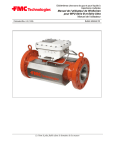
1
Multipath Ultrasonic Gas and Liquid Flow Meters MPU Series B and Ultra Series Winscreen User Manual User Manual Bulletin MN0A001 Issue/Rev. 0.0 (11/09) The Most Trusted Name In Measurement Important All information and technical specifications in this documentation have been carefully checked and compiled by the author. However, we cannot completely exclude the possibility of errors. Smith Meter GmbH is always grateful to be informed of any errors. Page 2 of 70 MN0A001 0.0 (11/09) TABLE OF CONTENTS 1. INTRODUCTION ..................................................................................... 7 1.1. Copyright .......................................................................................... 7 1.2. Trademarks ....................................................................................... 7 1.3. Abbreviations ................................................................................... 8 1.4. Guarantee .......................................................................................... 9 1.5. Equipment Required ...................................................................... 10 2. PRE-OPERATION ................................................................................. 11 2.1. Install Winscreen Software ............................................................ 11 2.2. Uninstall Winscreen Software ....................................................... 11 2.3. Set the IP address on the PC (Ethernet only) .............................. 11 3. START WINSCREEN PROGRAM ........................................................ 12 3.1. Connecting to the Ultrasonic Meter .............................................. 13 3.1.1. First time communication setup ................................................ 13 3.1.2. Establish communication with Ethernet link.............................. 14 3.1.3. Establish communication with serial link................................... 15 3.2. Run Winscreen against PC Simulator .......................................... 15 3.3. Trouble Shooting – Ethernet ......................................................... 16 4. OPERATING THE WINSCREEN PROGRAM ....................................... 17 4.1. Menu Overview ............................................................................... 17 4.2. Measured Values ............................................................................ 18 4.2.1. Alarm indicator (top left) ........................................................... 19 4.2.2. Current Values ......................................................................... 19 4.2.3. Current Path Values ................................................................. 20 4.2.4. Axial Flow Profile ...................................................................... 20 4.2.5. Transversal Flow (only on 6 path meters) ................................ 20 4.2.6. Velocity / VOS History .............................................................. 20 4.3. Trend ............................................................................................... 21 4.4. Database Configuration ................................................................. 23 4.4.1. Contents in the Database Configuration window ...................... 23 4.4.2. Change parameters .................................................................. 25 4.4.3. Save/load the database ............................................................ 26 4.5. Logs ................................................................................................. 27 4.5.1. Active alarm log ........................................................................ 28 4.5.2. Historical alarm log ................................................................... 28 4.5.3. Event log .................................................................................. 29 MN0A001 0.0 (11/09) Page 3 of 70 4.5.4. Operator change log ................................................................. 29 4.6. Database Report ............................................................................. 30 4.6.1. Select Report Format ............................................................... 31 4.6.2. Print Database Report .............................................................. 32 4.6.3. Generate Database Report ...................................................... 33 4.6.4. Save Database Report ............................................................. 34 4.6.5. Exporting Database Report ...................................................... 34 4.6.6. Open Database Report............................................................. 34 5. MPU DIAGNOSTICS SETUP ................................................................ 35 5.1. Introduction .................................................................................... 35 5.2. Velocity of Sound ........................................................................... 35 5.2.1. Description ............................................................................... 35 5.2.2. Setting the limits ....................................................................... 36 5.2.3. Objects ..................................................................................... 36 5.3. Gain ................................................................................................. 37 5.3.1. Description ............................................................................... 37 5.3.2. Setting the limits ....................................................................... 37 5.3.3. Objects ..................................................................................... 37 5.4. Signal % .......................................................................................... 38 5.4.1. Description ............................................................................... 38 5.4.2. Setting the limits ....................................................................... 38 5.4.3. Objects ..................................................................................... 38 5.5. Signal to Noise Ratio ...................................................................... 39 5.5.1. Description ............................................................................... 39 5.5.2. Setting the limits ....................................................................... 39 5.5.3. Objects ..................................................................................... 39 5.6. Profile measurements (only 6 path meter) ................................... 40 5.6.1. Description ............................................................................... 40 5.6.2. Profile flatness .......................................................................... 40 5.6.3. Profile symmetry ....................................................................... 40 5.6.4. Swirl Flow ................................................................................. 41 5.6.5. Cross Flow ............................................................................... 41 5.6.6. Reference profile / Fingerprint .................................................. 41 5.6.7. Setting the limits ....................................................................... 41 5.6.8. Objects ..................................................................................... 42 5.7. Turbulence measurements ............................................................ 43 5.7.1. Description ............................................................................... 43 5.7.2. Setting the limits ....................................................................... 43 5.7.3. Objects ..................................................................................... 43 6. ULTRAX DIAGNOSTICS SETUP .......................................................... 44 6.1. Introduction .................................................................................... 44 6.2. Velocity of Sound (VOS) ................................................................ 44 6.2.1. Description ............................................................................... 44 6.2.2. Setting the limits ....................................................................... 45 Page 4 of 70 MN0A001 0.0 (11/09) 6.2.3. Objects within the Database ..................................................... 45 6.3. Gain ................................................................................................. 46 6.3.1. Description ............................................................................... 46 6.3.2. Setting the limits ....................................................................... 46 6.3.3. Objects in Database ................................................................. 46 6.4. Signal % .......................................................................................... 47 6.4.1. Description ............................................................................... 47 6.4.2. Setting the limits ....................................................................... 47 6.4.3. Objects in Database ................................................................. 47 6.5. Signal to Noise Ratio ...................................................................... 48 6.5.1. Description ............................................................................... 48 6.5.2. Setting the limits ....................................................................... 48 6.5.3. Objects in Database ................................................................. 48 6.6. Profile measurements .................................................................... 49 6.6.1. Description ............................................................................... 49 6.6.2. Profile flatness .......................................................................... 49 6.6.3. Profile symmetry ....................................................................... 49 6.6.4. Swirl Flow ................................................................................. 50 6.6.5. Cross Flow ............................................................................... 50 6.6.6. Reference profile / Fingerprint .................................................. 50 6.6.7. Setting the limits ....................................................................... 51 6.6.8. Objects in Database ................................................................. 51 6.7. Turbulence measurements ............................................................ 52 6.7.1. Description ............................................................................... 52 6.7.2. Setting the limits ....................................................................... 52 6.7.3. Objects in Database ................................................................. 52 7. DIAGNOSTICS AND SERVICE ............................................................ 53 7.1. Analyzer – Transducer Signal Quality Check .............................. 53 7.2. Check signal acquisitions ............................................................. 55 7.3. Check signal processing ............................................................... 56 7.4. Check flow calculations ................................................................. 57 7.5. Check I/O system............................................................................ 58 8. OTHER FEATURES .............................................................................. 59 8.1. SIMULATION ................................................................................... 59 8.2. CHANGE PASSWORD AND SECURITY LEVEL............................ 60 8.2.1. Change Password. ................................................................... 60 8.2.2. Change Security Level ............................................................. 61 8.3. Change Unit System....................................................................... 62 8.4. Adjust Meter time ........................................................................... 62 8.5. Access System Parameters........................................................... 63 8.6. Poll for New Targets ....................................................................... 64 8.7. Flash meter software...................................................................... 65 MN0A001 0.0 (11/09) Page 5 of 70 8.8. Modem Communication ................................................................. 66 8.8.1. Modem Configuration ............................................................... 66 9. APPENDIX A – MPU AND ULTRA DATABASE .................................. 69 Page 6 of 70 MN0A001 0.0 (11/09) MPU Series B and Ultra Series Ultrasonic Flow Meter 1. INTRODUCTION This manual describes the operation of the Winscreen operator’s interface and diagnostics software tool for ultrasonic meters from FMC Measurement solutions. The program is compatible with these meters: • Smith Meter® Ultra6 (6 path ultrasonic meter for liquids.) • Smith Meter® Ultra4 (4 path ultrasonic meter for liquids.) • MPU 1200 (6 path ultrasonic meter for gas.) • MPU 800 (4 path ultrasonic meter for gas.) • MPU 600 (3 path ultrasonic meter for gas.) • MPU 200 (1 path ultrasonic meter for gas.) General information regarding installation, operation and maintenance of the ultrasonic flow meters are described in: • Ultra6 and Ultra4 Installation/Operation/Maintence Manual (MNLS001) for the liquid meter and • MPU Series B User Manual (USM-0000020565, MNKS001) for all different gas meters We reserve the right to make changes to the construction and/or configuration at any time, this manual is based on the latest information, and may be subject to changes. 1.1. Copyright All technical and technological information contained in this manual, including any drawings and technical specifications shall remain the property of FMC Technologies Inc. and may not be used (other than for the operation of this product), copied, multiplied, passed on or communicated to a third party without the prior written permission of FMC Technologies Inc. © 2007 FMC Technologies Inc. Kongsberg, Norway 1.2. Trademarks Products listed are trademarks of their respective manufacturers. Company names listed are trade names of their respective companies. MN0A001 0.0 (11/09) Page 7 of 70 WinScreen User Manual 1.3. Abbreviations Abbreviation Description Page 8 of 70 DSP Digital Signal Processor HW Hardware I/O Input / Output Kb Kilo byte LAN Local Area Network Mb Mega byte MPU Multi Path Ultrasonic PC Personal Computer Rx Receive SW Software Tx Transmit VOS Velocity Of Sound MN0A001 0.0 (11/09) MPU Series B and Ultra Series Ultrasonic Flow Meter 1.4. Guarantee FMC Technologies Inc. and its subsidiaries assume no responsibility for any errors that may appear in the publication, or for damages arising from the information in it. No information in this publication should be regarded as a warranty made by FMC Technologies Inc. The information in this publication may be updated without notice. The guarantee terms are stipulated in the delivery conditions. The guarantee on the equipment expires if: • • • • • • Equipment is damaged during transport, handling, storage or installation where instructions are not followed or due to carelessness. Service, operation and maintenance are not carried out strictly in accordance with the instructions. Repairs are not carried out by our personnel, or if they are carried out by your staff without our prior written permission and strictly in accordance with the instructions. Changes are made to the equipment without our prior written permission. Original parts are not used. Equipment is used improperly, incorrectly, carelessly or not in line with its nature and/or purpose. MN0A001 0.0 (11/09) Page 9 of 70 WinScreen User Manual 1.5. Equipment Required A personal computer with certain hardware components and configuration of software and communication protocols is needed to establish connection to the ultrasonic flow meter. Minimum requirements: • Microsoft Windows 98SE, NT, 2000, XP or Vista operating system • Pentium 133 with 32Mbyte RAM. • Serial or Ethernet interface Recommended: • Microsoft Windows 2000, XP or Vista operating system • Pentium 3 or equivalent or newer with 512 Mbyte RAM • Ethernet Interface Page 10 of 70 MN0A001 0.0 (11/09) MPU Series B and Ultra Series Ultrasonic Flow Meter 2. PRE-OPERATION Before you can start the operation of the Winscreen program, the program must be installed. 2.1. Install Winscreen Software A. Insert the installation floppy disc or CD-ROM in the PC or locate the Winscreen installer (Winscreen.msi). B. Double-click the Winscreen installer. C. Follow the on-screen instructions. 2.2. Uninstall Winscreen Software A. Go to Start, Settings, Control Panels, Add/Remove Programs B. Find Winscreen in the program list. Click the Remove button. C. Follow the on-screen instructions. 2.3. Set the IP address on the PC (Ethernet only) To communicate with the meter, the IP address of the meter must be reachable from the PC (on the same subnet). This rule applies to any networked unit. The IP address of the PC can be checked by running “IPCONFIG” in a DOS box. If the PC and the meter are on different subnet, one of them needs to change the IP address. If the meter is not connected on a network with a DHCP server, you can change the IP address of the PC. If you are on a network with a DHCP server, extreme care should be taken so that you do not select the same IP address as another unit on the network. Please contact your network administrator in any cases if in doubt. To change the IP address of your PC: A. From the Star menu in Windows, select Settings – Network and Dial-up Settings – Local Area Connection. B. Select TCP/IP protocol - Properties. C. Set a fixed IP address (Specify IP address) and set an address in the same group as the flow meters (but not the same), for example 128.1.200.100. (Meter address in this example is 128.1.200.54). D. Set subnet mask 255.255.255.0. The first three digits, in the IP address must the be equal for the PC to reach the meter NOTE: Each IP address must be unique, i.e. no units connected to the same network can have the same IP-address. MN0A001 0.0 (11/09) Page 11 of 70 WinScreen User Manual 3. START WINSCREEN PROGRAM To start the Winscreen program, double-click on the program icon that appears after the installation on the desktop, or use the start menu. Winscreen has three security levels, shown in the table below. Password Level Low Low (Customers, changes not possible) High High (Customers, changes possible) #### Super-user (FMC Service engineers) Clicking “Cancel” will result in Security Level Low. Down in the right corner of the program the selected security level is shown. Page 12 of 70 MN0A001 0.0 (11/09) MPU Series B and Ultra Series Ultrasonic Flow Meter Security level “High” give access to more advanced diagnostic tools and the ability to make changes to the meter database. 3.1. Connecting to the Ultrasonic Meter 3.1.1. First time communication setup Each meter on the network will have a unique IP-address. The IP-address and name of the meter can be defined in the Host-file on the PC to simplify access. For editing the Host file, do the following steps: A. Click on the soft key “Define a new target” in the picture shown below. B. Then the Host file appears and can be updated with correct IP-address and name of the meter. Note: Use the space key, not the TAB-key for spacing. IP-address Meter name WinScreen User Manual 3.1.2. Establish communication with Ethernet link This section describes how to establish data communication with an Ethernet physical connection (twisted pair cable or fiber-optic cable) between the flow meter and the PC. The given meter host name (as specified in the Host file) or IP address must be written into the picture shown below, or picked from the pull-down menu. This is necessary for the Winscreen program to communicate with the meter. Click the connect button as shown below to connect to the meter. Disconnect from the meter Meter name Connect to the meter A field in the bottom of the Winscreen program shows if the meter is connected or not. MPU Series B and Ultra Series Ultrasonic Flow Meter 3.1.3. Establish communication with serial link This section describes how to establish data communication with a serial connection (RS-485/422/232) between the flow meter and the PC. The WinScreen program can be run using serial communication with one single meter or a multidrop network with multiple meters. The meter is designed to communicate through both Ethernet and serially via Modbus. The PC has RS232 interface, meaning if RS485 or RS422 is used due to long cable lengths, a converter to RS232 is required. A. Connect a 9-pin serial cable to the PC’s serial port (usually COM1) B. Connect cable to the meter’s serial port. Refer to the wiring diagram in the User’s Manual. C. Start Winscreen. Select COM1 from the pull-down menu. D. Click the “Connect to meter” soft key. 3.2. Run Winscreen against PC Simulator For demonstration or training purposes, the Winscreen program can run a meter simulator included in the application. Select “Simulator Ultra6”, “Simulator Ultra4”, “Simulator MPU1200”, “Simulator MPU600” or “Simulator MPU200” in the “Meter name” field as shown above, and click on the “Connect”-button. If the “Measured values” window is opened, the measurement data can be inspected as if the Winscreen program was connected to a real meter with flow. Each piece of data can be manipulated under the Manual Values tab of the Database Configuration screen. To simulate flow select from the main menu: Tools – Simulator – Simulate Transit times. (See chapter 6 for more detail on simulation.) MN0A001 0.0 (11/09) Page 15 of 70 WinScreen User Manual 3.3. Trouble Shooting – Ethernet If no contact to the meter is obtained: • • • • • • • • Page 16 of 70 Check that the power on the meter is switched on. Check that the IP address of the meter is correct. Check that the subnet mask and IP address of the PC comply. Make sure that communication cables are connected. Try to ping the meter. Type “ping” + applicable IP address in a DOS window. If reply: - Check Host file. - It is also possible to use the IP address directly instead of the host name to avoid problems with Windows host file. If not reply: - Check communication cables. - Check that the link led on the PC and on the UDSP board is lit. Note: Changing a PC’s IP address some times requires resetting the PC for the changes to take effect. MN0A001 0.0 (11/09) MPU Series B and Ultra Series Ultrasonic Flow Meter 4. OPERATING THE WINSCREEN PROGRAM 4.1. Menu Overview The Winscreen software contains 11 functions. 1. 2. 3. 4. 5. 6. 7. 8. 9. 10. 11. Measured values Database Configuration Alarm Logs Database Report Trend Log Analyzer AGA-10 Parameters (Service personnel only) Diagnostics (Service personnel only) Calibration (Service personnel only) Electronics Test Report (Manufacturer only) The last three functions are diagnostic tools. All functions are accessible from more than one place in the application. These are shown in the picture below. 1. 2. 3. 4. File Menu under New View Menu New in the toolbar Directly in the toolbar 3 1 2 4 The New Menu option will be used in the following sections. These applications are available by clicking OK when the desired option is selected. WinScreen User Manual 4.2. Measured Values The measured values window will automatically be shown when connecting to a meter. Soft key This window can also be opened by pressing this button in the toolbar. The figure above is showing a typical measurement window for an Ultra6 liquid flow meter, and there is positive flow with a well developed flow profile. Page 18 of 70 MN0A001 0.0 (11/09) MPU Series B and Ultra Series Ultrasonic Flow Meter The figure above is showing a typical measurement window for a MPU 1200 gas flow meter. The flow profile is asymmetric and with strong swirl. This Measured Values picture contains a summary of important information, below is a short explanation. Units can be Metric or Imperial. 4.2.1. Alarm indicator (top left) • Alarm Status Word, Coded number indicates type of error. • Green color – no alarm, Red color – active alarm. Press the red alarm button to see alarm details. 4.2.2. Current Values • • • • • Flow rate - Total calculated volume flow rate. Flow velocity - Showing the weighed average flow velocity for all paths. Used to calculate actual volume flow rate. VOS (velocity of sound) - The average Velocity of Sound for all paths. Log count indicating how many measurement cycles have passed since the meter was started. Used temperature and pressure –What is in calculation. Geometrical correction and transducer calibration selection. MN0A001 0.0 (11/09) Page 19 of 70 WinScreen User Manual • • • • Total accumulated volumes – Forward and reverse. Profile flatness – 100% means a totally flat profile. Outer / Inner * 100. Profile Symmetry – 0% is perfect symmetry. Positive number means more flow in the top. Swirl and cross flow 4.2.3. Current Path Values • • • • • Flow velocity - The variation between the paths should be according to expected flow profile. For a well developed flow profile the flow velocity for center paths should be higher than the flow velocity for outer paths. VOS - Velocity of sound on each path should be close if the gas/fluid is homogenious and have same temperature across the pipe. Turbulence – The amount of scatter on the path velocities (Standard deviation in %) S/N Raw and S/N Used. The amount of noise on the sampled signal and after signal processing. Signals - Number of signals (in percent) used to calculate the path velocity. Gain - This shows the receiver gain for each transducer. The gain is a number in the range 700 – 2600. The gain is adjusted automatically to achieve required signal amplitude. 4.2.4. Axial Flow Profile • Shows the axial flow components in each layer, resulting in the actual flow profile. Green bars indicate forward flow, red bars reverse flow. The numbers represent the percentage above or below the average total flow velocity. 4.2.5. Transversal Flow (only on 6 path meters) • The Transverse Flow window indicates swirl or cross flow. The bars indicate the direction of the swirl and the numbers the magnitude of the swirl as a percentage of the average total flow velocity. 4.2.6. Velocity / VOS History • • Page 20 of 70 Showing a Trend curve of Mean velocity and Mean VOS variations over the last period of time. A Green line indicates positive flow. A Red line indicates negative flow. The scale is to the right. The bar to the right (Green or Red respectively) shows the current actual Mean velocity. The Blue line indicates VOS. The scale is to the left. MN0A001 0.0 (11/09) MPU Series B and Ultra Series Ultrasonic Flow Meter 4.3. Trend This window can also be opened by pressing this button in the toolbar. Soft key To make a Trend log of the meter operation for a period of time, the Trend window in the New menu can be opened or by clicking on the Velocity/VOS trend window on the Measured Values Screen. This will bring up the Trend Configuration Dialog: Clicking the Trend to file box and clicking OK will start and stop the log. Turning on each of the Optional Items boxes will add the following data to the log: • Transit Times • Signal Properties • Status and Errors MN0A001 0.0 (11/09) • • • • • • • • • • • • • • Raw Transit Times Raw Transit Time Diff S/N levels Uncorrected flow velocity Uncorrected VOS Velocity profile factor Velocity profile limit VOS profile limit Alarm Status Currently used calibration node Profile Learner State Travel time correction count Too low flow Alarm Too high flow Alarm Page 21 of 70 WinScreen User Manual • Digital I/O (Pulse) • Analog I/O • Accumulated Values • • • • • • • • • • • • • • • • • • • • • Electronics failure Alarm Transducer Failure Alarm Calculation error Alarm Burst % low Alarm Gain High Alarm Gain deviation Alarm VOS Difference Alarm Path substitution indication Alarm Pulse out requested frequency Pulse out total count forward Pulse out total count reverse Pulse out status Slot 1 Count value Slot 2 Count value Analog Temperature input Analog Pressure input Accumulated Volume Forward Accumulated Volume Reverse Accumulated Error Volume Forward Accumulated Error Volume Reverse Accumulated Time The output of the Trend log is a tab-delimited text file that can be viewed and manipulated using Excel. Page 22 of 70 MN0A001 0.0 (11/09) MPU Series B and Ultra Series Ultrasonic Flow Meter 4.4. Database Configuration Soft key This window can be opened by pressing this button in the toolbar. The first picture below shows the first window that appears after selecting Database Configuration in the New menu. To go further into the database, just click on the plus sign in front of the desired choice. This is shown in the second picture below. 4.4.1. Contents in the Database Configuration window It is divided into three main groups - Parameters, Modes and Calculated Values. The main groups may have more levels of information. The main groups are shown below; more details are shown in Section 0. Parameters • Dimensions • Rate Calibration o Ax+B o Multipoint curve • Setup • Limits • Profile MN0A001 0.0 (11/09) Page 23 of 70 WinScreen User Manual • • • • • • I/O Misc Transducer Calibration Density Manual Values o Measurements o Signal Fallback Values Modes Calculated Values • Measurements o Path Velocities o Signal Measurements o Transit time Measurements o Standard Calculations o I/O values o Density o Accumulators • Diagnostics o Errors o S/N Measurements o Time consumption o Profile Corrections o Status Version Page 24 of 70 MN0A001 0.0 (11/09) MPU Series B and Ultra Series Ultrasonic Flow Meter 4.4.2. Change parameters Warning!!! Changing values of the parameters will in many cases influence the meter. Take care not to change values into wrong values. Check and double check all changes before downloading the changes. The correct security level must be entered to access this function. For meters delivered with a hardware lock, this must be removed. Please also notice the configuration indication. Online configuration means that changes are applied to the connected meter. Offline configuration means that changes are applied only to the opened data base file. • Select the parameter to be changed by clicking on the OID with the cursor. This parameter will now be shown in the Edit value area of the window; the present value and name appear. Also a help text is appearing in the bottom part of the window that is a short description of the usage of the object in the meter. • Type in the new value • The choice “Download changes” becomes available. Click on it and a new window will appear. This window is shown below. WinScreen User Manual This window shows the old and new values. The change can now be downloaded or discarded. This information will be stored in the Operator Change Log (See Section 4.5). It is possible to change more than one value in one download operation. Click on the next parameter and then press the Download button after the last change. 4.4.3. Save/load the database To save the database file to your computer, press the Upload all button. Then from the file menu, select save as. To load a database file into Winscreen, Open the db file from the file menu. To download a complete database to the meter, first load the database into Winscreen. Then press the download all button in the database window. Page 26 of 70 MN0A001 0.0 (11/09) MPU Series B and Ultra Series Ultrasonic Flow Meter 4.5. Logs The various logs can be inspected by opening the Log window in the New menu (or the shown soft key). Soft key As the picture below shows, there are four different logs - Active alarm log, Historical alarm log, Event log, and Operator change log. All these logs are configured the same way. All logs are stored in the same memory location, which can hold a total of 4096 log entries. A text file viewable in Excel can be saved by clicking on the Upload all to File button. MN0A001 0.0 (11/09) Page 27 of 70 WinScreen User Manual 4.5.1. Active alarm log Alarm logs are divided into two levels; Active Alarm Log and Historical Alarm Log. The Active Alarm log shows only the alarms that are active and not acknowledged. The alarm is acknowledged by clicking on the Acknowledge Alarm list. The first column lists the Log Entry Number and a graphical description of the alarm. The second column gives the date and time the alarm occurred. The third column gives a description of the alarm, and the fourth column shows which specific path the alarm is affecting. The last column gives additional information about the alarm state, such as the value that triggered the alarm and the flow velocity at the time of the alarm. 4.5.2. Historical alarm log The Historical Alarm Log shows all alarms that have been raised, in addition to showing the alarm off state and any acknowledgements. Page 28 of 70 MN0A001 0.0 (11/09) MPU Series B and Ultra Series Ultrasonic Flow Meter 4.5.3. Event log The Event Log shows meter start-ups, various software self-diagnostics, and logon’s via Winscreen. A time stamp and a description accompany each entry. Winscreen logon’s also show the name of the user that logged on. 4.5.4. Operator change log Changes made to operation modes or parameters by the operator that may influence the flow measurement are recorded automatically. The screen shows the entry number, time stamp, a description of the value changed, and the before and after settings. MN0A001 0.0 (11/09) Page 29 of 70 WinScreen User Manual 4.6. Database Report Soft key All the relevant data stored in the database can be uploaded by opening the Database Report window in the New menu (or the shown soft key). Database reports can then be printed or stored as a file. The database report is a listing of the database. It uses the same file format as the database configuration window. Page 30 of 70 MN0A001 0.0 (11/09) MPU Series B and Ultra Series Ultrasonic Flow Meter 4.6.1. Select Report Format The database can be presented in a few different formats. To select the format, click left mouse button anywhere in the window. This opens this dialog: • If none of the check boxes are selected, the report will list parameters with values that are in use in the current database. • If you check “Include measured values” the listing will add all measured values. • If you check “Include not used items” the listing will include items even if they are not used. • If you check “Database documentation”, this will make a different type of listing. No values will be included. This listing is useful as a listing of all objects with Modbus address in the meter. • The last one “Include detailed object description” is intended to be used together with “Database documentation”. It makes the same type of listing, but includes detailed description about each object. MN0A001 0.0 (11/09) Page 31 of 70 WinScreen User Manual 4.6.2. Print Database Report Soft key The Database Report can be printed out from the file menu in the program, or by using the soft key. See example of a Database Report below. In the top of this report there is information regarding who the operator is, time and date when the report was generated and if the report is modified or not. The text “Not Modified” will change to “Modified” if any changes are made to the database after being uploaded from the meter. This means that a “Not Modified” database report can be used as a documentation of the database content at a given moment. Page 32 of 70 MN0A001 0.0 (11/09) MPU Series B and Ultra Series Ultrasonic Flow Meter 4.6.3. Generate Database Report Generates a database report based on a template file. The template file contains the layout of the report. From the file menu select Generate Database Report. Select a template file and a output file name. This function can be used to create a one page parameter print out like below: Parameter listing Version information UDSP SN 11111 UAFE SN 22222 Run Mode RUN Modes Dimensions Path Lengths Path Angles ID: 193.4 mm Setup P/T Comp. MODE B Extra Delay: 0 us 1 0 m³/h 0.000000 9 0 m³/h 0.000000 Trans calib. Node 1 Node 2 Node 3 Low flow cutoff: 0.1 m/s A Forward:1.000000 B Forward:0.000000 m³/h 2 3 4 0 m³/h 0 m³/h 0 m³/h 0.000000 0.000000 0.000000 10 11 12 0 m³/h 0 m³/h 0 m³/h 0.000000 0.000000 0.000000 T 15 °C 0 °C 0 °C 1A:0 Signal 103 103 103 Path 1 5 us 5 us 5 us Unit mode METRIC TX Gain: 0 A Reverse:1.000000 5 6 0 m³/h 0 m³/h 0.000000 0.000000 13 14 0 m³/h 0 m³/h 0.000000 0.000000 Path 2 5 us 5 us 5 us Path 3 5 us 5 us 5 us Max VOS dev: 3 m/s Min S/N: 20 dB Max. Turbulence: 20 % 1B:0 2A:0 Ref. / Initial profile: P1:0.877 P2:0.877 P3:1 2B:0 T Selector Fallback Lin. Number: 0 P4:1 P5:1 P6:0.877 3A:0 B Reverse:0.000000 m³/h 7 8 0 m³/h 0 m³/h 0.000000 0.000000 15 16 0 m³/h 0 m³/h 0.000000 0.000000 Path 4 5 us 5 us 5 us Max Gain: 2600 Max Gain Diff: 50 % Indication level: 1 P Selector Fallback Transducer type: Short Transd. w/ML Max Flow: 45 m/s Min Flow: -45 m/s Allowed VOS dev. Center pair: 2 m/s AVR Software: V:1.08 Chk:95D3 Path 4 Path 5 Path 6 225 mm 225 mm 166.7 mm -60 degree 60 degree -60 degree Carbon steel Coeff.: T:1.2e-005 /degC P:2.07e+011 pas Max VOS: 500 m/s Min VOS: 300 m/s Low limit for Corr.: 20 m/s Allowed vel. Profil dev.: 5 us Allowed vos. Profil dev.: 5 us Size Constants: Manual Val. OFF AD Setpoint.: 3 Nu. of Trans. Calib. nodes: 1 P 15 bara 0 bara 0 bara Min. Signals Used: 30 % Profile Disable path NONE Transducer calibration correction: Temp/Press Rate calibration Limits Linearization 6 Paths DSP Software: V:1.36 T:1200 2009/10/27 18:36:37 B:1371 Chk:61F1 Path 1 Path 2 Path 3 166.7 mm 166.7 mm 225 mm 60 degree -60 degree 60 degree Wall thickness: 63 mm Meas. Temp: 22.9 °C Max. Signals: 0 Point Rate K-Factor Point Rate K-Factor CP Software: V:1.07 2009/10/27 12:11:55 B:1073 Chk:8B6C UAFE SN 33333 Path 5 5 us 5 us 5 us Path 6 5 us 5 us 5 us Max Deviation: Profile Flatness: 20 % Profile Symetry: 20 % Swirl/Crossflow: 20 % Profile learner: Min vel.: 5 m/s Max vel.: 15 m/s Quality lim: 60 3B:0 4A:0 Averaged cycles.: 30 Stab. Req.: 1 4B:0 Reverse flow pulse handl.: Single pulse Pulse rating: 1000 p/m³ Pulse/AO rate: 0.8 sec Modbus update rate: 5 sec IO Debug Mode: None(Fast) Lateral positions: 1:0 2:0 3:0 4:0 5:0 6:0 Misc Transducer Xref: 0 Temperature: 15 °C Fallback: Pressure: 15 bara MN0A001 0.0 (11/09) Page 33 of 70 WinScreen User Manual 4.6.4. Save Database Report The report can also be stored as a file (filename.db). Use the save soft key or menu selection. The database report file can be opened later for inspection and printing. 4.6.5. Exporting Database Report The report can also be generated as a “RTF” (Rich text format) file. This format is recognized by most office programs. To generate the “RTF” file, select from the main menu: File – Export ASCII file and then select the file name. 4.6.6. Open Database Report The stored database report file (filename.db) can be opened by using the open soft key or menu selection. Both the “Database Configuration” – (type of window with tree-structure) and the “Database Report” will be opened, and the data can be inspected in both. Page 34 of 70 MN0A001 0.0 (11/09) MPU Series B and Ultra Series Ultrasonic Flow Meter 5. MPU DIAGNOSTICS SETUP 5.1. Introduction Different kind of additional measurements and diagnostics functions in the meter helps to ensure that the measurements are correct. This section describes the different functions and how they can be used to ensure that correct operation of the meter. The following diagnostics functions exist: 1. Velocity of Sound 2. Gain 3. Signal % 4. Signal to noise ratio 5. Profile measurements. 6. Turbulence measurements 5.2. Velocity of Sound 5.2.1. Description Velocity of sound is measured together with the velocity of the flow. Since the two measurements are done based of the same measurements (the travel time of the ultrasonic signal), the correctness of the velocity of sound will also reveal the quality of the flow measurements. While a correct measured velocity of sound gives a high confidence to the velocity of flow measured, a wrong velocity of sound tells that the velocity of the flow is also wrong. How can we check that the velocity of sound is correct? There are 2 methods: 1. Comparing the velocity of sound between the different paths. Since each path have an individual VOS measurement and they are measuring the same gas, they should be measuring the same velocity of sound. 2. Comparing the average velocity of sound with externally calculated velocity of sound. The external velocity of sound is normally calculated by using the gas composition from a gas chromatograph together with line pressure and temperature, putting these values into the AGA10 calculations to get a theoretical velocity of sound. This velocity of sound should match the velocity of sound measured by the meter. AGA 10 is available on the tools menu in the Winscreen program. The meter itself also has the possibility to calculate the velocity of sound from the gas composition if the gas composition is written to the meter via Modbus or the gas composition is entered into the meter via Winscreen. MN0A001 0.0 (11/09) Page 35 of 70 WinScreen User Manual 5.2.2. Setting the limits The variation in velocity of sound between the paths are normally inside a band of 0.5 m/s. Small meters might have a slightly higher band at maximum 1.0m/s. At high velocities above 20 m/s the variation might also be larger, up to 1.5m/s. Note that on zero flow or very low flow velocities the will be natural variations in velocity of sound between the top and bottom of the pipe. This can give variations up to 20m/s in velocity of sound and that is a correct measurement. Especially the lower paths will give a different value at zero flow. The limit on velocity of sound spread between the paths can be set in the database and an alarm will be given if the spread is outside the limit. The alarm will also record what path(s) were outside and at what velocity. 5.2.3. Objects Object Description 3 Velocity of Sound Page 36 of 70 20-25 Velocity of Sound 1-6 438 Max VOS deviation 224 VOS deviation 170 Calculated velocity of sound. The measured average velocity of sound for all paths Measured velocity of sound for each individual path Limit used to trigger VOS alarm on individual paths. If the VOS differs more than this limit from the median VOS the alarm will be set on that path. Alarm that is set based on Obj:20-25 and 438. One bit for each path. This value calculated from the gas composition, pressure and temperature in the meter. Can be used to check the measured velocity of sound from the meter. MN0A001 0.0 (11/09) MPU Series B and Ultra Series Ultrasonic Flow Meter 5.3. Gain 5.3.1. Description The gain is a value that is measured by the automatic gain control (AGC). The AGC tries to keep the signal level at a constant level. The amplification needed to achieve this is the gain number. The gain number is measured by each path and there are separate values for upstream and downstream signal. The gain level is logaritmic and 200 in represents about 6dB (double or half of the signal). The gain is dependant on the following factors: 1. Size of the meter or to be more precise, the length of each individual path. 2. Pressure in the line. 3. Velocity of the flow. At higher velocity the meter need more gain and the upstream path generally needs more gain than the downstream path. 5.3.2. Setting the limits Gain is monitored by the software in the meter and there is possible to set a limit both on gain spread and on maximum gain. Maximum possible gain is 2600. An alarm will be set on the appropriate path in case of deviations from the set limits. The Max Gain limit should be set to 2300 The Max Gain Difference should be 50% to ensure that nothing is wrong on one path relative to the performance of all the other paths. 5.3.3. Objects Object Description 38-49 Gain 1-6 A/B 436 Max Gain 437 222 223 MN0A001 0.0 (11/09) Gain setting for each individual path Limit used to trigger Gain High alarm on individual paths. Max Gain Difference Limit used to trigger Gain Deviation alarm on individual paths. If the gain differs more than this limit from the median gain the alarm will be set on that path. Gain High Alarm Alarm that is set based on Obj:38-49 and 436. One bit for each path. Gain Deviation Alarm that is set based on Obj:38-49 and 437. alarm One bit for each path. Page 37 of 70 WinScreen User Manual 5.4. Signal % 5.4.1. Description This value describes how many % of the ultrasonic signal are good enough to be used for flow measurement. A high number means that the signal quality is good. Normally the signal % should be fairly high (above 80%). At high flow rates (above 20m/s) the signal quality will naturally degrade, and lower signal % is expected and normal. 5.4.2. Setting the limits The limit set in the database is used under normal flow conditions. For most meters a limit of 50% is a sensible value. The meter will give an alarm if the signal % is below the limit. At very high velocities the software will take into account the natural degration of the signal to not give false alarms. If the signal % is below 30% the meter will raise the alarm regardless of the set limit and flow rate. 5.4.3. Objects Object Description 26-37 Signal % for path 16 A/B 435 Min Signals Used 226 Page 38 of 70 Signal % low Alarm How many of the received signals are used for calculation for each individual path Limit used to trigger Signal % low on individual paths. Alarm that is set based on Obj:26-37 and 435. One bit for each path. MN0A001 0.0 (11/09) MPU Series B and Ultra Series Ultrasonic Flow Meter 5.5. Signal to Noise Ratio 5.5.1. Description The signal to noise ratio is monitored both on the sampled signal and the processed signal. The S/N ratio is calculated by measuring the RMS (Root Mean Square) value of the signal and the noise. Depending on the frequency content of the noise the processed signal will have significantly better S/N ratio than the raw sampled signal. The time detection need about 16dB S/N ratio to operate reliably. For each path both downstream and upstream noise is measured, but only the worst (lowest) value is sent to the database. Noise in the system is mainly caused by the following: 1. High gain setting will make the electronic pick up noise. See previous chapter to see what causes high gain. 2. Acoustic ultrasonic noise in the gas or in the pipe structure. This can be caused by valves or other devices that causes a pressure drop in the line. 5.5.2. Setting the limits Below 16 dB on the processed signal the time detection is not reliable. To ensure proper operation of the meter, the limit should be set to 20 dB. If the S/N is below the limit, an alarm on the appropriate path is set. 5.5.3. Objects Object Description 50-55 S/N ration Raw signal 1-6 56-61 S/N ration Used signal 1-6 439 Min S/N ratio (Processed signal) 226 S/N ratio low Alarm MN0A001 0.0 (11/09) Measured S/N level for the raw sampled signal for each individual path Measured S/N level for the used/processed signal for each individual path Limit used to trigger S/N ratio low on individual paths. Alarm that is set based on Obj:56-61 and 439. One bit for each path. Page 39 of 70 WinScreen User Manual 5.6. Profile measurements (only 6 path meter) 5.6.1. Description To help evaluating the correctness of the different path velocities a set of values describing the profile is calculated. 1. Profile flatness 2. Profile symmetry 3. Swirl flow 4. Cross flow To calculate these values the path velocities is first decomposed in axial and transversal flow components at the 4 different levels of measurements in the pipe. Axial velocities are defined as VA1, VA2, VA3 and VA4, where 1 is the path level in the top of the pipe. Transversal velocities are defined as VT1, VT2, VT3 and VT4. 5.6.2. Profile flatness This describes the amount of flow on the outer paths compared to the center paths. It is calculated as: Flatness = V A1 + V A4 • 100% V A 2 + V A3 This means that a profile flatness of 88% means that the outer paths sees a velocity of 88% of the center paths. 5.6.3. Profile symmetry This describes the amount of flow on the top paths compared to the bottom paths. It is calculated as: V + V A2 − 1 • 100% Symetry = A1 V A3 + V A 4 A symmetry factor of 0% means that the flow is equally balanced between top and bottom (a symmetrical profile). A positive symmetry factor means that the flow is higher in the top of the pipe a negative symmetry factor means that the flow is higher in the bottom of the pipe. Page 40 of 70 MN0A001 0.0 (11/09) MPU Series B and Ultra Series Ultrasonic Flow Meter 5.6.4. Swirl Flow This describes the amount of transversal flow that is rotating in the pipe. (Typical flow profile after a double bend out of plane.) A positive number means that the swirl flow is clockwise if you look downstream. Swirl flow is calculated relative to the average axial flow velocity. The amount of swirl flow is calculated like this: V ⋅ 0.2 + VT 2 ⋅ 0.3 − VT 3 ⋅ 0.3 − VT 4 ⋅ 0.2 • 100% Swirl = T 1 VA Where V A is the average flow rate. 5.6.5. Cross Flow This describes the amount of transversal flow that has two rotating vortexes in the top and bottom of the pipe is rotating in the pipe. (Typical flow profile after a single bend.) The sign of the number indicates the direction of the cross flow. Cross flow is calculated relative to the average axial flow velocity. The amount of cross flow is calculated like this: V ⋅ 0.2 − VT 2 ⋅ 0.3 − VT 3 ⋅ 0.3 + VT 4 ⋅ 0.2 • 100% Swirl = T 1 VA Where V A is the average flow rate. 5.6.6. Reference profile / Fingerprint A reference profile can be entered into the database. This should be a normalized profile, i.e. the velocities should be related to the average of path 3 and 4. Whenever the meter is measuring a velocity, the actual profile measurement (flatness, symmetry, swirl and cross flow) is compared against the reference profile. If the deviation between the actual profile and the reference profile is larger than the limits set in the database, an alarm will be set. The profile flatness is a influenced by the Re-number in the meter. 5.6.7. Setting the limits Depending on how stable the flow profile is normally and how good the reference profile is, you can set up the limits so that you get an alarm if MN0A001 0.0 (11/09) Page 41 of 70 WinScreen User Manual something changes. A profile flatness of about 88-91% is normal, with no asymmetry; no swirl and no cross flow if there are no upstream disturbances. However if possible, the reference profile should be recorded and implemented as soon as the meter is in normal operation (normal flow rates). During normal conditions, the profile will stay relatively constant. A deviation limit of 2-5% for the flatness and symmetry and 4-10% for the swirl/cross flow limit is a good starting point. 5.6.8. Objects Page 42 of 70 Object 7 Description Profile flatness 8 Profile symmetry 9 10 254-259 Swirl flow Cross flow Reference / Initial flow profile factor 441 Max deviation profile flatness 442 Max deviation profile symmetry 443 Max deviation swirl/cross flow 228 Flow profile deviation alarm Amount of flow on the outer paths compared to the center paths Amount of flow on the top paths compared to the bottom paths Flow rotation (clockwise) Dual vortex rotation The reference profile (or fingerprint) that is used for comparing current flow profile against this profile. If the current flow profile flatness differs more than this limit, the appropriate alarm bit in the flow profile deviation is set. If the current flow profile symmetry differs more than this limit, the appropriate alarm bit in the flow profile deviation is set. If the current flow profile swirl or cross flow differs more than this limit, the appropriate alarm bit in the flow profile deviation is set. Alarm bit 0=Flatness, 1=Symmetry, 2=Swirl, 3=Cross flow MN0A001 0.0 (11/09) MPU Series B and Ultra Series Ultrasonic Flow Meter 5.7. Turbulence measurements 5.7.1. Description The turbulence level describes the stability of the flow measurements on each path. Variation in the measured flow velocity on each path is created by turbulence in the flow. If the level of this variation increases from its normal level it can be a sign that the time detection of the ultrasonic signals is not stable. Normally the turbulence levels on the outer paths are a little bit higher than on the center paths. The turbulence level is calculated using standard deviation of the path velocity for the last 10 seconds. 5.7.2. Setting the limits Normal turbulence level is about 1-5%. If the turbulence level exceeds 10%, this indicates that the meter is struggling to get a stable measurement on that path. 5.7.3. Objects Object Description 62-67 Turbulence level 1-6 440 Max turbulence level 227 Turbulence level high Alarm MN0A001 0.0 (11/09) Measured turbulence level for the path velocities Limit used to trigger turbulence level high alarm on individual paths. Alarm that is set based on Obj:62-67 and 440. One bit for each path. Page 43 of 70 WinScreen User Manual 6. ULTRAX DIAGNOSTICS SETUP 6.1. Introduction This section describes the different diagnostic functions of the meter and how they can be used to ensure the meter is operating correctly. The following diagnostic functions exist: 7. Velocity of Sound 8. Gain 9. Signal % 10. Signal to noise ratio 11. Profile measurements. 12. Turbulence measurements 6.2. Velocity of Sound (VOS) 6.2.1. Description Velocity of sound is measured along with the velocity of the flow. Since the two measurements are based on the same criteria (the travel time of the ultrasonic signal), the correctness of the VOS will also reveal the quality of the flow measurements. While a VOS within the correct range gives a high confidence to the velocity of flow measured, an incorrect VOS will reveal that the velocity of the flow is also incorrect. There are two methods that can be used to determine the correctness of the velocity of sound: 3. Compare the velocity of sound between the different paths. Since each path has an individual VOS measurement and they are measuring the same gas, they should be measuring the same VOS. 4. Compare the average VOS with known VOS measuremnts from key liquids based on industry standard measurements. Some key VOS from the suggested appendix to API 5.8: Liquid Water Sea Water Brine Refined Products (includes NGLs) Crude Oil Propane Iso Butane Page 44 of 70 VOS Imperial Units 4850 ft/sec 4995 ft/sec VOS Metric Units 1480 m/s 1520 m/s 2000-4600 ft/sec 610-1400 m/s 4400-5000 ft/sec 2000-2500 ft/sec 2200-2800 ft/sec 1340-1525 m/s 610-760 m/s 670-855 m/s MN0A001 0.0 (11/09) MPU Series B and Ultra Series Ultrasonic Flow Meter Normal Butane 3100-3700 ft/sec 945-1130 m/s 6.2.2. Setting the limits The variation in VOS between the paths are normally within 1.5 m/s. Small meters might have a slightly higher variation at maximum 3.0 m/s. Note that on zero flow or very low flow velocities, there will be natural variations in VOS between the top and bottom of the pipe. This can give variations up to 50 m/s in VOS, which is an accurate measurement. The lower paths, especially, will give a different value at zero flow. The limit on velocity of sound spread between the paths can be set in the database and an alarm will be given if the spread is outside the limit. The alarm will also record what path(s) were outside and at what velocity. 6.2.3. Objects within the Database Object # 3 20-25 438 224 MN0A001 0.0 (11/09) Object Name Velocity of Sound Velocity of Sound 1-6 Max VOS deviation VOS deviation Description The measured average velocity of sound for all paths Measured velocity of sound for each individual path Limit used to trigger VOS alarm on individual paths. If the VOS differs more than this limit from the median VOS the alarm will be set on that path. Alarm that is set based on Obj:20-25 and 438. One bit for each path. Page 45 of 70 WinScreen User Manual 6.3. Gain 6.3.1. Description The gain is a value that is measured by the automatic gain control (AGC). The AGC tries to keep the signal at a constant level. The amplification needed to achieve this is the gain number. The gain number is measured by each path and there are separate values for upstream and downstream signal. The gain level is logaritmic with 200 representing about 6dB (double or half of the signal). The gain is dependant on the following factors: 4. Size of the meter, or to be more precise, the length of each individual path. 5. Pressure in the line. 6. Velocity of the flow. At higher velocity the meter needs more gain. The upstream path generally needs more gain than the downstream path. 7. Viscosity of the fluid 8. The presence of gas or solids in the liquid 6.3.2. Setting the limits Gain is monitored by the software in the meter, and it is possible to set a limit both on gain spread and on maximum gain. Maximum possible gain is 2600. An alarm will be set on the appropriate path in case of deviations from the set limits. The Max Gain limit should be set to 2300. The Max Gain Difference should be 50% to ensure that nothing is wrong on one path relative to the performance of all the other paths. 6.3.3. Objects in Database Object # Object Name 38-49 Gain 1-6 A/B 436 Max Gain Page 46 of 70 437 Max Gain Difference 222 Gain High Alarm 223 Gain Deviation alarm Description Gain setting for each individual path Limit used to trigger Gain High alarm on individual paths. Limit used to trigger Gain Deviation alarm on individual paths. If the gain differs more than this limit from the median gain the alarm will be set on that path. Alarm that is set based on Obj:38-49 and 436. One bit for each path. Alarm that is set based on Obj:38-49 and 437. One bit for each path. MN0A001 0.0 (11/09) MPU Series B and Ultra Series Ultrasonic Flow Meter 6.4. Signal % 6.4.1. Description This value describes percentage of the ultrasonic signal that is good enough to be used for flow measurement. A high number means that the signal quality is good. Normally the signal % should be fairly high (above 80%). 6.4.2. Setting the limits The limit set in the database is used under normal flow conditions. For most meters, a limit of 50% is a sensible value. The meter will give an alarm if the signal % is below the limit. 6.4.3. Objects in Database Object # Object Name 26-37 Signal % for path 1-6 A/B 435 Min Signals Used 226 MN0A001 0.0 (11/09) Signal % low Alarm Description The number of the received signals that are used in calculating for each individual path Limit used to trigger Signal % low on individual paths. Alarm that is set based on Obj:26-37 and 435. One bit for each path. Page 47 of 70 WinScreen User Manual 6.5. Signal to Noise Ratio 6.5.1. Description The signal to noise ratio is monitored both on the sampled signal and the processed signal. The S/N ratio is calculated by measuring the RMS (Root Mean Square) value of the signal and the noise. Depending on the frequency content of the noise, the processed signal will have significantly better S/N ratio than the raw sampled signal. The time detection needs about 16 dB S/N ratio to operate reliably. Noise is measured for each path both downstream and upstream, but only the worst (lowest) value is sent to the database. Noise in the system is mainly caused by the following: 3. High gain setting will make the electronic pick up noise. See previous chapter to see what causes high gain. 4. Acoustic ultrasonic noise in the liquid or in the pipe structure. This can be caused by valves or other devices that causes a pressure drop in the line. 6.5.2. Setting the limits Setting the S/N limit below 16 dB on the processed signal will lead to unreliable time detection. To ensure proper operation of the meter, the limit should be set to 20 dB. If the S/N falls below the limit, an alarm on the appropriate path is set. 6.5.3. Objects in Database Object # Object Name 50-55 S/N ration Raw signal 1-6 56-61 S/N ration Used signal 1-6 439 Min S/N ratio (Processed signal) 226 S/N ratio low Alarm Page 48 of 70 Description Measured S/N level for the raw sampled signal for each individual path Measured S/N level for the used/processed signal for each individual path Limit used to trigger S/N ratio low on individual paths. Alarm that is set based on Obj:56-61 and 439. One bit for each path. MN0A001 0.0 (11/09) MPU Series B and Ultra Series Ultrasonic Flow Meter 6.6. Profile measurements 6.6.1. Description To help evaluate the correctness of the different path velocities, a set of values describing the profile is calculated. This is an unique feature for the 6 path liquid ultrasonic flow meter from FMC, which allows the following calculations: 5. Profile flatness 6. Profile symmetry 7. Swirl flow 8. Cross flow To calculate these values, the path velocities are first decomposed in axial and transversal flow components at the 4 different levels of measurements in the pipe. Axial velocities are defined as VA1, VA2, VA3 and VA4, where 1 is the path level in the top of the pipe. Transversal velocities are defined as VT1, VT2, VT3 and VT4. 6.6.2. Profile flatness This describes the amount of flow on the outer paths compared to the center paths. It is calculated as: Flatness = V A1 + V A4 • 100% V A 2 + V A3 This means that a profile flatness of 88% means that the outer paths sees a velocity of 88% of the center paths. The profile flatness is influenced by the Re-number in the meter 6.6.3. Profile symmetry This describes the amount of flow on the top paths compared to the bottom paths. It is calculated as: V + V A2 − 1 • 100% Symetry = A1 V A3 + V A 4 A symmetry factor of 0% means that the flow is equally balanced between top and bottom (a symmetrical profile). A positive symmetry factor means that the flow is higher in the top of the pipe a negative symmetry factor means that the flow is higher in the bottom of the pipe. MN0A001 0.0 (11/09) Page 49 of 70 WinScreen User Manual 6.6.4. Swirl Flow This describes the amount of transversal flow that is rotating in the pipe. (Typical flow profile after a double bend out of plane.) A positive number means that the swirl flow is clockwise if you look downstream. Swirl flow is calculated relative to the average axial flow velocity. The amount of swirl flow is calculated like this: V ⋅ 0.2 + VT 2 ⋅ 0.3 − VT 3 ⋅ 0.3 − VT 4 ⋅ 0.2 • 100% Swirl = T 1 VA Where V A is the average flow rate. 6.6.5. Cross Flow This describes the amount of transversal flow that has two rotating vortexes in the top and bottom of the pipe is rotating in the pipe. (Typical flow profile after a single bend.) The sign of the number indicates the direction of the cross flow.<which one is clockwise? Positive?> Cross flow is calculated relative to the average axial flow velocity. The amount of cross flow is calculated like this: V ⋅ 0.2 − VT 2 ⋅ 0.3 − VT 3 ⋅ 0.3 + VT 4 ⋅ 0.2 • 100% Swirl = T 1 V A Where V A is the average flow rate. 6.6.6. Reference profile / Fingerprint A reference profile can be entered into the database. Whenever the meter is measuring a velocity, the actual profile measurement (flatness, symmetry, swirl and cross flow) is compared against the reference profile.This should be a normalized profile, i.e. the velocities should be related to the average of path 3 and 4. If the deviation between the actual profile and the reference profile is larger than the limits set in the database, an alarm will be set. Page 50 of 70 MN0A001 0.0 (11/09) MPU Series B and Ultra Series Ultrasonic Flow Meter 6.6.7. Setting the limits Depending on how stable the flow profile is under normal conditions, and how good the reference profile is, the limits can be set up to alarm if something changes. A profile flatness of about 50-92% is normal across a wide Renumber range. With a good flow profile (i.e. by using flow conditioner), the values for symmetry, swirl and cross flow will be fairly stable across the Re number range, except at very low flow when the flow profile becomes unstable. The reference profile should be recorded and implemented as soon as the meter is in normal operation (normal flow rates). At high Re-numbers (above 50.000), the profile will stay relatively constant. A deviation limit of 10% for the flatness, 5% for symmetry and, swirl/cross flow is a good starting point. At low Re- numbers (high viscosity fluids) the flatness deviation limit has to be adjusted accordingly, up to about 40%. 6.6.8. Objects in Database Object # 7 Object Name Profile flatness 8 Profile symmetry 9 10 254-259 Swirl flow Cross flow Reference / Initial flow profile factor 441 Max deviation profile flatness 442 Max deviation profile symmetry 443 Max deviation swirl/cross flow 228 Flow profile deviation alarm MN0A001 0.0 (11/09) Description Amount of flow on the outer paths compared to the center paths Amount of flow on the top paths compared to the bottom paths Flow rotation (positive if clockwise) Dual vortex rotation The reference profile (or fingerprint) that is used for comparing current flow profile against this profile. If the current flow profile flatness differs more than this limit, the appropriate alarm bit in the flow profile deviation is set. If the current flow profile symmetry differs more than this limit, the appropriate alarm bit in the flow profile deviation is set. If the current flow profile swirl or cross flow differs more than this limit, the appropriate alarm bit in the flow profile deviation is set. Alarm bit 0=Flatness, 1=Symmetry, 2=Swirl, 3=Cross flow Page 51 of 70 WinScreen User Manual 6.7. Turbulence measurements 6.7.1. Description The turbulence level describes the stability of the flow measurements on each path. Variation in the measured flow velocity on each path is created by turbulence in the flow. If the level of this variation increases from its normal level, it can be a sign that the time detection of the ultrasonic signals are not stable. Normally the turbulence levels on the outer paths are a little bit higher than on the center paths. The turbulence level is calculated using standard deviation of the path velocity for the last 10 seconds. 6.7.2. Setting the limits Normal turbulence level is about 1-5%. If the turbulence level exceeds 10%, this indicates that the meter is struggling to get a stable measurement on that path. 6.7.3. Objects in Database Object # Object Name 62-67 Turbulence level 1-6 440 Max turbulence level 227 Turbulence level high Alarm Page 52 of 70 Description Measured turbulence level for the path velocities Limit used to trigger turbulence level high alarm on individual paths. Alarm that is set based on Obj:62-67 and 440. One bit for each path. MN0A001 0.0 (11/09) MPU Series B and Ultra Series Ultrasonic Flow Meter 7. DIAGNOSTICS AND SERVICE When the alarm or alarm log system indicates that something might be wrong with the meter, the Winscreen program can be used to help identifying the problem. The Winscreen program contains various selections of diagnostics and service tools. Normally the alarm will give a hint about what kind of problem the meter is experiencing. In this chapter, a full diagnostic of the meter will be performed from signal to generated output to cover the range of diagnostic tools available in Winscreen. As a result of the diagnostics you should have a few files saved on your computer. These files describe the state of the meter: 1. Database file (.db) 2. Analyzer file (.sig) 3. Trend log file (.txt) 4. Uploaded logs 7.1. Analyzer – Transducer Signal Quality Check This feature contains valuable information on the signals generated by the meter. Actions have to be taken if irregularities in the Raw Signals are shown. Click on New –> Analyzer. The following picture will appear: A. Check “Raw signal” and “All paths” (default) B. Click the Start Sampling button and a progress bar indicates the progression of the signal collection. MN0A001 0.0 (11/09) Page 53 of 70 WinScreen User Manual The following picture will be shown. • • The following toolbar will also appear. It is used to analyze the signal. • • • • • • • • • • Page 54 of 70 The collected data can be stored as a file (filename.sig) by using the save button. Opening the file using the open button can inspect previously collected data. Double-click on one of the signal recordings. Zoom X - To stretch X-axis Zomm Y - To stretch Y-axis Window – To focus on a specified part of the signal Average – Show an average of all the signal recordings (will reduce / remove signal noise) Filter – Applies a band pass filter to remove noise from the signal. FFT – Shows the frequency spectra of the signal Play Sound – The signal can be played (frequency divided) X correlate – Cross correlates the signal against the bypass signal. DSP Func – Applies typical DSP algoritms to the signal. (Service diagnostics). MN0A001 0.0 (11/09) MPU Series B and Ultra Series Ultrasonic Flow Meter Check list: 1. In the view where all signals are visible at the same time, check that all paths look approximately the same. Check that there is not extensive level of noise on any channels. • If a channel has weak or no signal (compared with the noise), check the transducer cables and connections of that specific transducer pair. Other possibilities are defect transducer or input channel at the UAFE board. 2. If a signal looks suspicious select the signal by double-clicking. Then zoom into the signal by using the toolbar button “Zoom X”. • Look for false signals in front of the real signal. False signals can travel through the pipe instead of the medium if there is direct contact between the transducer tip and the pipe. Check for heavy deposits on the transducer or grease from the o-rings on the transducer tip. • Look for heavy ringing after the signal. This can be caused by a faulty transducer. • Look for distortion of the signal. Clip out a window of the signal by selecting the “Window” button. Then press the “FFT” button. The presented signal should have a top around the signal frequency (150 kHz for gas and 1000 kHz for liquid.) If strong frequency components are found at 3 times the signal frequency, this indicates signal saturation (3rd harmonic content). Possible causes are too high TX gain (Object 423 in the database) or defect input channel on the UAFE board. 7.2. Check signal acquisitions Open the database of the meter (described in chapter 4.4 or 4.7). Check the following objects. • 38-49 Gain. The level should be approximately the same on all channels. High gain indicates problem with the transducer or deposits in the transducer port. • 80-85 S/N ratio raw signals. S/N level on the raw signal is normally between 20 and 40 dB. Large meters and/or Low pressure will give lower S/N levels. MN0A001 0.0 (11/09) Page 55 of 70 WinScreen User Manual 7.3. Check signal processing Open the database of the meter (described in chapter 4.4 or 4.7). Check the following objects. • Object 0.Check that the log count is counting at a regular pace. • 26-37 Signal %. This number will indicate how good the signals were identified. • 86-91 S/N ratios used signals. S/N level on the used signal is normally between 30 and 60 dB. Large meters and/or Low pressure will give lower S/N levels. If “S/N ratio used signals” are below 16 dB the signal are below the minimum quality limit and the measurements might be erroneous. • 50-61 Transit times. Look for “crazy” values. Page 56 of 70 MN0A001 0.0 (11/09) MPU Series B and Ultra Series Ultrasonic Flow Meter 7.4. Check flow calculations Open the database of the meter (described in chapter 4.4 or 4.7). Check the following objects. • 14-19 Measured flow velocity. Check that the flow velocities on the different paths form a possible flow profile. Also use the axial and transversal flow graph in the measurements window. • 20-25 Measured VOS. All paths should read approximately the same VOS. • 3 Velocity of sound (average). Use AGA 10 (only for gas) or equivalent to verify the velocity of sound. AGA 10 is included in Winscreen. From the main menu select: Tools – AGA10… MN0A001 0.0 (11/09) Page 57 of 70 WinScreen User Manual 7.5. Check I/O system Open the database of the meter (described in chapter 4.4 or 4.7). Check the following objects. • 110 Pulse out requested frequency. This is the frequency generated from the meter. Use external device to verify that the frequency is correct. • 112 Pulse out total count should count when the meter is generating a frequency. If not, there is a problem with the communication between the DSP and the pulse micro controller (AVR). • 120-123 Check analog input values. • 130-135 Check Modbus inputs • 12-13 Check that correct temperature and pressure is used by the system. Page 58 of 70 MN0A001 0.0 (11/09) MPU Series B and Ultra Series Ultrasonic Flow Meter 8. OTHER FEATURES 8.1. SIMULATION Winscreen has the ability to make the ultrasonic meter simulate a given flow velocity. If a selected flow velocity and velocity of sound is entered, the Winscreen program will calculate the travel times and transmit this to the ultrasonic meter. The meter will calculate a volume flow based on these travel times. The calculated values with various units will be presented on the available outputs and communication interfaces. This is especially suited for testing of communication interfaces between the meter and a Flow Computer. To active the Simulator, set Enable Manual Values to ON under the Modes tab in the Database Configuration screen. Warning!!! The Meter will not measure the actual flow when this function is used. • • • Select Tools in the main menu in the program. Select Simulation. Select Simulate transit times. The following picture will appear. • • • Type in the flow and VOS to be simulated. You can also select various flow profiles to be simulated. (Typical VOS for a gas meter is around 400m/s, while for a liquid meter it is around 1400m/s). Clicking the Random Flow Simulator box will allow the Simulator to change values by itself Then click the Download button. The ultrasonic meter will now calculate travel times based on the input recently typed in, and it will use the already existing parameters in the database to give the correct flow. Note that transducer delays were not taken into account when the Winscreen program calculated the travel times, therefore there will be a MN0A001 0.0 (11/09) Page 59 of 70 WinScreen User Manual slight deviation between the inserted flow velocity and VOS, and the calculated flow velocity and VOS returned by the ultrasonic meter. • • Manual values available from the database can be use to simulate specific situations. These will be applied as long as manual values are enabled. To return to Run Mode from Simulation Mode, Set Enable Manual Values to OFF under the Modes tab of the Database Configuration Screen 8.2. CHANGE PASSWORD AND SECURITY LEVEL 8.2.1. Change Password. It is possible to change the password in the Winscreen program. • • Select Security from the main screen. Select Change password. The following picture will be displayed. • • • • In the column “Old password” type in the old password “High”. Type a new password in the column “New password”. Retype the new password in the column “Retype password”. Click OK. NOTE: Remember to take note of the new password, and store it in a safe place. Page 60 of 70 MN0A001 0.0 (11/09) MPU Series B and Ultra Series Ultrasonic Flow Meter 8.2.2. Change Security Level The security level in the Winscreen program can be changed. • • Select Security from the windows menu. Select Change security level. The following picture will be displayed. • • Type the password for a higher or lower level. Click OK. NOTE: It is highly recommended that the security level normally is set to Low. Only change the security level to high if necessary to change parameters or measurement modes, and return to Low immediately after. MN0A001 0.0 (11/09) Page 61 of 70 WinScreen User Manual 8.3. Change Unit System The meter operates with either Metric or US units. The units system is changed under the Tools menu. Warning! This should not be done while measuring. If the conversion process is interrupted, the database might be corrupted. Always take a backup of the database before executing this command. 8.4. Adjust Meter time The meter’s internal clock can be reset or synced to a PC with this function. Page 62 of 70 MN0A001 0.0 (11/09) MPU Series B and Ultra Series Ultrasonic Flow Meter 8.5. Access System Parameters This function allows the user to change the meter’s IP address, subnet mask, MAC address, and hardware serial numbers. Serial numbers and MAC address are set in the factory and should not be changed without written consent of an FMC service engineer. MN0A001 0.0 (11/09) Page 63 of 70 WinScreen User Manual 8.6. Poll for New Targets This function allows the user to poll for a meter whose IP address is unknown. The user’s PC must be set up to allow any possible IP address (subnet mask set to 0.0.0.0). The meter should be wired directly with a crossover Ethernet cable. All firewalls on the PC needs to be turned of, including the default firewall in Windows XP. If the IP address still can not be found, connect a serial cable to the meter and read the IP address from the version block in the database. Page 64 of 70 MN0A001 0.0 (11/09) MPU Series B and Ultra Series Ultrasonic Flow Meter 8.7. Flash meter software The meter software is normally distributed as a “usp” file. (Ultrasonic software package). This file contains all software for the meter. Press the browse button to open the file. Winscreen will compare the versions in the file with the versions already in the meter, and decide what software component that needs to be updated. Press Download and flash software to start the flash process. Meter should be in Program mode before flashing software. Select programming mode from the data base under modes. It is only possible to flash AVR software from Winscreen on new boards with the AVRMega chip. MN0A001 0.0 (11/09) Page 65 of 70 WinScreen User Manual 8.8. Modem Communication 8.8.1. Modem Configuration Winscreen is designed to communicate to a remote meter via a serial modem over telephone lines. Any commercially available serial modem is compatible, as long as it supports the standard and extended Hayes AT command set. To configure the modem on the meter side, connect it to the serial port of a PC and communicate to it with HyperTerminal. Send the following AT commands to properly configure the modem: AT &N6 &W AT &U6 &W AT &B0 &W AT S0=1 &W (Sets the maximum line speed to 9600 baud) (Sets the minimum line speed to 9600 baud) (Sets the port speed to the line speed) (Sets auto-answer pick up to 1 ring) Additionally, the modem must be set to DTE Override. Some modems accomplish this via dip switches, and others by AT command. If the modem uses AT commands for this function the AT command is: AT &D0 &W Once the modem is properly configured, it is connected to the meter via RS232 serial cable. The wiring is reverse of the normal 232 connection, such that TX connects to Pin 3 and Rx to Pin 1 of COM1 on the meter serial connector. The modem is also connected to an analog phone line. To remotely dial into a meter, go to Connection, Properties, and type in the remote phone number and click OK. Page 66 of 70 MN0A001 0.0 (11/09) MPU Series B and Ultra Series Ultrasonic Flow Meter Select the COM port your PC modem is connected to (found under the Modems tab of the Phone and Modem options control panel) under the connection pull down menu and connect. Winscreen will automatically dial out. Upon successful connection Winscreen will show a “Modem OK” dialog box. After clicking OK, the Measured Values screen will automatically start after a few seconds. MN0A001 0.0 (11/09) Page 67 of 70 WinScreen User Manual This page is intentionally left blank Page 68 of 70 MN0A001 0.0 (11/09) MPU Series B and Ultra Series Ultrasonic Flow Meter 9. APPENDIX A – MPU AND ULTRA DATABASE Please refer to the MN0A002 (PRD-000002254) External Data Communication document for an updated and detailed version of the relevant MPU or Ultra database. MN0A001 0.0 (11/09) Page 69 of 70 WinScreen User Manual Printed in U.S.A. 11/09 FMC Technologies Measurement Solutions, Inc. All Rights Reserved. MN0A001 Iss/Rev. 0.0 (11/09)