1
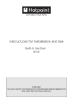
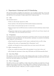
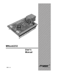
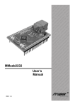
STK300 USER MANUAL
Published by
KANDA SYSTEMS LTD.
www.kanda.com
Page 1
STK300 User Manual
Copyright © Kanda Systems Ltd. 1999.
All information contained in this publication, including product data, diagrams and
charts, represent information on products at the time of publication, and are subject to
change by Kanda Systems Ltd. without notice due to product improvements or other
reasons.
Kanda Systems Ltd. assumes no liability for the accuracy or use of the information.
Kanda Systems Ltd. assumes no responsibility for any damage, or infringement of any
third-party’s rights, originating in the use of any product data, diagrams, charts or
circuit application examples contained in this publication.
All copyright and trademarks are recognized and are the property of their owners.
No part of this publication may be reproduced or distributed in any form or by any
means, or stored in a database or retrieval systems, without the prior written
permission of Kanda Systems Ltd., except in the case of brief quotations embodied in
critical articles and reviews.
© Copyright 1999 Kanda Systems Ltd. all rights reserved.
Version 1
Kanda Systems Ltd.
Unit 17/18
Glanyrafon Enterprise Park
Aberystwyth
Ceredigion
SY23 3JQ
UK
Page 2
Introduction
Welcome to the Kanda 300 Development Kit.
This system incorporates an In System Programming unit and an applications board.
For late breaking news and any manual errata always check the README.TXT file included with
the software.
Device Support
The system software currently has support for the following devices.
•
•
•
•
AVRMEGA103
AVRMEGA103L
AVRMEGA603
AVRMEGA603L
Upgrades for new devices will be available via the Internet from www.kanda.com
Kanda Systems cannot be held responsible for any errors or omissions in this system. The limit
of any liabilities is limited to providing replacement hardware or software.
Page 3
Getting Started
Unpacking the system
You will find the following items in the box:
•
•
•
•
Main Board
1 Disk set
ISP Dongle
ISP Ribbon Cable
System Requirements
The minimum hardware and software requirements are:
•
•
•
•
80386 processor or above (486 or above recommended)
1MB RAM
1MB free hard disk space
Windows 95/98/NT
Page 4
Connecting the system
Connect Lead supplied
to Dongle and insert in
PC Printer Port or
Serial Port
Power Supply
9 - 15 V DC
7 - 12V AC
Plug header on
lead into
Programming
Interface - Key way
gives orientation
Power Connector
5.5/2.1 Barrel
On-Off Switch
RS232
On/Off Power Connector
Switch Connector
Programming
Interface
RS 232 Connector
Not used for
programming
Port Headers
A power supply is required with a standard 2.1mm barrel connector. It can be AC (7 - 12 V) or
DC (9 - 15 V). The connector is inserted into the power connection socket as shown.
The programming lead supplied is fitted into the Dongle case and the other end is inserted into the
programming interface on the board as shown.
The Dongle case is connected to one of the printer ports on the PC. If this is not LPT1, then you
will need to change the printer port setting in the software - see software section for details.
Page 5
Hardware Description
The main features of the board are shown in the diagram below.
LCD
Contrast
Adjustment
LCD Connector
LK1 - Cut for A/D
External Reference
Analog Reference
Voltage Adjustment
Analog I/P
External
Memory
Expansion
Plug in MEGA
board here
Ext. SRAM
Port A Digital
Address Latch
IC for RAM
Port B Header
Selector for
RS232
4MHz Crystal
ISP Interface
O/P pins for
Ve supply to
Op-Amp etc.
Power On
and Program
lights
Port C
Header
Port D
Header
Port B
Jumpers
Disable LEDs
Port D Jumpers
Disable Switches
Port E Header
Power Input
9-15V DC or
7-12V AC
Misc Header for
non-port pins
On-Off
Switch
JP1 Jumper for 3.3
or 5V Vcc Select
8 switches on Port D
8 LEDs on Port B
JP2 for Brown-out
at 3.3V or 5V
Note: There are a number of jumpers on the board which are used to select different operations
and voltages. The default jumper settings are for programming operations at 5V (JP1 Closed)
with brownout also set to 5V (JP2 Open).
To carry out other operations, some jumpers may have to be removed - refer to the relevant
section for details. A full list of the jumpers and links are given in the table overleaf.
Page 6
Jumpers and links and their functions
Jumper
JP1
JP2
PE0
PE1
Port B
Port D
LK1
CUT Under
Board
Function
Voltage select
Brown out select
RS232 RXD
RS232 TXD
LEDs
Switches
Analogue
Reference
LCD Contrast
Open
5v
2.9V
Port E.0
Port E.1
LEDs Disabled
Switches Disabled
if LK1 cut then
EXTERNAL REF
from header
If Cut, add extra
resistor
Closed
3.3V
4.5V
RXD
TXD
LEDs Enabled
Switches Enabled
ONBOARD POT
Default
Open
Closed
Port E.0
Port E.1
Closed
Closed
Closed
Contrast Pot
Closed
External Connections
All Ports are brought out to edge of board on to headers. Each header has a Vcc and Ground pin
for power supply to external circuits. Port F is the Analog input port and is on a header marked
Analog. There is an extra six-pin header for miscellaneous functions - Read, Write, ALE, Reset,
Ground and Vcc.
See sections on Using External Connections and Using Analog Functions for details.
Page 7
Installing The Software
Windows 95/98/NT
To install the software please insert the supplied disk or CDROM in your computer and perform
the following steps:
•
•
•
•
•
•
Click on your Start button.
Select Settings.
Select Control Panel
Choose Add/Remove Programs.
Click the Install button.
Follow On-Screen prompts.
The software will then be installed onto your computer and an Icon will be added to your start
menu.
Note: On some PCs, especially laptops, programming problems may occur if the Bios Parallel
Port settings are set to EPP Version 1.7. If programming problems do happen, ensure that the
Parallel Port settings in your BIOS are set to EPP V1.9 not V1.7.
This software does not run on Windows 3.xx.
Note: If you have any problems installing the software or suspect that you have faulty media
please contact our technical support department. Please make sure you have the latest version of
the software installed before contacting the support line.
Telephone:
Fax:
E-mail:
Website
+44 (0) 1970 621041
+44 (0) 1970 621040
[email protected]
www.kanda.com
Page 8
How to use the Software
The Programmer software is shown below:
Window
Selection
Main Menu
Status Indictor and
Message Line
Red = Error
Yellow = In Progress
Green = OK
Device
Selection
Security
Settings
Hardware
Selection
ASCII Pane
- Editable
Memory Buffer
Window
- Editable
Overview
The programmer uses three main displays:
•
•
•
Flash Memory
EEPROM Memory
Status
Data and information is displayed on three screens. You can access each screen with a click on
the relevant button or via the View menu.
The main menu details file and programmer operations and the configuration information is shown
just below the menu bar.
A status indicator at the bottom of the screen shows whether an operation was successful. A red
light indicates an error has occurred.
Page 9
Configuring the software
1. The first step is to choose the type of hardware connection, using the drop-down list at the top
right of the screen. Select E-ISP Serial Port or E-ISP Parallel Port as required. Ensure that
the board is connected to the serial or parallel port as appropriate.
2. Select the required device in the Device drop-down. The memory sizes, fuse availability and
other device specific features are set automatically to fit the selected device.
3. Select the Programmer - Options menu choice.
Tab
Port
selection
Type of
port
Parallel
Description
Select from LPT1, LPT2, and LPT3
COM 1, COM 2, COM3 and COM 4
Maximum Read and Write Timeout settings with a default
of 180000 and minimum Baud rate.
Serial
Maximum Read and Write Timeout settings with a default
of 100000.
Note: If you have Time Out Errors when using the programmer you should try and
increase the time outs.
Voltage
Serial and
Sets the operating voltage. Select the required level of Vcc
Parallel
(Vdd). Most programming operations are at 5v even if the
voltage is set differently. Check the Atmel datasheets for
voltages that can be used on the ports. Note: Some low
voltage parts need 5V for programming.
The selected voltage is applied as soon as the dialog is
closed. It will change to 5V as soon as programming
operations takes place. Selecting Device, Run will reapply the operating voltage selected.
Advanced
options
Serial
Parallel
4. Select the level of programming security required from the Security drop-down menu.
Note: Some Tiny AVR devices, especially early versions, can lock out after the security lock bits
are set. Apply the lock bits after the code has been developed.
Loading Data
1. Select File - Load. A sub- menu enables you to select Flash or EEPROM Memory as the
target for the load operation.
Note: Only INTEL hex files can be used.
2.
Select the appropriate file.
Status light
Description
Red
Error during the load operation, because:
•
the file can not be found
•
the file is not INTEL Hex,
•
the file is too big
•
or any other error
Error message displayed. Click on Error message to view Status window.
Green
Operation successful
Page 10
Yellow
Operation is taking place
This light coding applies for all operations.
3. When a file has been loaded into the Flash memory and the EEPROM memory if required, the
programmer is ready for programming operations. EEPROM data (or Flash data) can be
typed directly into the buffer windows instead of being loaded from a file. The data can be
entered as ASCII characters or as Hexadecimal numbers.
Programming
The programming operations are listed in the Device menu. The programmer must be configured
before programming can be undertaken, and for the Program function, data must be loaded into
the buffer windows
The options listed in the Device menu are:
Option
Erase
Description
The device is erased and code and EEPROM memories will be empty - blank
value is FFh. All Fuse settings will be cleared to default values (see data
book/CD-ROM for device specific fuse information).
Program
Choose Flash, EEPROM, Lock bits or Fuses on the fly-out menu. If Flash or
EEPROM is chosen, then that part of the device is programmed with the
contents of the Flash or EEPROM buffer window respectively. If lock bits are
selected, the security bits are programmed according to the Security Settings
drop-down list described above. If Fuses are chosen, a dialog box appears with
the fuses available on the selected device. Set the fuses to your requirements.
Read
If Flash or EEPROM are selected, the contents of the device memory selected is
uploaded and displayed in the relevant buffer window. If the device is blank,
then all locations will read as FFh. If the security (lock) bits are set, then the
data will be invalid. Selecting Fuses displays the status of the fuses on the
selected device in a list box.
Verify
The contents of the selected memory area (Flash or EEPROM) on the device is
compared with the contents of the equivalent buffer window and any differences
are shown in Red - correct values are shown in Green.
Fuses
Only available with some devices. Used for such functions as clock selection,
etc. You can read or write to the fuses of the selected device.
Run
Converts the board operation to run mode. The operating voltage selected
earlier comes into effect.
Auto Program will run all, or a selection of the above options.
Select Auto-Program Options to set the required programming operations. A list of operations is
displayed:
Page 11
Check the required functions. All the selected functions will run when Auto-Program (F5) is used.
If Program Fuses is available and checked, then another dialog box will appear after this list is
closed where you can set device specific fuses.
Note: Erase the device before programming unless you are adding extra data to existing data in
the device. If you are changing data then you cannot change any programmed bit from a 0 to a 1
without erasing the device first. You can however, change a bit from a 1 to a 0. So BB could be
changed to AA for example but AA cannot be changed to BB. You will not be able to program the
device if the write lockbit has been set.
Warning: Setting Lockbits may mean that you will be unable to perform further verification on the
device, and disable further writing to the device, You will be able to re-use the device if you
perform an erase.
Page 12
Menu and Option Descriptions
File Menu
Load
Save
Reload
Exit
Device Menu
Erase
Program
Read
Verify
Fuses
Run
Auto Program
Auto Program
Options
Programmer Menu
Options
Information
Select memory area/buffer window to load (Flash or EEPROM), then
open the Intel Hex file in the Open File dialog box. A red status
warning light indicates that the file load was unsuccessful. This may
be because the file is not Intel Hex or it is too large for the selected
buffer/memory.
Saves the contents of the buffer selected (Flash or EEPROM) to file.
Choose a filename in the File Save dialog box that appears.
Reloads the buffer (Flash or EEPROM) with the last file opened.
Quits the program. Standard Windows close choices can also be used
to exit the program.
The whole device is erased.
The selected device memory, fuses or lock bits are programmed
The selected device memory or fuses are read
The selected device memory is verified against the buffer contents
This is available if the software and device support this function
Runs the program downloaded to the device on the board.
All operations selected in the Auto Program Options are carried out
Dialog box to set required programming operations that will be carried
out sequentially when Auto Program is pressed.
Dialog box for port selection, read/write timeouts and voltages (1.8 5V). You must choose Parallel or Serial port operation and the correct
device first. Note: Most parts program at 5V even if they are low
voltages for operation.
Shows information about the programmer state e.g. hardware
detected, which port etc.
View Menu
Flash
EEPROM
Status
The Flash Memory Buffer window is displayed.
The EEPROM Memory Buffer window is displayed.
The Status Window is displayed. This lists all operations, error
messages, and status information that have been posted during this
session.
See also Window selection on the next page.
Help Menu
Readme
About
Displays the latest information on the software and devices in the
Status window.
Version and Program information
Page 13
Other Controls
Device Selector
Located at the top left of the screen, this drop-down list is used to select the required device.
Make sure that this selection matches the device you have plugged into the board. Obtain an
upgrade to support new devices as they are released.
Security
Located in the center of the screen, Security is used to select type of access to the device once it
has been programmed. This is done by programming the lock bits, so ensure that the lock bits
are checked in the Device, Auto Program Options if you want security set on the device, or
select Device, Program, Security Lock bits for manual programming.
Hardware Selection
Located at the top right of the screen, the hardware selection must be set to either serial or
parallel port. Which serial or parallel port is used is set in the Programmer, Options menu.
Ensure that the board is connected to the correct port.
Window Selection
Located below the Device field, these three buttons indicate which display is visible.
•
Flash buffer window
•
EEPROM buffer window
•
Status Window
See below for details. Which display is active can also be selected using the View menu. See
previous page.
•
Flash Memory
Displays the Flash memory in a buffer window.
The code to be programmed into the device is loaded into this buffer by the File, Load,
Flash option, or read from the device by the Device, Read, Flash option.
The size of the buffer changes to mirror the Flash memory size on the selected device. If
Device, Verify, Flash is used, the contents of this buffer are compared with the contents of
the Flash (code) memory on the device.
Locations which match are shown in green, mis-matches are shown in red. The data in this
buffer window can be changed or entered as either hexadecimal numbers or ASCII
characters. Holding the mouse cursor over a value brings up a fly-out, which gives the
address and the value in decimal, binary, hexadecimal and ASCII.
•
EEPROM Buffer
Displays the EEPROM memory in a buffer window.
The code to be programmed into the device is loaded into this buffer by the File, Load,
EEPROM option, or read from the device by the Device - Read - EEPROM option. The size
of the buffer changes to mirror the EEPROM memory size on the selected device.
If Device, Verify, EEPROM is used, the contents of this buffer are compared with the
contents of the EEPROM memory on the device. Locations which matches are shown in
green, mis-matches are shown in red. The data in this buffer window can be changed or
entered as either hexadecimal numbers or ASCII characters. Holding the mouse cursor over
a value brings up a fly-out, which gives the address and the value in decimal, binary,
hexadecimal and ASCII.
Page 14
•
Status
This window lists all the operations, status and error messages that have occurred
during the current session. To clear the messages displayed, right-click and select
Clear Status.
Status Indicator
Displays a visual result of the current operation - Red means that the operation failed, Yellow
means it is in progress and Green means it was successful. Further information is given in the
accompanying message. These messages are listed in the Status window.
Page 15
Programming Using the Board
Device Orientation
Before programming a device using the programming module, the device adapter must be
inserted correctly into the programming unit. The adapter itself has a corner cut off, which locates
pin 1 of the device and matches the marking on the main unit. This adapter should be pre-fitted,
but can be replaced if the device programming life is exceeded - refer to your supplier to obtain
new device adapter.
The orientation of the device is vitally important. If you put it in the wrong way then you may
damage the device. DO NOT PLUG A DEVICE ADAPTER IN WITH THE POWER SWITCHED
ON or you may damage it. Similarly never remove the device adapter with the power on.
Voltage Selection
Jumper JP1 is used to select either 3.3V or 5V programming.
For Vcc = 5V remove jumper JP1 - jumper open
For Vcc = 3.3V insert JP1 - jumper closed
Jumper JP2 is used to set Brown-out detector voltage.
For Brown Out = 5V insert jumper JP2 - jumper closed
For Brown Out = 3.3V remove jumper JP2 - jumper open
This should be set to the same voltage as Vcc. If Vcc is set to 3.3V and Brown-out is set to 5V,
then the device will be held in reset and will NOT program. See section on Brown-out Detector for
more details.
JP1
JP2
Power and Lead Connections
The 10 way programming lead is inserted in the box header - the key-way ensures correct
orientation. The computer connections are shown in the section on Connecting the System.
The power supply (9-15V DC or 7-12V AC) is plugged into the power connector (5.5/2.1 Barrel).
The Power ON/Off switch is located next to the power connector. Insert the device adapter before
switching the power on. The power on LED should light when the power is correctly applied.
Your hardware is now ready for programming. Refer to Using the Software description for details
of programming operations. A programming LED indicates programming is happening.
Page 16
Brown Out Detector
The brown out detector circuit is used to detect voltage drops. If a short glitch occurs in the
power, this circuit ensures that the processor resets properly rather than operating randomly.
The brown out detector must be set to the same voltage as the circuit voltage (Vcc) - 3.3V or 5V.
For 3.3V operation, jumper JP2 must be removed (jumper open) and for 5V operation it must be
closed.
Voltage
5 Volts
3.3 Volts
Operating Voltage
4.5 Volts
2.9 Volts
Hysterisis
200 mV
200 mV
These values are approximate and may vary with temperature and other factors.
Page 17
Board Applications
Using Switches and LEDs
The LEDs are connected through a 1K resistor network to Port B.
The switches are connected to Port D.
The switches and LEDs can be disconnected if required, so to use them, ensure that the jumpers
labeled Port B and Port D are closed. The board is also marked with the port pin connection for
each switch and LED.
The ports must be correctly set in software as input or output. This is accomplished by setting the
direction control registers to 0 for input and 1 for output. Typical set up code would be :
mov r16, $ff ; move literal into temporary store register
out DDRB, r16 ; set direction register to ones for output - LEDs
out PORTB, r16 ; switch all the LEDs on
mov r16, $00 ; move literal into temporary store register
out DDRD, r16 ; set direction register to zeros for input - Switches
Using External Connections
•
All the ports are brought out to headers on the edge of the board. In addition to the port pins,
each header has a connection for ground and Vcc to supply external circuits. Note this
voltage (Vcc) will be either 3.3V or 5V depending on the setting of jumper 1 (JP1) and the
brown out detector will operate.
Note : If your circuit is to draw significant current ( >250 mA) then a heat sink will be required on
the on-board regulator - LM317. This device is rated at 1.5 Amps but it does need a heat sink to
supply this current. If your circuit will draw more than 1 amp, you may need a separate power
supply. The ports on the device are connected to the headers marked Port A, Port B, Port C, Port
D, Port E and Analog (Port F). The layout of all the headers is the same and is shown in the
diagram.
Cut Corner shown on
board for orientation
Bit 0 of Port. Same
for all Ports.
BIT 0
BIT 1
BIT 2
BIT 3
BIT 4
BIT 5
BIT 6
BIT 7
Extra Connection
for Ground
GND
Vcc
Misc Header
Page 18
Bit 7 of Port. Same
for all Ports
Extra Connection
for Vcc
The last header labeled Misc has connections to processor pins other than the port pins.
Cut out marked on
board to give
orientation
Read
RD
ALE
EXTERNAL
RESET
Write
WR
Extra Connection for
Ground
GND
Vcc
Extra Connection for
Vcc
If external operations do not want pull-ups on the port pin, both the switches and the LEDs can be
disconnected from the processor. To isolate the LEDs, remove the jumper set labeled Port B, and
to isolate the switches, remove the jumper set labeled Port D.
Using Analog Functions
The A2D converters use the header labeled Analog for the A/D inputs on Port F, which is input
only. A +10V to -10V supply is provided on the connector marked Op-Amp next to the crystal. A
lead from this connector can be used for an external amplifier for the ADC inputs. The layout of
the Analog header is shown below.
Analog Port : Marked on Board
Cut out marked on
board to give
orientation
ADC0 - ADC7 connected to Port F PF0 - PF7
ADC0
ADC1
ADC2
ADC3
ADC4
ADC5
ADC6
ADC7
ANALOG
GND
ANALOG
REF
The A/D converters can use either the on-board (Internal) Voltage Reference or an external
Voltage Reference.
Page 19
Using Internal Reference
To use the internal (on-board) Voltage Reference, the pot marked AREF is used to set the voltage
level. The voltage level can be measured with a meter connected to the header pins labeled
Analog Ref and Analog Gnd in the above diagram or from the two holes marked Meter (+ and -).
Using External Reference
To use the A2D converters with an external Voltage Reference, the link marked LK1 must be cut.
The voltage is applied to the pins marked Analog Ref and Analog Gnd on the Analog header - see
diagram above.
Dual Rail Power Supply
An dual rail power supply is included - marked OP-AMP. It is design to provide a low current
(<2mA) supply for external operational amplifiers for signal conditioning etc. on the ADC inputs. It
is designed to supply +10V and -10V, but this may vary especially if the RS232 is being used.
Using Real Time Clock
A 32768 Hz crystal is connected to TOSC1 and TOSC2 pins - Pin 19 and Pin 18. This can be
used to generate a 1 second pulse by setting Timer 0 to Asynchronous Operation - see data book
for details.
Using External RAM
The AT90MEG103 can be used with external SRAM. A socket is provided for a 28 pin RAM chip
and for an address latch chip. These are next to the device adapter at the top of the board. There
is also a header for further memory expansion, which is connected through the address latch.
The pin functions are marked on the board, including chip select (CS).
RAM recommendations
A low power 62256 SRAM is suggested with an access time of 70 nS. If a very fast RAM is
required, the crystal frequency may need to be increased. If a much slower SRAM is used, the
SRAM Wait State bit must be enabled in user software (see data book). The layout of the 28 pin
RAM socket is shown below, and any RAM with this pin-out could be used.
The RAM is memory mapped to $8000..$FFFF.
Page 20
RAM Socket pin layout
A14
A12
A7
A6
A5
A4
A3
A2
A1
A0
I/O0
I/O1
I/O2
Vss
28
27
26
25
24
23
22
21
20
19
18
17
16
15
1
2
3
4
5
6
7
8
9
10
11
12
13
14
Vcc
WE
A13
A8
A9
A11
OE
A10
CS
I/O7
I/O6
I/O5
I/O4
I/O3
Address Latch.
The board connections are for a 74HC573 device. This device will operate reliably with the 4 MHz
crystal supplied but if a faster crystal is inserted, a faster version of this device may be required 74AHC573 or 74FHC573. Note that this option will alter the EMC characteristics of the board and
the CE mark will no longer be valid without re-testing.
Using Expansion Header
The expansion header (marked Memory Expansion) can be used for memory mapped
peripherals. The Chip Select (CS) line is connected which gives compatibility with most popular
microcontroller peripheral devices e.g. memory, PIAs, timers etc.. The header is mapped from
$0000 to $FFFF, but internal memory will take precedence.
The address latch chip (74HC573) must be inserted before the expansion header can be used,
but the RAM chip can be omitted.
Page 21
Using LCD Connections
The header marked LCD interface is for a standard 2 X 16 LCD. The connections are shown on
the board and in the following table.
Connection
Name
0V
+5
Vo
RS
Wr
E
D0
D1
D2
D3
D4
D5
D6
D7
Function
Ground 0V
Vcc - must be 5V
Contrast
Register Select- A14
Not Write
Enable
Data Bit 0
Data Bit 1
Data Bit 2
Data Bit 3
Data Bit 4
Data Bit 5
Data Bit 6
Data Bit 7
The board is designed for use with an LCD with a Hitachi driver chip built-in, with a contrast pin
voltage of 0 to 5 Volts. The pot next to the LCD connector is used for contrast adjustment.
If you use a different LCD driver, it may have a different voltage contrast range. In order to
accommodate this, add a resistor to the board (shown above) and cut track on underside of board
- marked cut.
This board is not designed for use with back lit LCD modules, so the extra connections needed
are not included and the power supply will not supply the current required.
The LCD must be driven in Memory Mapped Mode as Read and Write are descite pins on the
Mega parts- see data sheet. If the crystal has been changed to a faster crystal frequency,
memory mapped operations will not work.
Using RS232
The connection supplied is a 9-way female D-type, so a “straight through” lead is required - not a
null-modem cable.
The Jumpers in the middle of the board, marked PE0 and PE1 must be set to RS232 not Port or
RXD and TXD will be disabled.
As this board has a 4 MHz crystal, the percentage error on the Baud Rate will be between 0.2 and
7.8%. Replacing the crystal with a 3.6846 MHz or 4.608 MHz crystal will reduce this error to zero
but may have EMC implications.
A standard (straight through) lead is required NOT a null-modem cable.
Page 22
Programming In System
Devices can be programmed in your circuit rather than on the board.
For In System Programming, (ISP), the 10 way programming lead is connected to a dual row 10
way (0.1" pitch) header on your circuit.
You will need to use either a multiplexer chip (such as a 4053) or wire directly to the Pins of the
device. Without a multiplexer chip, Serial Communications and SPI port will be unusable:
In addition the system +5 Volts and Ground need to be connected to the programming lead.
DO NOT EXCEED 5 VOLTS (4.75 TO 5.25 VOLTS is allowed) OR YOU MAY DAMAGE YOUR
COMPUTER. THIS WARNING APPLIES TO ANY ISP SYSTEM. BEWARE !!!
ISP Header Layout
Ground
Vcc
2
10
1
9
MOSI
-PDI
SCK
Key way
MISO
-PD0
RST
LED
470R
Optional Program
Indicator circuit
Page 23
Interface using resistors
Programming Header
SCK
MISO
MOSI
MISO is called PDO and
MOSI is PDI on Mega devices
- Port E bits 0 and 1 NOT pins
on Port B.
SCK-PB1
PB1
PDO-PE1
PE1
PDI-PE0
PE0
User
Circuit
RST
Reset
AVR
Typical resistor values would be 1K. This circuit is fine if ports PB7, PE0 and PE1 are used as
inputs in your circuit and no communications are required. If Outputs are needed or RS2232
connections, especially higher than a few milliamps, then the multiplexed circuit is preferable.
Using an analogue multiplexer IC
RST
74HC4053
PB1
AXY
AX
PE1
BXY
BX
PE0
CXY
CX
A
AY
B
BY
C
CY
Reset
AVR
INH
0V
Page 24
SCK
To ISP
Connector
MISO
MOSI
PB1
PE1
PE0
To User
Circuit
The multiplexer select can be driven from the LED connection on the programming lead (as can a
low power LED with its cathode connected to the LED connection via a suitable resistor -1K5 is
fine-). If you use this connection then the output will be low (0) during programming and a 1 at all
other times. Note that it will float if the programmer is not active (i.e. the software is not running)
so you may need to use a pull up resistor.
Note that all the pins (except ground) will float if the programmer is not active. The device may
then be programmed in the normal way
Page 25
Application Builder
Application
Builder Speed
Button
This image indicates which icon to select, i.e. the one on the left. Alternatively, use the File Menu
and select Application Builder.
Start Window
The first step is to select the device you want to use from the list on the top left, labelled Devices.
Watchdog Timer
Page 26
The on-board Watchdog Timer (WDT) can be enabled or disabled. If it is enabled a prescaler can
be applied to lengthen the WDT time-out period. The minimum time-out period is 16 mS and the
maximum is 2048 mS. If emulation is required it is recommended that the WDT is disabled.
SRAM
External SRAM can be used with some AVR devices - see device data sheets for details. The
external SRAM enable bit must be set (SRE bit in MCUCR Register). Some operations e.g.
memory mapped LCD driving require a longer clock pulse. This can be achieved by inserting a
wait state.
Stack Pointer
This sets the position in memory at which the stack will start, in hexadecimal. The default value
given is the top of internal SRAM in the device selected, as the stack grows downwards in AVR
devices. Change this value if you require the stack elsewhere in internal or external SRAM. By
default, if the box is clear, this value is set to be zero.
Note : AT90S1200 devices have a hardware stack so this option is disabled if this device is
selected.
External SRAM and SRAM wait state are enabled with the two check boxes on the left-hand
side. These options enable external SRAM access and slow the Read/Write pulses if required.
Output Type
The type of code output can be selected. There is a choice of assembler output or C Code.
There are some differences between IAR and Atmel assemblers - include file paths etc. so select
the correct assembly language output type.
Next Button
This button will move you to the next page selected in the Peripherals list. If no peripherals are
selected, a minimal template is generated.
Note: If at any time you press a back button to get to this screen, the device select list
WILL be disabled i.e. You can not change device once you leave this screen.
Page 27
Peripherals Window
Peripherals
The various peripherals are enabled or disabled depending on which device is selected, so this
list acts as a map of the peripherals available on each device. Each peripheral has a separate
page in the Application Builder.
Ports
The ports required are selected in this section. Note that Port C is Output only and Port F is input
only Port A, Port B, Port D and Port E are standard input/output.
ELPM
This choice selects whether the ELMP (Extended Load Program Memory) instruction is set to the
bottom 64K or the top 64K of program memory. This choice is disabled in devices with 64K or
less of program memory.
Page 28
Sleep and Power Down Window
XTAL
The oscillator frequency can be divided by a factor between 1 and 129 to reduce power
consumption when processing power requirements are low. Set the divide factor required in the
spin box. Checking the XTAL Divide box will enable XTAL Divide immediately, but in most
applications this will not be required, so leave the box unchecked and set the XTALEN bit in the
XDIV register when needed (XDIV.7).
Sleep Mode
There are three sleep modes, which can be preset in this option. When sleep mode is required,
set the Sleep Enable bit (SE) just before executing the Sleep instruction (to avoid unwanted sleep
mode). The SE bit is bit 7 of the MCUCR register (MCUCR.7).
Reset Source Checking
It is possible to check which reset source caused a MCU reset but this must be setup first.
Checking this box inserts the correct code for doing this.
Page 29
Timer 0 Window
Timer 0 is an 8-bit timer/counter.
Asynchronous Operation
This timer can be asynchronously clocked from an external oscillator connected to TOSC1 and
TOSC2 pins (pins 19 and 18). It is optimized for a 32.768 KHz crystal for use as a Real Time
Clock, and this crystal is fitted on the STK300 board.
Timer 0 can also operate in PWM Mode or Output Compare Mode or neither.
PWM Enable becomes enabled when Output Compare is Clear and vice-versa.
PWM Enable
This enables Pulse Width Modulation mode for this Timer. The resolution is set to 8-bit. So the
timer counts from $00 to $FF and down to $00. The match value is set in the Compare Value
Field. When the Timer value matches the value set in the Compare Value field (which will occur
twice every cycle - on upcount and downcount), the output action that results on PWM0 (pin 14))
can be set by the Output Action radio buttons :
Disconnected - No effect on output pin
Page 30
Non-inverted - Cleared on upcount, set on downcount
Inverted - Set on upcount, cleared on downcount
Output Compare
The value of Timer 0 is compared with the value set in the Compare Value Field. When a match
is detected, the effect on the output pin (OC0 - pin 14) is set by the Output radio buttons.
If the Clear Timer box is checked, the timer is reset to $00 in the CPU clock cycle after a match.
The output can be configured as illustrated.
Timer 1 Window
Timer 1 is 16-bit and is far more complicated than Timer 0 and has many more operating modes.
Standard Operation
Regardless of which other options are selected, Timer 1 can operate in Timer or Counter mode If
Source is set to Timer, Timer 1 increments from the system clock. If it is set to Counter, it
increments on either rising or falling edge (set by Edge) on T1 pin (pin31 - PD6).
A prescaler can be applied to increase overflow time in timer mode.
Page 31
Input Capture
This option is also always available. When the Edge selected (rising or falling edge) is detected
on ICP pin, the current value of Timer 1 is copied to the Input Capture Register - ICR1. The Input
Capture flag is also set and an interrupt can be generated - Timer 1 Capture.
The other two options are PWM Mode and Output Compare Mode and these are mutually
exclusive. When output Compare is selected, PWM mode becomes disabled, and vice-versa.
Both of these options can use a Counter or Timer Source and can operate with or without Input
Capture.
PWM Mode
This option makes Timer 1 and the Output Compare Registers (OCR1A and OCR1B) act as a
Pulse Width Modulator. The resolution of the output can be 8, 9 or 10-bit depending on the choice
selected in the Resolution box.
The Timer counts from $0000 to TOP value and back to zero. TOP value is either $FF, $1FF or
$3FF depending on the resolution (8, 9 or 10-bit). The default value is TOP, but this value will
give either a constant low or a constant high level on the output pins depending on the settings of
OutA and OutB. Therefore you must enter a value in MatchA and MatchB which is less than
TOP in order to get the modulation on OC1A and OC1B pins respectively.
So, in PWM Mode, Timer 1 counts from $0000 to TOP and down again. This means that there
will be two compare values for OCR1A and OCR1B every cycle - going up and then down - when
the Match values correspond to Timer 1 value. OutA and OutB set the output options when these
matches occur:
Disconnected - No effect on output pins
Non-inverted - Cleared on upcount, set on downcount
Inverted - Set on upcount, cleared on downcount
Output Compare
The other option with Timer 1 is Output Compare Mode. Unlike PWM mode, all 16 bits of the
Output Compare Registers OCR1AL/H and OCR1BL/H are used. These values are set in the
CompareA Value and CompareB Value fields.
Whenever the value of Timer 1 matches these values, the effect on the output pins (OC1A, OC1B)
is specified by the OutputA and OutputB radio buttons.
Clear Timer clears Timer/Counter1 to $0000 in the clock cycle after a compareA match. If this is
not checked, timer/Counter1 will continue to count, unless cleared elsewhere.
.
Page 32
Timer 2 Window
Timer 2 is an 8-bit Timer/Counter.
Standard Operation
Page 33
Regardless of which other options are selected, Timer 2 can operate in Timer or Counter mode If
Source is set to Timer, Timer 2 increments from the system clock. If it is set to Counter, it
increments on either rising or falling edge (set by Edge) on T2 pin (pin32 - PD7).
A prescaler can be applied to increase overflow time in timer mode.
PWM Enable
This enables Pulse Width Modulation mode for this Timer. The resolution is set to 8-bit. So the
timer counts from $00 to $FF and down to $00. The match value is set in the Compare Value
Field. When the Timer value matches the value set in the Compare Value field (which will occur
twice every cycle - on upcount and downcount), the output action that results on PWM2 (pin 17 PB7)) can be set by the Output Action radio buttons :
Disconnected - No effect on output pin
Non-inverted - Cleared on upcount, set on downcount
Inverted - Set on upcount, cleared on downcount
Output Compare
The value of Timer 0 is compared with the value set in the Compare Value Field. When a match
is detected, the effect on the output pin (OC2 - pin 17 - PB7) is set by the Output radio buttons.
If the Clear Timer box is checked, the timer is reset to $00 in the CPU clock cycle after a match.
The output can be configured as illustrated.
Page 34
External Interrupts Window
The AVRMEGA has 23 interrupt sources, including 8 external interrupts (INT0..INT7). If this page
or the next page (Interrupts) are selected, an interrupt template will be generated even if no actual
interrupts are checked.
Interrupts INT0 to INT3 are always low leveled triggered on pin 25 to pin 28 (PD0..PD3). To
select an interrupt, check its box.
Interrupts INT4 to INT7 are triggered by changes on the interrupt pins (pin 6 to pin 9 - PE4..PE7).
The type of change that causes an interrupt can be set with the appropriate set of radio buttons.
These buttons are only enabled when the corresponding interrupt is checked.
Page 35
Interrupts Window
To enable an interrupt, check the corresponding checkbox- note that the external interrupts are on
a separate page. An interrupt template is generated even if no individual interrupts are checked.
The Comparator section is enabled if the Analogue Comparator Interrupt is checked. The
comparator can be disabled, and the cause of the interrupt can be selected. The Comparator
output can be connected to the Input Capture mechanism on Timer 1 and therefore generate an
interrupt on Timer 1 Capture, by checking the Input Capture Enable box.
Page 36
UART and SPI Port Window
UART
The Use UART checkbox can be cleared if SPI is required and UART is not needed.
Crystal Frequency is a drop down box containing the frequency of the crystal currently on your
circuit. The baud rate is that of the COM port being used to communicate with the device.
Assistance with this can be found within your operating system’s documentation. The Application
Builder software calculates the required value to generate the selected Baud Rate at the chosen
crystal frequency.
The options section enables the transmitter and receiver. The 9-bit characters box adds an extra
character that can be used for parity or extra stop bit purposes.
SPI
The SPI Enable section contains an enabling checkbox. If Data order is checked then data is sent
MSB first, otherwise data is sent LSB first. Clock Polarity sets whether the SCK line is high
when idle (box is checked) or low when idle (clear).
Clock phase selects whether the data is read on the start of a clock cycle (checked) or halfway
through a clock cycle (clear). See ATMEL Data book for more explanation.
Master/Slave Select selects whether the SPI is to be configured as a master (checked) or slave
(clear). The Clock Rate drop down box becomes enabled when Master is selected and gives
prescaler options for SCK.
Page 37
Analog to Digital Converter Window
ADC Enable starts the ADC. Please read the ATMEL data book for information on the dummy
conversion needed.
ADC Free Run
Makes the ADC constantly convert, continuously updating the ADC Data Register. If this box is
not checked, the ADC operates in Single Conversion Mode and the ADSC bit (ADCSR.6) must be
set every time a conversion is required..
Page 38
ADC Prescaler
Slows the converter’s input clock down when dealing with XTAL frequencies above 100kHz. The
maximum clock frequency for the ADC is 200KHz (50KHz to 200KHz) so the main oscillator must
be prescaled appropriately.
ADC Channels Used
Selects which input lines (AD7..AD0)are to be used in multiplexed ADC operations. Any pins not
used can be used for standard digital inputs - Port F.
Page 39
Standard Ports Windows
This page is representative of the set-up values for the different standard I/O Ports (A, B, D and
E). The left-hand column controls whether the port data line is an input (checked) or an output
(clear). The second column controls whether the internal pull-up is enabled (checked) or disabled
(clear) - inputs only.
The third column is greyed until the line is selected as an output. The boxes then control the initial
output value, be it 1 (checked) or 0 (cleared).
Note : If a pin has already been allocated to its second function e.g. Counter input, Interrupt pin,
UART TXD, RXD etc. then it is disabled and cannot be reset.
Page 40
Port C Window
Port C is output only, so the only choice is initial output value. If external SRAM is enabled, then
this port is used for the upper byte of the address and is therefore disabled.
Page 41
Port F Window
Port F is input only. Any bits not used by the ADC can be used for standard input.
Page 42
Technical Support
About Kanda Systems
We, at Kanda Systems, design and manufacture all of our own products in the Principality of
Wales. We can also undertake custom design work with both Software (high and low level) and
hardware designs. Please contact us if you would like help with any projects.
Kanda Systems Ltd are a leading supplier of semiconductor tools and development products.
Kanda Systems can help you realise your digital designs by providing everything from software to
hardware solutions. We can offer professional support in the following areas:
•
•
•
•
Development Tools
Device Starter kits, In-Circuit Emulators and Programmers
Training
Logic trainer, ADC Trainer, Switched mode PSU designer, technical books and training
seminars & courses.
Instrumentation & Software
IAR C compilers for most popular microcontrollers, Low cost - high performance PC
based Logic Analysers and Logical Devices full CUPL Software with Schematic
Capture.
Support Services
High volume device programming & design Consultancy.
Contacting Kanda
We would be grateful if you can pass on any errors you may find in this software. We pride
ourselves on our customer support and we can usually solve the problem and send you an update
very quickly (especially if you have email). Similarly if you have any technical support questions
then please contact us.
We can be contacted at:
Kanda-Systems Limited
Unit 17
Glanyrafon Enterprise Park
Aberystwyth, SY23 2JQ
UK
Tel:
Fax:
e-mail:
+44 (0) 1970 621041
+44 (0) 1974 621030
+44 (0) 1970 621040
Technical Support
General Enquiries
[email protected]
[email protected]
We also have an extensive range of development products available, please contact us or see
our
website (http://www.kanda-systems.com) for full details, prices etc.
Software upgrades and free demos are also available on our website.
Page 43
EMC Regulations
This system has been tested to ensure that it complies with the latest regulations for EMC
susceptibility and emissions. It has been passed for conductivity and radiation and conforms to
the regulations in all respects.
However, neither Kanda Systems or Atmel can be held accountable for any user supplied
equipment, such as Power supplies and computers, used with this system. If these parts do not
conform to the EMC regulations, then the complete system will not conform to standards.
The same proviso applies to any user circuitry connected to this system, such as test boards and
modules. If any changes are made to the hardware supplied with this system, such as a change
in the crystal frequency or modifications to tracks or layouts then the system will not conform to
the regulations.
With these factors in mind, users should not use this system in areas where a life threatening
situation could occur as a result of EMC emissions, for example operating theatres. Users of this
system with pacemakers or other medical equipment should consult their medical adviser before
using the system, and if any doubt remains, should retest the complete system, including ancillary
equipment such as computers and power supplies to ensure that the EMC regulations are still
being met.
Page 44
Page 45