1
US008216233B2
(12) United States Patent
(10) Patent N0.2
McClurken et al.
45 Date of Patent:
(54)
SURGICAL DEVICES AND METHODS OF
USE THEREOF
(75)
Inventors. Michael E McClurken, Durham, NH
_
US 8,216,233 B2
6,053,937 A
6,149,646 A
6,485,490 B2
.
(Us); Roger D- Greeleys Portsmouth,
NH (US); Brian M. Conley, South
BerWick, ME (US)
4/2000 Edwards et a1.
11/2000 West, Jr. et a1.
ll/2002 Wampler et a1.
6,575,968 B1
6/2003
6,602,242 B1 *
8/2003 Fung et a1‘ “““““““““ “ 604/528
6,656,174 B1
Eggers et a1.
12/2003 Hedge et a1.
C t- d
( on “we )
FOREIGN PATENT DOCUMENTS
(73) Assignee: Salient Surgical Technologies, Inc.,
Portsmouth NH (Us)
Jul. 10 a 2012
JP
2003079633
3/2003
(Continued)
(*)
Notice:
Subject to any disclaimer, the term of this
patent is extended or adjusted under 35
U'S'C' 154(1)) by 11 18 days'
(21)
International Search Report andWritten Opinion datedAug. 29,2008
APPI' NO‘: 12/053 030
issued in related International Patent Application No. PCT/US08/
’
(22) F1led:
Primary Examiner * Linda Dvorak
SeP- 25, 2008
Assistant Examiner * Khadijeh Vahdat
_
(74) Attorney, Agent, or Firm * Sterne, Kessler, Gold
_
Related US. Application Data
Provisional application No. 60/896,768, ?led on Mar.
Stein & FOX’ P~L_L_C_
23’ 2007_
(57)
Int‘ Cl‘
A61B 18/14
The invention provides surgical devices and methods to treat
tissue. In one device embodiment, the invention comprises a
bipolar electrosurgical device to treat tissue in a presence of
Ulsl
(58)
(Continued)
Pnor Pubhcatlon Data
Us 2008/0234674 A1
(51)
057815.
Mar. 21, 2008
(65)
(60)
OTHER PUBLICATIONS
(200601)
ABSTRACT
- - - - - - - - - - - - - - - - - - - - - - - - - - - - - - - - - - - - - - - - - - - - - - - - - - - - - - - -
Field of Classi?cation Search ..
606/ 41*52
See application ?le for Complete Search history.
_
(56)
References Clted
U.S. PATENT DOCUMENTS
from a distal portion of the device,
a
With the device comprising
a disc shaped distal end. In one method embodiment, the
invention comprises a method of treating tissue having a
blood vessel during spine surgery, With the method compris
ing pressing a portion of the blood vessel against a supporting
spine structure With a surgical device to provide a compressed
4,936,281 A
6/1990 StasZ
portion of the blood vessel, and heating the compressed por
5,098,431 A
3/1992 Rydell
5,383,876 A *
1/1995
tion of the blood vessel With the surgical device suf?ciently to
inhibit a blood ?oW through the vessel after the surgical
device is removed from the blood vessel.
Nardella ....................... .. 606/49
5,395,363 A
3/1995 Billings et a1.
5,460,629 A
5,484,435 A
10/1995 Shlain et a1.
l/l996 Fleenor et a1.
6,004,269 A
12/1999 Crowley et a1.
41 Claims, 15 Drawing Sheets
US 8,216,233 B2
Page 2
US. PATENT DOCUMENTS
6,702,810 B2
3/2004 McClurken et al.
6,960,200 B2
11/2005 Shapeton et a1.
6,979,328 B2
12/2005 Baerveldt et a1.
7104 990
’
’
7,112,199
7,147,637
7 175 644
B2
B2
B2
B2
’
’
7,455,669 B2
7 571729 B2
90006
9/2006
12/2006
2/2007
J nk.
a1
6 ms 6‘ ~
Cosmescu
Goble
11/2008
Swanson
2009/0118732 A1
2009/0156981 ‘A1
2009/0177192 A1
2009/0270856 A1
2010/0036371 A1
Cooper et a1.
8/2009 S
7/2009 RlOuX et al.
10/2009 Saadat et al.
2/2010 Park et al.
2010/0100095 A1
4/2010
2010/0114095 A1
2010/0160906 A1
5/2010 Janssen et al.
6/2010 J
d
am“
2010/0204560 A1
dt t l
5/2009 Desinger
60009 Fay et 31'
8/2010
McClurken et al.
Salahieh et al.
-
2010/0241178 A1
9/2010 T1lson et al.
12/2010 Houser et a1.
7,621,910 B2
11,2009 Sffgia e a'
2010/0312259 A1
738113282 B2
7,819,861 B2
7,819,864 B2
100010 Mcclurken
10/2010 Auge, H et a1~
10/2010 Morgan et al.
2010/0331883 A1
12/2010 SchmltZ et a1.
FOREIGN PATENT DOCUMENTS
2001/0001314 A1 *
5/2001
Davison et al. ............... .. 606/41
2001/0014806 A1*
8/2001
Ellman et al. ..
2002/0049438 Al*
4/2002 Sharkey e161.
606/41
2002/0077626 A1*
6/2002
606/41
Ellman et al. ..
W0
‘VG-02060523
8/2002
606/45
2002/0l98520 A1,, 0/2002 Coen et a1‘ ““““““““““ “ 606/4l
2004/0243121 A1
12/2004 Lee et a1‘
OTHER PUBLICATIONS
.
.
European Search-Report dated Mar. 1, 20101ssued1n related Euro
pean Patent Application No. 08744175.4-2305.
2005/0059966 A1
3/2005 McClurken et a1.
Salameh et al. “An Animal Model Study to Clarify and Investigate
2005/0070894 A1
Zoos/0090816 A1*
3/2005 MCClurken
4/2005 Mcclurken et a1~
Endoscopic Tissue Coagulation byUsingaNeW Monopolar Device,”
Gastrointestinal Endoscopy, Jan. 2004, vol. 59, No. 1, p. 107-112.
Zoos/01543 86 Al
2005/0288665 A1
7/2005 West et a1‘ """""""""" " 606/41
12/2005 WolosZko
3/2006
2006/0106375 A1
5/2006 Werneth et a1.
838-841~
2006/0149225 A1
7/2006 Mcclurken
McCauley Genard, “Understanding Electrosurgery,” MC-55-049
2007/0027449 A1 *
2007/0270791 A1*
2008/0033421 A1
2008/0221567 A1
Desinger et al.
Palanker et a1. “Electrosurgery With Cellular Precision,” IEEE Trans
t.
B.
d. 31 E .
.
F b 2008
l 55 N 2
2006/0052776 A1
2/2007 Godara et a1. ................ .. 606/41
11/2007 Wang et a1. ................... .. 606/41
2/2008 Davis et a1.
9/2008 SiXto et al.
‘1° “ms on
“me 1°
ng‘neenng’
e '
' V0 '
’
°'
’ P'
001 Rev.2, 2010, 16 pages, Bovie Medical Corporation Clearwater,
FL, United States,
* cited by examiner
US. Patent
FIG.1
Jul. 10, 2012
Sheet 1 0115
US 8,216,233 B2
U S. Patent
Jul. 10, 2012
Sheet 2 0f 15
US 8,216,233 B2
5C.
NdE
US. Patent
Jul. 10, 2012
Sheet 4 0f 15
US 8,216,233 B2
250
?mtgfwzro
a-4...
w
.S9
m
w
a....
.-_.
w
OI
'm
_1
H
w
7.
.I1
0
_i
.
,w
-
_
,
m
m
._
4'
.
g
m
Mm
.,
“
\
.,‘2
00
/
4
w
\
nEm
o
Ba
dz
¢--.5
\
;
.F
4
/
m
v- %
Hm
um...»
am
/
In
m
I”
l_I-a
a
-v
.1
m
._
w
,z
/
?
6
0.0Q
\\
/>
w
m
w
m
M
%
a
n
0408
Q
a
.-i
G
_r
a
4.
.
f
tp
H
d(|
//
\m
-.
2B3,52um“62.13
ni
a
O|
/n
u\
I
20
40
60
so
100
120
200
M0
Power Setting (Watts)
1%
-
-
-' Medium QM
"'- —Low QL
FIG. 5
US. Patent
Jul. 10, 2012
Sheet 5 0f 15
US 8,216,233 B2
US. Patent
Jul. 10, 2012
Sheet 6 0f 15
US 8,216,233 B2
US. Patent
Jul. 10, 2012
Sheet 7 0f 15
US 8,216,233 B2
mamt
US. Patent
Jul. 10, 2012
Sheet 8 0f 15
US 8,216,233 B2
US. Patent
Jul. 10, 2012
w.
Sheet 9 0f 15
“Eli
1
FIG“ #0
US 8,216,233 B2
US. Patent
Jul. 10, 2012
Sheet 10 0f 15
US 8,216,233 B2
US. Patent
Jul. 10, 2012
Sheet 11 0115
C), 2
U0
{w S kU
5 E a‘
US 8,216,233 B2
12H
/./~h7 l/. I.Ҥ\
//
. 2%./ _.7
50
,M.
Hui
iii-G9
US. Patent
Jul. 10, 2012
30k:
FIG» E 3
Sheet 12 0115
C
US 8,216,233 B2
US. Patent
Jul. 10, 2012
Sheet 13 0f 15
US 8,216,233 B2
US. Patent
Jul. 10, 2012
Sheet 14 0f 15
US 8,216,233 B2
30%
Pics. I7
/
H461;
H%\
220
(j
/ Mb
\
\
/
r 202
(- 224
2221
/
(‘Z26
200
A’. 230
4\ 231
Fig I?
fm
22°
il-léa
\ 22.2.
j
lil'la.
/
200
/ 2oz
//
Hqb
{22w
r215
I" 230
’\- ZZZ
US. Patent
Jul. 10, 2012
Sheet 15 0f 15
US 8,216,233 B2
FIG. a“;
[1113.30
300‘
Wéék
2Z0
\
6
20K
22%
(2B4,
KGQ
US 8,216,233 B2
1
2
SURGICAL DEVICES AND METHODS OF
USE THEREOF
at a distal end comprising a disc shaped distal end. The disc
shaped distal end comprises a ?rst semi-circular shaped elec
trode and a second semi-circular shaped electrode. The
device may further comprise a ?uid delivery passage being
CROSS REFERENCE TO RELATED
APPLICATIONS
connectable to a ?uid source of ?uid and at least one ?uid exit
in ?uid communication With the ?uid delivery passage.
In another embodiment, the invention provides a method of
The present application claims the bene?t of the ?ling date
of US. Provisional Application Ser. No. 60/896,768, ?led
Mar. 23, 2007, the teachings of Which are incorporated herein
treating tissue having a blood vessel during spine surgery
With the method comprising pressing a portion of the blood
vessel against a supporting spine structure With a surgical
device to provide a compressed portion of the blood vessel,
and heating the compressed portion of the blood vessel With
the surgical device suf?ciently to occlude the blood vessel
after the surgical device is removed from the blood vessel. In
certain embodiments, the supporting spine structure com
prises a vertebra, and more particularly, a vertebral body of
by reference.
FIELD
This invention relates to surgical devices, systems and
methods for use upon tissues of a human body during surgery,
particularly open surgery and minimally invasive surgery
such as laparoscopic surgery.
the vertebra.
In another embodiment, the invention provides a method of
BACKGROUND
20
A dry tip electrosurgical device, such as a Bovie pencil, can
cause the temperature of tissue being treated to rise signi?
cantly higher than 1000 Celsius, resulting in tissue desicca
tion, tissue sticking to the electrodes, tissue perforation, char
formation and smoke generation.
against a bone structure With a surgical device to provide a
25
cally poWered surgical device to be used during a surgical
More recently, ?uid-assisted electrosurgical devices have
30
procedure With the device comprising an aperture formed in
the device; the aperture having a button therein to activate the
device, the aperture de?ned by a perimeter Wall surrounding
such as tissue desiccation, electrode sticking, smoke produc
tion and char formation during the treatment of tissue. HoW
the button; a narroW gap betWeen the button and the perimeter
ever, too much saline can provide too much electrical disper
sion and cooling at the electrode-tissue interface. This
reduces the temperature of the tissue being treated and, in
compressed portion of the blood vessel, and heating the com
pressed portion of the blood vessel With the surgical device
suf?ciently to occlude the blood vessel after the surgical
device is removed from the blood vessel.
In another embodiment, the invention provides an electri
Furthermore, certain surgical devices are too large to be
used in con?ned surgical spaces and/or are simply ineffective
in treating tissue, such as to inhibit blood loss.
been developed Which use saline to inhibit undesirable effects
treating tissue having a blood vessel during surgery With the
method comprising pressing a portion of the blood vessel
Wall, the narroW gap open to a ?oW of ?uid therein from the
surgical procedure, the ?uid comprising blood; and the button
35
having at least one side closely adjacent the perimeter Wall
desired tissue temperature for treatment of the tissue. Long
surrounding the button, the at least one side of the button
having at least one aperture formed therein to inhibit the
treatment times are undesirable for surgeons since it is in the
button from adhering With the perimeter Wall by the blood.
turn, can result in a longer treatment time to achieve the
best interest of the patient, physician and hospital to perform
surgical procedures as quickly as possible.
40
It is understood that the speci?c features described in these
embodiments can be rearranged among the various embodi
ments to provide devices, apparatus, systems and methods
In light of the above, there is a need for devices and meth
ods Which address the foregoing concerns.
that fall Within the scope of this disclosure.
SUMMARY OF THE INVENTION
BRIEF DESCRIPTION OF THE DRAWINGS
45
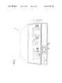
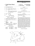
FIG. 1 is a front vieW of one embodiment of a system of the
The invention, in one embodiment, provides an electro sur
gical apparatus to provide controlled delivery of radio-fre
present invention having an electrosurgical unit in combina
quency poWer and a ?uid to an electrosurgical hand held
device to treat tissue. The apparatus comprises a radio-fre
tion With a ?uid source and handheld electrosurgical device;
FIG. 2 is a front perspective vieW of the electrosurgical unit
quency generator to deliver the radio-frequency poWer, With
the radio frequency poWer from the radio-frequency genera
50
FIG. 3 is a rear vieW of the electrosurgical unit of FIG. 1;
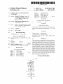
FIG. 4 is a graph of the RF poWer output P0 versus imped
ance Z for the electrosurgical unit of FIG. 1;
tor selectable at a radio-frequency poWer level; a pump to
deliver the ?uid; a primer to prime the hand device With the
?uid; a control system to control a ?oW of the ?uid delivered
by the pump With a functional relationship betWeen the radio
frequency poWer level and the ?oW of the ?uid, the functional
55
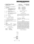
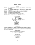
the RF poWer setting PS in units of Watts on the X-axis;
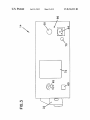
FIG. 6 is a block diagram shoWing one embodiment of hoW
the electrosurgical unit processes the inputs of RF poWer
setting PS and the ?uid ?oW rate setting, either QL, QMor QH,
to control the pump speed;
frequency poWer level; and a ?uid ?oW selector Which
changes the functional relationship betWeen the radio-fre
quency poWer level and the ?oW of the ?uid.
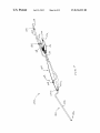
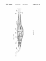
FIG. 7 is an isometric vieW of an assembly of an exemplary
electrosurgical device according to the present invention;
In another embodiment, the invention provides a bipolar
shaft supporting the distal portion of the device in rigid rela
tion to the handle. The distal portion of the device terminates
FIG. 5 is graph shoWing three relationships of ?uid ?oW
rate Q of saline (at high QH, medium QMand loW QL) in units
of cubic centimeters per minute (cc/min) on the Y-axis, and
relationship to increase the ?oW of the ?uid in response to an
increase in the radio-frequency poWer level and to decrease
the ?oW of the ?uid in response to a decrease in the radio
electrosurgical device to treat tissue. The device comprises a
handle and a shaft extending distally from the handle With the
of FIG. 1;
FIG. 8 is an isometric vieW of the inner components of the
65
handle With the handle removed;
FIG. 9 is a side vieW of a handle portion of the device of
FIG. 7 assembled With various components;
US 8,216,233 B2
3
4
FIG. 10 is a close-up side vieW of a button and handle
portion of the device of FIG. 7 assembled With various com
Returning to FIG. 1, ?uid source 22 comprises a bag of
?uid from Which the ?uid 24 ?oWs through a drip chamber 26
after the bag is penetrated With a spike located at the end of the
ponents;
drip chamber 26. Thereafter, ?uid 24 ?oWs through ?exible
delivery tubing 28 to handheld electrosurgical device 30.
Preferably the ?uid delivery tubing 28 is made from a poly
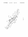
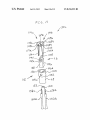
FIG. 11 is an exploded vieW of a distal portion of the device
of FIG. 7;
FIG. 12 is a close-up longitudinal cross-sectional vieW of a
mer material.
distal portion of the device of FIG. 7;
As shoWn in FIG. 1, the ?uid delivery tubing 28 passes
through pump 32. As shoWn pump 32 comprises a peristaltic
pump and, more speci?cally, a rotary peristaltic pump. With a
rotary peristaltic pump, a portion of the delivery tubing 28 is
loaded into the pump head by raising and loWering the pump
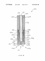
FIG. 13 is a close-up longitudinal cross-sectional vieW of a
distal portion of an alternative exemplary electrosurgical
device according to the present invention;
FIG. 14 is a close-up longitudinal cross-sectional vieW of a
distal portion of an alternative exemplary electrosurgical
device according to the present invention;
head in a knoWn manner. As best shoWn in FIG. 6, ?uid 24 is
conveyed Within the delivery tubing 28 by Waves of contrac
tion placed externally on the tubing 28 Which are produced
FIG. 15 is an isometric vieW of a distal portion of an
alternative exemplary electro surgical device according to the
mechanically, typically by rotating pinch rollers 57 Which
present invention;
rotate on a drive shaft 55 and intermittently compress the
FIG. 16 is a close-up longitudinal cross-sectional vieW of
the distal portion of the device of FIG. 15 taken along line
16-16; and
tubing 28 against an anvil support 58. Alternatively, pump 32
may comprise a linear peristaltic pump. With a linear peri
staltic pump, ?uid 24 is conveyed Within the delivery tubing
28 by Waves of contraction placed externally on the tubing 28
Which are produced mechanically, typically by a series of
compression ?ngers or pads Which sequentially squeeze the
tubing 28 against a support. Peristaltic pumps are generally
preferred, as the electro-mechanical force mechanism, here
rollers driven by electric motor, does not make contact the
?uid 24, thus reducing the likelihood of inadvertent contami
20
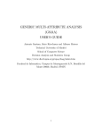
FIG. 17 is a close-up vieW of a distal portion of the device
of FIG. 7 and tissue;
FIG. 18 is a close-up vieW of a distal portion of the device
of FIG. 7 pressing against tissue;
FIG. 19 is a close-up vieW of a distal portion of the device
of FIG. 7 being used to treat tissue; and
FIG. 20 is a close-up vieW of a distal portion of the device
of FIG. 7 removed from treated tissue.
25
DETAILED DESCRIPTION
30
Throughout the description, like reference numerals and
letters indicate corresponding structure throughout the sev
eral vieWs. Also, any particular feature(s) of a particular
exemplary embodiment may be equally applied to any other
exemplary embodiment(s) of this speci?cation as suitable. In
other Words, features betWeen the various exemplary embodi
While a conductive ?uid is preferred, as Will become more
35
not exclusive. From the speci?cation, it should be clear that
40
provides certain advantages over complete elimination of the
?uid and the use of a dry electrode including, for example,
reduced occurrence of tissue sticking to the electrode of
device 30 and cooling of the electrode and/or tissue. There
fore, it is also Within the scope of the invention to include the
use of a non-conducting ?uid, such as, for example, deioniZed
reference from the user of the device, and not the patient.
The inventions disclosed herein provide devices, systems
and methods for treating tissue during a surgical procedure.
These inventions are particularly useful for procedures Where
it is desirable to shrink, coagulate and seal tissue against
apparent With further reading of this speci?cation, ?uid 24
may also comprise an electrically non-conductive ?uid. The
use of a non-conductive ?uid is less preferred than a conduc
tive ?uid, hoWever, the use of a non-conductive ?uid still
ments described herein are interchangeable as suitable, and
any use of the terms “distal” and “proximal” are made in
nation.
In a preferred embodiment the ?uid 24 comprises saline,
and even more preferably, normal (physiologic) saline.
Although the description herein may make reference to saline
as the ?uid 24, other electrically conductive ?uids can be used
in accordance With the invention.
45 Water.
blood loss, for example, by shrinking lumens of blood vessels
As shoWn in FIG. 1, electrosurgical device 30 is connected
(e.g., veins, arteries).
to electrosurgical unit 14 via a cable 34 Which comprises a
The invention Will noW be discussed With reference to the
?gures, With FIG. 1 shoWing a front vieW of one embodiment
of a system of the present invention having an electro surgical
plurality of electrically insulated Wire conductors and at least
one plug 36 at the end thereof. The electrosurgical unit 14
50
unit 14 in combination With a ?uid source 22 and a handheld
electrosurgical device 30. FIG. 1 shoWs a movable cart 2
having a chassis 4 Which is provided With four Wheels 6 for
easy transportation. The chassis 4 carries a vertical support
member 8 comprising a holloW cylindrical post to Which a
storage basket 10 may be fastened and used to store the
38 of electrosurgical unit 14 receives the plug 36 of device 30
therein to electrically connect device 30 to the electrosurgical
55
electrosurgical unit’s user manual, as Well as additional
60
pole 16 having a height Which may be adjusted by sliding the
carrying pole 16 up and doWn Within the support member 8
provided With loops 20 at the ends thereof to provide a hook
for carrying ?uid source 22.
poWer setting display 44 is used to display the RF poWer
setting numerically in Watts. Preferably the poWer setting
display comprises a liquid crystal display (LCD). Addition
As shoWn, cart 2 further comprises a ?uid source carrying
and thereafter secured in position With a set screW. On the top
of the ?uid source carrying pole 16 is a cross support 18
unit 14. Preferably the ?uid delivery tubing 28 is provided as
part of cable 34 and produced With the electrically insulated
Wires via plastic co-extrusion.
FIG. 2 shoWs the front panel of the electrosurgical unit 14.
A poWer sWitch 42 is used to turn the electrosurgical unit 14
on and off. After turning the electrosurgical unit 14 on, the RF
unused devices. Furthermore, the support member 8 carries a
platform 12 comprising a pedestal table to provide a ?at,
stable surface for location of the electrosurgical unit 14.
provides radio-frequency (RF) energy/poWer via cable 34 to
electrosurgical device 30.As shoWn in FIG. 2, plug receptacle
ally, this display 44 is used to display errors, in Which case the
display 44 Will shoW “Err” andblink alternately With a special
65
error code number(s).
The RF poWer selector comprises RF poWer setting
sWitches 46a, 46b Which are used to select the RF poWer
US 8,216,233 B2
5
6
setting. Pushing the switch 4611 increases the RF power set
ting, while pushing the switch 46b decreases the RF power
setting. RF power output may be set in 5 watt increments in
plate 72 which may provide information such as the model
number, serial number, nominal line voltages, frequency, cur
rent and fuse rating information of the electrosurgical unit 14.
The RF power output curve of electrosurgical unit 14 is
shown in FIG. 4. Impedance Z, shown in units of ohms on the
X-axis and output power PO is shown in units of watts on the
the range of 20 to 100 watts, and 10 watt increments in the
range of 100 to 200 watts. Additionally, electrosurgical unit
14 includes an RF power activation display 74 comprising an
indicator light which illuminates when RF power is activated.
Switches 46a, 46b may comprise membrane switches.
In addition to having a RF power setting display, electro
surgical unit 14 further includes a ?uid ?ow rate setting dis
Y-axis. In the illustrated embodiment, the bipolar electrosur
gical power (RF) is set to 200 watts. As shown in the ?gure,
for an RF power setting PS of 200 watts, the output power PO
will remain constant with the set RF power PS as long as the
play. Flow rate setting display comprises three indicator
impedance Z stays between the low impedance cut-off of 30
ohms and the high impedance cut-off of 125 ohms. Below an
lights 50a, 50b and 500 with a ?rst light 50a corresponding to
a ?uid ?ow rate setting of low, a second light 50b correspond
ing to a ?uid ?ow rate setting of medium (intermediate) and a
third light 500 corresponding to a ?ow rate setting of high.
One of these three indicator lights will illuminate when a ?uid
?ow rate setting is selected.
A ?uid ?ow selector comprising ?ow rate setting switches
impedance Z of 30 ohms, the output power PO will decrease
as shown by the low impedance ramp. Above an impedance Z
of 250 ohms, the output power PO will also decrease as shown
by the high impedance ramp.
52a, 52b and 520 are used to select or switch the ?ow rate
setting. Three push switches are provided with the ?rst switch
52a corresponding to a ?uid ?ow rate setting of low, the
second switch 52b corresponding to a ?uid ?ow rate setting of
20
Electrosurgical unit 14 has also been con?gured such that
the pump speed, and therefore the throughput of ?uid
expelled by the pump, is predetermined based on two input
variables, the RF power setting and the ?uid ?ow rate setting.
30
In FIG. 5 there is shown a relationship of ?uid ?ow rate Q in
units of cubic centimeters per minute (cc/min) on the Y-axis,
and the RF power setting PS in units of watts on the X-axis.
The relationship has been engineered to inhibit undesirable
effects such as tissue desiccation, electrode sticking, smoke
production and char formation, while at the same time pro
viding a ?uid ?ow rate Q at a corresponding RF power setting
PS which is not so great as to provide too much ?uid and
associated electrical dispersion and cooling at the electrode
tissue interface. While not being bound to a particular theory,
device 30 with ?uid 24. Priming is desirable to inhibit RF
a more detailed discussion on how the ?uid ?ow rate interacts
power activation without the presence of ?uid 24. A priming
switch 54 is used to initiate priming of device 30 with ?uid 24.
35
with the radio frequency power, modes of heat transfer from
the tissue, fractional boiling of the ?uid and various control
strategies may be found in Us. Publication No. 2001/
0032002, published Oct. 18, 2001, and assigned to the
medium (intermediate) and the third switch 520 correspond
ing to a ?ow rate setting of high. Pushing one of these three
switches selects the corresponding ?ow rate setting of either
low, medium (intermediate) or high. The medium, or inter
mediate, ?ow rate setting is automatically selected as the
default setting if no setting is manually selected. Switches
52a, 52b and 520 may comprise membrane switches.
Before starting a surgical procedure, it is desirable to prime
25
Pushing switch 54 once initiates operation of pump 32 for a
predetermined time period to prime device 30. After the time
period is complete, the pump 32 shuts off automatically.
When priming of device 30 is initiated, a priming display 56
comprising an indicator light illuminates during the priming
assignee of the present invention and hereby incorporated by
reference in its entirety to the extent it is consistent.
cycle.
On the front panel the bipolar activation display 74 illumi
nates when RF power is activated from the electrosurgical
unit 14, either via a hand switch 162 on device 30 (as shown
in FIG. 1) or a footswitch (not shown). A pullout drawer 76 is
located under the electrosurgical unit 14 where the user of
electrosurgical unit 14 may ?nd a short form of the user’s
manual.
FIG. 3 shows the rear panel of electrosurgical unit 14. The
rear panel of the electrosurgical unit 14 includes a speaker 60
and a volume control knob 62 to adjust the volume of the tone
that will sound when the RF power is activated (RF power
activation tone). The volume of the RF power activation tone
40
low, medium and high corresponding to QL, OM and OH,
respectively. Conversely, electrosurgical unit 14 has been
con?gured to decrease the ?uid ?ow rate Q linearly with a
decrease RF power setting PS for each of three ?uid ?ow rate
45
ing exemplary proportionality constants as follows:
50
Qf0.1571XPS
55
electrosurgical unit 14 and an equipotential grounding lug
earth ground using a suitable cable. The rear panel also
FIG. 6 shows an exemplary block diagram of how electro
surgical unit 14 processes the inputs of RF power setting PS
connector 66 used to connect the electrosurgical unit 14 to
includes a removable cap 68 for the installation of a bipolar
footswitch socket connectable to an internal footswitch cir
cuit of electrosurgical unit 14 so that the RF power may be
activated by a footswitch in addition to a handswitch of device
30. Additionally, the rear panel also includes a fuse drawer 70
which includes which contains two extra fuses, consistent
with the line voltage. Finally, the rear panel includes a name
settings of low, medium and high corresponding to QL, OM
and OH, respectively. As shown, QL, OM and OH can be
expressed as a function of the RF power setting PS by chang
is increased by turning the knob clockwise, and decreased by
turning the knob counterclockwise. However, the electrosur
gical unit 14 prevents this tone from being completely
silenced.
Rear panel of electrosurgical unit 14 also includes a power
cord receptacle 64 used to connect the main power cord to the
As shown, electrosurgical unit 14 has been con?gured to
increase the ?uid ?ow rate Q linearly with an increasing RF
power setting PS for each of three ?uid ?ow rate settings of
60
and the ?uid ?ow rate setting, either QL, QM or OH, to control
the pump speed, and therefore the throughput of ?uid
expelled by the pump 32.As shown, user selected input values
for the RF power setting PS and the ?uid ?ow rate setting of
either low, medium and high (corresponding to QL, QM and
OH), as well as activating the priming function, are entered
into electrosurgical unit 14 by pushing corresponding
65
switches for these parameters positioned on the front panel of
the electrosurgical unit 14.
As shown in FIG. 6, the RF power setting switches 46a,
46b, the ?ow rate setting switches 52a, 52b, 52c and the