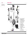
1
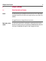
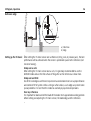
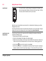
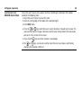
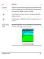
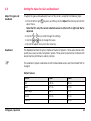
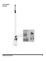
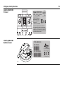
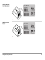
Leica iCONgrade iCP32 User Manual Version 1.0 English iCONgrade, Introduction 2 Introduction Purchase Congratulations on your purchase of iCONgrade machine control system. iCONgrade System is an ideal tool for increasing productivity in all aspects of the construction earthmoving industry. This manual contains important safety directions as well as instructions for setting up the system and operating it. Refer to the chapter "4 Safety Directions" for further information. Read carefully through the User Manual before you switch on the product. To ensure safety when using the system, please also observe the directions and instructions contained in the User Manual and Safety Handbook issued by the: • Machine manufacturer. Product identification The type and serial number of your products are indicated on the label on the base of the unit. Enter the model and serial number in your manual and always refer to this information when you need to contact your agency or Leica Geosystems authorised service workshop. Type: iCP32 Control Box Serial No.: _________________________ Type: MMB1300 Cradle Serial No.: _________________________ Symbols The symbols used in this manual have the following meanings: Type Validity of this manual iCONgrade, Introduction Description Danger Indicates an imminently hazardous situation which, if not avoided, will result in death or serious injury. Warning Indicates a potentially hazardous situation or an unintended use which, if not avoided, could result in death or serious injury. Caution Indicates a potentially hazardous situation or an unintended use which, if not avoided, may result in minor or moderate injury and/or appreciable material, financial and environmental damage. Important paragraphs which must be adhered to in practice as they enable the product to be used in a technically correct and efficient manner. This manual applies to the Control Box iCP32 and the 2D part of the Control Box iCP42. 3 iCONgrade, Table of Contents 4 Table of Contents In this manual Topic 1 Page Product Overview 1.1 1.2 1.3 2 Product Description and Features Getting Started Sensor Setup Keys 6 6 11 13 Operation 16 2.1 16 17 18 19 21 22 23 26 28 32 34 37 39 41 43 45 48 55 2.2 2.3 2.4 2.5 2.6 2.7 2.8 2.9 2.10 Pre-power up checks 2.1.1 Best operation practice for Grader Systems 2.1.2 Mast orientation 2.1.3 No Articulation, circle center shift, or wheel lean on Grader 2.1.4 Grader blade cushioning off 2.1.5 No blade rotation on Dozer Select the Input Source Setting a Reference Height Using the MUS1300 Tri-Sonic Sensor 2.4.1 Installation and Set Up Tri-Sonic Sensor 2.4.2 Operation with the Tri-Sonic Sensor 2.4.3 Swap Function Using the Laser Sensor SP14 Sensor 3D Sensors Setting the Value for Gain and Deadband Sensor Calibration Wizard Machine Setups 3 4 5 6 iCONgrade, Table of Contents Care and Transport 58 3.1 3.2 3.3 3.4 58 58 58 59 General Notices Transport Storage Cleaning and Drying Safety Directions 60 4.1 4.2 4.3 4.4 4.5 4.6 4.7 60 60 61 61 62 66 68 General Intended Use Limits of Use Responsibilities Hazards of Use Electromagnetic Compatibility EMC Labelling Technical Data 74 5.1 5.2 74 81 iCP32 Technical Data Conformity to National Regulations International Limited Warranty, Software License Agreement 82 5 iCONgrade, Product Overview 6 1 Product Overview 1.1 Product Description and Features General The control panel has keys surrounding the screen for user input. The 3.5" colour display, incorporates a state of the art LCD colour screen, making it easy to use, even in bright, sunny conditions. The rugged IP56 enclosure is designed for harsh environments. Power supply, communication The control panel is powered from a cradle based on a sophisticated induction solution, while data is transferred wirelessly via infrared between the MMB1300 cradle and the iCP32 control panel. The MMB1300 will be called the "Cradle" throughout this manual. iCP32 control panel a b b c c d iCP32_001 a) b) c) d) Warning Graphical display Grade indication LEDs Left/Right side sensor setup Speaker e f g e) Menu key f) Function keys g) Enter key This product may be installed on building machinery only by an appropriately trained and qualified specialist. iCONgrade, Product Overview 7 iCONgrade, Product Overview Warning Keys 8 Unauthorized modification of machines by mounting the product may alter the function and safety of the machine. Precautions: Follow the instructions of the machine manufacturer. If no appropriate instruction is available, ask the machine manufacturer for instructions before mounting the product. Up key Down key Enter key Auto/Manual key Menu key Sensor select key Fuction keys Display a b b c c d d iCP32_002 a) b) c) d) iCONgrade, Product Overview Side shift alignment indication Above grade Left/Right on-grade indication Below grade 9 iCONgrade, Product Overview MMB1300 Cradle 10 a iCP32_003 b d c a) b) c) d) Power and data transfer LED indicators Holding magnets On/off switch Release key for control panel 1.2 Getting Started System start To get the system started complete the following steps: 1. Snap control panel onto cradle. 2 To connect the control panel to the cradle: 1. Put the control panel on the holding hooks in the bottom of the cradle. 2. Then snap the control panel onto the cradle by pressing it towards the cradle. 1 1 iCP32_004 iCONgrade, Product Overview 11 iCONgrade, Product Overview 12 2. Turn on the control panel. To turn the system on and off, use the power switch on the right side of the cradle. This is the master switch for the entire system. Removing the panel will also turn off the power. iCP32_005 2 1 iCP32_006 To release the control panel simply press the release key at the bottom of the cradle and pull the control panel towards you and then lift it up. 1.3 Sensor Setup Keys Sensor setup keys The sensor setup keys are used to choose the type of sensor that the system should run with, and to find and set the reference point for that sensor. The left and right hydraulic channel has four sensor setup keys each: • Auto/Manual key, • up key, • down key, • sensor select key. External Multi Switch for Grader iCONgrade, Product Overview The system can also be fitted with an External Multi Switch. This switch has three keys on it. One Auto/Manual key (Red) and a set of up and down keys (green). These keys have the same function as the corresponding keys on the control panel. 13 iCONgrade, Product Overview External switch for Dozer 14 Toggle the master switch to AUTO to enable automatic control on all channels selected on the control panel. Toggling the master switch to MAN places all channels in manual control regardless of selection on the control panel. iCONgrade, Product Overview 15 iCONgrade, Operation 16 2 Operation 2.1 Pre-power up checks State of the machine Before the system is powered up, please check the state of the machine to make sure that it is configured to function correctly. Check and set When? To learn how, see … Mast perpendicular to wheelbase. For Graders without mast "2.1.2 Mast orientation" slope sensor, and for Dozers, every time the blade changes attack angle (pitch). No articulation and circle side shift Every time a job is to be "2.1.3 No Articulation, on Grader. made with a single eleva- circle center shift, or tion sensor + cross slope wheel lean on Grader" sensor on a Grader. Turn Grader blade cushioning off. Every time you want to "2.1.4 Grader blade cushuse automatic controls on ioning off" a Grader. Dozer blade square. Every time you begin a job "2.1.5 No blade rotation with a single elevation on Dozer" sensor + cross slope sensor on a Dozer 2.1.1 Best operation practice for Grader Systems Hint for best performance Below you will find a list of things that will help achieve the best results when operating a Grader system. • • • • • • • iCONgrade, Operation Ensure that mast is perpendicular to the wheelbase, or use a mast slope sensor. Keep the circle centered under the gooseneck. Do not lean the wheels. Do not articulate the machine. Where possible, move the machine in one direction only; do not turn around. Where possible, set the blade rotation and leave it in the same position. Where possible, run with the slope sensor trailing, not leading. 17 iCONgrade, Operation 18 2.1.2 Mast orientation Mast orientation For Dozers and Graders without mast slope sensor, you must make sure that the mast is at the “as measured” position (that is, the position the mast or masts were in during the mast measure up). On a Dozer this means that the mast should not be mechanically sloped. If for some reason the mast is actually mechanically sloped, a new mast measure up must be done. On a Grader the blade should be tipped back towards its end stop, if that was the original measure position. 2.1.3 No Articulation, circle center shift, or wheel lean on Grader Articulation, circle Centershift, and wheel lean For Grader systems that rely on the cross slope sensor, and a single elevation sensor, you must make sure that the machine is not articulated and that there is no side shift applied to the circle. The front wheels must be upright (not leaned). Okay iCONgrade, Operation Articulated 19 iCONgrade, Operation 20 Circle center shifted Wheel leaned Wheel lean introduces an error in the reading from the mainfall sensor. Articulation and circle Centershift introduce unmeasured blade rotation. Operating with wheel lean, circle centershift or articulation can cause inaccuracy in the cross slope being cut. 2.1.4 Grader blade cushioning off Blade cushioning off Using a Grader’s blade cushioning device at the same time as the blade is being automatically controlled by the system results in poor automatic control performance. Make sure that blade cushioning, if installed, is turned off before working with automatic controls. iCONgrade, Operation 21 iCONgrade, Operation 22 2.1.5 No blade rotation on Dozer Dozer blade rotation For Dozer systems that use a cross slope sensor you must make sure that the blade is square to the machine (not rotated). Dozer blade square Dozer blade rotated Operating with a rotated blade can cause inaccuracy in the cross slope being cut. When driving on a surface that has 0% cross slope and 0% long slope, the blade can be rotated freely. The bigger cross slope and long slope you are working with, the bigger the error on a rotated blade will be. 2.2 Sensor selection Select the Input Source 1. Push the left or right key to open the sensor selection menu. Following screen appears: iCONgrade, Operation 23 iCONgrade, Operation 24 2. Use the / keys to scroll through the available sensors. a) If the sensor is connected and active it will show up in black. b) If it’s not connected or inactive it will show in red. 3. Highlight the sensor that is going to be used and exit the sensor selection menu by pressing or . 4. The chosen sensor is indicated by a small icon in the upper corner of the display, and by an icon shown on the blade in relation to the actual placement of the sensor. Example: a b a) Laser indication b) Cross Slope A cross slope is selected in the right side and in the left side a Laser Sensor is selected. iCONgrade, Operation 25 iCONgrade, Operation 26 2.3 Setting a Reference Height Inspection When a sensor is selected the control panel automatically uses the last set reference height for that sensor. There are two ways to change the reference: • Manual mode • Seek mode Manual mode Seek mode Use the / keys to change the reference height up or down. Press the and keys simultaneously to enter the seek mode. In seek mode the screen shows the current sensor value of the selected sensor. Pressing both keys simultaneously again exits the seek mode. Or press or for seek mode. While in Seek Mode, the height values at the top of the screen will be green. If both keys are pressed, and held for more than three seconds, the control panel will take the current sensor value and store as the new reference height. While holding these buttons, the key will change from Seek to 0.0. Once the new reference height has been set, the height values at the top of the screen will change back to black. Automatic detection of the laser beam For systems with a MPM700 Electric Mast, entering seek mode will start an automatic search for the laser beam. If the laser sensor is out of beam the operator can select in which direction the mast should start moving to look for the laser beam using the and keys. The mast will then start moving in that direction until the laser sensor has the beam centered. If the mast, during a seek reaches its top or bottom limit it will automatically switch moving direction, and continue to seek for the laser beam until it is found or it hits the next end point. iCONgrade, Operation 27 iCONgrade, Operation 28 2.4 Using the MUS1300 Tri-Sonic Sensor Using Tri-Sonics The Tri-Sonic can also measure the horizontal distance to a stringline and therefore it can be used to control the sideshift on a grader. To do that, complete the following steps: 1. Place the machine so that the Tri-Sonic is above ground, the edge or stringline. The sensor needs an edge or string to follow before it can control the sideshift. 2. Move the blade to the working position. 3. Move the Tri-Sonic to a good working height. This is approximately 60 cm above the reference. 4. Select the Tri-Sonic on the same side as where it is placed on the machine. 5. Enter the Tri-Sonic menu. First press the key, then press the Adjust function key. Select between the different modes: • Ground Mode • Edge Mode • Stringline Press the or key to toggle between the modes. Once selected press the Following screens will appear by pressing the up ( between the screens. iCONgrade, Operation ) or down ( key. ) Enter key to toggle 29 iCONgrade, Operation 30 Stringline describes the window where the Tri-Sonic will work within certain range. All readings outside of this range will be ignored. Sideshift works only with the Edge and Stringline modes. 6. Go to the Sideshift menu option and set it to Yes. 7. Press both and keys simultaneously to set the control panel in seek mode. 8. Check that the height is approximately 60 cm. 9. Press both and keys simultaneously, or press seek function key, and keep them pressed for three seconds to set the reference height. 10. Press the right key to set the machine in Auto-Mode. 11. Press the Side A/M function key to enable the automatic sideshift control. iCONgrade, Operation 31 iCONgrade, Operation 32 2.4.1 Installation and Set Up Tri-Sonic Sensor Mounting the Tri-Sonic Sensor The Tri-Sonic can be installed quickly and easily with the simplest of tools. Mount a support in a suitable location that is adjustable for height and lateral motion. This will enable setting up of the Tri-Sonic over any reference. The support may differ according to the machine and reference. The direction of movement of the Tri-Sonic sensor In case of large differences in temperature between the storage and working environments, allow 30 minutes for the sensor to adapt to the working environment prior to operation. While ground and curb scanning, the Tri-Sonic should move longitudinally for the averaging of the scanned values. For Stringline and Edge the Tri-Sonic should be placed at an angle of 90° to the reference with the face plate orientated to back of the machine. a b a) Working direction b) stringline Stringline and Edge sensing For stringline sensing, the Tri-Sonic must be positioned across the reference wire. The Automatic Side Shift control of the Tri-Sonic will keep the sensor always over the reference using the hydraulics of the third valve section to regulate the Blade in and out. Mounting the Tri-Sonic on the support Normal operation 1. Release the clamping screw on the support. 2. Insert the round centering pivot on the top of the sensor housing vertically into the support. 3. Rotate the sensor to the required sensing mode (refer to previous page). 4. Lock the centering pivot of the sensor with the clamping screw. Edge operation For sensing Edges it is required to tilt the sensor toward the Edge, as shown on the picture. Slacken the knob on the bracket, tilt the bracket and tighten the knob again. iCONgrade, Operation 33 iCONgrade, Operation Caution 34 System Components can protrude from the machine, which could lead to bodily injury and/or product damage. Precautions: Exercise caution in operation to avoid striking any objects or persons near the working area. 2.4.2 Operation with the Tri-Sonic Sensor iCP32 system flexibility Multifunctional and multitask - iCP32 system can be operated in various combinations for the most demanding job requirements. Mount the Tri-Sonic Mount the Tri-Sonic to the appropriate height for its maximum performance according to the reference used. The sensing range shows the mimimum and maximum values possible, wherever it can be achieved to obtain the range of best perfomance. Sensing range Reference Sensing Range Best Performance String 15-36 inch (38-91 cm) 24 inch (60 cm) Edge 15-36 inch (38-91 cm) 24 inch (60 cm) Flat Ground 15-99 inch (38-250 cm) 24 inch (60 cm) Reference ground a 90° b a) Side View b) Ground Reference stringline a 90° b a) Side View b) String iCONgrade, Operation 35 iCONgrade, Operation 36 Reference edge a 90° b a) Side View b) Edge Setting up the Tri-Sonic When setting the Tri-Sonic sensor over a reference (string, curb, or previous pass), the best performance will be achieved when the sensor is positioned square to the reference (not turned or leaning). Setup over a curb When setting the Tri-Sonic sensor over a curb, it is generally recommended to use the GROUND mode and use the flat surface of the gutter as the reference as shown here. Setup over an EDGE Use of the curb edge as a reference requires extra care be taken to ensure a proper distance and control of iCP32 system. Unlike a string or a flat surface, a curb edge can present some special problems. It is best that this mode be used only by experienced operators. Over any reference It is important to rotate and roll the blade of the Grader to its approximate working position before setting and adjusting the Tri-Sonic sensor, the blade edge, and the reference. 2.4.3 Swap Function Set up and operation The swap function allows the operator to quickly and easily swap sensors, turn the machine around, and grade in the opposite direction by following the previously pass. There are two levels to the swap function available: • Level 1: Swap the cross slope by inversing the actual target cross slope. For example: +2,3% -> -2,3%. • Level 2: Swap the cross slope by inversing the actual target cross slope and swap the side of the Grader that is controlled by ultrasonic. Level 1 By pressing The SWAP function can also be activated by pressing the up key on both external multi switches simultaneously. Level 2 / SWAP the actual target slope will be inversed. Requirements: Two Tri-Sonic sensors must be connected and the system must be in Grader mode. 1. Move the Grader to a flat level ground. 2. Set the moldboard level with the machine. 3. Select slope on left side and sonic on right side. Choose ground mode for the Tri-Sonic. 4. Manually set the cross slope of the blade to level. 5. Set the height for the right sonic by pressing and holding 6. Press / SWAP and the sensors will switch sides. / SEEK for 2 sec. 7. Set the height for the left sonic by pressing and holding / SEEK for 2 sec. The machine is now ready for the final grade following the previously pass. iCONgrade, Operation 37 iCONgrade, Operation 38 It is possible to have different heights and mode settings for the two Tri-Sonic sensors. 2.5 Using the Laser Sensor Laser Sensor MLS700 The Laser Sensor is used to measure the elevation of the blade. This is done by measuring the distance from where the laser beam is hitting the laser and the centerline on the Laser Sensor. When the Laser Sensor detects a laser beam this is indicated on the display by a red line through the laser icon. If at some point the laser beam is lost while the control panel is set in auto mode, it will give a beep and a red cross will appear with a text message saying laser beam lost. Laser Sensor and manual mast To use the Laser Sensor with a manual mast for controlling the elevation of the blade complete the following steps: 1. Select the Laser Sensor on one of the sides. 2. Place the cutting edge of the blade at the desired height. 3. Move the mast up or down until the Laser Sensor detects the laser beam. Continue to move the mast until the indication led's on the Laser Sensor is showing a green line. 4. Press the left key to set the machine in Auto-Mode. 5. When the control panel is in Auto-Mode the machine will start to move the raise/lower hydraulic cylinders so that the laser beam always is in the center of the Laser Sensor. iCONgrade, Operation 39 iCONgrade, Operation Laser Sensor and MPM700 Electric Mast 40 To use the Laser Sensor with a power mast for controlling the elevation of the blade complete the following steps: 1. Select the Laser Sensor in one of the sides. 2. Place the cutting edge of the blade at the wanted height. 3. Enter SEEK mode. 4. Press the or key to tell the mast in which direction it should start to seek. The mast will now move in the given direction until the Laser Sensor detects the laser beam, and has it in the center of the sensor. 5. Press the left key to set the machine in Auto-Mode. 6. The and keys can now be used to move the mast up or down, and thereby changing the elevation reference. 2.6 SP14 Sensor Introduction The SP sensor is a new technology in machine automation. It improves smoothness obtained with GPS, PowerTracker and laser reference sensors. In addition, the dozer can be operated with increased speed compared to a system without SP technology. Enabling the SP14 Sensor iCONgrade, Operation The SP Technology can only be used on Dozers with the Control Box iCP42, together with PowerBox or PowerTracker. The SP Technology MUST be turned off when using the SP14 sensor together with a laser or sonic sensor. If the system is equipped with a SP sensor it is recommended to have it enabled at all times. SP functionality can be enabled or disabled in the tech-mode. 41 iCONgrade, Operation Benefits from using the SP14 Sensor 42 For a system with GPS, SP technology results in greater smoothness, increased operation speed and a system that is more robust against poor GPS coverage. For a system with PowerTracker, SP technology results in greater smoothness, increased operation speed and a system that is more robust against losing the prism in case of the beam being interrupted. 2.7 3D Sensors How to set 3D sensor type Select 3D Height (press the left or right (sensor) key once), and then press the Adjust function key to enter the adjust menu. Note that it's only the current selected sensor in either left or right side that is adjusted. If the 3D system is configured to indicate which sensor is currently in use, select AUTO. If not, then select either TRACKER or GPS from the menu. Once Auto / GPS / Tracker is selected, it is required to EXIT from this menu for the change to take effect and then re-enter the menu to adjust gains. Gains need to be set for both GPS or Tracker depending on which sensor is used. If AUTO is selected, the iCP32 will use the gains set in the Tracker and GPS settings. Use the right arrow key to enter the gains settings. Refer to chapter "2.8 Setting the Value for Gain and Deadband" for configuring Gains. iCONgrade, Operation 43 iCONgrade, Operation 44 To select 3D Slope, Press the left or right (sensor) key once, and then press the Adjust function key to enter the adjust menu. Note that it's only the current selected sensor in either left or right side that is adjusted. Set gains for 3D Slope as explained in chapter "2.8 Setting the Value for Gain and Deadband". 2.8 Setting the Value for Gain and Deadband Adjust the gain and deadband To adjust the gain and deadband of each of the sensors complete the following steps: 1. Press the left or right key once, and then press the Adjust function key to enter the adjust menu. Note that it's only the current selected sensor in either left or right side that is adjusted. 2. Use the or key to scroll through the settings. 3. Use the or key to change the value. 4. To exit the adjust menu press the menu key. Deadband The deadband controls the precise motion of machine hydraulics. These values do not correspond to accuracy but only to hydraulic speeds. These values should not be confused with overall machine performance and/or precision. The automatic hydraulic calibration will set the dead band values, and these should NOT be changed. Default values: iCONgrade, Operation Sensor Dozer Grader GPS 1.0 cm 1.0 cm Laser 0.7 cm 0.7 cm Cross slope 0.6 % 0.3 % Tracker 0.5 cm 0.5 cm Sideshift --- 2.0 cm 45 iCONgrade, Operation Gain 46 This is the scaling of hydraulic speeds for each of the sensors. To enter Gains select the Lower Left or Lower Right buttons to open up the available sensors. Select appropriate sensor and then the or key (depending on left or right side) to enter the Adjust Menu. The automatic hydraulic calibration will calculate the optimal gain values. It is recommended not to change these values. Elevation: Press the Test button to adjust the value so that it corresponds to the below distances. For example, during 2 seconds of movement, the blade should move 13 cm for GPS. Sensor Dozer Grader Laser/Sonics/Tri-Sonics/GPS 13 cm 13 cm Tracker 7 cm 7 cm Second laser for cross slope: This should be measured 1.5 meters from the centre of the blade. Press the Test button to adjust the value so that it corresponds to the below distances. For example, during 2 seconds of movement, the blade should move 8 cm for a laser sensor controlling tilt. Laser: 8 cm. 2D and 3D cross slope sensor: This should be measured 1,5 meters from the centre of the blade. Press the Test button to adjust the value so that it corresponds to the below distances. For example, during 2 seconds of movement, the blade should move 8 cm for 3D cross-slope on Dozer. Sensor Dozer Grader 2D and 3D cross-slope 8 cm 14 cm Sideshift (Grader only): Enter the Tri-Sonic or 3D height adjust menu. Press the Test button to adjust the value so that it corresponds to the below distances. 2D and 3D sideshift: 13 cm. iCONgrade, Operation 47 iCONgrade, Operation 2.9 Enter the Sensor Calibration Wizard 48 Sensor Calibration Wizard In order to maintain the correct calibration of the sensors, the Sensor Calibration Wizard should be run periodically due to blade wear. This should also be done when changing the blade wear edges or changing tires on a grader, as this will change the mainfall slope. This is done by entering the calibration wizard: Menu -> Calibration -> Sensor Calibration and following the on-screen instructions. Sensor Calibration 1. step Select the Sensor Calibration. Follow the on-screen instructions to calibrate each sensor. The following example is for graders, but the dozer sensor calibration is similar. Warning Screen If any sensors are not installed or not connected a warning screen will appear. Sensor Calibration 2. step Park the machine on a flat, hard and level surface, preferably a paved road or similar. This will facilitate turning the machine around and proper machine alignment. If the machine is already aligned properly and is ready for calibration, skip ahead by pressing “Skip” (F2). To start, select “Next”. iCONgrade, Operation 49 iCONgrade, Operation 50 Sensor Calibration 3. step Straighten the machine’s front wheels and articulation. This ensures correct values for calibrating the mainfall sensor. Select“Next” when complete. Sensor Calibration 4. step Centre the machine link bar. It must then be set in its centred position for proper Cross Slope calibration. Select “Next” when complete. Sensor Calibration 5. step Centre the Blade Sideshift, ensuring the distance from the machine base to the blade tip is the same on both sides. This is important for the measurements in the next step. Select “Next” when complete. Sensor Calibration 6. step Rotate the blade so that the distance from the swivel to each blade tip is the same. This ensures that the blade is perfectly perpendicular to the axis along the machine. This is important for the correct calibration of the rotation sensor. Select “Next” when complete. iCONgrade, Operation 51 iCONgrade, Operation 52 Sensor Calibration 7. step Mark the positions of the wheels on the ground and place the blade gently on solid blocks or other solid reference, ensure the blade has not rotated or sideshift has been altered. Select “Next” when complete. Sensor Calibration 8. step The rotation sensor will automatically calibrate, while at the same time collecting Mainfall and Cross Slope data. Select “Next” when complete. Sensor Calibration 9. step Turn the machine around and place the blade gently on the same blocks or reference as before, ensuring that the blade is not rotated or sideshift has altered. Align the wheels using the markings from the previous step. This is important for the correct measurement of the Mainfall and Cross Slope values. Select “Next” when complete. Sensor Calibration 10. step The Mainfall and Cross Slope sensors will now be automatically calibrated. Select “Next” when complete. iCONgrade, Operation 53 iCONgrade, Operation Sensor Calibration 11. step 54 The calibration routine is complete. Save the calibrated values and exit the wizard by pressing “Save”. To exiting the wizard without saving, press “Exit”. 2.10 Machine Setups Grader Setup c a c d b MLS700 f e MLS700 f g h h i g a) b) c) d) e) f) g) j k iCONgrade, Operation h) i) j) k) iCP32 Control panel MMB1300 Cradle External Multi Switch Cross slope sensor Rotation sensor Laser receiver MPM700 Electric Mast/manual mast Sonic Tracker MJB1301 Junction box Grader Hydraulic valve Machine battery 55 iCONgrade, Operation 56 Dozer Setup d d MLS700 MLS700 a c b f e g e a) b) c) h d) e) i f) g) h) i) j k k j) k) iCP32 Control panel MMB1300 Cradle External Switch for Dozer Laser receiver MPM700 Electric Mast/manual mast MJB1300 Junction box Dozer Machine battery Hydraulic valve Cross slope sensor or SP14 Sensor Remote junction box Remote display iCONgrade, Operation 57 iCONgrade, Care and Transport 58 3 Care and Transport 3.1 General Notices General information Servicing the system only requires a minimum of time. All electronic components are enclosed in robust housings to safeguard them against mechanical damage. Periodic checks If any iCP32 components are subjected to severe impact, be sure to check for proper operation prior to performing any work with the system. 3.2 Transport Transport in the field When transporting the equipment in the field, always make sure that you carry the product in its original transport container. Transport in a road vehicle Never carry the product loose in a road vehicle, as it can be affected by shock and vibration. Always carry the product in its transport container and secure it. Shipping When transporting the product by rail, air or sea, always use the complete original Leica Geosystems packaging, transport container and cardboard box, or its equivalent, to protect against shock and vibration. 3.3 Storage Product Respect the temperature limits when storing the equipment, particularly in summer if the equipment is inside a vehicle. Refer to Technical Data for information about temperature limits. 3.4 Cleaning and Drying Product • • Cables and Plugs Keep plugs clean and dry. Blow away any dirt lodged in the plugs of the connecting cables. Damp products Dry the products at a temperature not greater than 40°C/108°F and clean them. Do not repack until everything is completely dry. Blow off dust. Use a clean, soft, lint-free cloth for cleaning. If necessary, moisten the cloth with water or pure alcohol. Do not use other liquids; these may attack the polymer components. iCONgrade, Care and Transport 59 iCONgrade, Safety Directions 60 4 Safety Directions 4.1 General Description The following Instructions should enable the person responsible for the product, and the person who actually uses the equipment, to anticipate and avoid operational hazards. The person responsible for the product must ensure that all users understand these instructions and adhere to them. 4.2 Intended Use Permitted use • • • Adverse use • • • • • • • • • Determine the position of a dozer/grader blade or excavator bucket. Calculate the distance between the blade/bucket and a reference model (surface, line or point). Automatic adjustment of a dozer/grader hydraulic system in order to match the blade to the reference model. Use of the product without instruction. Use outside of the intended limits. Disabling safety systems. Removal of hazard notices. Opening the product using tools, for example screwdriver, unless this is specifically permitted for certain functions. Modification or conversion of the product. Use after misappropriation. Use of products with obviously recognizable damages or defects. Use with accessories from other manufacturers without the prior explicit approval of Leica Geosystems. • • Warning Warning Inadequate safeguards at the work site, for example working on roads. Controlling of machines, moving objects or similar monitoring application without additional control- and safety installations. Adverse use can lead to injury, malfunction and damage. It is the task of the person responsible for the equipment to inform the user about hazards and how to counteract them. The product is not to be operated until the user has been instructed on how to work with it. Unauthorized modification of building and constructions machines by mounting or installing the product may alter the function and safety of the machine. Precautions: Follow the instructions of the machine manufacturer. If no appropriate instruction is available, ask machine manufacturer for instructions before mounting or installing the product. 4.3 Limits of Use Environment Suitable for use in an atmosphere appropriate for permanent human habitation: not suitable for use in aggressive or explosive environments. Danger Local safety authorities and safety experts must be contacted before working in hazardous areas, or in close proximity to electrical installations or similar situations by the person in charge of the product. 4.4 Responsibilities Manufacturer of the product Leica Geosystems AG, hereinafter referred to as Leica Geosystems, is responsible for supplying the product, including the user manual and original accessories, in a completely safe condition. iCONgrade, Safety Directions 61 iCONgrade, Safety Directions 62 Manufacturers of non Leica Geosystems accessories The manufacturers of non Leica Geosystems accessories for the product are responsible for developing, implementing and communicating safety concepts for their products, and are also responsible for the effectiveness of those safety concepts in combination with the Leica Geosystems product. Person in charge of the product The person in charge of the product has the following duties: • To understand the safety instructions on the product and the instructions in the user manual. • To be familiar with local regulations relating to safety and accident prevention. • To inform Leica Geosystems immediately if the product and the application becomes unsafe. Warning Warning The person responsible for the product must ensure that it is used in accordance with the instructions. This person is also accountable for the training and the deployment of personnel who use the product and for the safety of the equipment in use. Unauthorized modification of machines by mounting the product may alter the function and safety of the machine. Precautions: Follow the instructions of the machine manufacturer. If no appropriate instruction is available, ask machine manufacturer for instructions before mounting the product. Warning This product may be installed on building machinery only by an appropriately trained and qualified specialist. 4.5 Hazards of Use Warning Only Leica Geosystems authorised service workshops are entitled to repair these products. Caution Warning Warning Warning Installing near mechanically moving machine components may damage the product. Precautions: Deflect the mechanically moving machine components as far as possible and define a safe installation zone. Beware of inadequate steering if machine is defective like after a crash or other damaging events or alterations to the machine. Precautions: Periodically perform control measurements and field adjustments on the machine as specified in the User Manual. While working, construction and grading should be checked by appropriate means, for example spirit level, tachymeter, before and after important measuring tasks. While steering or navigating the machine accidents may occur due to a) the operator not paying attention to the surroundings (persons, ditches, traffic, etc.), or b) malfunctions (…of a system component, interference, etc). Precautions: The operator assures that the machine is operated, guided and monitored by a qualified user (e.g. driver). The user has to be able to take emergency measures, for example an emergency stop. The absence of instruction, or the inadequate imparting of instruction, can lead to incorrect or adverse use, and can give rise to accidents with far-reaching human, material, financial and environmental consequences. Precautions: All users must follow the safety Instructions given by the manufacturer and the Instructions of the person responsible for the product. iCONgrade, Safety Directions 63 iCONgrade, Safety Directions Caution Danger Warning Warning 64 Watch out for erroneous measurement results if the product has been dropped or has been misused, modified, stored for long periods or transported. Precautions: Periodically carry out test measurements and perform the field adjustments indicated in the user manual, particularly after the product has been subjected to abnormal use and before and after important operations. Because of the risk of electrocution, it is very dangerous to use poles and extensions in the vicinity of electrical installations such as power cables or electrical railways. Precautions: Keep at a safe distance from electrical installations. If it is essential to work in this environment, first contact the safety authorities responsible for the electrical installations and follow their instructions. During dynamic applications, there is a danger of accidents occurring if the user does not pay attention to the environmental conditions around, for example obstacles, excavations or traffic. Precautions: The person responsible for the product must make all users fully aware of the existing dangers. Inadequate securing of the work site can lead to dangerous situations, for example in traffic, on building sites, and at industrial installations. Precautions: Always ensure that the work site is adequately secured. Adhere to the regulations governing safety and accident prevention and road traffic. Caution Warning If the accessories used with the product are not properly secured and the product is subjected to mechanical shock, for example blows or falling, the product may be damaged or people may sustain injury. Precautions: When setting-up the product, make sure that the accessories, for example tripod, tribrach, connecting cables, are correctly adapted, fitted, secured, and locked in position. Avoid subjecting the product to mechanical stress. If the product is improperly disposed of, the following can happen: • If polymer parts are burnt, poisonous gas are produced which may impair health. • If batteries are damaged or are heated strongly, they can explode and cause poisoning, burning, corrosion or environmental contamination. • By disposing of the product irresponsibly you may enable unauthorized persons to use it in contravention of the regulations, exposing themselves and third parties to the risk of severe injury and rendering the environment liable to contamination. Precautions: The product must not be disposed with household waste. Dispose of the product appropriately in accordance with the national regulations in force in your country. Always prevent access to the product by unauthorised personnel. Product specific treatment and waste management information can be received from your Leica Geosystems dealer. iCONgrade, Safety Directions 65 iCONgrade, Safety Directions 66 4.6 Electromagnetic Compatibility EMC Description The term Electromagnetic Compatability is taken to mean the capability of the product to function smoothly in an environment where electromagnetic radiation and electrostatic discharges are present, and without causing electromagnetic distur-bances to other equipment. Warning Caution Electromagnetic radiation can cause disturbances in other equipment. Although the product meets the strict regulations and standards which are in force in this respect, Leica Geosystems cannot completely exclude the possibility that other equipment may be disturbed. There is a risk that disturbances may be caused in other equipment if the product is used in conjunction with accessories from other manufacturers, for example field computers, personal computers, two-way radios, non-standard cables or external batteries. Precautions: Use only the equipment and accessories recommended by Leica Geosystems. When combined with the product, they meet the strict requirements stipulated by the guidelines and standards. When using computers and two-way radios, pay attention to the information about electromagnetic compatibility provided by the manufacturer. Caution Warning Disturbances caused by electromagnetic radiation can result in erroneous measurements. Although the product meets the strict regulations and standards which are in force in this respect, Leica Geosystems cannot completely exclude the possibility that the product may be disturbed by very intense electromagnetic radiation, for example, near radio transmitters, two-way radios or diesel generators. Precautions: Check the plausibility of results obtained under these conditions. If the product is operated with connecting cables attached at only one of their two ends, for example external supply cables, interface cables, the permitted level of electromagnetic radiation may be exceeded and the correct functioning of other products may be impaired. Precautions: While the product is in use, connecting cables, for example product to external battery, product to computer, must be connected at both ends. iCONgrade, Safety Directions 67 iCONgrade, Safety Directions 4.7 68 Labelling Labelling iCP32 Control Panel iCP32 Grading 2D Panel P/N: 798669 797050 S/N: xxxxxxxx xxxxxxxx Leica Geosystems AG CH - 9435 Heerbrugg Made in Denmark 20XX Power 12 - 24 V DC, 6A max. iCP32_007 Labelling MMB1300 Cradle TYPE: MMB1300 P/N: 764910 764910 S/N: XXXXXXXX 131441XX iCP41_009 Leica Geosystems AG CH - 9435 Heerbrugg Made in Denmark 20XX Power 12 - 24 V DC, 6A max. Labelling MJB1300 Junction Box TYPE: MJB1300 P/N: 764838 764838 S/N: XXXXXXXX 131441XX Leica Geosystems AG CH - 9435 Heerbrugg Made in Denmark 20XX Power 12 - 24 V DC, 6A max. iCP32_008 Labelling MJB1301 Junction Box TYPE: MJB1301 P/N: 764839 764839 S/N: XXXXXXXX 131441XX Leica Geosystems AG CH - 9435 Heerbrugg Made in Denmark 20XX Power 12 - 24 V DC, 6A max. iCP32_009 iCONgrade, Safety Directions 69 iCONgrade, Safety Directions 70 Labelling MLS700 Laser Receiver TYPE: MLS700 P/N: 760862 760862 S/N: XXXXXXXX 131441XX iCP32_010 Leica Geosystems AG CH - 9435 Heerbrugg Made in Denmark 20XX Power 12 - 24 V DC, 6A max. Labelling MPM700 Power Mast TYPE: MPM700 P/N: 760863 760863 S/N: XXXXXXXX 131441XX Leica Geosystems AG CH - 9435 Heerbrugg Made in Denmark 20XX Power 12 - 24 V DC, 6A max. iCP32_011 iCONgrade, Safety Directions 71 iCONgrade, Safety Directions Labelling MUS1300 Tri-Sonic 72 Art.No. Type: MUS1300 764031 Power: 11-30V , 0.5A max Leica Geosystems AG CH-9435 Heerbrugg Manufactured: 2010 Made in Switzerland Patents: U.S. 5.327.345 4.733.355 S.No. ...... This device complies with part 15 of the FCC Rules. Operation is subject to the following two conditions: (1) This device may not cause harmful interference, and (2) this device must accept any interferences received, including interference that may cause undesired operation. iCP32_012 Labelling MRS1300 Rotation Sensor TYPE: MRS1300 P/N: 767435 767435 S/N: XXXXXXXX 131441XX iCP32_013 Leica Geosystems AG CH - 9435 Heerbrugg Made in Denmark 20XX Power 12 - 24 V DC, 6A max. Labelling MSS1300 Cross Slope Sensor TYPE: MSS1300 P/N: 764842 764842 S/N: XXXXXXXX 131441XX Leica Geosystems AG CH - 9435 Heerbrugg Made in Denmark 20XX Power 12 - 24 V DC, 6A max. iCP32_014 Labelling SP14 SP Sensor TYPE: SP 14 P/N: 782749 782749 S/N: XXXXXXXX 131441XX Leica Geosystems AG CH - 9435 Heerbrugg Made in Denmark 20XX Power 12 - 24 V DC, 6A max. iCP32_015 iCONgrade, Safety Directions 73 iCONgrade, Technical Data 74 5 Technical Data 5.1 iCP32 Technical Data The iCP32 system is designed to operate from standard vehicle power systems at 24V DC check to ensure proper connection and polarity. iCP32 Control Panel MMB1300 Cradle Parameter Specification Power Supply The iCP32 is supplied from the cradle MMB1300 Power consumption < 200 mA Graphic display 4" LCD colour screen Keypad 18 keys, with backlight Interfaces Infrared Dimensions 12.5 x 18.0 x 3.7 cm Weight 0.5 kg Parameter Specification Voltage range 24 V DC (nom.) Dimensions 12.4 x 15.2 x 4.4 cm Weight 0.320 kg Communication (Infrared) 1 Mbit Output 2 x RS232, RX, TX, 12V/2Amp, GND, 2 x CAN and J1939 MJB1300 and MJB1301 Junction Box iCONgrade, Technical Data Parameter Specification Voltage range 24 V DC (nom.) Nominal voltage 24 V DC, Range 10 V-30 V Power consumption < 0.5 A with no sensors and valve connected Dimensions MJB1300: 13.8 x 18.3 x 6.4cm MJB1301: 14.5 x 18.3 x 6.4cm Weight 2 kg Hydraulic Output Settings Proportional valves, On/Off and Danfoss Interfaces MJB1300 Battery MIL Cradle M12 Valves M12 CAN A MIL CAN B MIL CAN A M12 Interfaces MJB1301 Battery MIL Cradle M12 Valves 2x M12 CAN A 2x MIL CAN B 2x MIL CAN A M12 Aux M12 Special feature for MJB1301 Integrated main fall sensor 75 iCONgrade, Technical Data MUS1300 Tri-Sonic MPM700 Electric Mast MM4 Manual Mast 76 Parameter Specification Dimensions 17.2 x 18.3 x 14 cm Weight 2.5 kg Accuracy within ±0.125 cm @ 30.5 cm Input voltage 11 to 30 V DC Power Consumption 0.5 A max. Parameter Specification Voltage range 24 V DC (nom.) Nominal voltage 24 V DC, Range 10 V-30 V Power consumption < 2.5 A Mast height (extended) 2.9 m Mast height (retracted) 1.7 m Mast travel 1.2 m Mast travel speed 85 mm per second Positions repeatability ±1 mm Weight 30 kg Parameter Specification Height (extended) 3.257 m Height (retracted) 1.857 m MLS700 Laser Receiver iCONgrade, Technical Data Parameter Specification Travel 1.4 m Scale Metric/Inch Weight 14 kg Parameter Specification Voltage range 24 V DC (nom.) Nominal voltage 24 V DC, Range 11 V-30 V Power consumption < 500 mA Dimensions 28 x 12 x 7.2 cm (without mounting bracket) Weight 2.5 kg (incl. clamp) Detection angle 360° Linear detection height 190 mm Operating range 300 m radius Sensor pick-up range 18.5 cm Laser requirement All Rotating Lasers (visible HeNe, invisible Infrared diodes Laser) Pulsed display 5 pulses per second 77 iCONgrade, Technical Data MSS1300 Cross Slope Sensor SP14 Sensor 78 Parameter Specification Voltage range 24 V DC (nom.) Nominal voltage 24 V DC, Range 10 V-30 V Power consumption < 0.25 A Dimensions 15.3 x 8.7 x 3.9 cm Weight 0.855 kg Accuracy cross slope ±0.1 % slope at ±25° Working range ±80° Interfaces CAN MIL Parameter Specification Voltage range 24 V DC (nom.) Nominal voltage 24 V DC, Range 10 V-30 V Power consumption < 0.25 A Dimensions 15.3 x 8.7 x 3.9 cm Weight 0.855 kg Accuracy cross slope ±0.1 % slope at ±25° Working range ±80° Interfaces CAN MIL MRS1300 Rotation Sensor Environmental specifications iCONgrade, Technical Data Parameter Specification Voltage range 24 V DC (nom.) Nominal voltage 24 V DC, Range 10 V-30 V Power consumption < 0.25 A Dimensions Ø16.0 x 22.6 x 5.9 cm Weight 1.56 kg Working range 0-360° Temperature Type Operating temperature [°C] Storage temperature [°C] iCP32 Control Panel -20 to +60 -30 to +70 MMB1300 Cradle -20 to +60 -30 to +70 MJB1301 Junction Box -20 to +60 -30 to +70 MJB1300 Junction Box -20 to +60 -30 to +70 MPM700 Electric Mast -20 to +60 -30 to +70 MLS700 Laser Receiver -20 to +60 -30 to +70 MUS1300 Tri-Sonic -20 to +65 -40 to +85 SP14 SP Sensor -20 to +60 -40 to +80 MSS1300 Cross Slope Sensor -20 to +60 -40 to +80 MRS1300 Rotation Sensor -40 to +80 -20 to +60 79 iCONgrade, Technical Data 80 Protection against water, dust and sand Type Protection iCP32 Control Panel IP67 MMB1300 Cradle IP54 MJB1301 Junction Box IP67 MJB1300 Junction Box IP67 MPM700 Electric Mast IP45 MLS700 Laser Receiver IP68 MUS1300 Tri-Sonic IP54 SP14 SP Sensor IP68 MSS1300 Cross Slope Sensor IP68 MRS1300 Rotation Sensor IP67 Humidity Type Protection iCP32 Control Panel Max 95 % non condensing The effects of condensation are to be effectively counteracted by periodically drying out the instrument. 5.2 Conformity to national regulations iCONgrade, Technical Data Conformity to National Regulations Hereby, Leica Geosystems AG, declares that the iCP32 control panel is in compliance with the essential requirements and other relevant provisions of the applicable European Directives. For the declaration of conformity please contact your Leica Geosystems distributor. 81 iCONgrade, International Limited Warranty, Software License Agreement 6 International Limited Warranty, Software License Agreement International Limited Warranty This product is subject to the terms and conditions set out in the International Limited Warranty which you can download from the Leica Geosystems home page at http://www.leica-geosystems.com/internationalwarranty or collect from your Leica Geosystems distributor. 82 The foregoing warranty is exclusive and is in lieu of all other warranties, terms or conditions, express or implied, either in fact or by operation of law, statutory or otherwise, including warranties, terms or conditions of merchantability, fitness for a particular purpose, satisfactory quality and non-infringement, all of which are expressly disclaimed. Software Licence Agreement This product contains software that is preinstalled on the product, or that is supplied to you on a data carrier medium, or that can be downloaded by you online pursuant to prior authorisation from Leica Geosystems. Such software is protected by copyright and other laws and its use is defined and regulated by the Leica Geosystems Software License Agreement, which covers aspects such as, but not limited to, Scope of the License, Warranty, Intellectual Property Rights, Limitation of Liability, Exclusion of other Assurances, Governing Law and Place of Jurisdiction. Please make sure, that at any time you fully comply with the terms and conditions of the Leica Geosystems Software License Agreement. Such agreement is provided together with all products and can also be referred to and downloaded at the Leica Geosystems home page at http://www.leica-geosystems.com/swlicense or collected from your Leica Geosystems distributor. You must not install or use the software unless you have read and accepted the terms and conditions of the Leica Geosystems Software License Agreement. Installation or use of the software or any part thereof, is deemed to be an acceptance of all the terms and conditions of such License Agreement. If you do not agree to all or some of the terms of such License Agreement, you may not download, install or use the software and you must return the unused software together with its accompanying documentation and the purchase receipt to the dealer from whom you purchased the product within ten (10) days of purchase to obtain a full refund of the purchase price. iCONgrade, International Limited Warranty, Software License Agreement 83 Ask your local Leica Geosystems dealer for more information about our TQM program. Leica Geosystems AG Heinrich-Wild-Strasse CH-9435 Heerbrugg Switzerland Phone +41 71 727 31 31 www.leica-geosystems.com Original text 798790-1.0.0en Leica Geosystems AG, Heerbrugg, Switzerland, has been certified as being equipped with a quality system which meets the International Standards of Quality Management and Quality Systems (ISO standard 9001) and Environmental Management Systems (ISO standard 14001). Printed in Switzerland © 2012 Leica Geosystems AG, Heerbrugg, Switzerland Total Quality Management: Our commitment to total customer satisfaction.