1
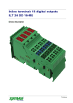
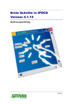
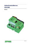
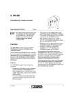
Inline terminal: 8 analog signal outputs ILT AO 4/8/U/BP Device description Preliminary Disclaimer / Imprint This manual is intended to provide support for installation and usage of the device. The information is believed to be accurate and reliable. However, SysMik GmbH Dresden assumes no responsibility for possible mistakes and deviations in the technical specifications. SysMik GmbH Dresden reserves the right to make modifications in the interest of technical progress to improve our modules and software or to correct mistakes. We are grateful to you for criticism and suggestions. Further information (device description, available software) can be found on our homepage www.sysmik.de. Please ask for latest information. SysMik disclaims all warranties in case of improper use or disassembly and software modifications not described in this document or when using improper or faulty tools. Commissioning and operation of the device by qualified personnel only. All applicable regulations have to be observed. SysMik® and the SysMik logo are registered trademarks of SysMik GmbH Dresden. IPOCS™ is © trademark of SysMik GmbH Dresden. "Networking Together!" is subject to copyright of SysMik GmbH Dresden. All other trademarks mentioned in this document are registered properties of their owners. These and further trademarks are used in this document but not marked for better readability. No part of this document may be reproduced or modified in any form without prior written agreement with SysMik GmbH Dresden. Copyright © 2014 by SysMik GmbH Dresden SysMik GmbH Dresden Tel + 49 (0) 351 – 4 33 58 – _0 Bertolt-Brecht-Allee 24 Fax + 49 (0) 351 – 4 33 58 – 29 01309 Dresden E-Mail (Sales) E-Mail (Support) Germany 2 Homepage sysmik.de [email protected] [email protected] www.sysmik.de ILT AO 4/8/U/BP Contents Contents Device description 1 Contents 3 1 Description 4 2 Order information 4 3 Technical data 5 4 Local diagnostic and status indicators / Terminal point assignment 8 4.1 Function identification 8 4.2 Terminal point assignment per each connector 8 5 Internal circuit diagram 9 6 Electrical isolation 10 7 Installation instruction 10 8 Connection notes 11 9 Connection example 11 10 Connecting shielded cables using the shield connector 12 ILT AO 4/8/U/BP sysmik.de 3 Description / Order information 1 Description Note: This device description is only valid in association with the IL SYS INST UM user manual or the Inline system manual of the specifically used bus system. Make sure you always use the latest documentation – it can be downloaded at www.sysmik.de. The terminal is designed for use within an Inline station. This terminal provides an 8-channel output module to output analog standard voltage signals. Features Eight analog signal outputs Actuator connection in 2-wire technology with shield connection Channels are configured independently of one another Diagnostic indicator 2 Order information Description Type Part number Inline terminal with eight analog output chanILT AO 4/8/U/BP nels for analog standard voltage signals; complete with accessories (connectors and labeling fields), transmission speed: 500 kbps Pcs./Pkt. 1225-100492-01-5 1 Optional Add-Ons (Purchase via Phoenix Contact): Description Type Part no. Pcs./Pkt. Inline shield connector for analog Inline terminals IB IL SCN 6-SHIELD-TWIN 2740245 5 Shield connection clamp for applying the shield on busbars SK 8 3025163 10 Shield connection clamp for applying the shield on busbars SK 14 3025176 10 Shield connection clamp for applying the shield on busbars SK 20 3025189 10 Shield connection clamp for applying the shield on busbars SK 35 3026463 10 Support for mounting on the NS 35/7,5 DIN rail, for 10 mm x 3 mm busbars AB-SK 3025341 10 Support for direct mounting with contact to the mounting surface AB-SK 65 3026489 10 Support, made of insulation material, with fixing screws, can also be used for 10 mm x 3 mm or 6 mm x 6 mm busbars AB-SK/E 3026476 10 PEN conductor busbar, 3 x10 mm, length: 1000 mm NLS-CU 3/10 SN 1000MM 0402174 10 Power terminal, cross section: 0,5 – 4 mm², width: 7 mm AK 4 0404017 50 Power terminal, cross section: 0,5 – 4 mm², width: 7 mm, color: green-and-yellow AK 4 GNYE 0421029 50 Power terminal, cross section: 0,5 - 4 mm², width: 7 mm, color: black AKG 4 BK 0421032 50 User manual: "Automation Terminals of the Inline Product Range" IL SYS INST UM 2698737 1 User manual: "Configuring and Installing the INTERBUS Inline Product Range" IB IL SYS PRO UM 2743048 1 4 sysmik.de ILT AO 4/8/U/BP Technical data 3 Technical data General Data Housing dimensions (width x height x depth) 48.8 mm x 120 mm x 71.5 mm Weight 125 g (without connectors), 215 g (with connectors) Connection method for actuators 2-wire technology with shield connection Ambient temperature (operation) -25 °C to +55 °C Ambient temperature (storage/transport) -25 °C to +85 °C Permissible humidity (operation/storage/transport) 10 % to 95 % according to DIN EN 61131-2 Permissible air pressure (operation/storage/transport) 70 kPa to 106 kPa (up to 3000 m above sea level) Degree of protection IP20 according to IEC 60529 Class of protection Class 3 according to VDE 0106, IEC 60536 Connection data for Inline connector Connection method Spring-cage terminals Conductor cross-section 0.2 mm² to 1.5 mm² (solid or stranded), 24 – 16 AWG Interface Local bus Data routing Transmission speed 500 kBit/s Power consumption 500 kBit/s Communications power UL 7,5 V DC Current consumption from UL 80 mA (typical) I/O supply voltage UANA 24 V DC Current consumption at UANA 72 mA (typical) Total power consumption 2,35 W (typical) Supply of the Module Electronics and I/O Through the Bus Coupler/Power Terminal Connection method ILT AO 4/8/U/BP Potential routing sysmik.de 5 Technical data Analog Outputs Number Eight analog voltage outputs Connection of the signals 2 or 3-wire, shielded twisted pair cable Signals 0 V to 10 V, 0 V to 5 V, ±10 V, ±5 V Representation of output value 16 bits (15 bits with sign bit) or 8 bits (7 bits with sign bit) Resolution of the DAC 16 bits Resolution (quantization) Inline format 0 V to 10 V 0 V to 10.837 V V0.333 mV/LSB 0 V to 5 V 0 V to 5.419 V V0.167 mV/LSB ±10 V -10.837 V to +10.837 V 0.333 mV/LSB ±5 V -5.419 V to +5.419 V 0.167 mV/LSB Basic error limit Voltage: ±0.1 % (typical) of the output range final value Output load 2 kW, minimum, 30 kW, typical Actuator cable length 250 m, maximum, using shielded cable 10 m, maximum, using unshielded cable Safety Equipment Transient protection of analog outputs Yes Short-circuit protection of analog outputs Yes, for at least 1 minute Electrical Isolation Common Potentials 24 V main voltage UM, 24 V segment voltage US, and GND have the same potential. FE is a separate potential area. Separate Potentials in the Terminal Test Distance Test Voltage 7.5 V supply voltage / ±15 V 500 V AC, 50 Hz, 1 min 7.5 V supply voltage (bus logic) / functional earth ground 500 V AC, 50 Hz, 1 min ±15 V-, +5 V analog supply (analog I/O) / functional earth ground 500 V AC, 50 Hz, 1 min Error Messages to the Higher-Level Control or Computer System Failure of the internal I/O voltage supply Yes, I/O error message sent to the bus coupler Failure of or insufficient communications power UL Yes, I/O error message sent to the bus coupler 6 sysmik.de ILT AO 4/8/U/BP Technical data Tolerance and Temperature Response Note: The tolerance values refer to the measuring range final value at a typical load (30 kΩ). TA = 25°C Output range Absolute (typical) Absolute (maximum) Relative (typical) Relative (maximum) 0 V to 5 V, ±5 V ±18 mV ±25 mV ±0.36 % ±0.50 % 0 V to 10 V, ±10 V ±19 mV ±25 mV ±0.19 % ±0.25 % Output Range Absolute (typical) Absolute (maximum) Relative (typical) Relative (maximum) 0 V to 5 V, ±5 V ±22 mV ±40 mV ±0.44 % ±0.80 % 0 V to 10 V, ±10 V ±26 mV ±40 mV ±0.26 % ±0.40 % TA = -25 °C ... +55 °C Additional Tolerances Influenced by Electromagnetic Fields Type of Electromagnetic -Interference Typical Deviation of the Output Range Final Value (Relative) Electromagnetic fields; field strength 10 V/m according to EN 61000-4-3/IEC 61000-4-3 < ±0.5 % Conducted interference Class 3 (test voltage 10 V) according to EN 61000-4-6/IEC 61000-4-6 < ±0.5 % Fast transients (burst) 4 kV supply, 2 kV input according to EN 61000-4-4/IEC 61000-4-4 < ±0.5 % Approvals Information on current approvals can be found on the Internet at www.sysmik.de. ILT AO 4/8/U/BP sysmik.de 7 Diagnostic and status indicators / Terminal assignment 4 Local diagnostic and status indicators / Terminal point assignment Fig. 1: 4.1 Designation Color Meaning D green Diagnostics TR green PCP active Terminal with appropriate connector Function identification yellow 4.2 8 Terminal point assignment per each connector Terminal point Signal Assignment 1.1 U1 Voltage output 1 2.1 U2 Voltage output 2 1.2, 2.2 – Not used 1.3, 2.3 AGND Ground of voltage output 1.4, 2.4 Shield Shield connection sysmik.de ILT AO 4/8/U/BP Circuit diagram 5 Fig. 2: Internal circuit diagram Internal wiring of terminal points Key: Protocol chip Digital/analog converter Register expansion Reference voltage Level adaption Output level Hardware monitoring Voltage monitoring Microcontroller DC/DC converter with electrical isolation Optocoupler Analog ground, electrically isolated from ground of the potential jumper Note: Other symbols used are explained in the IL SYS INST UM E user manual or in the Inline system manual for your bus system. ILT AO 4/8/U/BP sysmik.de 9 Electrical isolation / Installation instruction 6 Fig. 3: 7 Electrical isolation Electrical isolation of the individual function areas Installation instruction High current flowing through potential jumpers UM and US leads to a temperature rise in the potential jumpers and inside the terminal. Observe the following instructions to keep the current flowing through the potential jumpers of the analog terminals as low as possible: Create a separate main circuit for the analog terminals! If this is not possible in your application and if you are using analog terminals in a main circuit together with other terminals, place the analog terminals behind all the other terminals at the end of the main circuit. 10 sysmik.de ILT AO 4/8/U/BP Connection notes / Connection example 8 Connection notes Analog actuators with a cable length of < 10 m can be connected using unshielded twisted-pair cables. Connect analog actuators with a cable length of > 10 m using shielded twisted-pair cables. Connect one end of the shielding to PE. Fold the outer cable sheath back and connect the shield to the terminal via the shield -connector -clamp (with strain relief). The clamp connects the shield directly to FE on the terminal side. Ensure that the braided shield is 15 mm longer than the strain relief, when connecting a shielded actuator cable to the -I/O connector. Connect the actuator -cable as described in „Connecting shielded cables using the shield connector” (see p.12). 9 Connection example Use a connector with shield connection when installing the actuators. Figure 4 shows the connection schematically (without -shield connector). Fig. 4: Connecting actors ILT AO 4/8/U/BP sysmik.de 11 Connecting shield 10 Connecting shielded cables using the shield connector Fig. 5: Connecting the shield via shield connector The diameter of the actuator cable is usually too large to allow the cable to be installed into the strain relief of the shield connector with sheathed and folded shield. The connection procedure for this cable therefore differs from the connection procedure described in the user manual. The comparative differences with the user manual are marked in bold text. Connection of the cables according to Figure 5 should be carried out as follows: Stripping Cables Strip the outer cable sheaths to the desired length (a). (A) The desired length (a) depends on the connection position of the wires and whether the wires should have a large or small amount of space between the connection point and the shield connection. Shorten the braided shield to 20 mm. (A) Do not fold the braided shield back over the outer sheath. (B) Remove the protective foil. Strip 8 mm off the wires. (B) Inline wiring is normally without ferrules. However, it is possible to use ferrules. If using ferrules, make sure they are properly crimped. Wiring Connectors (According to User Manual) Push a screwdriver into the slot of the appropriate terminal point, so that you can insert the wire into the spring -opening. Recommended screwdriver with blade measures of 0.6 mm x 3.5 mm. Insert the wire. Remove the screwdriver from the opening. The wire is now clamped. The connector pin assignment can be found in the table on page 8. Connecting the Shield Open the shield connector (see user manual). (C) Place the shield connection clamp in the shield connector corresponding to the cable width (see user manual). Place the cables in the shield connection. (D). Push the outer cable sheaths up to the shield connection clamp. The wires with the braided shield must be underneath the shield connection clamp. The braided shield must project approximately 15 mm over the shield connection clamp. Close the shield connector. (E) Fasten the screws for the shield connector using a screwdriver. (F) 12 sysmik.de ILT 24 DI 16