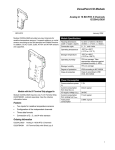
1
Inline terminal: 2 resistive temperature sensor inputs ILT TEMP 2 RTD Device description Preliminary Disclaimer / Imprint This manual is intended to provide support for installation and usage of the device. The information is believed to be accurate and reliable. However, SysMik GmbH Dresden assumes no responsibility for possible mistakes and deviations in the technical specifications. SysMik GmbH Dresden reserves the right to make modifications in the interest of technical progress to improve our modules and software or to correct mistakes. We are grateful to you for criticism and suggestions. Further information (device description, available software) can be found on our homepage www.sysmik.de. Please ask for latest information. SysMik disclaims all warranties in case of improper use or disassembly and software modifications not described in this document or when using improper or faulty tools. Commissioning and operation of the device by qualified personnel only. All applicable regulations have to be observed. SysMik® and the SysMik logo are registered trademarks of SysMik GmbH Dresden. IPOCS™ is trademark © of SysMik GmbH Dresden. "Networking Together!" is subject to copyright of SysMik GmbH Dresden. All other trademarks mentioned in this document are registered properties of their owners. These and further trademarks are used in this document but not marked for better readability. No part of this document may be reproduced or modified in any form without prior written agreement with SysMik GmbH Dresden. Copyright © 2014 by SysMik GmbH Dresden SysMik GmbH Dresden Tel + 49 (0) 351 – 4 33 58 – _0 Bertolt-Brecht-Allee 24 Fax + 49 (0) 351 – 4 33 58 – 29 01309 Dresden E-Mail (Sales) E-Mail (Support) Germany 2 Homepage sysmik.de [email protected] [email protected] www.sysmik.de ILT TEMP 2 RTD Contents Contents Device description 1 Contents 3 1 Description 4 2 Order information 4 3 Technical data 5 4 Local diagnostic and status indicators / Terminal point assignment 7 5 Internal circuit diagram 8 6 Electrical isolation 8 7 Connection notes 9 8 Connection examples 10 9 Measuring ranges 11 9.1 Measuring Ranges Depending on the Resolution (Format IB Standard) 11 9.2 Input measuring values 11 10 Measuring errors 10.1 Systematic measuring errors during temperature measurement using resistance thermometers 12 10.2 Systematic errors during temperature measurement using 2-wire technology 13 11 Tolerance and temperature response ILT TEMP 2 RTD 12 sysmik.de 15 3 Description / Order information 1 Description Note: This device description is only valid in association with the IL SYS INST UM user manual or the Inline system manual of the specifically used bus system. Make sure you always use the latest documentation – it can be downloaded at www.sysmik.de. The terminal is designed for use within an -Inline station. This terminal provides an two-channel input module for resistive temperature sensors. This terminal supports platinum and nickel sensors according to the DIN standard and the SAMA guideline. In addition, sensors Cu10, Cu50, Cu53 as well as KTY81 and KTY84 are supported. The measuring temperature is represented by 16-bit values in two process data words (one word per channel). Features Two inputs for resistive temperature sensors Configuration of channels via the bus system Measured values can be represented in three different formats Connection of sensors in 2, 3, and 4-wire technology 2 Order information Description Type Part No. Pcs./Pkt. Inline terminal with two resistive temperature sensor inputs, complete with accessories (connector and labeling field) ILT TEMP 2 RTD 1225-100519-01-9 1 4 sysmik.de ILT TEMP 2 RTD Technical data 3 Technical data General data Housing dimensions (width x height x depth) 12.2 mm x 120 mm x 66.6 mm Weight 46 g (without connector); 67 g (with connector) Operating mode Process data mode with 2 words Connection method for sensors 2, 3 and 4-wire technology Ambient temperatures (operation) -25 °C to +55 °C Ambient temperature (storage/transport) -25 °C to +85 °C Permissible humidity (operation/storage/transport) 10 % to 95 %, according to DIN EN 61131-2 Permissible air pressure (operation/storage/transport) 70 kPa to 106 kPa (up to 3000 m above see level) Degree of protection IP20 according to IEC 60529 Class of protection Class 3 according to EN 61131-2, IEC 61131-2 Connection data for Inline connectors Connection type Spring-cage terminals Conductor cross-section 0,2 mm² to 1,5 mm² (solid or stranded), AWG 24 - 16 Interface Local bus Data routing Power Consumption Communications power UL 7.5 V Current consumption at UL 43 mA (typical), 60 mA (maximum) I/O supply voltage UANA 24 V DC Current consumption at UANA 11 mA (typical), 18 mA (maximum) Total power consumption 587 mW (typical), 882 mW (maximum) Supply of the Module Electronics and I/O Through the Bus Coupler/Power Terminal Connection method Potential routing Analog Inputs Number Two inputs for resistive temperature sensors Connection of the signals 2, 3 or 4-wire, shielded sensor cable Sensor types that can be used Pt, Ni, Cu, KTY Characteristics standards According to DIN/according to SAMA Conversion time of the A/D converter 120 µs, typical Process data update Depending on the connection method Both channels in 2-wire technology 20 ms One channel in 2-wire technology/one channel in 4wire technology 20 ms Both channels in 3-wire technology 32 ms ILT TEMP 2 RTD sysmik.de 5 Technical data none Safety equipment Electrical Isolation Common Potentials 24 V main voltage UM, 24 V segment voltage US, and GND have the same potential. FE is a separate potential area. Separate Potentials in the Terminal Test Distance Test Distance 7.5 V supply (bus logic) / 24 V analog supply (analog I/O) 7.5 V supply (bus logic) / 24 V analog supply (analog I/O) 7.5 V supply (bus logic) / functional earth ground 7.5 V supply (bus logic) / functional earth ground 24 V analog supply (analog I/O) / functional earth ground 24 V analog supply (analog I/O) / functional earth ground Error Messages to the Higher-Level Control or Computer System Failure of the internal voltage supply Yes Failure of or insufficient communications power UL Yes, I/O error message sent to the bus coupler 6 sysmik.de ILT TEMP 2 RTD Diagnostic and status indicators / Terminal point assignment 4 Local diagnostic and status indicators / Terminal point assignment Functional identification: green Local diagnostic and status indicators Designation Color Meaning D green Diagnostics Terminal point assignment for 2/3-wire termination: Terminal point Signal Assignment 1.1 I1+ RTD of sensor 1 1.2 I1- Constant current supply 1.3 U1- Measuring input of sensor 1 2.3 U2- Measuring input of sensor 2 2.1 I2+ RTD of sensor 2 2.2 I2- Constant current supply 1.4, 2.4 Shield Shield connection (channel 1 and 2) Terminal point assignment for 4-wire termination on channel 1 and 2-wire termination on channel 2: Fig. 1: Terminal point Signal Assignment 1.1 I1+ RTD of sensor 1 1.2 I1- Constant current supply 1.3 U1- Measuring input of sensor 1 2.3 U1+ Measuring input of sensor 2 2.1 I2+ RTD of sensor 2 2.2 I2- Constant current supply 1.4, 2.4 Shield Shield connection (channel 1 and 2) local diagnostic and status indicators and terminal point assignment Safety note: WARNING: During configuration, ensure that no isolating voltage is specified between the analog inputs and the local bus. During thermistor detection this, for example, means that the user has to provide signals with safe isolation, if applicable. Installation instruction: High current flowing through potential jumpers UM and US leads to a temperature rise in the potential jumpers and inside the terminal. To keep the current flowing through the potential jumpers of the analog terminals as low as possible, always place the analog terminals after all the other terminals at the end of the main circuit (sequence of the Inline terminals: see also IL SYS INST UM E user manual or the Inline system manual for your bus system). ILT TEMP 2 RTD sysmik.de 7 Circuit diagram / Electrical isolation 5 Internal circuit diagram Key: Protocol chip Optocoupler Mikroprocessor with multiplexer and analog/digital converter Electrically erasable programmable read-only memory DC/DC converter with electrical isolation Reference voltage Amplifier Fig. 2: Internal wiring oft terminal points Note: Other symbols used are explained in the IL SYS INST UM E user manual or in the Inline system manual for your bus system. 6 Electrical isolation Fig. 3: Electrical isolation of the individual function areas 8 sysmik.de ILT TEMP 2 RTD Connection notes 7 Connection notes Connection oft the resistance sensors: In 4-wire technology a sensor can only be connected to channel 1. In this case the sensor can only be connected to channel 2 using 2-wire technology. Shield connection: The Connection examples show how to connect the shield. Connect the shielding to the Inline terminal using the shield connection clamp. The clamp connects the shield directly to FE on the terminal side. Additional wiring is not necessary. Isolate the shield at the sensor. Sensor connection in 4-wire technology: Always connect temperature shunts using shielded, twisted-pair cables. ILT TEMP 2 RTD sysmik.de 9 Connection examples 8 Connection examples Connection of passive sensors A Channel 1; 2- wire technology A Channel 1; 4-wire technology B Channel 2; 3- wire technology B Channel 2; 2-wire technology Fig. 4: Connection of sensors in 2 and 3-wire technology with shield connection Fig. 5: Connection of sensors in 4 and 2-wire technology with shield connection When connecting the shield at the terminal you must insulate the shield on the sensor side (shown in gray in Figure 4 and Figure 5). Use a connector with shield connection when installing the sensors. Figure 4 shows the connection schematically (without shield connector). Connection of a potentiometer 1) Connection and direct %-evaluation of a 2-kΩ potentiometer at channel 1 in 2-wire technology 2) Connection and direct %-evaluation of a 2-kΩ potentiometer at channel 1 in 3-wire technology Fig. 6: Fig. 7: 10 Connection of a potentiometers at channel 1 in 2-wire technology with shield connection sysmik.de Connection of a potentiometers at channel 1 in 3-wire technology with shield connection ILT TEMP 2 RTD Measuring ranges 9 Measuring ranges 9.1 Measuring Ranges Depending on the Resolution (Format IB Standard) Resolution (Bit 7 and 6) Temperature sensors 00 -273 °C up to +3276,8 °C resolution: 0,1 °C 01 -273 °C up to +327,68 °C resolution: 0,01 °C Where: 10 -459 °F up to +3276.8 °F resolution ung: 0,1 °F T [°C] … Temperature in °C 11 -459 °F up to +327.68 °F resolution: 0,01 °F 9.2 No. Temperature values can be converted from °C to °F according to the following formula: T [°F] … Temperature in °F Input measuring values Input Sensor type Measuring range (Software-supported) Lower limit 0 Pt R0 10 Ω to 3000 Ω acc. to DIN -200 °C +850 °C 1 Pt R0 10 Ω to 3000 Ω acc. to SAMA -200 °C +850 °C 2 Ni R0 10 Ω to 3000 Ω acc. to DIN -60 °C +180 °C 3 Ni R0 10 Ω to 3000 Ω acc. to SAMA -60 °C +180 °C 4 Cu10 -70 °C +500 °C 5 Cu50 -50 °C +200 °C 6 Cu53 -50 °C +180 °C 7 Ni1000 L+G -50 °C +160 °C 8 Ni500 (Viessmann) -60 °C +250 °C 9 KTY81-110 -55 °C +150 °C 10 KTY84 -40 °C +300 °C 11 Temperature sensors Upper limit Reserved 12 13 Relative potentiometer range 0% 4 kΩ / R0 x 100 % (max. 400 %) 14 Linear resistance measuring range 0Ω 400 Ω 0 Ω 4000 Ω 15 ILT TEMP 2 RTD sysmik.de 11 Measuring errors 10 Measuring errors 10.1 Systematic measuring errors during temperature measurement using resistance thermometers When measuring temperatures using resistance thermometers, systematic measuring errors are often the cause of incorrectly measured results. There are three possibilities of connecting sensors: 2, 3, and 4-wire technology. 4-Wire technology 3-Wire technology 4-wire technology is the most precise way of measuring (see Fig.8) Fig. 8: Connection of resistance thermometers in 4-wire technology When using the 4-wire technology, a constant current is sent through the sensor via cables I+ and I-. With the other two cables U+ and U-, the temperature-related voltage is tapped and measured at the sensor. The cable resistances do not influence the measurement. 12 Fig. 9: Connection of resistance thermometers in 3-wire technology In 3-wire technology the effect of the cable resistance on the measured result within the terminal is eliminated or minimized by multiple measuring of the temperaturerelated voltage and corresponding calculations. The quality of the results is almost as good as when using the 4wire technology shown in Fig. 8. However, the 4-wire technology provides better results in environments subject to heavy noise. sysmik.de ILT TEMP 2 RTD Measuring errors 2-Wire technology 2-wire technology is the most cost-effective connection method. The U+ and U- cables are no longer needed. Temperature-related voltage is not directly measured at the sensor and therefore not falsified by the two cable resistances RL (Fig. 10). The measuring errors that occur may lead to the entire measurement to become useless (diagrams in Fig. 11 to Fig. 13). However, these diagrams show at which points of the measurement system measures can be taken to minimize these errors. Bild 10: Connection of resistance thermometers in 2-wire technology 10.2 Systematic errors during temperature measurement using 2-wire technology Curves depending on the cable cross section A Fig. 11: Systematic temperature measuring error ΔT depending on the cable length l (1) Temperature measuring error for A = 0,14 mm² (2) Temperature measuring error for A = 0,25 mm² (3) Temperature measuring error for A = 0,50 mm² (Measuring error valid for: 2 copper cable χ = 57 m/Ωmm , TA= 25°C and Pt100 sensor) (Measuring error valid for: 2 copper cable χ = 57 m/Ωmm , TA= 25°C, l = 5 m and Pt100 sensor) Fig. 12: Systematic temperature measuring error ΔT depending on the cable cross section A Measuring error valid for: copper cable χ = 57 m/Ωmm2, l = 5 m, A = 0.25 mm2, and Pt100 sensor) Fig. 13: Systematic temperature measuring error ΔT depending on the cable temperature TA ILT TEMP 2 RTD sysmik.de 13 Measuring errors All diagrams show that the increase in cable resistance causes the measuring error. A considerable improvement is made through the use of Pt1000 sensors. Due to the 10-fold higher temperature coefficient α (α = 0.385 Ω/K for Pt100 to α = 3.85 Ω/K for Pt1000) the effect of the cable resistance on the measurement is decreased by factor 10. All errors in the diagrams above would be reduced by factor 10. Diagram 1 clearly shows the effect of the cable length on the cable resistance and therefore on the measuring error. The solution is to use the shortest possible sensor cables. Diagram 2 shows the influence of the cable diameter on the cable resistance. It can be seen that cables 2 with a cross section of less than 0.5 mm cause errors to increase exponentially. Diagram 3 shows the effect of the ambient temperature on the cable resistance. This parameter does not play a great role and can hardly be influenced but it is mentioned here for the sake of completeness. The formula to calculate the cable resistance is as follows: Where: RL Cable resistance in Ω RL20 Cable resistance at 20 °C in Ω l Cable length in m χ Specific electrical resistance of cop2 perin Ωmm /m A Cable cross-section in mm 2 0,0043 1/K Temperature coefficient for Kupfer TA Ambient temperature ( cable temperature) in °C Since there are two cable resistances in the measuring system (forward and return), the value must be doubled. The absolute measuring error in Kelvin [K] is provided for platinum sensors according to DIN using the average temperature coefficient α (α = 0.385 Ω/K for Pt100; α = 3.85 Ω/K for Pt1000). 14 sysmik.de ILT TEMP 2 RTD Tolerance and temperature response 11 Tolerance and temperature response α: Medium sensitivity to calculate the tolerance values. x: Additional error when the connection is made using 2-wire technology (see Systematic errors during temperature measurement using 2-wire technology). Typical measuring tolerances at 25°C α at 100 °C 2-Wire technology 3-Wire technology 4-Wire technology relative [%] absolute relative [%] absolute relative [%] absolute Temperature sensors Pt100 0,385 Ω/K ±0,03 + x ±0,26 K + x ±0,03 ±0,26 K ±0,02 ±0,2 K Pt1000 3,85 Ω/K ±0,04 + x ±0,31 K + x ±0,04 ±0,31 K ±0,03 ±0,26 K Ni100 0,617 Ω/K ±0,09 + x ±0,16 K + x ±0,09 ±0,16 K ±0,07 ±0,12 K Ni1000 6,17 Ω/K ±0,11 + x ±0,2 K + x ±0,11 ±0,2 K ±0,09 ±0,16 K Cu50 0,213 Ω/K ±0,24 + x ±0,47 K + x ±0,24 ±0,47 K ±0,18 ±0,35 K Ni1000 L+G 5,6 Ω/K ±0,13 + x ±0,21 K + x ±0,13 ±0,21 K ±0,11 ±0,18 K Ni500 Viessmann 2,8 Ω/K ±0,17 + x ±0,43 K + x ±0,17 ±0,43 K ±0,14 ±0,36 K KTY81-110 10,7 Ω/K ±0,07 + x ±0,11 K + x ±0,07 ±0,11 K ±0,06 ±0,09 K KTY84 6,2 Ω/K ±0,06 + x ±0,19 K + x ±0,06 ±0,19 K ±0,05 ±0,16 K 0 Ω bis 400 Ω ±0,025 + x ±100 mΩ + x ±0,025 ±100 mΩ ±0,019 ±75 mΩ 0 Ω bis 4 kΩ ±0,03 + x ±1,2 Ω + x ±0,03 ±1,2 Ω ±0,025 ±1 Ω Linear resistance ILT TEMP 2 RTD sysmik.de 15 Tolerance and temperature response Maximum measuring tolerances at 25°C α at 100 °C 2-Wire technology 3-Wire technology 4-Wire technology relative [%] absolute relative [%] absolute relative [%] absolute Temperature sensors Pt100 0,385 Ω/K ±0,12 + x ±1,04 K + x ±0,12 % ±1,04 K ±0,10 % ±0,83 K Pt1000 3,85 Ω/K ±0,15 + x ±1,3 K + x ±0,15 % ±1,3 K ±0,12 % ±1,04 K Ni100 0,617 Ω/K ±0,36 + x ±0,65 K + x ±0,36 % ±0,65 K ±0,29 % ±0,52 K Ni1000 6,17 Ω/K ±0,45 + x ±0,81 K + x ±0,45 % ±0,81 K ±0,36 % ±0,65 K Cu50 0,213 Ω/K ±0,47 + x ±0,94 K + x ±0,47 % ±0,94 K ±0,38 % ±0,75 K Ni1000 L+G 5,6 Ω/K ±0,56 + x ±0,89 K + x ±0,56 % ±0,89 K ±0,44 % ±0,71 K Ni500 Viessmann 2,8 Ω/K ±0,72 + x ±1,79 K + x ±0,72 % ±1,79 K ±0,57 % ±1,43 K KTY81-110 10,7 Ω/K ±0,31 + x ±0,47 K + x ±0,31 % ±0,47 K ±0,25 % ±0,37 K KTY84 6,2 Ω/K ±0,27 + x ±0,81 K + x ±0,27 % ±0,81 K ±0,22 % ±0,65 K 0 Ω bis 400 Ω ±0,10 + x ±400 mΩ + x ±0,10 % ±400 mΩ ±0,08 % ±320 mΩ 0 Ω bis 4 kΩ ±0,13 + x ±5 Ω + x ±0,13 % ±5 Ω ±0,10 % ±4 Ω Linear resistance All errors indicated as a percentage are related to the positive measuring range final value. The maximum tolerances contain the theoretical maximum possible tolerances. The data refers to nominal operation (installation on horizontal mounting rail, US = +24 V). Please also observe the values for temperature drift and the tolerances under EMI influences. Temperature response at -25 °C to +55 °C 2, 3, 4-wire technology typical maximum ±12 ppm/°C ±45 ppm/°C Additional tolerances influenced by electromagnetic fields Type of Electromagnetic Interference Typical Deviation From the Measuring Range Final Value Criterion Electromagnetic fields; field strength 10 V/m according to EN 61000-4-3 / IEC 61000-4-3 < ±1,51 % A Conducted interference Class 3 (test voltage 10 V) according to EN 61000-4-6 / IEC 61000-4-6 < ±0,92 % A Fast transients (burst) Class 3 according to EN 61000-4-4 / IEC 61000-4-4 < ±0,24 % A 16 sysmik.de ILT TEMP 2 RTD