1
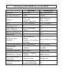
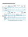
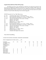
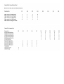
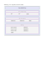
National Centre for Radio Astrophysics Tata Institute of Fundamental Research, Pune University Campus, Pune, INDIA Technical Report On The New Monitor and Control Module for GMRT Antennas By Charu Kanade, Naresh Sisodiya GMRT – TIFR, Khodad Email : cpk, naresh @gmrt.ncra.tifr.res.in Under The Guidance Of R. Balasubramaniam Group Coordinator Operations Group GMRTTIFR, Khodad GMRT – TIFR 30 / 11 / 2012 Acknowledgement We would like to avail this opportunity to express our heartfelt gratitude towards our reporting officer Shri R.Balasubramaniam, Group coordinator, Operations group, GMRT., for his constant guidance and encouragement. Being a key person in bringing up Operations group activities, he had a very clear idea of the objectives to be attained and guided us with his rich practical experience. He has not only guided us through the project, but also bring best out of us while designing New MCM Card. He has always welcome new ideas, new approaches to design efficient hardware and software. He has encouraged us to develop software from the scratch rather than using any proprietary operating System for controlling new MCM Card. The motive was to have entire control in our hand and making New MCM software very secure while putting it into network. We are also thankful to Ms. Nimisha Kanthariya and Mr. S Nayak for their support and guidence. Moreover we are thankful to Shri Raj Uprade, for his advice on New MCM Software development. We also express our gratitude towards Shri C Sathees and Shri Mahadeo Misal, for their invaluable help in building prototype boards and testing of New MCM card. We would like to say sincere thanks to RFI group for measuring radiation from the prototype MCM card and the final version of MCM card. We are also thankful to GMRT Front End group, IF LO group for their support while testing New MCM with their system. While working on New MCM card development project, scientific, technical and non technical staff has helped us in many ways. We take this opportunity to convey our thanks to them. Index • Introduction • New MCM Hardware Architecture • New MCM software architecture • Advantages of New MCM over old MCM • List of inputs received from other groups for configuring the New MCM • New MCM testing software – MTest • Reference Introduction New Monitoring and Controlling Module – New MCM is the general purpose card, designed using RCM4300 core module as processing unit. It has a motherboard, on which hardware for Multiplexing, Signal conditioning Digital data latching and serial communication is placed. On top of the motherboard, RCM4300 as daughterboard is placed. New MCM will be directly interfaced with other systems of GMRT like Front End, Fiber Optics, Analog Back End, Sentinel etc. New MCM will monitor as well as control the various parameters of such systems. It will also generate the alarm in the erroneous condition and it will take immediate precautionary action. As compared to existing MCM, this New MCM is more powerful in terms of computing power, operating frequency, memory and the other features. Moreover it is more intelligent in terms of its software capabilities and command structure. As New MCM is more powerful than previous one, most of the higher level intelligence has been shifted from Online and ABCCOM software to New MCM card. In this document we have explained Hardware and Software architecture of New MCM. Also comparison between New MCM and existing MCM is made to show how New MCM supersedes the existing one. Motivation for changing the old MCM : It has been 15 years since last MCM was designed, during that technology has been advanced dramatically. Now a days we have more powerful processors interms of bits as well as operating frequency. To keep pace with new technology and next generation Online system we need more powerful hardware at every stage. Also we wanted to provide more functionalities in terms of processing power, communication channels, monitoring channels, controlling channels, intelligent command structure, data storage etc. In short we wanted to make it more and more powerful to support requirement of Online as well as other GMRT subsystems with which New MCM will be interfaced. Criteria for designing New MCM Card : The design criteria for New MCM is as follows : • • • • • • • • Software development using higher level language Ethernet Support Serial as well as SPI interface support Low EMI from card Onboard data storage 64 analog monitoring channels Monitoring signal range : +/ 5V. 32 TTL compatible output channels Criteria for using RCM 4300 and Rabbit4000 processor : Nowadays Embedded Development Kits includes all the tools necessary to complete embedded network design, including a world class IDE, Graphical Debugger, Real Time Operating System, and TCP/IP Stack. Every kit includes Integrated peripherals include 10/100 Ethernet, SPI Bus and/or CAN Bus, A/D inputs, PWM outputs, USB and more. The available options for Embedded Development Kits were from companies like Rabbit Semi conductor, NetBurner, PIC etc. As far as hardware features and price is concerned, most of them are equal. The Rabbit Core Module 4300 has few advantages over others. • “Dynamic C” IDE for software development, that supports cooperative multitasking with C language. • On board Ethernet Hardware. • Inbuilt EMI reduction hardware and software control, called as the Spectrum Spreader which reduces EMI by 10dB. • More General purpose I/O pins are available for design to the user. • The GPIO pins have upto FOUR multi function feature. • Rabbit semiconductor offers variety of products and long term support. The rabbit processor series Rabbit 2000,3000,4000,5000 are still in use. New MCM Hardware Architecture New MCM hardware has been built around powerful rabbit core module RCM 4300, which has Rabbit4000 processor on board. New MCM has been designed using Altium Designer 6.7 software. The PCB is double layered which includes four 16X1 multiplexing, Signal conditioning to convert +/5V to 05V, RS485 Serial Communication, 2 SPI ports and 32 bits Data latching. Most of the components are SMD to make New MCM very compact. Above figure shows block diagram of Hardware architecture of the New MCM. Block diagram has been described below. RCM 4300 Core Module : The RCM4300 series of RabbitCore modules is one of the next generation of core modules that take advantage of new Rabbit 4000 features such as hardware DMA, clock speeds of up to 60 MHz, I/O lines shared with up to six serial ports and four levels of alternate pin functions that include variablephase PWM, auxiliary I/O, quadrature decoder, and input capture. Coupled with more than 500 new opcode instructions that help to reduce code size and improve processing speed, this equates to a core module that is fast, efficient, and the ideal solution for a wide range of embedded applications. The RCM4300 also features an integrated 10/100BaseT Ethernet port, an optional A/D converter, and removable (“hotswappable”) memory cards. The RCM4300’s massstorage capabilities make them suited to running the optional Dynamic C FAT file system module where data are stored and handled using the same directory file structure commonly used on PCs. A removable microSD™ Card can be hot swapped to transfer data quickly and easily using a standardized file system. Description of Rabbit 4000 processor : The Rabbit Semiconductor has designed the Rabbit 2000, the Rabbit 3000 the Rabbit 4000 and the Rabbit 5000 microprocessors for use in small and mediumscale singleboard computers over period of time. The Rabbit 2000, the Rabbit 3000 do not support Ethernet port and SPI Bus. The Rabbit 5000 supports 10/100BaseT and 802.11b/g WiFi network interfaces and CPU clock frequency of 100 MHz. But WiFi network interface makes it unsuitable for use in New MCM card. The Rabbit 4000 is a 8bit highperformance microprocessor with low electromagnetic interference (EMI), and is designed specifically for embedded control, communications, and Ethernet connectivity. Extensive integrated features and glueless architecture facilitate rapid hardware design, while a C friendly instruction set promotes efficient development of even the most complex applications. The Rabbit 4000 is fast, running at up to 60 MHz, with compact code and support for up to 16 MB of memory. Operating with a 1.8 V core and 3.3 or 1.8 V I/O, the Rabbit 4000 boasts an internal 10BaseT Ethernet interface, eight channels of DMA, six serial ports with IrDA, 40+ digital I/O, quadrature decoder, PWM outputs, and pulse capture and measurement capabilities. It also features a battery – backed realtime clock, glueless memory and I/O interfacing, and ultralow power modes. Four levels of interrupt priority allow fast response to realtime events. Its compact instruction set and high clock speeds give the Rabbit 4000 exceptionally fast math, logic, and I/O performance. Analog Multiplexer : The 64 input monitoring signals are handled by FOUR, 16 to 1 Analog multiplexers. Outputs of the FOUR multiplexer are connected to four input pins of 8 channel ADC . Level Shifter Circuit : The input voltage range of ADC used on RCM 4300 is from 0 V to +2V. The Level shifter circuit maps input signal voltage range of +/ 5 V to 0 to 2 V. 32 bit Output Port : The 32 output lines of Output Port are TTL compatible for interacting with GMRT subsystems. All output lines are latched before appearing on output Connector. Ethernet Interface : New MCM has got an integrated 10/100 BasedT Ethernet Port. Serial Interface : To support existing GMRT subsystems the Serial Interface at baud rate of 9600 bps. It supports RS485 in Half Duplex, multidrop mode, differential transmission line. SPI Bus : The New MCM card supports SPI Bus to interface with FSW based new LO system. The SPI Bus speed is 200 Kbps. Two SPI ports are provided on the MCM card. New MCM Software Architecture New MCM software has been developed from the scratch using dynamic C, which supports cooperative multitasking. It uses the infinite while loop approach instead of using the OS. Moreover, the New MCM software has been designed carefully, so it can include all necessary features and exhibit good performance. Software architecture of New MCM supports the Communication over the Ethernet as well as Serial link, 64 channel monitoring, 32 bit controlling, up to 1Gb data storage using FAT16 file system. Furthermore, it will have Real Time Clock and Web server running inside. • Main Application or Master loop takes care of entire new MCM software, it handles all the parallel tasks to be done by New MCM, like to establish connection with remote device, listen for command over either Ethernet or serial link, to do background monitoring, to serve web pages etc. • Client/Server running inside new MCM establishes socket connection with Server/Client running on remote PC on particular port address. • System specific input/output modules looks at received command, It looks for the ▪ System name like ; IF, LO, FE, Sentinel etc. ▪ Operation to be performed like ; Set, Monitor Raw data/Summery ▪ Parameters to be set like ; Attenuation, Bandwidth, LO frequency, Filter selection etc ▪ Arguments to the parameters • Monitoring system parameters actually performs the monitoring task by running the ADC operations. First raw data is generated by scanning all 64 monitoring channels. Summery is prepared based on gathered raw data. Raw count 0 is generated for +5V, 1000 for 0V and 2000 for 5V. • Set system parameters generates 32 bit patterns for setting the system specific parameters. Unlike old MCM, New MCM has inbuilt logic that reads the intelligent command and internally generates 32 bit pattern rather then receiving it from higher level application. • Data storage modules stores monitoring data as well as keeps the log of command received and executed by MCM. FAT 16 filesystem is used to manage stored data in directories and files. • New MCM supports HTTP protocol so we can run web server on it. This can be useful to host web pages for monitoring and controlling of GMRT subsystems. We can put web pages that show current status of New MCM like RTC time, 64 channel raw data, local system summery etc. Moreover we can use such web pages for system debugging. The web pages provides very good user interface to set system parameters. For security reasons setting of parameter will support lab testing only. We have used HTML, CSS, JavaScript, XML and AJAX for web development. • RTC module reads as well as sets real time clock of New MCM. RTC is used for synchronizing MCM with higher level application. • TCP/IP stack is provided by Dynamic C. New MCM software calls library function of the TCP/IP stack for establishing socket communication between the New MCM and the higher level application at 10/100 Mbps Ethernet link. • Serial communication Module is used to do communication over serial link at 9600bps. It supports communication of New MCM with existing system over RS485 serial communication link. Moreover, Command structure for communication between MCM and higher level application is designed intelligently so that it can carry all the necessary information in one go and with minimum command length. Command are pure ASCII characters bound in command structure. Advantages of New MCM over existing MCM New MCM Existing MCM Processor Rabbit 4000 8051 based 80535 Operating Frequency 60MHz 3.6MHz Memory SRAM : 1Mb (512+512) Flash : 1Mb MicroSD : up to 1Gb RAM : 256 bytes ROM : 64 Kb ADC 11 bits; 8 channels 8 bits; 8 channels Real Time Clock Yes No Battery Backup Yes – 3.3V on board battery No Monitoring Channels 64 64 Control Bits 32 16 Communication Channels Serial (RS485) @ 9.8Kbps Ethernet @ 10/100Mbps 2 SPI ports Serial (RS485) @ 9.8Kbps Programming Method Serial programming EPROM burning Programming Language Dynamic C Assembly Command Structure ASCII based Protocol based MCM Address setting Hardware + Software IP based Hardware only Access from Online Application Direct or via ABC Via ABC only Configurable for RFI reduction Yes – using Spectrum spreader, Clock divider No List of inputs received from GMRT groups for configuring the MCM Input required from GMRT subsystems includes : • • • • • • • • Number of monitoring channels Mapping of monitoring points with 64 MCM channels Number of control channels Bit pattern to set system parameters Complete information about all parameters of particular system to be monitored and/or controlled Special command priority Number and types of argument to that Parameter Other Information, if any Inputs Received from Analog BackEnd group : Monitor Analog BackEnd Control bits : S – Synthesizer, Si – Signal generator, A – Antenna, N – Noise source, D – Direct, M – Mixer, 1 / 2 – Channel select Inputs Received from Optical Fiber group : Inputs Received from Front End group : The MCM card sitting in the common box should have 64 monitoring channels. The RF Control and Monitoring (RFCM) card located in the front end boxes which talk to the MCM through MCM Interface card located in the common box will have 32 monitoring channels per frequency band. At present we need only 16 bits to fully control our system. However it may be worth allocating 32 bits for future upgrade. MCM Channels for Front End Monitoring : 01 – 06 07 – 16 17 – 24 25 – 26 27 28 29 30 31 – 40 41 – 48 49 – 50 51 52 53 54 55 Serialized outputs from six front end boxes Band selector bit monitor (2 x 5) (0 to 3.4 Volts) (CH1) Solar Attenuator bit monitor (2 x 4) (0 to 3.4 Volts) (CH1) Channel swap monitor (1 X 2) (0 to 3.4 Volts) Monitor +VCC (CH1) Monitor –VCC (CH1) Monitor Vref (+1.7 Volts) (CH1) RF Power monitor (CH1) Band selector bit monitor (2 x 5) (0 to 3.4 Volts) (CH2) Solar Attenuator bit monitor (2 x 4) (0 to 3.4 Volts) (CH2) Channel swap monitor (1 X 2) (0 to 3.4 Volts) Monitor +VCC (CH2) Monitor –VCC (CH2) Monitor Vref (+1.7 Volts) (CH2) RF Power Monitor (CH2) Common box temperature monitor Front End Controlling : New MCM Testing Software – MTest To test various feature of new MCM we have developed New MCM Testing Software called MTest. Using this software we can test Ethernet communication, LO setting through SPI bus, setting 32 control bits and 64 monitoring channels. Mtest has been written in Dynamic C, and it can be loaded to New MCM via serial programming cable. MTest is web based test software, so user need only browser to test New MCM functionalities. New MCM can be put into network or it can be connected directly to PC. Each MCM has its own IP address, so to test New MCM user has to type IP address of MCM into address bar of the web browser to initiate testing. By default MCM serves Monitoring page which shows all 64 monitoring channels raw data & voltage information, system status and LO frequency. By clicking “SET New MCM” button user can navigate to setting page. At setting page user can set 32 digital bits, LO frequency through SPI bus and RFI testing parameters. As per users (like SigCon, Front End, Optical Fiber) requirement, this software will be modified in the next version. Following is the snapshot of monitoring window Following is the snapshot of control window : Reference Documents : • • • • • • • • Rabbit 4000 Microprocessor User's Manual RCM 4300 User's Manual Dynamic C User's Manual Dynamic C Function Reference Manual Dynamic C TCPIP User's Manual : Volume 1 RabbitWeb – Dynamic C TCPIP User's Manual : Volume 2 Dynamic C FAT File System GMRT MONITOR AND CONTROL MODULE SOFTWARE : Mukund Gadgil 1992 Books : • • • Programming in ANSI C – E Balagurusamy Embedded Ethernet and Internet Complete – Jan Axelson Unix Network Programming – Richard Stevens Web Sites : • • • • www.digi.com/products/wireless-wired-embedded-solutions/ www.ti.com/lit/an/sboa092a/sboa092a.pdf http://beej.us/guide/bgnet/output/html/multipage/index.html www.w3schools.com