1
OptoLyzer OL3025o
User’s Manual
UM_OptoLyzer_OL3025o_V02_00_XX-3.pdf
Nov. 2009
®
MOST
Media Oriented Systems Transport
Multimedia and Control
Networking Technology
Copyright © 2009 SMSC
*X13247*
OptoLyzer OL3025o
Legend
Copyright © 2009 SMSC. All rights reserved.
Please make sure that all information within a document marked as 'Confidential' or 'Restricted Access' is handled
solely in accordance with the agreement pursuant to which it is provided, and is not reproduced or disclosed to others
without the prior written consent of SMSC. The confidential ranking of a document can be found in the footer of every
page. This document supersedes and replaces all information previously supplied. The technical information in this
document loses its validity with the next edition. Although the information is believed to be accurate, no responsibility is
assumed for inaccuracies. Specifications and other documents mentioned in this document are subject to change without notice. SMSC reserves the right to make changes to this document and to the products at any time without notice.
Neither the provision of this information nor the sale of the described products conveys any licenses under any patent
rights or other intellectual property rights of SMSC or others. There are a number of patents and patents pending on
the MOST technology and other technologies. No rights under these patents are conveyed without any specific agreement between the users and the patent owners. The products may contain design defects or errors known as anomalies, including but not necessarily limited to any which may be identified in this document, which may cause the product
to deviate from published descriptions. Anomalies are described in errata sheets available upon request. SMSC products are not designed, intended, authorized or warranted for use in any life support or other application where product
failure could cause or contribute to personal injury or severe property damage. Any and all such uses without prior written approval of an officer of SMSC will be fully at your own risk. MediaLB, SMSC and MOST are registered trademarks
of Standard Microsystems Corporation ("SMSC") or its subsidiaries. Other names mentioned may be trademarks of
their respective holders.
SMSC disclaims and excludes any and all warranties, including without limitation any and all implied warranties of merchantability, fitness for a particular purpose, title, and against infringement and the like, and any and all warranties arising from any course of dealing or usage of trade. In no event shall SMSC be liable for any direct, incidental, indirect,
special, punitive, or consequential damages; or for lost data, profits, savings or revenues of any kind; regardless of the
form of action, whether based on contract; tort; negligence of SMSC or others; strict liability; breach of warranty; or otherwise; whether or not any remedy of buyer is held to have failed of its essential purpose, and whether or not SMSC
has been advised of the possibility of such damages.
User’s Manual
Page 2
Copyright © 2009 SMSC
UM_OptoLyzer_OL3025o_V02_00_XX-3.pdf
OptoLyzer OL3025o
User’s Manual
Copyright © 2009 SMSC
UM_OptoLyzer_OL3025o_V02_00_XX-3.pdf
Page 3
OptoLyzer OL3025o
User’s Manual Versions
Doc. Number
UM_OptoLyzer_OL3025o_V02_00_XX-3
Nov. 09
UM_OptoLyzer_OL3025o_V02_00_XX-2
Sep. 09
UM_OptoLyzer_OL3025oV2_00_XX-1
Sep. 08
User’s Manual
Page 4
Date
Copyright © 2009 SMSC
Description
Section 2: "and network status information"
added.
Section 2.1: New features added.
"and network status information" added.
Section 3.1.2: S/PDIF: Crossreference
added to Section 5.2.5.
Section 4.1: Hint added that mentions the
UpdateStickGenerator.exe
Section 4.4: Updating of the tools license
revised. Now the OptoLyzer Suite is used.
Section 5.2.2, Table 5-5: Numbering adapted
according to the Socket Protocol V1.3 user
manual, output added in table.
Hint added information can be found in the
user manual Socket Protocol V1.3.
New section about S/PDIF formats added:
Section 5.2.5
Table 3-1 in Section 3.1.1: Description
improved for Green Lock LED, booting operation (case 2).
First release User’s Manual
UM_OptoLyzer_OL3025o_V02_00_XX-3.pdf
OptoLyzer OL3025o
TABLE OF CONTENTS
1 PREFACE .................................................................................................................... 7
1.1 Intended Use .................................................................................................................................... 7
1.2 Scope of Delivery ............................................................................................................................. 7
1.2.1 Software on the CompactFlash ................................................................................................7
1.2.2 Software on the USB Stick ....................................................................................................... 7
1.3 Term Definitions ............................................................................................................................... 8
2 INTRODUCTION ......................................................................................................... 9
2.1 Features in Use with OptoLyzer OL3025o ....................................................................................... 9
2.2 Possible Scenario ........................................................................................................................... 10
2.2.1 Analyzing the MOST Network as Spy .................................................................................... 11
2.2.2 Performing Control Tasks ...................................................................................................... 11
3 INSTALLATION ......................................................................................................... 12
3.1 OptoLyzer OL3025o System Description ....................................................................................... 12
3.1.1 Front View of the OptoLyzer OL3025o ................................................................................... 12
3.1.2 Rear Panel of the OptoLyzer OL3025o .................................................................................. 15
3.2 Connectivity Diagram ..................................................................................................................... 17
3.2.1 Connectivity Diagram—Front Panel ....................................................................................... 17
3.2.2 Connectivity Diagram—Rear Panel ....................................................................................... 18
3.3 Booting the OptoLyzer OL3025o .................................................................................................... 19
4 MAINTENANCE ........................................................................................................ 20
4.1 Update All (Recommended Case) .................................................................................................. 20
4.2 Update CompactFlash .................................................................................................................... 21
4.3 Update MOST PC Interface Manually (DOS Tools) ....................................................................... 21
4.4 Update a License ........................................................................................................................... 22
5 TECHNICAL SPECIFICATION ................................................................................. 23
5.1 Mechanical and Environmental Characteristics ............................................................................. 23
5.1.1 Mechanical Dimensions ......................................................................................................... 23
5.1.2 Environmental Specification ................................................................................................... 23
5.2 Electrical Characteristics ................................................................................................................ 24
5.2.1 Power Supply ......................................................................................................................... 24
5.2.2 Trigger Interface ..................................................................................................................... 24
5.2.3 Audio Line IN/OUT ................................................................................................................. 25
5.2.4 Headphone OUT .................................................................................................................... 25
5.2.5 S/PDIF IN/OUT ...................................................................................................................... 25
5.2.5.1 S/PDIF (IN) to MOST ..................................................................................................... 25
5.2.5.2 MOST to S/PDIF (OUT) ................................................................................................. 25
APPENDIX A: REFERENCES ..................................................................................... 26
User’s Manual
Copyright © 2009 SMSC
UM_OptoLyzer_OL3025o_V02_00_XX-3.pdf
Page 5
OptoLyzer OL3025o
User’s Manual
Page 6
Copyright © 2009 SMSC
UM_OptoLyzer_OL3025o_V02_00_XX-3.pdf
OptoLyzer OL3025o
1 Preface
1.1 Intended Use
This SMSC product is intended to be used for developing, testing, or analyzing MOST® based multimedia
products and systems by persons with experience in developing multimedia devices.
The operation of this SMSC product is only admitted with original SMSC devices, e.g., provided power
supply.
1.2 Scope of Delivery
The OptoLyzer OL3025o is delivered with:
• OptoLyzer OL3025o
• User Manual (printed version)
• Power-supply
• Cables
• Accessories
Check your shipment for completeness. If you have any complaints direct them to [email protected] (Europe and Asia) or to [email protected] (America). Providing the delivery
note number eases the handling.
1.2.1 Software on the CompactFlash
The CompactFlash™ comes with:
• Microsoft® Windows® CE 5.0 as operating system
• Microsoft® Windows® CE loader
• Extended software with spy functionality, MOST drivers and specific services
1.2.2 Software on the USB Stick
The USB stick comes with a complete backup of the CompactFlash. In addition, maintenance utilities
(DOS Tools) are offered on the USB stick (described in Section 4.3 on page 21).
User’s Manual
Copyright © 2009 SMSC
UM_OptoLyzer_OL3025o_V02_00_XX-3.pdf
Page 7
OptoLyzer OL3025o
1.3 Term Definitions
For better understanding of the following chapters, this section provides explanation to special terms, used
in the description of the OptoLyzer OL3025o.
Term
Definition
This mode stands for a manual update of either the FPGA or chips of the MOST PC Interface.
Advanced Mode
It is performed using the delivered USB stick.
The connected laptop/PC is called client, additional or target PC. The OptoLyzer OL3025o is
Client
designated as host.
A software that is running on the client. It manages the communication with the OptoLyzer
Controlling Software OL3025o. The controlling software comprises both the handling of spied data and performing
control tasks.
This mode stands for an automatic update of the FPGA / chips of the MOST PC Interface. It is
Easy Mode
performed using the delivered USB stick.
EHC
External Host Controller
The OptoLyzer Suite is working with a common format. Therefore the incoming data is
Event
converted to Events.
The OptoLyzer OL3025o is designated as host. The connected laptop/PC is called client,
Host
additional or target PC.
INIC
Intelligent Network Interface Controller
MBI
Message Based Interface
oPHY
Optical Pyhsical Layer
OptoLyzer G2 3025o This product comprises OptoLyzer Suite and OptoLyzer OL3025o.
Hardware of the OptoLyzer G2 3025o. It will be connected into the MOST network. Afterwards
OptoLyzer OL3025o
it takes the data for further processing.
This is the software of the OptoLyzer G2 3025o. It covers the OptoLyzer Suite main window,
OptoLyzer Suite
Viewers, Recorders, Graphs and Watches. In addition, the Transceiver and the MOST
Interface Control can be started in the OptoLyzer Suite.
POF
Plastic optical fiber
S/PDIF
Sony/Philips Digital Interconnect Format
Table 1-1: Term Definitions
User’s Manual
Page 8
Copyright © 2009 SMSC
UM_OptoLyzer_OL3025o_V02_00_XX-3.pdf
OptoLyzer OL3025o
2 Introduction
The OptoLyzer OL3025o is a versatile hardware for debugging and analyzing Control, Packet data, and
network status information in a MOST25 optical network. It provides connection to the MOST25 optical
network via a MOST oPHY connector that is based on the Optical Physical Layer. When used in combination with the OptoLyzer Suite all data is transferred via an Ethernet connection to a PC running the installed
OptoLyzer Suite. The device is prepared to work in laboratory (stationary) environments (voltage range of
100 - 240 V DC transformed to 12 V). The OptoLyzer OL3025o is able to run in timing master mode, slave
mode, bypass mode and S/PDIF master mode.
2.1 Features in Use with OptoLyzer OL3025o
Depending on the currently loaded firmware the OptoLyzer OL3025 features the following:
•
•
•
•
•
•
•
•
•
•
•
•
•
Versatile MOST network analysis tool for Control, Packet data and network status information
MOST25 network optical interface
SpyNIC for MOST25 running in bypass mode
StressNIC for MOST25
INIC running in bypass mode (default), in master or slave mode or as S/PDIF master. The INIC allows
sending and receiving of MOST Control and Packet data.
Remote connection via Ethernet interface
Routing of 4 MOST synchronous channels; respectively one to Line OUT, to Line IN, to S/PDIF OUT
and to S/PDIF IN
4 electrically isolated TTL hardware trigger
LEDs indicating different states of device and network
Support for 44.1 kHz and 48 kHz system sample rates and S/PDIF master
Time stamp resolution: ~1.3 µs; accuracy: 1 frame
Headphone interface
Boot Fallback (BFB) functionality
User’s Manual
Copyright © 2009 SMSC
UM_OptoLyzer_OL3025o_V02_00_XX-3.pdf
Page 9
OptoLyzer OL3025o
2.2 Possible Scenario
A MOST network might consist of various MOST devices. State-of-the-art multimedia systems need powerful tools for both finding of irregularities and controlling of the MOST network's interfaces. The OptoLyzer
OL3025o is developed to perform these tasks.
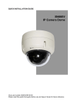
A possible scenario is depicted in Figure 2-1. The OptoLyzer OL3025o is part of the MOST network and
spies its data. The data is transmitted to a connected PC via an Ethernet connection. A controlling software (e.g., OptoLyzer Suite) handles the spied data. Triggering in both directions is possible. Additionally,
control tasks can be performed via a controlling software.
Figure 2-1: Possible Scenario of an OptoLyzer OL3025o
The following sections describe the concepts for both:
• Analyzing the MOST network as spy
And
• Performing control tasks (via e.g., OptoLyzer Suite)
User’s Manual
Page 10
Copyright © 2009 SMSC
UM_OptoLyzer_OL3025o_V02_00_XX-3.pdf
OptoLyzer OL3025o
2.2.1 Analyzing the MOST Network as Spy
The OptoLyzer OL3025o provides full spy functionality. Since the OptoLyzer OL3025o is always configured
as spy it has simply to be connected in a MOST network to use this feature. The OptoLyzer OL3025o spies
the complete traffic - even heavy data loads - on the Control data channel and the Packet data channel of
a MOST network. An included application takes the incoming data and converts it into a common format
named 'Events'. Another application provides a socket connection for further processing. If the OptoLyzer
OL3025o is used in combination with controlling software the spied data can be displayed in different kind.
E.g., the data can be monitored in a window for on-line analyzing. Furthermore the data can be shown in a
graph for statistic purposes. Even data recording is possible for off-line analyzing (see Figure 2-1). The
hardware trigger inputs allow injecting events via external hardware.
Note: For interpreting an acknowledge code it is important to know that the SpyNIC for
MOST25 is arranged behind the StressNIC and the INIC inside the OptoLyzer OL3025o.
2.2.2 Performing Control Tasks
The OptoLyzer OL3025o can also operate as timing master, slave or S/PDIF master. Then the OptoLyzer
OL3025o supports the performing of control tasks via controlling software on a client. For example the
mode of the OptoLyzer OL3025o can be changed. Normal operation assumed, messages can be sent and
viewed for e.g., test or simulation on the MOST network. In addition, the OptoLyzer OL3025o is able to
route streaming data.
User’s Manual
Copyright © 2009 SMSC
UM_OptoLyzer_OL3025o_V02_00_XX-3.pdf
Page 11
OptoLyzer OL3025o
3 Installation
This chapter describes the elements and connectors of the OptoLyzer OL3025o. A connectivity diagram
shows how to connect the OptoLyzer OL3025o and the client in a typical MOST network application.
3.1 OptoLyzer OL3025o System Description
The OptoLyzer OL3025o comes with all components configured and prepared for default operation. When
the OptoLyzer OL3025o is used in combination with the OptoLyzer Suite it needs to be connected to the
PC the application is running. The following sections describe the different views of the OptoLyzer
OL3025o. Service aspects as e.g., an update procedure are handled in Chapter 4 on page 20.
3.1.1 Front View of the OptoLyzer OL3025o
The front view of the OptoLyzer OL3025o provides access to external interfaces and elements for controlling and information.
Figure 3-1: OptoLyzer OL3025o (Front Panel)
The components are described from left to right:
Hardware Trigger Interface:
There are four hardware trigger that can be used as input or output. By default the hardware trigger are
specified as input trigger. In the spy operation mode the software will detect input hardware trigger
changes and send them over the Ethernet. For further technical details refer to Section 5.2 on page 24.
User’s Manual
Page 12
Copyright © 2009 SMSC
UM_OptoLyzer_OL3025o_V02_00_XX-3.pdf
OptoLyzer OL3025o
LEDs:
To the right of the hardware trigger interface there are three LEDs among each other. Each of them is supporting different functionalities depending on the operating mode. Normal operation means the OptoLyzer
OL3025o is ready i.e., the OptoLyzer OL3025o’s applications are running and an IP is available. The booting operation describes the time intervall from switching on the power of the OptoLyzer OL3025o until the
device is ready for operation. For more details on the booting process refer to Section 3.3 on page 19. In
the updating operation mode either the CompactFlash or the chips / FPGA of the OptoLyzer OL3025o are
updated or the license is updated. For more details on the updating process refer to Chapter 4 on page 20.
LED label
Color
State
On
R (Ready)
Red
Off
Blinking slowly
Blinking fast
On
M (Message) Yellow
Off
On
L (Lock)
Green
Off
Despription
1. Normal operation: The OptoLyzer OL3025o is ready.
2. Booting operation: Booting is completed. The OptoLyzer OL3025o is
ready.
3. Updating operation i.e., chips are in flashing mode if:
• Red and yellow LED are on simultaneously or
• Red, yellow and green LED are on simultaneously.
Although this can take a few minutes do not switch off the OptoLyzer
OL3025o in this state.
1. Normal operation: The OptoLyzer OL3025o is not ready. Services does
not work properly or there is no valid IP present on the device.
2. Booting operation: The OptoLyzer OL3025o is waiting for a valid IP.
3. Updating operation: Update is finished when red, yellow and green LED
are off simultaneously. Switch off, remove USB stick and switch on.
1. Normal operation: No function
2. Booting operation: The OptoLyzer OL3025o gets initialized.
3. Updating operation: No function
1. Normal operation: A twinkle command is sent from the OptoLyzer Suite.
2. Booting operation: The operating system is loaded.
1. Normal operation: A message is received by the INIC.
2. Booting operation: No function
3. Updating operation:
a. CompactFlash is updated.
•Only yellow LED is on.
b. Chips are in flashing mode if:
•Yellow and red LED are on simultaneously or
•Yellow, red and green LED are on simultaneously.
Although this can take a few minutes do not switch off the OptoLyzer
OL3025o in this state.
1. Normal operation: No function
2. Booting operation: No function
3. Updating operation: Update is finished when red, yellow and green LED
are off simultaneously. Switch off, remove USB stick and switch on.
1. Normal operation: The MOST network is locked.
2. Booting operation: The MOST network is locked.
3. Updating operation: If green, yellow and red LED are on simultaneously:
Chips are in flashing mode. Although this can take a few minutes do not
switch off the OptoLyzer OL3025o in this state.
The green LED is only on when either the SpyNIC for MOST25 or the
StressNIC or the INIC is updated. If the FPGA of the MOST PC Interface
is flashed the green LED is off.
1. Normal operation: The MOST network is not locked.
2. Booting operation: The MOST network is not locked.
3. Updating operation: Update is finished when red, yellow and green LED
are off simultaneously. Switch off, remove USB stick and switch on.
Table 3-1: Function of the Status LEDs
User’s Manual
Copyright © 2009 SMSC
UM_OptoLyzer_OL3025o_V02_00_XX-3.pdf
Page 13
OptoLyzer OL3025o
MOST Interface
The OptoLyzer OL3025o can be connected to the MOST network via a Yazaki 2+0 connector. The optical
parameters of the connector are compliant to the MOST Specification.
• Tx: Optical output for MOST network
• Rx: Optical input for MOST network
Audio Line IN and OUT:
The OptoLyzer OL3025o provides one audio input and one audio output connector to the right of the
MOST interface on its front panel. Each of them has a 3.5 mm plug. For technical details refer to
Section 5.2 on page 24.
Audio Headphone OUT:
The OptoLyzer OL3025o provides one audio headphones connector (3.5 mm plug) to the right of its front
panel. For technical details refer to Section 5.2 on page 24.
LED Power:
A green colored LED top right on the front panel indicates power is switched on.
Frequency LEDs:
The LEDs located on the right side indicate the frequency of the MOST network in all modes: timing master, slave, bypass and S/PDIF master. S/PDIF master means the OptoLyzer OL3025o is running in timing
master mode and it generates the frames for the entire MOST network synchronized to the incoming
S/PDIF source data stream. An external S/PDIF signal may have a tolerance of ± 100 Hz.
LED
44 kHz
48 kHz
S/PDIF
State
Description
The frequency of the MOST network is 44.1 kHz tolerating a deviation of ± 100 Hz.
The frequency of the MOST network is not 44.1 kHz.
The frequency of the MOST network is 48 kHz tolerating ± 100 Hz.
The frequency of the MOST network is not 48 kHz.
1. Only S/PDIF: The incoming S/PDIF source data stream has a frequency that is not
equal to 44.1 kHz or 48 kHz.
2. S/PDIF together with 44 kHz LED: The incoming S/PDIF source data stream has a
On
frequency of 44.1 kHz tolerating a deviation of ± 100 Hz.
3. S/PDIF together with 48 kHz LED: The incoming S/PDIF source data stream has a
frequency of 48 kHz tolerating a deviation of ± 100 Hz.
Blinking fast
S/PDIF master is set but the signal is not a valid S/PDIF signal.
1. S/PDIF master is not set: A S/PDIF signal is routed but it is not a valid S/PDIF signal.
2. S/PDIF master is set but the S/PDIF signal differs more than 100 Hz from 44.1 kHz or
48 kHz. This means if the S/PDIF signal is
Blinking slowly
• < 44 kHz or
• > 44.2 kHz and < 47.9 kHz or
• > 48.1 kHz.
Off
There is no incoming S/PDIF signal.
On
Off
On
Off
Table 3-2: Frequency LEDs
User’s Manual
Page 14
Copyright © 2009 SMSC
UM_OptoLyzer_OL3025o_V02_00_XX-3.pdf
OptoLyzer OL3025o
3.1.2 Rear Panel of the OptoLyzer OL3025o
The rear panel of the OptoLyzer OL3025o provides access to power jack, power switch, CompactFlash
slot, USB interfaces, a BFB button, and interfaces to a remote PC.
Figure 3-2: OptoLyzer OL3025o (Rear Panel)
All components of the rear panel are described from left to right and top down:
Power on/off Switch:
The power on/off switch is located left most. In position 'I' the OptoLyzer OL3025o is on, in position '0' the
power is switched off.
USB Interfaces (2x):
Designated only for connecting SMSC products as e.g., an USB stick for updating purposes or a WLAN
USB adapter.
Power Jack (mains):
The OptoLyzer OL3025o comes with an AC power supply unit (voltage range from 100 V to 240 V) that
has to be connected to this plug. For technical details refer to Section 5.2 on page 24.
Ethernet Interface:
This interface is the standard communication port that connects the OptoLyzer OL3025o to a PC via a
100Base-T Ethernet connection. If the OptoLyzer Suite is running on this PC it is able to control the OptoLyzer OL3025o and to receive its data. The connector is a standard RJ45. Left hand two LEDs give information on connection (Link LED: yellow) and traffic (Activity LED: green).
PS2 Interface (keyboard, mouse):
External interfaces are not needed neither for operating the OptoLyzer OL3025o nor for performing all
standard use cases. Nevertheless there is a PS2 interface for mouse and keyboard. It can be useful to
connect a mouse and a keyboard for more functionality. The mouse and the keyboard are not part of the
shipping.
User’s Manual
Copyright © 2009 SMSC
UM_OptoLyzer_OL3025o_V02_00_XX-3.pdf
Page 15
OptoLyzer OL3025o
CompactFlash Slot:
A CompactFlash slot is placed in the center of the rear panel. The delivered CompactFlash provides the
operating system Microsoft® Windows® CE 5.0 and all other software that is necessary for analyzing and
controlling purposes. To the right of the slot there is a small button to eject the CompactFlash.
S/PDIF OUT/IN
The OptoLyzer OL3025o provides respectively an optical S/PDIF output and input.
Connector types:
• S/PDIF OUT: TOTX173 (Toshiba)
• S/PDIF IN: TORX173 (Toshiba)
For more details on S/PDIF formats refer to Section 5.2.5 on page 25.
BFB Button:
This button provides a fallback solution if the update of an FPGA is interrupted (e.g., loss of power). Switch
off the OptoLyzer OL3025o. Then press the Boot Fallback button (BFB) for about 1 second and simultaneously switch on the OptoLyzer OL3025o.
VGA Interface:
The hardware of the OptoLyzer OL3025o supports a VGA interface for connecting a VGA monitor. The display will be recognized automatically. The enclosed adapter can be used for connecting a VGA monitor.
User’s Manual
Page 16
Copyright © 2009 SMSC
UM_OptoLyzer_OL3025o_V02_00_XX-3.pdf
OptoLyzer OL3025o
3.2 Connectivity Diagram
The following sections describe how the OptoLyzer OL3025o can be integrated in a MOST25 network. In
addition the connections are shown that are mandatory like the 100Base-T Ethernet connection to the laptop/PC running controlling software and the power supply. The MOST25 oPHY interface is mandatory for
analysis purposes. Furthermore some connections are mentioned that can be used for optional functionality like monitor, mouse, keyboard, and analog audio devices.
3.2.1 Connectivity Diagram—Front Panel
Figure 3-3 depicts the connectivity diagram of the front panel.
Figure 3-3: Connectivity Diagram—Front Panel
User’s Manual
Copyright © 2009 SMSC
UM_OptoLyzer_OL3025o_V02_00_XX-3.pdf
Page 17
OptoLyzer OL3025o
3.2.2 Connectivity Diagram—Rear Panel
The connectivity diagram of the rear panel is depicted in Figure .
* Optional
** There are several connection concepts how to connect a PC with the OptoLyzer. For details refer to the OptoLyzer
G2 3xxx Start-up Guide [2].
Figure 3-4: Connectivity Diagram—Rear Panel
User’s Manual
Page 18
Copyright © 2009 SMSC
UM_OptoLyzer_OL3025o_V02_00_XX-3.pdf
OptoLyzer OL3025o
3.3 Booting the OptoLyzer OL3025o
After connecting to the power supply the OptoLyzer OL3025o can be switched on. The red LED (R) to the
left of the MOST Interface indicates the progress while booting. The single steps are described in the
sequence as they occur.
1. The red LED blinks slowly: The OptoLyzer OL3025o starts initializing.
2. The red LED blinks fast: This indicates the operating system is loaded.
3. The red LED switches off: The operating system has been loaded and the OptoLyzer OL3025o is
waiting for a valid IP.
4. The red LED is on: All services are running and a valid IP is available. The OptoLyzer OL3025o is
ready to run.
User’s Manual
Copyright © 2009 SMSC
UM_OptoLyzer_OL3025o_V02_00_XX-3.pdf
Page 19
OptoLyzer OL3025o
4 Maintenance
The OptoLyzer OL3025o is shipped with a bootable USB stick. This chapter describes an automatically
performed update of both CompactFlash and MOST PC Interface (recommended case). In addition it is
possible to separately update the CompactFlash (Section 4.2) or the MOST PC Interface (Section 4.3).
4.1 Update All (Recommended Case)
The USB stick offers the possibility to automatically update the CompactFlash and the MOST PC Interface
(FPGA firmware, SpyNIC for MOST25, StressNIC and INIC) in one step. This option is the recommended
use case and is preset as default in the boot menu of the USB stick, i.e. this update procedure will be performed if not another option will be selected. Neither a keyboard nor a monitor need to be connected in the
default case. Only those parts (FPGA / chips) are updated for which newer versions are available.
Note: SMSC provides a utility called ’UpdateStickGenerator.exe’ that features the following:
- Automatical search for the recent firmware.
- Automatical download & storage of the recent firmware on a removable storage device.
The utility can be downloaded from our Web site. On the Web site search for
’UpdateStickGenerator’.
The update procedure is described below:
1. Switch off the OptoLyzer OL3025o.
2. Plug in the USB stick with the latest USB firmware that can be downloaded from SMSC AIS’s web site.
3. Switch on the OptoLyzer OL3025o.
The red LED (Ready) blinks slowly. After some seconds the red LED (R) stops blinking and the yellow
LED (M) turns on indicating the CompactFlash is updated. After some time the red LED (R) turns on
additionally. In this state the FPGA / chips are checked whether they have to be updated or not. If a
newer firmware is available the corresponding FPGA / chip will be flashed. Then the red, yellow and
green LED (except for an FPGA update) are on. The flashing procedure can take a few minutes
depending on the number of FPGA / chips to be updated.
Note: Do not switch off the OptoLyzer OL3025o during flashing the chips, i.e., while the
red, yellow and green LEDs are on.
After finishing the chip update, the LEDs turn off and finally the OptoLyzer OL3025 beeps once.
4. Power down the OptoLyzer OL3025o and remove the USB stick.
5. Switch on the OptoLyzer OL3025o. Because of the initialization caused by the update of the
CompactFlash the OptoLyzer OL3025o will boot twice. The red LED (R) indicates the progress:
1. Blinking slowly
2. Blinking fast
3. Blinking slowly
4. Blinking fast
5. Off
6. On
User’s Manual
Page 20
Copyright © 2009 SMSC
UM_OptoLyzer_OL3025o_V02_00_XX-3.pdf
OptoLyzer OL3025o
4.2 Update CompactFlash
The delivered USB stick contains a complete backup of the original CompactFlash data (factory default).
The CompactFlash can be recovered using the backup of the USB stick. The procedure how to recover the
CompactFlash is described below.
To recover or update the OptoLyzer OL3025o follow these steps:
1. Connect a keyboard, a monitor (not part of the shipment) and a mouse (optional) according Figure .
2. Plug in the delivered bootable USB stick into a USB slot.
3. Restart the OptoLyzer OL3025o.
The OptoLyzer OL3025o displays a boot menu.
Note: If no item is selected for some time (i.e., some seconds) the CompactFlash and the
PCI Board are updated automatically (described in Section 4.1 on page 20).
4.
5.
6.
7.
8.
Enter '1' for 'Update CompactFlash'.
Follow the instructions. The CompactFlash memory will be overwritten.
After finishing the recovery procedure switch off the OptoLyzer OL3025o.
Remove the USB stick.
Start the OptoLyzer OL3025o again by switching on the power. The OptoLyzer OL3025o will boot
twice as described in Section 4.1.
4.3 Update MOST PC Interface Manually (DOS Tools)
The USB stick allows to update the firmware of the chips manually. The procedure to achieve this with the
DOS tools is described below:
1. Connect a keyboard and a monitor (not part of the shipment).
2. Plug in the delivered bootable USB stick into a USB slot.
3. Restart the OptoLyzer OL3025o.
The OptoLyzer OL3025o displays a boot menu.
Note: If no item is selected for some time (i.e., some seconds) the CompactFlash and the
MOST PC Interface are updated automatically (described in Section 4.1 on page 20).
4. Enter '2' for 'Update MOST PC104+ Interface (DOS Tools)'.
5. Select the MOST PC Interface. Afterwards the following options are provided
• Check or Write License Keys
• Automatic update (easy mode)
• Manual update (advanced mode)
6. Select ’Manual update (advanced mode)’ and follow the instructions.
7. After finishing the update procedure switch off the OptoLyzer OL3025o.
8. Remove the USB stick.
9. Start the OptoLyzer OL3025o again by switching on the power.
For details how to use the DOS tools options please refer to the additional user manual DOS Tools MOST
PC Interfaces that can be found on the CD.
User’s Manual
Copyright © 2009 SMSC
UM_OptoLyzer_OL3025o_V02_00_XX-3.pdf
Page 21
OptoLyzer OL3025o
4.4 Update a License
If e.g., the customer purchased a new plugin for the OptoLyzer Suite it could be useful to update a license
(in this case the tool license). The tools license can be comfortably updated using the OptoLyzer G2 Admin
Web Interface implemented in the OptoLyzer Suite.
The procedure is described below:
1. Start the OptoLyzer Suite.
2. Right click in the main window and select ’Search’.
3. Select the OptoLyzer OL3025o (use the twinkle functionality to find the correct device) and confirm.
Afterwards the device will be shown in the main window.
4. Select the device in the main window.
5. Right click and select ’Configure’.
6. In the main menu select ’Tools License’. The current license is shown above an input field.
7. Enter the new license in the input field. You can find it on the application’s license card.
8. Click ’Set’.
The new license is written onto the OptoLyzer OL3025o V2. Now your new application can be started.
Note: The tools license can also be updated via the WIBU-Key Writer implemented in the
OptoLyzer Suite, via an MBI command that is described in the OptoLyzer Socket Protocol
[1] or via the DOS Tools available on the delivered USB stick.
User’s Manual
Page 22
Copyright © 2009 SMSC
UM_OptoLyzer_OL3025o_V02_00_XX-3.pdf
OptoLyzer OL3025o
5 Technical Specification
5.1 Mechanical and Environmental Characteristics
5.1.1 Mechanical Dimensions
Mechanical dimensions of the OptoLyzer OL3025o in millimeters, without screws, plugs and switches:
Height
50
Width
134
Depth
175
Table 5-1: Mechanical Dimensions of the OptoLyzer OL3025o
5.1.2 Environmental Specification
Protection against Over Temperature
The OptoLyzer OL3025o integrates temperature sensitive components. Therefore do not cover the device
with paper, textiles or other objects. Covering disables the passive cooling (cooling rips). Make sure to
allow enough airflow to the OptoLyzer OL3025o, when the device is assembled. Do never place the running OptoLyzer OL3025o in a closed case or box. Clean the surface of the computer system from dust, oil
and other isolating materials, to prevent a reduction of the cooling efficiency. Do not stack any OptoLyzer
OL3025o.
Operating Mode
Parameter
Ambient temperature
Relative humidity (non-condensing)
Values
0° to 50° C
80%
Table 5-2: Operating Mode
Non-Operating Mode (Storage)
Parameter
Ambient temperature
Relative humidity (non-condensing)
Values
-40° to 85° C
95%
Table 5-3: Non—Operating Mode
User’s Manual
Copyright © 2009 SMSC
UM_OptoLyzer_OL3025o_V02_00_XX-3.pdf
Page 23
OptoLyzer OL3025o
5.2 Electrical Characteristics
5.2.1 Power Supply
Operating Voltage:
8 V - 30 V (DC)
Power Consumption: Operation (typical):
14 W
Current Drain (max):
3A
Power Input / Main Supply Connector
Pin
1
2
3
Description
Power
GND
Table 5-4: Power Supply Connector
5.2.2 Trigger Interface
Technical Data of the Trigger Interface
Table 5-5 describes the pin connection of the hardware trigger interface.
Hardware
Trigger
Pin
Signal
0
1
1
2
Input/
Output
GND
3
GND
2
4
Input/
Output
5
GND
3
6
Input/
Output
7
GND
8
Input/
Output
9
GND
10
Do not
connect.
Table 5-5: Connector Pin List of the Hardware Trigger Interface
By default the hardware triggers are specified as input triggers. Refer to the user manual Socket Protocol
V1.3 for more details about how to switch from an input to an output trigger.
• As Input:
Switching threshold = 2.2 V
Ui max = 16 V
• As Output:
Open collector with internal pull up (47 k) to 5 V
Current limiting:
If Ua external on high and Ua set to low: Iamax = 15 mA
Note: For more technical details on the circuit diagram referring to the trigger interface
contact the technical support available at: http://www.smsc-ais.com/contact.
User’s Manual
Page 24
Copyright © 2009 SMSC
UM_OptoLyzer_OL3025o_V02_00_XX-3.pdf
OptoLyzer OL3025o
5.2.3 Audio Line IN/OUT
The electrical properties are described in Table 5-6.
Name
Description
Audio stereo signal input:
Rin = 12 kΩ
Line IN
Audio stereo signal output:
RLmin = 3 kΩ
Line OUT
Table 5-6: Line IN/OUT
5.2.4 Headphone OUT
The electrical properties are described in Table 5-7.
Name
Description
Output power:
Po = 35 mW (R = 160 Ω)
OUT
Table 5-7: Headphone OUT
5.2.5 S/PDIF IN/OUT
The following tables describe which SPDIF formats are supported by the OptoLyzer OL3025o.
5.2.5.1 S/PDIF (IN) to MOST
IN
16, 20, 24 bit (stereo) / channel
MOST
16 bit / channel
Supported Framerates
11 - 96 kHz (if not being S/PDIF master)
Table 5-8: Direction S/PDIF (IN) to MOST
5.2.5.2 MOST to S/PDIF (OUT)
OUT
16 bit (stereo) / channel
MOST
16 bit / channel
Supported Framerates
11 - 96 kHz (if not being S/PDIF master)
Table 5-9: Direction MOST to S/PDIF (OUT)
User’s Manual
Copyright © 2009 SMSC
UM_OptoLyzer_OL3025o_V02_00_XX-3.pdf
Page 25
OptoLyzer OL3025o
Appendix A: References
1. OptoLyzer Socket Protocol, SMSC. Contact: [email protected]
2. OptoLyzer G2 3xxx Start-up Guide, SMSC. Contact: [email protected]
User’s Manual
Page 26
Copyright © 2009 SMSC
UM_OptoLyzer_OL3025o_V02_00_XX-3.pdf
OptoLyzer OL3025o
LIST OF FIGURES
Figure 2-1:
Figure 3-1:
Figure 3-2:
Figure 3-3:
Figure 3-4:
User’s Manual
Possible Scenario of an OptoLyzer OL3025o........................................................................ 10
OptoLyzer OL3025o (Front Panel) ........................................................................................ 12
OptoLyzer OL3025o (Rear Panel) ......................................................................................... 15
Connectivity Diagram—Front Panel ...................................................................................... 17
Connectivity Diagram—Rear Panel ....................................................................................... 18
Copyright © 2009 SMSC
UM_OptoLyzer_OL3025o_V02_00_XX-3.pdf
Page 27
OptoLyzer OL3025o
LIST OF TABLES
Table 1-1:
Table 3-1:
Table 3-2:
Table 5-1:
Table 5-2:
Table 5-3:
Table 5-4:
Table 5-5:
Table 5-6:
Table 5-7:
Table 5-8:
Table 5-9:
User’s Manual
Page 28
Term Definitions....................................................................................................................... 8
Function of the Status LEDs .................................................................................................. 13
Frequency LEDs .................................................................................................................... 14
Mechanical Dimensions of the OptoLyzer OL3025o ............................................................. 23
Operating Mode ..................................................................................................................... 23
Non—Operating Mode ...........................................................................................................23
Power Supply Connector ....................................................................................................... 24
Connector Pin List of the Hardware Trigger Interface ........................................................... 24
Line IN/OUT ........................................................................................................................... 25
Headphone OUT.................................................................................................................... 25
Direction S/PDIF (IN) to MOST..............................................................................................25
Direction MOST to S/PDIF (OUT).......................................................................................... 25
Copyright © 2009 SMSC
UM_OptoLyzer_OL3025o_V02_00_XX-3.pdf
OptoLyzer OL3025o
LIST OF INDEX
Numerics
44 kHz LED ................................................................................................................................................ 14
48 kHz LED ................................................................................................................................................ 14
A
Acknowledge Code .................................................................................................................................... 11
Advanced Mode ......................................................................................................................................... 21
Audio Input ................................................................................................................................................. 14
Audio Line IN ............................................................................................................................................. 14
Audio Line OUT ......................................................................................................................................... 14
Audio Output .............................................................................................................................................. 14
B
BFB Button ................................................................................................................................................ 16
Boot Fallback Button .................................................................................................................................. 16
Booting Operation ...................................................................................................................................... 13
Booting Process ......................................................................................................................................... 19
C
Check or Write License Keys ..................................................................................................................... 21
Client ............................................................................................................................................................ 8
CompactFlash ............................................................................................................................................ 20
CompactFlash Slot .................................................................................................................................... 16
Connectivity Diagram Front Panel ............................................................................................................. 17
Connectivity Diagram Rear Panel .............................................................................................................. 18
D
DOS Tools .................................................................................................................................................. 21
E
Easy Mode ................................................................................................................................................. 21
EHC Service ................................................................................................................................................ 8
Electrical Characteristics ........................................................................................................................... 24
Ethernet Interface ...................................................................................................................................... 15
Event ............................................................................................................................................................ 8
F
Features ....................................................................................................................................................... 9
Frequency LEDs ........................................................................................................................................ 14
Front View .................................................................................................................................................. 12
H
Headphone OUT ........................................................................................................................................ 14
Headphone OUT Specification .................................................................................................................. 25
Host ............................................................................................................................................................. 8
I
INIC .........................................................................................................................................................8, 11
Installation .................................................................................................................................................. 12
L
LED 44 kHz ................................................................................................................................................ 14
LED 48 kHz ................................................................................................................................................ 14
LED L ......................................................................................................................................................... 13
LED M ........................................................................................................................................................ 13
User’s Manual
Copyright © 2009 SMSC
UM_OptoLyzer_OL3025o_V02_00_XX-3.pdf
Page 29
OptoLyzer OL3025o
LED Power ................................................................................................................................................. 14
LED R ........................................................................................................................................................ 13
LED SPDIF ................................................................................................................................................ 14
LEDs .......................................................................................................................................................... 13
Line IN Specification .................................................................................................................................. 25
Line OUT Specification .............................................................................................................................. 25
Lock ........................................................................................................................................................... 13
M
Main Supply Connector ............................................................................................................................. 24
Maintenance .............................................................................................................................................. 20
Manual Update .......................................................................................................................................... 21
MBI .............................................................................................................................................................. 8
Mechanical Dimensions ............................................................................................................................. 23
Message .................................................................................................................................................... 13
MOST Interface ......................................................................................................................................... 14
N
Normal Operation ...................................................................................................................................... 13
O
Operating Voltage ...................................................................................................................................... 24
oPHY ........................................................................................................................................................... 8
OptoLyzer G2 3025o .................................................................................................................................... 8
OptoLyzer OL3025o ..................................................................................................................................... 8
OptoLyzer Suite ........................................................................................................................................... 8
Order of Chips ........................................................................................................................................... 11
P
POF ............................................................................................................................................................. 8
Power Consumption .................................................................................................................................. 24
Power Jack ................................................................................................................................................ 15
Power Supply Specification ....................................................................................................................... 24
Power Switch ............................................................................................................................................. 15
PS2 Interface ............................................................................................................................................. 15
R
Ready ........................................................................................................................................................ 13
Rear Panel ................................................................................................................................................. 15
S
Scope of Delivery ......................................................................................................................................... 7
SPDIF .......................................................................................................................................................... 8
SPDIF IN .................................................................................................................................................... 16
SPDIF LED ................................................................................................................................................ 14
SPDIF OUT ................................................................................................................................................ 16
SpyNIC for MOST25 .................................................................................................................................. 11
Status LEDs ............................................................................................................................................... 13
StressNIC ................................................................................................................................................... 11
Switching threshold .................................................................................................................................... 24
T
Term Definitions ........................................................................................................................................... 8
Time Stamp Resolution ................................................................................................................................ 9
Trigger Interface ................................................................................................................................... 12, 24
Trigger Interface Technical Data ................................................................................................................ 24
Trigger Pins ................................................................................................................................................ 24
Twinkle Command ..................................................................................................................................... 13
User’s Manual
Page 30
Copyright © 2009 SMSC
UM_OptoLyzer_OL3025o_V02_00_XX-3.pdf
OptoLyzer OL3025o
U
Update All .................................................................................................................................................. 20
Update CompactFlash ...............................................................................................................................21
Update MOST PC Interface ....................................................................................................................... 21
Updating Operation .................................................................................................................................... 13
USB Interface ............................................................................................................................................ 15
USB Stick ................................................................................................................................................... 20
V
VGA Interface ............................................................................................................................................ 16
Y
Yazaki 2+0 ................................................................................................................................................. 14
User’s Manual
Copyright © 2009 SMSC
UM_OptoLyzer_OL3025o_V02_00_XX-3.pdf
Page 31
Further Information
For more information on SMSC’s automotive products, including integrated circuits, software, and MOST
development tools and modules, visit our web site: http://www.smsc-ais.com. Direct contact information is
available at: http://www.smsc-ais.com/offices.
SMSC Europe GmbH
Bannwaldallee 48
76185 Karlsruhe
GERMANY
SMSC
80 Arkay Drive
Hauppauge, New York 11788
USA
Technical Support
Contact information for technical support is available at: http://www.smsc-ais.com/contact.