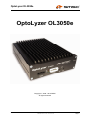
1
Multimedia and Control
Networking Technology
OptoLyzer OL3050e
Version: 1.2.x
User Manual
Document Information:
Version: V1.2.0-3
Date: 2010-10-05
MOST®
Media Oriented Systems Transport
Copyright © 2006 - 2010 SMSC
OptoLyzer OL3050e
Further Information
For more information on SMSC’s automotive products, including integrated circuits, software, and
MOST development tools and modules, visit our web site: http://www.smsc-ais.com. Direct contact
information is available at: http://www.smsc-ais.com/offices.
SMSC Europe GmbH
Bannwaldallee 48
76185 Karlsruhe
GERMANY
SMSC
80 Arkay Drive
Hauppauge, New York 11788
USA
Technical Support
Contact information for technical support is available at: http://www.smsc-ais.com/contact.
Legend
Copyright © 2006 - 2010 SMSC. All rights reserved.
Please make sure that all information within a document marked as ‘Confidential’ or ‘Restricted Access’ is
handled solely in accordance with the agreement pursuant to which it is provided, and is not reproduced or
disclosed to others without the prior written consent of SMSC. The confidential ranking of a document can be
found in the footer of every page. This document supersedes and replaces all information previously supplied.
The technical information in this document loses its validity with the next edition. Although the information is
believed to be accurate, no responsibility is assumed for inaccuracies. Specifications and other documents
mentioned in this document are subject to change without notice. SMSC reserves the right to make changes to
this document and to the products at any time without notice. Neither the provision of this information nor the sale
of the described products conveys any licenses under any patent rights or other intellectual property rights of
SMSC or others. There are a number of patents and patents pending on the MOST technology and other
technologies. No rights under these patents are conveyed without any specific agreement between the users and
the patent owners. The products may contain design defects or errors known as anomalies, including but not
necessarily limited to any which may be identified in this document, which may cause the product to deviate from
published descriptions. Anomalies are described in errata sheets available upon request. SMSC products are not
designed, intended, authorized or warranted for use in any life support or other application where product failure
could cause or contribute to personal injury or severe property damage. Any and all such uses without prior
written approval of an officer of SMSC will be fully at your own risk. MediaLB, SMSC and MOST are registered
trademarks of Standard Microsystems Corporation (“SMSC”) or its subsidiaries. Other names mentioned may be
trademarks of their respective holders.
SMSC disclaims and excludes any and all warranties, including without limitation any and all implied warranties of
merchantability, fitness for a particular purpose, title, and against infringement and the like, and any and all
warranties arising from any course of dealing or usage of trade. In no event shall SMSC be liable for any direct,
incidental, indirect, special, punitive, or consequential damages; or for lost data, profits, savings or revenues of
any kind; regardless of the form of action, whether based on contract; tort; negligence of SMSC or others; strict
liability; breach of warranty; or otherwise; whether or not any remedy of buyer is held to have failed of its essential
purpose, and whether or not SMSC has been advised of the possibility of such damages.
User Manual
Page 2
Copyright © 2006 - 2010 SMSC
Document Version: V1.2.0-3
Date: 2010-10-05
OptoLyzer OL3050e
OptoLyzer OL3050e
Copyright © 2006 - 2010 SMSC
All rights reserved
User Manual
Copyright © 2006 - 2010 SMSC
Document Version: V1.2.0-3
Date: 2010-10-05
Page 3
OptoLyzer OL3050e
Document History
Version
1.2.0-3
Date
2010-10-05
Section
5.1
5.2
1.2.0-2
1.2.0-2d1
2010-03-15
2010-03-12
First Page
3.1.2
5.2
1.2.0-1
2007-03-28
First Page
5.2
5.2
5.2
1.0.X-2
2006-09-13
1.0.X-1
2006-02-10
User Manual
Page 4
General
1
3.1.1
5.2
-
Comment on changes
Weight added.
Table 5-4: Description of Line IN and Line OUT
improved.
Bar code added
Description of power jacks (main) improved.
MOST ePHY connector assignment corrected: Pin 2
and pin 3 turned.
Bar code added
MOST ePHY connector assignment:
Table 5-3: assignment corrected
Technical Data of the Hardware Trigger Interface:
Table 5-5: assignment corrected
Figure 5-1: added; explanation and note added
Input:
Value of the switching threshold corrected
Document converted to SMSC style
Preface adapted
Table 3-1: LED status: more details
Table 5-2: assignment corrected
First version
Copyright © 2006 - 2010 SMSC
Document Version: V1.2.0-3
Date: 2010-10-05
OptoLyzer OL3050e
Table of Contents
1
PREFACE .........................................................................................................................................7
1.1
Intended Use .................................................................................................................................7
1.2
Scope of Delivery...........................................................................................................................7
1.2.1
Software on the CompactFlash ..............................................................................................7
1.2.2
Software on the USB Stick .....................................................................................................7
1.3
Term Definitions.............................................................................................................................8
2
INTRODUCTION...............................................................................................................................9
2.1
Features in Use with OptoLyzer OL3050e ....................................................................................9
2.2
Typical Application...................................................................................................................... 10
2.2.1
Analyzing the MOST Network as Spy ................................................................................. 11
2.2.2
Performing Control Tasks.................................................................................................... 11
3
INSTALLATION ............................................................................................................................. 12
3.1
OptoLyzer OL3050e System Description ................................................................................... 12
3.1.1
Front View of the OptoLyzer OL3050e................................................................................ 12
3.1.2
Rear Panel of OptoLyzer OL3050e ..................................................................................... 14
3.1.3
Connectivity Diagram .......................................................................................................... 16
3.1.3.1
3.1.3.2
3.2
3.3
4
Connectivity Diagram – Front Panel ...............................................................................................16
Connectivity Diagram – Rear Panel................................................................................................17
Software on the OptoLyzer OL3050e ......................................................................................... 18
Laptop/PC and OptoLyzer OL3050e Software Structure ........................................................... 18
MAINTENANCE OF THE OPTOLYZER OL3050E....................................................................... 19
4.1
Service Panel on the Rear Panel ............................................................................................... 19
4.1.1
Rear Panel of OptoLyzer OL3050e: Service....................................................................... 19
4.1.2
Connectivity ......................................................................................................................... 20
4.2
Update CompactFlash................................................................................................................ 21
4.3
Update PCI Board (DOS Tools) ................................................................................................. 22
4.4
Update All (CompactFlash and PCI Board)................................................................................ 23
5
5.1
5.2
TECHNICAL SPECIFICATION...................................................................................................... 24
Mechanical Characteristics......................................................................................................... 24
Electrical Characteristics ............................................................................................................ 25
APPENDIX A: FURTHER READING ................................................................................................... 27
APPENDIX B: LIST OF FIGURES ....................................................................................................... 28
APPENDIX C: LIST OF TABLES ......................................................................................................... 29
APPENDIX D: INDEX ........................................................................................................................... 30
User Manual
Copyright © 2006 - 2010 SMSC
Document Version: V1.2.0-3
Date: 2010-10-05
Page 5
OptoLyzer OL3050e
User Manual
Page 6
Copyright © 2006 - 2010 SMSC
Document Version: V1.2.0-3
Date: 2010-10-05
OptoLyzer OL3050e
1 Preface
1.1 Intended Use
This SMSC product is intended to be used for developing, testing, or analyzing MOST® based
multimedia products and systems by persons with experience in developing multimedia devices.
The operation of this SMSC product is only admitted with original SMSC devices, e.g., provided power
supply.
1.2 Scope of Delivery
The OptoLyzer OL3050e is delivered with:
•
OptoLyzer OL3050e
•
User Manual (printed version)
•
Power-supply
•
Cables
•
Accessories
Please check your shipment for completeness.
Please direct complaints to [email protected] (Europe and Asia)
[email protected] (America). Providing the delivery note number eases the handling.
or
to
1.2.1 Software on the CompactFlash
The CompactFlash™ comes with:
•
Microsoft Windows CE™ as operating system
•
Microsoft Windows CE loader
•
Extended software with spy functionality and MOST drivers, MOST Server
1.2.2 Software on the USB Stick
The USB stick comes with a complete backup of the CompactFlash. In addition, maintenance utilities
are offered on the USB stick (described in section 4.2 on page 21).
User Manual
Copyright © 2006 - 2010 SMSC
Document Version: V1.2.0-3
Date: 2010-10-05
Page 7
OptoLyzer OL3050e
1.3 Term Definitions
For better understanding of the following chapters, this section provides explanation to special terms,
used in the description of the OptoLyzer OL3050e.
Term
Definitions
Client
The connected laptop/PC is called client, additional or target PC. The OptoLyzer
OL3050e is designated as host.
Controlling
software
A software that is running on the client. It manages the communication with the
OptoLyzer OL3050e. The controlling software comprises both the handling of
spied data and performing control tasks.
Event
The OptoLyzer Suite is working with a common format. Therefore the incoming
data is converted to Events.
Host
The OptoLyzer OL3050e is designated as host. The connected laptop/PC is
called client, additional or target PC.
INIC
Intelligent Network Interface Controller
MOST Server
The MOST Server is an application that starts automatically on the OptoLyzer
OL3050e. It manages control and/or analyzing tasks and the communication to
the connected laptop/PC the OptoLyzer Suite is running.
OptoLyzer G2
3050e
This product comprises OptoLyzer Suite and OptoLyzer OL3050e.
OptoLyzer
OL3050e
Hardware of the OptoLyzer G2 3050e. It will be connected into the MOST
Network. Afterwards it takes the data for further processing.
OptoLyzer Suite
This is the software of the OptoLyzer G2 3050e. It covers the OptoLyzer Suite
main window and Viewer, Recorder, Graph and Watch. In addition, the
Transceiver and the MOST Interface Control can be started in the OptoLyzer
Suite.
UTP
Unshielded twisted pair cable
Table 1-1: Term Definitions
User Manual
Page 8
Copyright © 2006 - 2010 SMSC
Document Version: V1.2.0-3
Date: 2010-10-05
OptoLyzer OL3050e
2 Introduction
The OptoLyzer OL3050e is a versatile hardware for debugging and analyzing Control and Packet data
in a MOST50 electrical network. It provides connection to the MOST50 electrical network via a MOST
ePHY connector that is based on the Electrical Physical Layer. When used in combination with the
OptoLyzer Suite all data is transferred via an Ethernet connection to a PC running the OptoLyzer
Suite. The device is prepared to work in laboratory (stationary) environments (voltage range of 100 –
240 V DC transformed to 12 V). The OptoLyzer OL3050e is able to run in timing master, slave, and
bypass mode.
2.1 Features in Use with OptoLyzer OL3050e
These are the features of the OptoLyzer OL3050e:
•
Versatile MOST Network analysis tool for Control and Packet data
•
MOST50 network electrical interface
•
Ethernet interface allows remote control and analysis data on PC
•
Line IN/OUT interface
•
S/PDIF IN/OUT interface
•
4 opto-coupled TTL hardware trigger
•
LEDs indicating different states of device and network
•
Support for 48kHz system sample rates
•
Time stamp resolution: 1 µs; accuracy: 1 frame
•
MOST50 UTP cable set
•
Bootable USB stick for firmware update and service purposes
•
Optional connections for keyboard, mouse and monitor, USB
User Manual
Copyright © 2006 - 2010 SMSC
Document Version: V1.2.0-3
Date: 2010-10-05
Page 9
OptoLyzer OL3050e
2.2 Typical Application
A MOST Network might consist of various MOST devices. State-of-the-art multimedia systems need
powerful tools for both finding of irregularities and controlling of the MOST Network’s interfaces. The
OptoLyzer OL3050e is developed to perform these tasks.
A typical application is depicted in Figure 2-1 below. The OptoLyzer OL3050e is part of the MOST
Network and spies its data. The data is transmitted to a connected PC via an Ethernet connection. A
controlling software (e.g., OptoLyzer Suite) handles the spied data. Additionally, control tasks can be
performed via a controlling software.
Figure 2-1: Typical Application of the OptoLyzer OL3050e
The following sections describe the concepts for both:
•
Analyzing the MOST Network as spy
And
•
Performing control tasks (via e.g., OptoLyzer Suite)
User Manual
Page 10
Copyright © 2006 - 2010 SMSC
Document Version: V1.2.0-3
Date: 2010-10-05
OptoLyzer OL3050e
2.2.1 Analyzing the MOST Network as Spy
Since the OptoLyzer OL3050e spies data on the MOST Network by default it has simply to be
connected in a MOST Network to use this feature. In this mode it is able to deal with heavy data loads.
Data recovery is ensured. When operating as spy the OptoLyzer OL3050e is invisible in the MOST
Network. The OptoLyzer OL3050e spies the complete traffic on the Control data channel and the
Packet data channel of a MOST Network. An included application – the MOST Server - takes the
incoming data and converts it into a common format named ‘Events’. The MOST Server provides a
socket connection for further processing. If the OptoLyzer OL3050e is used in combination with
controlling software the spied data can be displayed in different kind. E.g., the data can be monitored
in a window for on-line analyzing. Furthermore the data can be shown in a graph for statistic purposes.
Even data recording is possible for off-line analyzing later on (see Figure 2-1). Trigger inputs allow
interfacing with external hardware events.
2.2.2 Performing Control Tasks
The OptoLyzer OL3050e can also operate as timing master or slave. Then the OptoLyzer OL3050e
supports performing control tasks via controlling software on a client. For example the mode of the
OptoLyzer OL3050e can be changed. Normal operation assumed, messages can be sent and viewed
for e.g., test or simulation on the MOST Network. In addition, the OptoLyzer OL3050e is able to route
streaming data.
User Manual
Copyright © 2006 - 2010 SMSC
Document Version: V1.2.0-3
Date: 2010-10-05
Page 11
OptoLyzer OL3050e
3 Installation
This chapter describes the elements and connectors of the OptoLyzer OL3050e. A connectivity
diagram shows how to connect the OptoLyzer OL3050e and the client in a typical MOST Network
application.
Specific aspects of the software structure (OptoLyzer OL3050e software and controlling software on
the client) are shown in section 3.2 and 3.3.
3.1 OptoLyzer OL3050e System Description
The OptoLyzer OL3050e comes with all components configured and prepared for default operation.
When used in combination with the OptoLyzer Suite it needs to be connected to a PC running the
OptoLyzer Suite. The following sections describe the different views of the OptoLyzer OL3050e.
Service aspects as e.g., an update procedure are handled in chapter 4 on page 19.
3.1.1 Front View of the OptoLyzer OL3050e
The front view of the OptoLyzer OL3050e provides access to external interfaces and elements for
controlling and information.
Figure 3-1: OptoLyzer OL3050e (Front View)
The components are described from left to right:
Trigger interface:
There are four trigger inputs that can be used if needed. In the spy operation mode the software will
detect input trigger changes and send them over the Ethernet. For further technical details refer to
chapter 5.2 on page 25.
User Manual
Page 12
Copyright © 2006 - 2010 SMSC
Document Version: V1.2.0-3
Date: 2010-10-05
OptoLyzer OL3050e
LEDs:
To the right of the trigger interface there are three LEDs among each other. Each of them is
supporting different functionalities depending on the operating mode.
LED label
R (Ready)
Color
Red
M (Message)
Yellow
L (Lock)
Green
Description
The red LED indicates different start up states of the OptoLyzer
OL3050e. If it is continuously lighting the OptoLyzer OL3025o is
ready.
This LED is blinking if a twinkle command is sent from e.g.,
OptoLyzer Suite (twinkle LED).
This LED is on if:
• the MOST Network is locked and
•
the OptoLyzer OL3050e is in node mode (master or slave) and
•
a Control or Packet message is addressed to the OptoLyzer
OL3050e node.
This LED is on when the MOST Network is locked.
Table 3-1: Status LEDs
MOST50 ePHY connector:
The OptoLyzer OL3050e can be connected to the MOST Network via a MOST ePHY connector (AMP
1376366-1):
•
ETxp, ETxn:
Electrical positive and negative output for MOST Network
•
ERxp, ERxn:
Electrical positive and negative input for MOST Network
For more details regarding the pin assignment refer to section 5.2 on page 25.
Audio Line IN/OUT:
The OptoLyzer OL3050e provides one audio input and one audio output connector centered on its
front panel. For technical details refer to section 5.2 on page 25.
LED Power:
This green colored LED indicates that power is switched on.
User Manual
Copyright © 2006 - 2010 SMSC
Document Version: V1.2.0-3
Date: 2010-10-05
Page 13
OptoLyzer OL3050e
3.1.2 Rear Panel of OptoLyzer OL3050e
The rear panel of the OptoLyzer OL3050e provides access to power jack, power switch, a reset
button, interfaces to a remote PC and to audio devices. In addition, several service interfaces are
supported but hidden behind a service panel. This panel must be unscrewed in a service case to get
access to the hidden service interfaces. The normal operation mode is depicted below. The service
mode is described in chapter 4 on page 19.
1
Power
Ethernet
Reset
I
0
3 2
S/PDIF
OUT
S/PDIF
IN
Figure 3-2: OptoLyzer OL3050e (Rear Panel: Normal Operation)
All components of the rear panel are described from left to right and top down:
Power jack (mains):
The power jack needs a power supply in a voltage range of 8 V – 30 V DC. The OptoLyzer OL3050e
comes with an AC power supply unit (voltage range from 100 V to 240 V DC). For technical details
refer to section 5.2 on page 25.
Power on/off switch:
The power on/off switch is located to the right of the power jack. In position ‘I’ the OptoLyzer OL3050e
is on, in position ‘0’ the power is switched off.
The OptoLyzer OL3050e supports ignition. If pin 2 (ION) is connected with GND the OptoLyzer
OL3050e is switched off. If pin 2 (ION) is not connected or is connected with a high level signal (8 V –
30 V) the OptoLyzer OL3050e is switched on. For technical details refer to section 5.2 on page 25.
Reset:
If this button is pressed the OptoLyzer OL3050e is restarted.
Ethernet Interface:
This interface is the standard communication port that connects the OptoLyzer OL3050e to a PC via a
100Base-T Ethernet connection. Controlling software running on this PC e.g., the OptoLyzer Suite is
able to control the OptoLyzer OL3050e and to receive its data. The connector is a standard RJ45. Left
hand two LEDs give information on connection (Link LED: yellow) and traffic (Activity LED: green).
User Manual
Page 14
Copyright © 2006 - 2010 SMSC
Document Version: V1.2.0-3
Date: 2010-10-05
OptoLyzer OL3050e
S/PDIF
For monitoring and audio test, the OptoLyzer OL3050e supports one digital S/PDIF IN and OUT
connection.
Regarding the S/PDIF IN: The S/PDIF controller contains a sample rate converter. This means that the
S/PDIF IN data is not exactly the data coming into the MOST bus.
User Manual
Copyright © 2006 - 2010 SMSC
Document Version: V1.2.0-3
Date: 2010-10-05
Page 15
OptoLyzer OL3050e
3.1.3 Connectivity Diagram
The following sections describe how the OptoLyzer OL3050e can be integrated in a MOST50 network.
In addition the connections are shown that are mandatory like the 100Base-T Ethernet connection with
the laptop/PC running controlling software and the power supply. Furthermore some connections are
menitioned that can be used for optional functionality like monitor, mouse, keyboard, analog, and
digital audio devices.
3.1.3.1 Connectivity Diagram – Front Panel
Figure 3-3 depicts the connectivity diagram of the front panel. It shows how the OptoLyzer OL3050e
can be integrated in a MOST50 network.
Figure 3-3: Connectivity Diagram – Front Panel
User Manual
Page 16
Copyright © 2006 - 2010 SMSC
Document Version: V1.2.0-3
Date: 2010-10-05
OptoLyzer OL3050e
3.1.3.2 Connectivity Diagram – Rear Panel
The connectivity diagram of the rear panel is depicted in Figure 3-4.
Power Supply
Reset
I
0
Power
S/PDIF S/PDIF
OUT
IN
For connection
concept see
OptoLyzer G2 30xx
Start-up Guide
Audio device
with S/PDIF
PC with OptoLyzer
Suite (e.g.)
Figure 3-4: Connectivity Diagram – Rear Panel (Normal Operation)
User Manual
Copyright © 2006 - 2010 SMSC
Document Version: V1.2.0-3
Date: 2010-10-05
Page 17
OptoLyzer OL3050e
3.2 Software on the OptoLyzer OL3050e
The OptoLyzer OL3050e is delivered ready for use. All software components are provided as a
firmware image on a 64 MB CompactFlash. This image is based on the operating system Microsoft
Windows CE™ extended by modules needed for MOST, communication interfaces and the server
application. A bootable USB stick comprises a backup image of the CompactFlash.
Note:
If both, the USB stick and the CompactFlash are inserted at the same time, the OptoLyzer
OL3050e will use the USB stick during the startup procedure by default.
3.3 Laptop/PC and OptoLyzer OL3050e Software Structure
When the OptoLyzer OL3050e is switched a specific application – the MOST Server – starts up
automatically. It manages control and/or analyzing tasks and the communication to a connected
laptop/PC controlling software is running on.
OptoLyzer OL3050e
Laptop/PC
100 Base-T
Ethernet
connection
Controlling
Software
MOST Server
MOST ePHY
connector
4 Trigger
inputs
4
MOST
Network
Device
under Test
Figure 3-5: Software Structure
The interaction of the two software parts is managed via a 100 Base-T Ethernet connection. It is
shown in Figure 3-5 above. The OptoLyzer OL3050e provides two logical channels for
communication: a spy and a control channel. The channel, which handles controlling tasks, operates
bidirectional, the channel, which transfers spy data, operates unidirectional namely in direction
OptoLyzer OL3050e to the connected laptop/PC. For further information refer to
OptoLyzer Socket Protocol [1]
User Manual
Page 18
Copyright © 2006 - 2010 SMSC
Document Version: V1.2.0-3
Date: 2010-10-05
OptoLyzer OL3050e
4 Maintenance of the OptoLyzer OL3050e
This chapter describes how to get access to the service panel and its interfaces. Section 4.2 covers
the update of the CompactFlash. OptoLyzer OL3050e test and upgrade tools of the PCI Board are
described in section 4.3.
4.1 Service Panel on the Rear Panel
In service cases e.g., when updating the system, the service panel must be unscrewed at the rear
panel. Several service interfaces are supported but hidden behind this service panel. The service
mode is depicted below. The normal operation mode and the associated interfaces are described in
section 3.1.2 on page 14.
4.1.1 Rear Panel of OptoLyzer OL3050e: Service
USB 1
Reset
I
0
Power
USB 2
Compact
Flash
Ethernet
Keyboard
Mouse
S/PDIF
OUT
S/PDIF
IN
VGA
Figure 4-1: OptoLyzer OL3050e (Rear Panel: Service Operation)
Only the additional service interfaces are described below:
USB interfaces (2x):
Additional devices can be connected via two USB 2.0 connectors. E.g., the system can be updated via
an attached USB stick.
PS2 interface:
The OptoLyzer OL3050e can be used without any external interfaces, but there is a PS2 interface for
mouse and keyboard. It can be useful to connect a mouse and a keyboard for more functionality. The
mouse and the keyboard are not part of the shipping.
Note:
Y cable for mouse and keyboard is needed.
User Manual
Copyright © 2006 - 2010 SMSC
Document Version: V1.2.0-3
Date: 2010-10-05
Page 19
OptoLyzer OL3050e
CompactFlash slot:
A CompactFlash slot is placed in the center of the rear panel. The delivered CompactFlash provides
the operating system Microsoft Windows CE™ and all other software that is necessary for analyzing
and controlling purposes.
VGA interface:
The hardware of the OptoLyzer OL3050e supports a VGA interface for connecting a VGA monitor.
The display will be recognized automatically. The enclosed adapter can be used for connecting a VGA
monitor.
4.1.2 Connectivity
The connectivity diagram of the rear panel is depicted in Figure 4-2.
Update via
USB stick
USB 2
I
0
Power
USB 1
Reset
Compact
Flash
VGA
Ethernet
S/PDIF
OUT
S/PDIF
IN
Y cable
PS/2
Keyboard
optional
Mouse
optional
Monitor
optional
Figure 4-2: Connectivity Diagram – Rear Panel (Service Operation)
User Manual
Page 20
Copyright © 2006 - 2010 SMSC
Document Version: V1.2.0-3
Date: 2010-10-05
OptoLyzer OL3050e
4.2 Update CompactFlash
The OptoLyzer OL3050e is shipped with a bootable USB stick. This USB stick contains a complete
backup of the original CompactFlash data (factory default). The CompactFlash can be recovered
using the backup of the USB stick. The procedure how to recover the CompactFlash is described
below.
To recover or update the OptoLyzer OL3050e obey the following procedure:
1. Switch off the OptoLyzer OL3050e.
2. Disconnect the connectors on the rear panel.
3. Unscrew the service panel.
4. Reconnect the power supply.
5. Connect a mouse, a keyboard and a monitor (not part of the shipment) according Figure 4-2.
6. Plug in the delivered bootable USB stick into a USB slot.
7. Restart the OptoLyzer OL3050e.
8. The OptoLyzer OL3050e displays a boot menu.
Note:
If no item is selected for some time the CompactFlash and the firmware are updated
automatically (described in section 4.4 on page 23).
9. Enter ‘1’ for ‘Update CompactFlash’.
10. Follow the instructions. The CompactFlash memory will be overwritten.
11. After finishing the recovery procedure switch off the OptoLyzer OL3050e.
12. Remove the USB stick.
13. Disconnect the connectors on the rear panel.
14. Screw on the service panel.
15. Connect the power supply.
16. Restart the OptoLyzer OL3050e.
17. After the LED ‘R’ stops twinkling, switch off the OptoLyzer OL3050e.
18. Reconnect all cables.
19. Start the OptoLyzer OL3050e again.
User Manual
Copyright © 2006 - 2010 SMSC
Document Version: V1.2.0-3
Date: 2010-10-05
Page 21
OptoLyzer OL3050e
4.3 Update PCI Board (DOS Tools)
This USB stick also contains the DOS tools. Within the DOS tools the following options are provided:
•
Check or Write License Keys
•
Update FPGA firmware (e.g., OP2400)
•
Update MOST Controller (INIC) firmware
Both FPGA firmware and MOST Controller firmware update can be performed automatically (easy) or
manually (advanced).
The procedure to use the DOS tools is described below:
1. Switch off the OptoLyzer OL3050e.
2. Disconnect the connectors on the rear panel.
3. Unscrew the service panel.
4. Connect the power supply.
5. Connect a mouse, a keyboard and a monitor (not part of the shipment) according Figure 4-2.
6. Switch on the power.
7. The OptoLyzer OL3050e displays a boot menu.
Note:
If no item is selected for some time the CompactFlash and the PCI Board are updated
automatically (described in section 4.4 on page 23).
8. Enter ‘2’ for Update PCI Board (DOS Tools).
9. Follow the instructions when working with the DOS tools.
For details how to use the DOS tools options please refer to the additional user manual DOS Tools
MOST PC Interfaces that can be found on the CD.
User Manual
Page 22
Copyright © 2006 - 2010 SMSC
Document Version: V1.2.0-3
Date: 2010-10-05
OptoLyzer OL3050e
4.4 Update All (CompactFlash and PCI Board)
The USB stick offers the possibility to automatically update the CompactFlash and the PCI Board
(FPGA firmware and MOST Controller firmware) in one step. This option is preset as default in the
boot menu of the USB stick.
It is assumed the OptoLyzer OL3050e is connected according Figure 3-3 and Figure 3-4. The
procedure to use the DOS tools is described below:
1. Switch off the OptoLyzer OL3050e.
2. Disconnect the connectors on the rear panel.
3. Unscrew the service panel.
4. Connect the power supply.
5. Connect a mouse, a keyboard and a monitor (not part of the shipment) according Figure 4-2.
6. Switch on the power.
7. The OptoLyzer OL3050e displays a boot menu.
8. Enter ‘3’ for ‘Update All (CompactFlash and PCI Board)’. Alternatively wait for some time. Then
this item is performed automatically.
9. Follow the instructions.
10. After finishing the update switch off the OptoLyzer OL3050e.
11. Remove the USB stick.
12. Disconnect the connectors on the rear panel.
13. Screw on the service panel.
14. Reconnect all cables.
15. Start the OptoLyzer OL3050e again.
User Manual
Copyright © 2006 - 2010 SMSC
Document Version: V1.2.0-3
Date: 2010-10-05
Page 23
OptoLyzer OL3050e
5 Technical Specification
5.1 Mechanical Characteristics
Mechanical Dimensions
Mechanical dimensions of the OptoLyzer OL3050e in millimeters, without screws, plugs and switches:
Height
43.5
Width
134
Depth
175
Table 5-1: Mechanical Dimensions of the OptoLyzer OL3050e
Weight of the OptoLyzer OL3050e: 1134 g.
Environmental Specification
Protection against Over Temperature
The computer system integrates temperature sensitive components. Therefore do not cover the
device with paper, textiles or other objects. Covering disables the passive cooling (cooling rips). Make
sure to allow enough airflow to the computer system, when the device is assembled. Do never place
the running computer system in a closed case or box. Clean the surface of the computer system from
dust, oil and other isolating materials, to prevent a reduction of the cooling efficiency.
Operating mode:
Parameter
Ambient temperature
Relative humidity (non-condensing)
Values
0° to 50°C
80%
Non-operating mode (Storage):
Parameter
Ambient temperature
Relative humidity (non-condensing)
User Manual
Page 24
Values
-40° to 85°C
95%
Copyright © 2006 - 2010 SMSC
Document Version: V1.2.0-3
Date: 2010-10-05
OptoLyzer OL3050e
5.2 Electrical Characteristics
Power Supply
Operating Voltage:
Power Consumption: Operation (typical):
8 V-30 V (DC)
14 W
Power Input / Main Supply Connector
Pin
1
2
3
Description
Power
ION
GND
Table 5-2: Power Supply Connector
MOST ePHY connector assignment:
The pin assignment of the MOST ePHY connector depicted in section 3.1.1 is described in Table 5-3.
Pin
2
3
6
7
1, 4, 5, 8
Name
ETXP
ETXN
ERXN
ERXP
EGND
Description
Transmitter positive
Transmitter negative
Receiver negative
Receiver positive
ePHY Ground
Table 5-3: Electrical Interface – MOST ePHY Connector
Audio Line IN/OUT
The electrical properties are described in Table 5-4.
Name
Line OUT
Line IN
Description
Audio stereo signal output:
VOutTyp = 0.9 V (RMS) at RL = 5 kΩ,
RLMin= 3 kΩ
3.5 mm plug
Audio stereo signal input:
VInMax = 1.1 V (RMS) at RIn = 12 kΩ
3.5 mm plug
Table 5-4: Line IN/OUT
User Manual
Copyright © 2006 - 2010 SMSC
Document Version: V1.2.0-3
Date: 2010-10-05
Page 25
OptoLyzer OL3050e
Technical Data of the Hardware Trigger interface
Hardware
Trigger
Pin
Signal
1
1
GND
2
2
Input
3
GND
3
4
Input
5
GND
4
6
Input
7
GND
Power
8
Input
9
GND
10
Do not
connect
(future
use)
Table 5-5: Connector Pin List of the Hardware Trigger Interface
Table 5-5 describes the pin connection of the hardware trigger interface.
Figure 5-1: Pin Equivalent for Hardware Trigger Input Pins
Figure 5-1 shows that there is an internal pull-up to 5 V. The input is not compatible to TTL logic.
Note:
An external circuit must match the Pin Equivalent for Hardware Trigger Input Pins depicted in
Figure 5-1.
•
Input:
Switching threshold = 4.5 V
UIN max = 16 V
User Manual
Page 26
Copyright © 2006 - 2010 SMSC
Document Version: V1.2.0-3
Date: 2010-10-05
OptoLyzer OL3050e
Appendix A: Further Reading
1.
2.
3.
4.
5.
OptoLyzer Socket Protocol *
OptoLyzer Suite User Manual **
OptoLyzer G2 30xx Start-up Guide **
Syntax Compiler BNBuild User Manual **
DOS Tools MOST PC Interfaces *
* Contact [email protected].
** The current version of the documents can be downloaded from http://www.smsc-ais.com.
User Manual
Copyright © 2006 - 2010 SMSC
Document Version: V1.2.0-3
Date: 2010-10-05
Page 27
OptoLyzer OL3050e
Appendix B: List of Figures
Figure 2-1: Typical Application of the OptoLyzer OL3050e .................................................................. 10
Figure 3-1: OptoLyzer OL3050e (Front View) ....................................................................................... 12
Figure 3-2: OptoLyzer OL3050e (Rear Panel: Normal Operation)........................................................ 14
Figure 3-3: Connectivity Diagram – Front Panel ................................................................................... 16
Figure 3-4: Connectivity Diagram – Rear Panel (Normal Operation).................................................... 17
Figure 3-5: Software Structure .............................................................................................................. 18
Figure 4-1: OptoLyzer OL3050e (Rear Panel: Service Operation) ....................................................... 19
Figure 4-2: Connectivity Diagram – Rear Panel (Service Operation) ................................................... 20
Figure 5-1: Pin Equivalent for Hardware Trigger Input Pins.................................................................. 26
User Manual
Page 28
Copyright © 2006 - 2010 SMSC
Document Version: V1.2.0-3
Date: 2010-10-05
OptoLyzer OL3050e
Appendix C: List of Tables
Table 1-1: Term Definitions ..................................................................................................................... 8
Table 3-1: Status LEDs ......................................................................................................................... 13
Table 5-1: Mechanical Dimensions of the OptoLyzer OL3050e............................................................ 24
Table 5-2: Power Supply Connector ..................................................................................................... 25
Table 5-3: Electrical Interface – MOST ePHY Connector ..................................................................... 25
Table 5-4: Line IN/OUT ......................................................................................................................... 25
Table 5-5: Connector Pin List of the Hardware Trigger Interface.......................................................... 26
User Manual
Copyright © 2006 - 2010 SMSC
Document Version: V1.2.0-3
Date: 2010-10-05
Page 29
OptoLyzer OL3050e
Appendix D: INDEX
A
AMP 1376366-1
Audio Line IN/OUT
13
13
C
Client
CompactFlash
CompactFlash Slot
Connectivity Diagram
Connectivity Diagram Front
Connectivity Diagram Rear
Control Tasks
Controlling software
8
18
20
16
16
17
11
8
D
Data Recovery
Definition of Terms
11
8
E
Electrical Characteristics
Environmental Specification
Ethernet Interface
Event
Events
25
24
14
8
11
F
Features
Front View
9
12
H
Hardware Trigger pins
Host
26
8
I
Information about LEDs
Installation
13
12
L
LED Power
LED Status
LEDs
Line IN
Line OUT
Lock LED
13
13
13
25
25
13
User Manual
Page 30
M
Mechanical Dimensions
Message
MOST ePHY Connector Assignment
MOST Server
MOST50 ePHY Connector
O
OL3050e Software
OptoLyzer OL3050e Software
Over Temperature
18
18
24
P
Packing List
Pin Assignment
Power Input
Power Jack
Power Supply
Power Switch Button
7
25
25
14
25
14
R
Ready
Rear Panel
13
14
S
S/PDIF
Scope of Delivery
Service Mode
Service Panel
Spy Tasks
System Description
15
7
14
14
11
12
T
Technical Data of the Hardware Trigger
Interface
Technical Specification
Term Definitions
Trigger Interface
Typical Application
26
24
8
12
10
U
UTP
Copyright © 2006 - 2010 SMSC
Document Version: V1.2.0-3
24
13
25
8, 18
13
Date: 2010-10-05
8
OptoLyzer OL3050e
Note:
User Manual
Copyright © 2006 - 2010 SMSC
Document Version: V1.2.0-3
Date: 2010-10-05
Page 31
OptoLyzer OL3050e
User Manual
Page 32
Copyright © 2006 - 2010 SMSC
Document Version: V1.2.0-3
Date: 2010-10-05