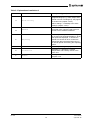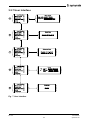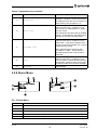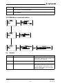
1
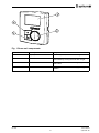
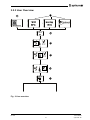
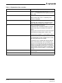
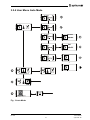
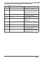
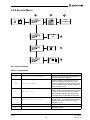
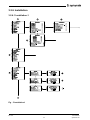
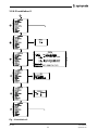
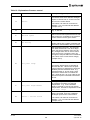
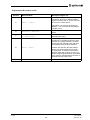
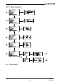
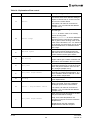
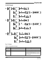
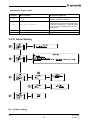
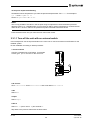
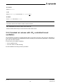
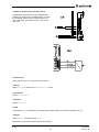
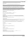
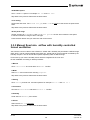
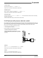
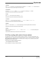
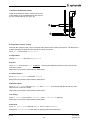
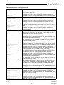
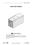
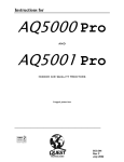
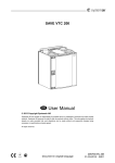
EC Vent
User Manual
-EN_GB
2012-11-21 A004
Contents
1 Warnings................................................................................................................................... 1
2 Product Description.................................................................................................................... 1
2.1 Room unit ........................................................................................................................ 1
2.1.1 Display Symbols ..................................................................................................... 3
3 Operation .................................................................................................................................. 4
3.1 Before starting.................................................................................................................. 4
3.2 Program overview ............................................................................................................ 4
3.2.1 Navigation .............................................................................................................. 4
3.2.2 User menu.............................................................................................................. 4
3.2.3 User Overview ........................................................................................................ 6
3.2.4 User Menu Auto Mode ............................................................................................ 8
3.2.5 Service Menu .........................................................................................................10
3.2.6 Installation .............................................................................................................11
3.2.7 User Interface .........................................................................................................15
3.2.8 Alarm Menu ............................................................................................................16
3.2.9 Modbus communication...........................................................................................17
3.2.10 Temperature Control..............................................................................................18
3.2.11 CO2 Control ..........................................................................................................20
3.2.12 Humidity Control ...................................................................................................22
3.2.13 Manual Control .....................................................................................................24
3.2.14 Time Control .........................................................................................................26
3.2.15 Pressure Control ...................................................................................................27
3.2.16 DI Control .............................................................................................................29
3.2.17 Flow Control .........................................................................................................31
3.2.18 Slave Control ........................................................................................................33
3.2.19 Heater/Cooler Control............................................................................................34
3.2.20 Output ..................................................................................................................38
3.2.21 Alarm Setting ........................................................................................................39
3.3 Set up cases ....................................................................................................................40
3.3.1 Pressure control with outdoor temperature compensation ..........................................40
3.3.2 Constant air volume with CO2 controlled forced ventilation.........................................43
3.3.3 Manual fixed min. airflow with humidity controlled forced ventilation ...........................46
3.3.4 Fixed rpm with presence detector control..................................................................47
3.3.5 Free cooling with control of room radiator .................................................................48
3.4 Set up of operation schedules ...........................................................................................50
3.4.1 Set up example.......................................................................................................52
1 Warnings
The following admonitions will be presented in the different sections of the document.
Danger
• Make sure that the Mains supply to the unit is disconnected before performing any maintenance or
electrical work!
• All electrical connections must be carried out by an authorized installer and in accordance with
local rules and regulations.
2 Product Description
2.1 Room unit
The objective of the room unit is to display the information provided by the installed sensors and make
it possible for the user to enter desired settings. The room unit is equipped with 2 internal sensors;
Temperature and humidity sensor, which register the temperature and humidity in the location of the
installed room unit. It is possible to connect 2 extra sensors to the internal connection block.
Up to 10 room units can be active simultaneously.
Note:
The installed room units can only be regulated one by one. It is not possible to perform settings on
two or more controls simultaneously!
In order for the room unit to function the control board needs to be installed and connected. See
“Installation Instructions” for more information.
EC Vent
User Manual
1
Systemair AB
Fig. 1 Room unit components
Position
Description
Explanation
1
Display
Shows symbols, menus and settings
2
Selection knob
Move through the menu lists or change settings
and values by turning the knob left or right
3
Confirm button
Confirm menu choices or settings by pressing
the button
4
Back button
Step back in the menu levels by pressing the
button
EC Vent
User Manual
2
Systemair AB
2.1.1 Display Symbols
Symbol
Description
Explanation
Fan speed
Illustrates the current set fan speed. The speed
setting is stepless or in steps determined by
the user. The speed is also displayed as
percentage of the maximum fan speed at the
bottom of the display (valid if manual mode is
selected)
Empty symbol equals stopped fan and
completely filled symbol equals maximum
speed (100%)
The fan speed can be set manually by turning
the selection knob while in manual mode.
Temp set
Illustrates the current set temperature.
Temperature icon is connected to the set
point for the heater/cooler. If no heater/cooler
controller is activated the icon indicates the
setting of the first temperature controller for
the fan. If there are no temperature controllers
in the system the temperature icon is not
shown. The temperature is set in steps of 0,5°C
and can be changed manually by turning the
selection knob.
Service
Access to the service/setup menu by pressing
the confirmation button
Login to “Service” with “1111” and to “Setup”
with “2222”.
Alarm
Shows only if an alarm is active and not
blocked. Icon is flashing when an alarm is
active
Check box
Used to marked selectable and selected items
(unmarked and marked boxes).
EC Vent
User Manual
3
Systemair AB
3 Operation
3.1 Before starting
Before starting up the system make sure you have checked the following:
• That the equipment is installed according to the installation instructions
• That the correct accessories are used for the intended function
• That you have read and understood this manual.
3.2 Program overview
The program interface is separated in three levels.
• User level is intended to be used by any user of the system. It’s only possible to change a limited
number of parameters
• Service level is intended to be used by persons with some knowledge of the system. For example care
taker or similar
• Installation level is used for advanced setting and is intended for the installation personnel that do the
initial setup of the complete system.
3.2.1 Navigation
The room unit has two buttons and a knob.
• Menu selector (choose function and move in menus)
• Confirm (button to confirm choice)
• Back (button to go back in menu level)
Items in the menu that lead to a sub menu level are marked with >>. Items that lead to a menu with
changeable items are marked with>. Changeable Parameters and values in menus are marked with
underscore. When turning the knob the selected value is marked with inverted background colour. The
Confirm button will enable changes of value, this is indicated by flashing the inverted background colour
on and off.
After a value has been changed the change must be confirmed with the Confirm button. If the back button
is used the value will go back to previous. Inactivity for 1 min. is the same as selecting back button.
The display back light will be activated from any user input. The back light goes off after 1 min. of inactivity
except for the adjusting menu where the back light is always on
The password menu has a time out of 15 sec.
3.2.2 User menu
The control mode list shows activated selection. If only manual is chosen and a manual controller is
selected the controller mode menu is not shown
Manual controller setting menu has no time out.
The temperature icon is connected to the set point for the heater/cooler. If no heater/cooler controller is
activated the icon is connected to the first temperature controller for the fan. If there are no temperature
controllers in the system the temperature icon is not shown. The Alarm icon flashes in case of alarm and
an alarm message is shown; if more than one alarm is activated the messages alternate.
In the bottom of the display the actual operate mode is shown.
This can be:
• Auto
• Boost: 00:30 (remaining time counter, in this example the remaining boost time is 30 minutes)
EC Vent
User Manual
4
Systemair AB
• Extended time: 00:30 (remaining time counter, in this example the remaining extended time is 30
minutes)
• Away
• Manual: (If the controller is set to stepless the fan signal output is shown in %. If step controller is
selected the selected step is shown.) The manual speed is shown if a manual controller is activated and
the system is in auto mode.
3.2.2.1 Sleep Mode
If the sleep mode is activated the system will go to sleep mode 5 min. after last user interaction, except
when the adjusting menu is selected. When the system is in sleep mode any user input will change the
system to user menu. If a user password is selected a password question will appear.
3.2.2.2 Operation mode
Boost: When entering the Boost function a default time is shown and a time field is selected for edit.
(Boost speed is equal to 100% fan speed)
Default time is set in User interface menu
1. Select a time with the selection knob, confirm the time and the timer starts
2. Return to main menu with the back button or time out
3. Text Boost and remaining time is shown under the display icons
Extended time: Disables the effect of the schedule. If no schedule is programmed the function is
hidden. Same function and procedure as Boost function.
Away: Activates the away speed. Is Aborted by selection of boost, extended time or auto mode. Away
speed is set in User interface menu.
Auto: Return to Auto mode.
Manual: Activate fixed speed with manual setting. Can be step or stepless. The menu for changing speed
has no time out. The fan speed can be higher than the set manual speed if a separate room unit (up to 10
pcs of RU can be installed) gives a higher signal to the fan.
EC Vent
User Manual
5
Systemair AB
3.2.3 User Overview
B
A
Fan S peed <500RP M
12:00
20°C
Monday
12:00
P as s word
C
xxxx
D
Auto
E
Auto
F
Auto
P as s word
S ervice
S etup
xxxx
G
Fig. 2 User overview
EC Vent
User Manual
6
Systemair AB
Table 1: Explanations User overview
Position
Description (figure 2)
A
Shows a warning symbol with the text Fan speed
<500 rpm. Indicates that no fan speed setting has
been made
B
Sleep mode display option.
Will be shown after 5 min. of inactivity if the
function is activated.
User password
C
Displayed after pressing the confirmation button
when standing in sleep mode (chapter 3.2.6.1)
D
Symbol has different meaning:
If manual mode is activated (chapter 3.2.13) the
symbol will change according to the actual fan
speed
If Away, Auto or Boost mode is chosen the symbol
will be filled accordingly (little, medium, full).
For more info. (chapter 2.1.1 and chapter 3.2.4).
E
Symbol has different meaning:
If no temperature control or heater/cooler is used
then the symbol will not be visible
If a heater/cooler is installed the desired working
point of the heater/cooler can be changed here.
If the fan is controlled with the help of a temperature
sensor you can change the desired temperature
between the Max/Min set point here. If a fixed set
point has been chosen the symbol is visible but no
changes can be done (chapter 2.1.1 and chapter
3.2.10).
F
Push to enter either the installation mode or the
service mode
G
Write the password for the mode you want to enter
EC Vent
User Manual
7
Systemair AB
3.2.4 User Menu Auto Mode
þ
Away
Auto
¨
Extended time ¨
Boos t
¨
Manual
¨
Away
¨
Au to
þ
Extended time ¨
Boos t
¨
Manual
¨
Auto
Away
Auto
Exten d ed tim e
Boos t
Manual
¨
¨
þ
¨
¨
A
B
Extended time .
Duration 00 :30
F
Boos t
Away
¨
Auto
¨
Extended time ¨
Boos t
þ
Manual
¨
Away
¨
Auto
¨
Extended time ¨
Boos t
¨
Man u al
þ
Duration 00 :30
G
H
Fan s peed 33%
or
I
Fan s tep 1
C
S et temp /Fixed temp s et
D
S etting
P as s word
S ervice
xxxx
E
Fan S peed <500 R P M
Fig. 3 Auto Mode
EC Vent
User Manual
8
Systemair AB
Table 2: Explanations User menu Auto mode
Position
A
Menu Headline
Description (figure 3)
Away
Activate the Away function. For more info.
(chapter 3.2.2.2 and chapter 3.2.7).
Abort away, boost or extended time.
The fan will then be controlled by the
installed sensors and/or week schedule.
For more info. (chapter 3.2.2.2 and chapter
3.2.6.1).
B
Auto
C
Set temp/Fixed temp set
Change set point of heater/cooler controller
or temperature controlled fan.
D
Setting
Push to enter either the installation mode
or the service mode
Alarm
E
Alarm
F
Extended time
Activate the Extended time function.
For more info. (chapter 3.2.2.2 and chapter
3.2.7).
G
Boost
Activate the Boost function. For more
info. (chapter 3.2.2.2 and chapter 3.2.7)
H
Manual
If manual mode is chosen the fan can be
controlled in a stepless mode if this mode
is chosen (chapter 3.2.13).
I
Fan step 1
If manual mode is chosen the fan can be
controlled in a step mode if this mode is
chosen (chapter 3.2.13).
Symbol appears if there is an active alarm
(chapter 3.2.8).
EC Vent
User Manual
9
Systemair AB
3.2.5 Service Menu
A
B
C
Fan s et point
C ontroller
C o n tro ller n am e
C ontroller name
C ontroller name
C ontroller name
C ontroller name
•
•
•
•
S ervice
Fan s et p o in t ad ju s tm en t
Heater / C ooler s et point
Time and Date
S W Version
•
•
•
•
S ervice
Fan s et point adjus tment
Heater / C o o ler s et p o in t
Time and Date
S W Version
•
•
•
•
S ervice
Fan s et point adjus tment
Heater /C ooler s et point
Tim e an d Date
S W Version
Time and date
HH:MM
DDD
•
•
•
•
S ervice
Fan s et point adjus tment
Heater/ C ooler s et point
Time and Date
S W Vers io n
S W Ver C B
Main
X.X.X
Boot
X.X.X
S tring
•
•
•
•
•
1
2
3
4
5
Fan s et point
xxx °C / ppm / %R h / P a / l/s
Heater /C ooler s et point
D
xxx °C
E
RU
X.X.X
X.X.X
X.X.X
F
Fig. 4 Service Menu
Table 3: Explanations
Menu Headline
Description (figure 4)
Fan set point adjustment
Service menu gives you the possibility to
change some basic features.
Controller name
Chose for which controller function you
want to change the set point for. The
different controller functions has to be set
in the installation menu before the appear
here (chapter 3.2.6).
Fan set point
Change the fan set point so that the fan
always works towards achieving the preset
set point. The set point has to be within
the pre-defined range, see section that
corresponds to the desired control mode.
D
Heater/Cooler set point
Choose the desired set point for the
heater/cooler. If no heater/cooler has been
installed this option will not be shown
(chapter 3.2.19).
E
Time and Date
Change the time and date
F
SW Version
Software version
Position
A
B
C
EC Vent
User Manual
10
Systemair AB
3.2.6 Installation
3.2.6.1 Installation-1
A
·
·
·
·
·
·
·
·
·
·
B
Installation
Controllers
User interface
Security
Output
Alarm Setting
Address
Adjusting
Units
Calibration
Modbus
·
·
·
·
·
·
·
·
·
D
E
F
·
·
·
·
·
·
·
·
·
·
Installation
Controllers
User interface
Security
Output
Alarm Setting
Address
Adjusting
Units
Calibration
Modbus
·
·
·
·
·
·
·
·
·
·
Installation
Controllers
User interface
Security
Output
Alarm Setting
Address
Adjusting
Units
Calibration
Modbus
C
Controllers
Control 1
Control 2
Control 3
Control 4
Control 5
Manual Control
Heater / Cooler Control
Time Control
DI Control
Controllers
Control 1
¨
Control 2
¨
Control 3
¨
Control 4
¨
Control 5
¨
Manual Control
¨
Heater / Cooler Control
Tim e Co n tro l
DI Control
¨
¨
¨
¨
¨
¨
¨
¨
¨
·
·
·
·
·
·
·
Control mode
Disable
Te mpe ra ture Control
CO 2 Control
Humidity Control
Pressure Control
Flow Control
Slave Control
¨
¨
¨
¨
¨
¨
¨
¨
¨
¨
Security
· User level
¨
· Service Level ¨
· Installation level ¨
User level
Change Password
Actual XXXX
New XXXX
G
Security
· User level
¨
· Service Level ¨
· Installation level ¨
Service Level
Change Password
Actual XXXX
New XXXX
H
Security
· User level
¨
· Service level
¨
· Installation level
Installation level
Change Password
Actual XXXX
New XXXX
I
¨
J
Fig. 5 Installation-1
EC Vent
User Manual
11
Systemair AB
Table 4: Explanations installation-1
Position
Menu Headline
Description (figure 5)
A
Installation
Installation, main menu options
Controllers
Control 1-5 gives you the possibility to run
the fan with the help of 5 different sensors,
either simultaneously or individually. The
fan will be controlled by the sensor that
gives the fan the highest output.
B
Choose what kind of control mode for the
fan that will be used.
C
Slave control allows the fan speed to be
controlled from a main control system
(chapter 3.2.10, chapter 3.2.11, chapter
3.2.12, chapter 3.2.15, chapter 3.2.17,
chapter 3.2.18).
Control mode
Manual control – Set if you want the fan to
be manually controlled (chapter 3.2.13).
Heater/Cooler control – Set if you want EC
Vent to control a heater or cooler (chapter
3.2.19).
Manual control
Heater/Cooler control
D
Time control – Set if you want the fan to be
controlled with a week schedule (chapter
3.2.14).
Time control
DI control
Digital control – Set if you want the fan to
be controlled with a digital input, e.g. PIR
sensor (chapter 3.2.16).
E
User interface
Sets functions that are available in the user
menu. A disabled function will be hidden.
Setting of the user interface is individual
for each room unit in the system (chapter
3.2.7).
F
Security
Change password for the different levels in
the system. Password 0000 disables the
password question
J
Continuation
EC Vent
User Manual
12
Systemair AB
3.2.6.2 Installation-2
J
A
B
·
·
·
·
·
·
·
·
·
·
Installation
Controllers
User interface
Security
Output
Alarm Setting
Address
Adjusting
Units
Calibration
Modbus
·
·
·
·
·
·
·
·
·
·
Installation
Controllers
User interface
Security
Output
Alarm Setting
Address
Adjusting
Units
Calibration
Modbus
·
·
·
·
·
·
·
·
·
·
Installation
Controllers
User interface
Security
Output
Alarm Setting
Address
Adjusting
Units
Calibration
Modbus
·
·
·
·
·
·
·
·
·
·
Installation
Controllers
User interface
Security
Output
Alarm Setting
Address
Adjusting
Units
Calibration
Modbus
·
·
·
·
·
·
·
·
·
·
Installation
Controllers
User interface
Security
Output
Alarm Setting
Address
Adjusting
Units
Calibration
Modbus
·
·
·
·
·
·
·
·
·
·
Installation
Controllers
User interface
Security
Output
Alarm Setting
Address
Adjusting
Units
Calibration
Modbus
Address
RU 01
Adjusting
C
D
E
F
FS 15-100 %
I1
I2
Brd: CB/RU1...RU2/Modbus
xx °C
I3 xxxx V / °C / ppm / %Rh / Pa / l/s
xx %Rh
xx °C
I1 xxxx V / °C / ppm / %Rh / Pa / l/s
xx %Rh I2 xxxxV / °C / ppm / %Rh / Pa / l/s
Address : 0...247
Ch: A/B/C/D/E/F xxxx V / °C / ppm / %Rh / Pa / l/s
Units
Te mpe ra ture °C / °F
Pressure P a / In. wg
Flow l/s / m 3 /h / m 3 /s / cfm
Calibration
Sensor
Confirmed
T
20,0
N
RH 47
N
Fig. 6 Installation-2
EC Vent
User Manual
13
Systemair AB
Table 5: Explanations installation-2
Position
A
Menu headline
Description (figure 6)
Alarm setting
Output – Possibility to set an output signal
(Digital/Analogue) e.g. Alarm output if fan
speed is to low or analogue (0-10V) signal
to another fan (chapter 3.2.20).
Alarm settings – Possibility to do alarm
settings (chapter 3.2.21).
B
Set the address for the specific controller.
If several room units are used each unit
needs to have a different address.
Address
C
Adjusting
Gives the possibility to read sensor signals
on chosen input or Modbus address. Given
fan speed are displayed. If desired fan
speed are chosen all other controls are
temporarily disconnected and the fan run
on set fan speed until leaving the Adjusting
menu.
D
Units
Possibility to change displayed units
E
Calibration
Possibility to calibrate the internal
temperature and humidity sensor in the
room unit.
F
Modbus
Settings for Modbus communication. See
chapter 3.2.9.
EC Vent
User Manual
14
Systemair AB
3.2.7 User Interface
·
·
·
·
·
User interface
Sleep mode
¨
Boost time
¨
Extended time ¨
Awa y
¨
Language
B
·
·
·
·
·
User interface
Sleep mode
¨
Boost time
¨
Extended time ¨
Awa y
¨
Language
C
·
·
·
·
·
User interface
Sleep mode
¨
Boost time
¨
Extended time ¨
Awa y
¨
Language
·
·
·
·
·
User interface
Sleep mode
¨
Boost time
¨
Extended time ¨
Awa y
¨
Language
·
·
·
·
·
User interface
Sleep mode
¨
Boost time
¨
Extended time ¨
Awa y
¨
Language
A
D
E
Sleep mode
Sleep mode enable / disable
Background Logo / Clock / Temp
Boost time
Disable / 00:01-23:59
Extended time
Disable / 00:01-23:59
Away
FS: xxx % Enabled/ Disabled
T:
xx.x C/F Enabled/ Disabled
Language
English
Fig. 7 User Interface
EC Vent
User Manual
15
Systemair AB
Table 6: Explanations User interface
Position
A
B
Menu headline
Description figure 7)
Sleep mode
Choose if sleep mode should be enabled or
disabled. If enabled, choose what should
be displayed when the room unit goes in to
sleep mode (5 min.)(chapter 3.2.3).
Boost time gives the user the possibility
from the user menu ( chapter 3.2.4) to
set the fan to a fixed speed for a certain
amount of time.
Boost time
Set if Boost time should be able or disabled.
If able – choose also the pre-defined time
that the fan should be in boost mode.
C
Extended time gives the user the possibility
from the user menu ( chapter 3.2.4) to
extend the On time that is defined in the
chapter Time control (chapter 3.2.14) for at
certain amount of time.
Extended time
Set if Extended time should be able
or disabled. If able – choose also the
pre-defined time that the fan should be
extended.
D
Away
Away function gives the user the possibility
from the user menu ( chapter 3.2.4) to
set the system to a fixed speed and away
temperature. Switching from Away mode
to another mode has to be done manually.
E
Language
Set language
3.2.8 Alarm Menu
A
B
A
B
G
C
N Ala rm
Alarm 1 fan speed <500RPM
12:00 Mon
Reset / Block
N Ala rm
Comm
Fan
Alarm msg
12:00 Mon
Reset
Ye s /No
E
E
F
Fig. 8 Alarm Menu
Position
Description
A
Indicates number of active alarms
B
Shows the reason for the alarm
C
Shows weekday and time when the alarm occurred
D
Shows if the alarm is active or not active
E
Reset the alarm if it is no longer active, i.e. if the reason for the alarm has been fixed
EC Vent
User Manual
16
Systemair AB
Position
Description
F
It is possible to block an active alarm. A blocked alarm will automatically be activated
after 1 minute of corrected parameters.
G
Alarm message from Modbus fan. Select the field and move through the menu to view
other messages.
3.2.9 Modbus communication
Modbus
· Communication
· Fans
· Sensors
Communication
Type : Slave/Master
Address l: 1...247
Baud : 9600 /19200 Parity: N/E/O
Modbus
· Communication
· Fans
· Sensors
Fans
Type : None /EBM/Ziehl-Abegg
Address : 1...247
Installed : No/Ye s
Modbus
· Communication
· Fans
· Sensors
Sensors
Sensor : A/B/C Unit: CB/RU1/RU2..
Channel : I1/I2/I3/Int
Type : Not Used /Te mpe ra ture
Configuration
Type : Not Used /Te mpe ra ture /Rel .Humidity/
Pressure /Flow/CO2/%/Digital
Min:_____ Max:_____
Fig. 9 Modbus
Position
Menu headline
Description (figure 13)
A
Communication
Type: Slave/Master – only one master in
each system. Address: Each modbus units
must have its own address.
B
Fans
Selection of which kind of fan(s) in the
system. All fans have to be of same kind.
C
Sensors
Selects which sensors are available to
other Modbus units and on which channel
(A-F) they will be. If the sensor is not in
use in the local system, type and scaling
should be specified.
EC Vent
User Manual
17
Systemair AB
3.2.10 Temperature Control
A
·
·
·
·
·
Te mpe ra ture Control
Sensor
Control Function
Min/max speed
PI setting
Set point
B
·
·
·
·
·
Te mpe ra ture Control
Sensor
Control Function
Min/max speed
PI setting
Set point
C
·
·
·
·
·
Te mpe ra ture Control
Sensor
Control Function
Min/max speed
PI setting
Set point
D
·
·
·
·
·
Te mpe ra ture Control
Sensor
Control Function
Min/max speed
PI setting
Set point
E
·
·
·
·
·
Te mpe ra ture Control
Sensor
Control Function
Min/max speed
PI setting
Set point
S ensor
Board : CB/RU1/RU2../Modbus
Channel : I1/I2/I3/A/B/C/Int
Address: 0-247
Control function
Higher speed at
higher temperature /
Lower speed at
higher temperature
Min/max speed
Max 15-100 %
Min Off / 15-100 %
PI setting
P -band xx°C
I-time 1-600 sek / off
Set point
Range / Fixed
Max xxx°C
Min xxx°C
Fig. 10 Temperature Control
EC Vent
User Manual
18
Systemair AB
Table 7: Explanations Temperature control
Position
A
Menu headline
Description (figure 10)
Sensor
Set where the temperature sensor is being
connected or if the internal sensor is being
used. If an external sensor is being used
there are 5 different analogue inputs to
choose from, 2 on the room unit and 3 on
the control board.
The sensor can also be connected to
Modbus. If so, set channel and address
(chapter 3.2.9)
External sensor must be of type PT1000.
B
C
Control function
Set what kind of control function you want
Min/max speed
Set then min/max speed of the fan. This
will be the min/max speed that the fan
will reach when it’s controlled by the
temperature control function for this given
sensor.
Set the desired P-band and I-time.
D
E
PI setting
Higher values give a slower controller and
less risk for self-oscillation and vice versa.
Set the desired set point. The set point
could either be fixed or it could be a range.
If the set point is fixed the user can’t do any
changes from user or service menu; if the
set point is a range the user can change
the set point within the boundaries (chapter
3.2.4).
Set point
EC Vent
User Manual
19
Systemair AB
3.2.11 CO2 Control
·
·
·
·
·
CO 2 Control
Sensor
Sensor range
Min/max speed
PI setting
Set point
B
·
·
·
·
·
CO 2 Control
Sensor
Sensor range
Min/max speed
PI setting
Set point
C
·
·
·
·
·
CO 2 Control
Sensor
Sensor range
Min/max speed
PI setting
Set point
D
·
·
·
·
CO 2 Control
Sensor
Min/max speed
PI setting
Set point
E
·
·
·
·
CO 2 Control
Sensor
Min/max speed
PI setting
Set point
A
S ensor
Board : CB/RU1/RU2../Modbus
Channel : I1/I2/I3/A/B/C/Int
Address: 0-247
Sensor range
Min xxxxppm
Max xxxxppm
Min/max speed
Max 15-100 %
Min Off / 15-100 %
PI setting
P -band xxxxppm
I-time 1-600 sek / off
Set point
Range / Fixed
Max xxxxppm
Min xxxxppm
Fig. 11 CO2-Control
EC Vent
User Manual
20
Systemair AB
Table 8: Explanations CO2control
Position
Menu headline
Description (figure 11)
Set where the CO2sensor is being
connected; there are 5 different analogue
inputs to choose from, 2 on the room unit
and 3 on the control board.
A
If a CO2 sensor with a switching contact is
being used DI control should be used.
Sensor
The sensor can also be connected to
Modbus. If so, set channel and address
(chapter 3.2.9)
B
C
Sensor range
Set the measurement range of the sensor
Min/max speed
Set then min/max speed of the fan. This
will be the min/max speed that the fan
will reach when it’s controlled by the CO2
control function for this given sensor.
Set the desired P-band and I-time.
D
E
PI setting
Higher values give a slower controller and
less risk for self-oscillation and vice versa.
Set the desired set point. The set point
could either be fixed or it could be a range.
If the set point is fixed the user can’t do any
changes from user or service menu; if the
set point is a range the user can change
the set point within the boundaries (chapter
3.2.5).
Set point
EC Vent
User Manual
21
Systemair AB
3.2.12 Humidity Control
·
·
·
·
·
Humidity Control
Sensor
Sensor range
Min/max speed
PI setting
Set point
·
·
·
·
·
Humidity Control
Sensor
Sensor range
Min/max speed
PI setting
Set point
Sensor range
Min xxx%Rh
Max xxx%Rh
C
·
·
·
·
Humidity Control
Sensor
Min/max speed
PI setting
Set point
Min/max speed
Max 15-100 %
Min Off / 15-100 %
D
·
·
·
·
Humidity Control
Sensor
Min/max speed
PI setting
Set point
PI setting
P -band xxx%Rh
I-time 1-600 sek / off
E
·
·
·
·
Humidity Control
Sensor
Min/max speed
PI setting
Set point
A
B
S ensor
Board : CB/RU1/RU2../Modbus
Channel : I1/I2/I3/A/B/C/Int
Address: 0-247
Set point
Range / Fixed
Max xxxx%Rh
Min xxxx%Rh
Fig. 12 Humidity Control
EC Vent
User Manual
22
Systemair AB
Table 9: Explanations humidity control
Position
A
Menu headline
Description (figure 12)
Set where the humidity sensor is being
connected or if the internal sensor is being
used. If an external sensor is being used
there are 5 different analogue inputs to
choose from, 2 on the room unit and 3 on
the control board.
Sensor
The sensor can also be connected to
Modbus. If so, set channel and address
(chapter 3.2.9)
B
C
Sensor range
Set the measurement range of the sensor
Min/max speed
Set then min/max speed of the fan. This
will be the min/max speed that the fan will
reach when it’s controlled by the humidity
control function for this given sensor.
Set the desired P-band and I-time.
D
E
PI setting
Higher values give a slower controller and
less risk for self-oscillation and vice versa.
Set the desired set point. The set point
could either be fixed or it could be a range.
If the set point is fixed the user can’t do any
changes from user or service menu; if the
set point is a range can the user change
the set point within the boundaries (chapter
3.2.5).
Set point
EC Vent
User Manual
23
Systemair AB
3.2.13 Manual Control
A
Manual Control
· Mode
· Setting
· Override
B
Mode
Step /Stepless /Disable
D
Manual Control
· Mode
· Setting
· Override
C
1
2
3
4
5
Step
Number of step x
Off / 15-100 %
Off / 15-100 %
Off / 15-100
Off / 15-100 %
Off / 15-100 %
Manual Control
· Mode
· Setting
· Override
E
or
Min/max speed
Max 15-100 %
Min Off / 15-100 %
Override
Other Controlers
No/Ye s
F
G
Fig. 13 Manual control
Table 10: Explanations Manual control
Position
A
B
Menu headline
Description (figure 13)
Mode
Activate the manual control mode
Step/Stepless/Disable
Choose if you want the fan to be controlled
manually (3 to 5 steps) or stepless. The
user can then change the fan speed
accordantly from the User menu (chapter
3.2.4).
Choose also if the manual control mode
should be disabled. If this is done the
“Manual” possibility in the User menu
(chapter 3.2.4) will not be visible.
C
D
Setting
Decide on the different settings for the
step/stepless control mode
Step
If manual control with step mode is set,
decide how many steps the manual control
should have and which fan speed each
step should correspond to.
EC Vent
User Manual
24
Systemair AB
Explanations Manual control cont'd
Position
Menu headline
Description (figure 13)
E
Min/max speed
If manual control with stepless mode is set,
decide the min/max speed of the fan than
can be achieved with the manual mode.
F
Override
Set if the manual control should override
all other controls or work in parallel.
With NO selected the highest signal from
any control or manual setting will be used
as output.
G
Other controlers
With YES selected the manual setting will
be used as output until operating mode
auto is activated.
EC Vent
User Manual
25
Systemair AB
3.2.14 Time Control
D
A
B
F
S chedule
S chedule 1-14
C lear Y/N
On
HH:MM DDD
Off
HH:MM DDD
Fixed S peed / s et point xxxx°C / ppm / %R h / %
C
E
Fig. 14 Time Control
Table 11: Time control
Position
A
Menu headline
Description (figure 14)
Schedule
Up to 14 different schedules can be
programmed.
All schedules refer to controller 1.
B
On
Set the time you want the schedule to be
in On mode
C
Off
Set the time you want the schedule to be
in Off mode
Set day or period of days. Choose
between;
D
• Mon, Tue, Wed, Thu, Fri, Sat,
Sun, i.e. each week day
Mon
• Mon-Fri
• Sat-Sun
• Ev-Day, i.e. every week day.
Set the fixed speed you want the fan to
have during the On period.
This setting overrides the setup speed of
the fan during the On period.
E
Speed
Note:
The speed can also be set to Off. If so the
period the fan is in Off mode is between
the programmed On and Off time in the
schedule.
F
By choosing Y you erase the time settings
for the current schedule.
Clear
See further information concerning time control in “Set up of operation schedules” (chapter 3.4).
EC Vent
User Manual
26
Systemair AB
3.2.15 Pressure Control
·
·
·
·
·
·
Pressure Control
Sensor
Sensor range
Min/max speed
PI setting
Set point
Set point displacement
·
·
·
·
·
·
Pressure Control
Sensor
Sensor range
Min/max speed
PI setting
Set point
Set point displacement
·
·
·
·
·
·
Pressure Control
Sensor
Sensor range
Min/max speed
PI setting
Set point
Set point displacement
·
·
·
·
·
Pressure Control
Sensor
Min/max speed
PI setting
Set point
Set point displacement
E
·
·
·
·
·
Pressure Control
Sensor
Min/max speed
PI setting
Set point
Set point displacement
F
·
·
·
·
·
Pressure Control
Sensor
Min/max speed
PI setting
Set point
Set point displacement
A
B
C
D
S ensor
Board : CB/RU1/RU2../Modbus
Channel : I1/I2/I3/A/B/C/Int
Address: 0-247
Min
Max
Max
Min
Sensor range
xxxP a
xxxP a
Min/max speed
15-100 %
Off / 15-100 %
PI setting
P -band xxxxP a
I-time 1-600 sek / off
Set point
Range / Fixed
Max
xxxP s
Min
xxxP s
Set point
displacement
· Sensor
· Setting
H
Set point
displacement
· Sensor
· Setting
Displacement sensor
Board: CB/Modbus
Channel: I1/I2/I3/A/B/C
Address: 0-247
Set point displacement
Start
xx °C
Stop
xx °C
Displacement
+-xxxxP a
G
I
Fig. 15 Pressure Control
EC Vent
User Manual
27
Systemair AB
Table 12: Explanations Pressure control
Position
A
Menu headline
Description (figure 15)
Sensor
Set where the pressure sensor is being
connected; there are 5 different analogue
inputs to choose from, 2 on the room unit
and 3 on the control board.
The sensor can also be connected to
Modbus. If so, set channel and address
(chapter 3.2.9)
B
C
Sensor range
Set the measurement range of the sensor,
e.g. 0–200 Pa.
Min/max speed
Set then min/max speed of the fan. This
will be the min/max speed that the fan will
reach when it’s controlled by the pressure
control function for this given sensor.
Set the desired P-band and I-time.
D
PI setting
Higher values give a slower controller and
less risk for self-oscillation and vice versa.
Set the desired set point. The set point
can either be fixed or it can be a range.
If the set point is fixed the user can’t do
any changes from user or service menu;
if the set point is a range the user can
change the set point within the boundaries
(10%-90% of the current sensor range),
(chapter 3.2.5).
E
Note:
Set point range
If pressure displacement is intended to
be used the min. value in the set point
range needs to be adjusted to include the
desired pressure decrease value. E.g.
a displacement of -50 Pa using 0–200
Pa sensor would have to increase the
min. value 20+50 = 70 Pa in order for the
pressure set point to be able to decrease
50 Pa.
F
Setting if the pressure set point shall
be adjusted according to measured
temperature. E.g. if the ventilation
shall be reduced in case of low outdoor
temperature. See above explanation under
Set point range.
Set point displacement
Set where the displacement sensor is
being connected; there are 3 different
analogue inputs on the control board.
G
Sensor → Control board
The sensor can also be connected to
Modbus. If so, set channel and address
(chapter 3.2.9)
EC Vent
User Manual
28
Systemair AB
Explanations Pressure control cont'd
Position
H
Menu headline
Description (figure 15)
Setting
Choose the different settings for the set
point displacement
Start sets from what temperature the
pressure set point shall start to change.
I
Stop sets at what temperature the changes
of set point reaches the max displacement.
Set point displacement
Displacement sets the maximum
displacement of the pressure set point.
3.2.16 DI Control
DI Control
· DI 1 ¨
· DI 2 ¨
· DI 3 ¨
A
DI Control
· DI 1 ¨
· DI 2 ¨
· DI 3 ¨
B
DI Control
· DI 1 ¨
· DI 2 ¨
· DI 3 ¨
C
DI control X
Input
Function
NO/NC
Delay
Enable ¨
·
·
·
·
·
·
·
·
·
·
DI control X
Input
Function
NO/NC
Delay
Enable ¨
·
·
·
·
·
DI control X
Input
Function
NO/NC
Delay
Enable ¨
·
·
·
·
·
DI control X
Input
Function
NO/NC
Delay
Enable ¨
·
·
·
·
·
DI control X
Input
Function
NO/NC
Delay
Enable ¨
S ensor
Board : CB/RU1/RU2../Modbus
Channel : I1/I2/I3/A/B/C
Address: 0-247
D
Function
Go to fixed speed /Change set point /auto mode
New setpoint / speed xxx °C / ppm / %Rh / l/s / or Off / 15-100 %
DI activated if
input are
Open / Closed
Delay
On HH:MM:S S
Off HH:MM:S S
E
F
G
Enable
Disable /Enable
H
Fig. 16 DI-Control
Table 13: Explanations DI control
Position
Menu headline
Description (figure 16)
A
DI 1
Do the required settings for DI 1
B
DI 2
Do the required settings for DI 2
C
DI 3
Do the required settings for DI 3
EC Vent
User Manual
29
Systemair AB
Explanations DI control cont'd
Position
D
Menu headline
Description (figure 16)
Input → Sensor
Set where the digital input is being
connected; there are 5 different digital
inputs to choose from, 2 on the room unit
and 3 on the control board.
The sensor can also be connected to
Modbus. If so, set channel and address
(chapter 3.2.9)
E
Function → Function
Choose the desired action when the DI is
active
F
NO/NC → DI activated if input
is Open/Closed
Choose if the DI is normally closed (NC) or
normally open (NO)
Choose if you want the desired action
(Position E) to be delayed from the time
that the DI in being activated. 00:00:00
means that the required action will start
immediately when the DI is activated.
G
Delay → Delay
Choose also the time that the desired
action will continue after the DI signal
is inactivated. 01:00:00 means that the
desired action will continue for one hour
after the digital signal has been inactivated.
If the signal is activated before the timer is
finished the time will be reset.
H
Enable → Enable
Enable or Disable the specific DI
EC Vent
User Manual
30
Systemair AB
3.2.17 Flow Control
·
·
·
·
·
·
Flow Control
Sensor
Sensor range
Min/max speed
PI setting
Set point
Set point displacement
B
·
·
·
·
·
·
Flow Control
Sensor
Sensor range
Min/max speed
PI setting
Set point
Set point displacement
C
·
·
·
·
·
Flow Control
Sensor
Min/max speed
PI setting
Set point
Set point displacement
Max
Min
D
·
·
·
·
·
Flow Control
Sensor
Min/max speed
PI setting
Set point
Set point displacement
P -band
I-time
E
·
·
·
·
·
Flow Control
Sensor
Min/max speed
PI setting
Set point
Set point displacement
F
·
·
·
·
·
Flow Control
Sensor
Min/max speed
PI setting
Set point
Set point displacement
A
S ensor
Board : CB/RU1/RU2../Modbus
Channel : I1/I2/I3/A/B/C/Int
Address: 0-247
Max
Scale
Sensor range
xxxl/s
Linear / exponential
Min/max speed
15-100 %
Off / 15-100 %
PI setting
xxxxl/s
1-600 sek / off
Set point
Range / Fixed
Max
xxxxl/s
Min
xxxxl/s
Set point
displacement
· Sensor
· Setting
Displacement sensor
Board: CB/Modbus
Channel: I1/I2/I3/A/B/C
Address: 0-247
H
G
Set point displacement
Start
xx °C
Stop
xx °C
Displacement
+-xxxxl/s
Set point
displacement
· Sensor
· Setting
I
Fig. 17 Flow control
EC Vent
User Manual
31
Systemair AB
Table 14: Explanations Flow control
Position
A
Menu headline
Description (figure 17)
Sensor
Set where the flow sensor is being
connected; there are 5 different analogue
inputs to choose from, 2 on the room unit
and 3 on the control board.
The sensor can also be connected to
Modbus. If so, set channel and address
(chapter 3.2.9)
Set the measurement range of the sensor
and the type.
Linear is used in case an air velocity
sensor is being used
B
C
Select Exponential in case a differential
pressure sensor connected to a damper
with a given k-factor is being used. In this
case use the formula Q = k x √∆P, where Q
is the airflow, k is the k-factor and ∆P is the
pressure difference, to determine the air
flow range.
Sensor range
Set then min/max speed of the fan. This
will be the min/max speed that the fan
will reach when it’s controlled by the flow
control function for this given sensor.
Min/max speed
Set the desired P-band and I-time.
D
PI setting
Higher values give a slower controller and
less risk for self-oscillation and vice versa.
Set point
Set the desired set point. The set point
could either be fixed or it could be a range.
If the set point is fixed the user can’t do
any changes (chapter 3.2.5).
F
Set point displacement
Setting if the flow set point shall be adjusted
according to measured temperature. E.g.
if the ventilation shall be reduced in case
of low outdoor temperature.
G
Setting
Choose the different settings for the set
point displacement.
E
Set where the displacement sensor is
being connected; there are 3 different
analogue inputs on the control board.
H
Sensor → Displacement sensor
The sensor can also be connected to
Modbus. If so, set channel and address
(chapter 3.2.9)
Start sets from what temperature the flow
set point shall start to change.
I
Stop set at what temperature the
changes of set point reach the maximum
displacement.
Set point displacement
Displacement sets the maximum
displacement of the flow set point.
EC Vent
User Manual
32
Systemair AB
3.2.18 Slave Control
Slave Control
· Input
· Min / Max speed
A
Slave Control
· Input
· Min / Max speed
B
S ensor
Board : CB/RU1/RU2../Modbus
Channel : I1/I2/I3/A/B/C/Int
Address : 0-247
Max
Min
Min/max speed
15-100 %
Off / 15-100 %
Fig. 18 Slave control
Table 15: Explanations Slave control
Position
A
Menu headline
Description (figure 18)
Input
Set where the input signal is being
connected; there are 5 different analogue
inputs to choose from, 2 on the room unit
and 3 on the control board.
The sensor can also be connected to
Modbus. If so, set channel and address
(chapter 3.2.9)
B
Set then min/max speed of the fan. This
will be the min/max speed that the fan will
reach when it’s slave controlled for this
given sensor
Min/Max speed
EC Vent
User Manual
33
Systemair AB
3.2.19 Heater/Cooler Control
3.2.19.1 Heater/Cooler Control part 1
A
·
·
·
·
·
·
·
·
·
·
Te mpe ra ture Control
Sensor
Output
Control Function
PI setting
Set point
Min/max temperature sensor
Min/Max temperature
Min flow shut of f
Frost guard
Enable
¨
B
·
·
·
·
·
·
·
·
·
·
Te mpe ra ture Control
Sensor
Output
Control Function
PI setting
Set point
Min/max temperature sensor
Min/Max temperature
Min flow shut of f
Frost guard
Enable
¨
·
·
·
·
·
·
·
·
·
·
Te mpe ra ture Control
Sensor
Output
Control Function
PI setting
Set point
Min/max temperature sensor
Min/Max temperature
Min flow shut of f
Frost guard
Enable
¨
C
D
E
F
·
·
·
·
·
·
·
·
·
·
Te mpe ra ture Control
Sensor
Output
Control Function
PI setting
Set point
Min/max temperature sensor
Min/Max temperature
Min flow shut of f
Frost guard
Enable
¨
·
·
·
·
·
·
·
·
·
·
Te mpe ra ture Control
Sensor
Output
Control Function
PI setting
Set point
Min/max temperature sensor
Min/Max temperature
Min flow shut of f
Frost guard
Enable
¨
·
·
·
·
·
·
·
·
·
·
S ensor
Board : CB/RU1/RU2../Modbus
Channel : I1/I2/I3/A/B/C/Int
Address : 0-247
Output
Central board AO1 / AO2 / AO3
Te mpe ra ture Control
Sensor
Output
Control Function
PI setting
Set point
Min/max temperature sensor
Min/Max temperature
Min flow shut of f
Frost guard
Enable
¨
Control function
Cooling / Heating
PI setting
P -band xxx°C
I-time 0.1-600 sek / off
Set point
Range / Fixed
Max xxx°C
Min xxx°C
S ensor
Board : CB/RU1/RU2../Modbus
Channel : I1/I2/I3/A/B/C
Address : 0-247
G
Fig. 19 Heater/Cooler control-1
EC Vent
User Manual
34
Systemair AB
Table 16: Explanations Temperature control
Position
Menu headline
Description (figure 19)
Set where the temperature sensor that
will be the controlling sensor is being
connected.
A
There are 5 different analogue inputs to
choose from, 2 on the room unit and 3 on
the control board.
Sensor
The sensor can also be connected to
Modbus. If so, set channel and address
(chapter 3.2.9)
This sensor could be e.g. a room sensor.
B
Output
Set which out put signal is being used.
C
Control function
Set the desired control function.
Set the desired P-band and I-time.
D
E
PI setting
Higher values give a slower controller and
less risk for self-oscillation and vice versa.
Set the desired set point. The set point
could either be fixed or it could be a range.
If the set point is fixed the user can’t do any
changes, see chapter 3.2.5
Set point
Set where the min/max temperature sensor
is being connected; there are 5 different
analogue inputs to choose from, 2 on the
room unit and 3 on the control board.
F
Min/Max temperature sensor
The sensor can also be connected to
Modbus. If so, set channel and address
(chapter 3.2.9)
This sensor could be e.g. a duct sensor.
G
Continuation to the next chart
EC Vent
User Manual
35
Systemair AB
3.2.19.2 Heater/Cooler Control part 2
G
Te mpe ra ture Control
· S e ns or
· Output
· Contro l Function
· PI s e tting
· S e t point
· Min/max t e mpe ra ture s e ns or
· Min/Max te m p e ra tu re
· Min spee d s hut off
· Frost gua rd
· Ena ble
¨
A
Min/Max temperature
Min No limit / +-xxx°C
Max No limit / +-xxx°C
Te mpe ra ture Control
· S e ns or
· Output
· Contro l Function
· PI s e tting
· S e t point
· Min/max t e mpe ra ture s e ns or
· Min/Max te mpe ra ture
· Min spe ed s h u t o ff
· Frost gua rd
¨
· Ena ble
B
Min speed Shut of f
No limit/Off/15-100%
Te mpe ra ture Control
· S e ns or
· Output
· Contro l Function
· PI s e tting
· S e t point
· Min/max t e mpe ra ture s e ns or
· Min/Max te mpe ra ture
· Min spee d s hut off
· Fro s t g u a rd
¨
· Ena ble
C
Frost gua rd/s td-By s e ns or
Frost guard
· Sensor
· Frost guard
Boa rd: CB/Modbus
Chann el: I1/I2/I3/A/B/C
Addre s s : 0-247
Frost guard
Fro s t Gua rd
Fro s t Gua rd Enabled /Dis a ble d
S ta nd-by
Enabled /Dis a ble d
· Sensor
· Frost guard
D
E
Te mpe ra ture Control
· S e ns or
· Output
· Contro l Function
· PI s e tting
· S e t point
· Min/max t e mpe ra ture s e ns or
· Min/Max te mpe ra ture
· Min spee d s hut off
· Frost gua rd
· Enable
¨
F
Ena ble
Disabl e /Ena ble
Fig. 20 Heater/cooler control-2
Table 17: Explanations Temperature control
Position
Menu headline
Description (figure 20)
A
Min/Max temperature
Set the min/max temperature. This
min/max limit will be controlled by the
temperature sensor that is installed under
position F (table 16)
B
Min speed shut off
Set the fan speed value for when the
heater/cooler should shut down
EC Vent
User Manual
36
Systemair AB
Explanations Temperature control cont'd
Position
Menu headline
Description (figure 20)
C
Frost guard
Set frost guard and standby for water
battery.
D
Sensor → Frost guard/std-By
sensor
Set where the frost guard sensor is being
connected; there are 3 different analogue
inputs on the control board.
The sensor can also be connected to
Modbus. If so, set channel and address
(chapter 3.2.9)
Enable/Disable stand-by
E
Frost guard → Frost guard
Enable/Disable Frost guard
H
Set if the Heater/Cooler function is enabled
or disabled.
Enable
G
Continuation from previous chart
EC Vent
User Manual
37
Systemair AB
3.2.20 Output
Output
· Out 1 ¨
· Out 2 ¨
· Out 3 ¨
A
Output
· Out 1 ¨
· Out 2 ¨
· Out 3 ¨
F
Output
· Out 1 ¨
· Out 2 ¨
· Out 3 ¨
G
Out 1
· Typ e
· Event
· Enable ¨
B
Out 1
· Type
· Event
· Enable ¨
C
Out 1
· Type
· Event
· Enable ¨
D
Out 2
· Typ e
· Event
· Enable ¨
B
Out 2
· Type
· Event
· Enable ¨
C
Out 2
· Type
· Event
· Enable ¨
D
Type
0-10V/DO
Follow Fan speed
Offs e t
+- 0-100 %
Fan speed threshold
On if Over /Under 10-100 %
E
Enable
Disable /Enable
Type
0-10V/DO
Follow Fan speed
Offs e t
+- 0-100 %
Fan speed threshold
On if Over /Under 10-100 %
E
Enable
Disable /Enable
Out 3
· Typ e
· Event
· Enable ¨
B
Out 3
· Type
· Event
· Enable ¨
C
Out 3
· Type
· Event
· Enable ¨
D
Type
0-10V/DO
Follow Fan speed
Offs e t
+- 0-100 %
E
Fan speed threshold
On if Over /Under 10-100 %
Enable
Disable /Enable
Fig. 21 Output
Table 18: Explanations Output
Position
Menu headline
Description (figure 21)
A
Out 1
Settings for output 1
B
Type
Set the type of signal; analogue or digital
Event
If analogue signal is chosen under position
A; Set the desired offset value. E.g. if -10%
is chosen and the master fan is working
at 80% the output signal will be 10% less,
i.e. 70% (7V).
C
EC Vent
User Manual
38
Systemair AB
Explanations Output cont'd
Position
Menu headline
Description (figure 21)
Enable
Set if the output function for this specific
output is enabled or disabled.
E
Fan speed threshold
If digital signal is chosen under position A;
Chose at what fan speed the digital signal
should be activated. E.g. When fan speed
is below 10% the digital signal can work
as an alarm.
F
Out 2
Settings for output 2
G
Out 3
Settings for output 3
D
3.2.21 Alarm Setting
A
B
•
•
•
•
Alarm
Fan s p eed
Analogue input
Digital input
Battery
•
•
•
•
Alarm
Fan s peed
¨
An alo g u e in p u t ¨
Digital input
¨
Battery
¨
Fan s peed
Min Dis able /100 -1000 R P M
¨
¨
¨
¨
Analogue alarm
Alarm 1 / 2 / 3
Board : C B/RU 1 /RU 2 ..
C hannel: 1/2/3/Int Temp / Int Hum id
< Dis able / XXX°C / ppm / %R h / % / P a / l/s
> Dis able / XXX°C / ppm / %R h / % / P a / l/s
D
C
•
•
•
•
Alarm
Fan s peed
Analogue input
Dig ital in p u t
Battery
¨
¨
¨
¨
E
F
•
•
•
•
Alarm
Fan s peed
Analogue input
Digital input
Battery
¨
¨
¨
¨
•
•
Digital input
In p u t
Function
•
•
Digital input
Input
Fu n ctio n
Sens or
Board : C B/RU 1 /RU 2..
C hannel : 1/2/3 /Int
Digital input
Alarm if high / low
Battery
Yes /No
Fig. 22 Alarm setting
EC Vent
User Manual
39
Systemair AB
Table 19: Explanations Alarm
Position
Menu headline
Description (figure 22)
A
Fan speed
Set at what fan speed (rpm) the fan speed
alarm should be triggered.
B
Analogue input
Set the alarm limits for the different sensors
that have been installed.
C
Digital input
Set the alarm setting for the digital inputs
that have been installed.
D
Input
Choose where the digital signal is being
connected.
E
Function
Choose when the alarm should be
triggered
F
Battery
3.3 Set up cases
Below set up cases describe some of the most common regulation examples. All the cases assume that the
room unit and control board have been installed and connected according to the installation instructions.
3.3.1 Pressure control with outdoor temperature
compensation
You would like the fan to keep a constant pressure in the duct and decrease the set duct pressure with
50 Pa in case the outdoor temperature drops to -10°C or lower. The user should be able to set the duct
pressure within a determined range.
It should also be possible to turn off the fan with an external potential free switch, for example a timer.
For this set up you need the following:
• One pressure sensor
• One Temperature sensor (PT1000)
• One potential free on/off switch, e.g. timer.
Do the installation according to below procedure:
1 Install pressure sensor and temperature
sensor
Install the pressure sensor in the ventilation duct
and the outdoor temperature sensor. Connect the
pressure sensor to the control board to IN 1 (pos.
B) and the temperature sensor to IN2 (pos. C).
EC Vent
User Manual
40
Systemair AB
2 Service icon
Select the service icon in the main menu screen.
3 Set up
Select Set up to enter into the Installation menu.
4 Controllers
Select Controllers.
5 Control 1
Select Control 1.
6 Pressure
Go down to and select Pressure.
7 Sensor
Select CB (control board) and channel 1 by turning the selection knob and confirm. The screen should
now show CB 1. Step back to the previous frame with the back button.
8 Sensor range
Set Min and Max pressure according to the range of the pressure sensor, for example Min 0 Pa and
Max 200 Pa. Step back to the previous frame with the back button.
9 Min/Max speed
Set Min and Max speed. For example Min 15% and Max 100%. Step back to the previous frame
with the back button.
10 PI setting
Set P-band and I-time. Higher values give a slower more stable control. Recommended settings are
P-band 200 Pa, and I-time 60 sek if a pressure sensor with a range of 0–200 Pa has been
installed.
11 Set point range
Choose if the set point should be fixed or a range (table 12). range can be set within 10–100% of
the sensor range.
Set desired Min and Max pressures (default is 20–180 Pa). In order for this set up to work the min.
value needs to be set to 70 Pa, see below explanation (step 13) or above example (table 12.)
Step back to the previous frame with the back button.
12 Set point displacement/Sensor
Set which AI the temperature sensor is connected to on the control board. You will be able to choose
between I2 and I3 since I1 is occupied by the pressure sensor. Choose I2, since the temperature
sensor is connected to IN2.
EC Vent
User Manual
41
Systemair AB
13 Set point displacement/Setting
Set between which temperatures you want the pressure displacement. Set Start for example to
0,0 °C and Stop to -10 °C.
Set the Displacement to -50 Pa.
Note:
This is only possible if the value in the set point range is adjusted to include the desired pressure
decrease value. E.g. a displacement of -50 Pa using 0–200 Pa sensor would have to increase the min.
value 20+50 = 70 Pa in order for the pressure set point to be able to decrease 50 Pa.
Press the back button until you reach the main menu start screen.
3.3.1.1 Turn off the unit with an external switch
In this example we use the input terminals on the room unit to connect an external on/off switch for the
installed system.
Do the installation according to below procedure:
1 Connect switch
Connect a potential free on/off switch, for example
a timer, (pos. 1) to I1 and 24V on the room unit.
2 DI Control
Go to Controllers under Installation and scroll down to DI Control
3 DI1
Select DI1
4 Input
Select Input
5 RU 01
Select RU 01 (room unit no. 1) and channel I1.
Step back to the previous frame with the back button.
EC Vent
User Manual
42
Systemair AB
6 Function
Select Function
7 Off
Select Fixed speed and choose New speed off %
8 NO/NC
Go to NO/NC and Select Closed
Note:
The switch needs to be closed in order for this to function.
(see “Explanations DI control” (table 13) for more info.
Press the back button until you reach the main menu start screen.
3.3.2 Constant air volume with CO2 controlled forced
ventilation
You want the fan to produce a constant airflow which can be set by the user in the room unit. With help of
a CO2 sensor mounted in the ventilated area the fan should go to set maximum speed after a certain fixed
ppm value has been reached.
For this set up you need the following:
• One air speed sensor
• One C02 sensor for wall mounting
Do the installation according to below procedure:
EC Vent
User Manual
43
Systemair AB
1 Install air speed sensor and CO2 sensor
Install the air speed sensor in the ventilation duct
and the CO2 sensor in the ventilated area. Connect
the air speed sensor to the control board to IN 1
(pos. B) and the CO2 sensor to RU 1 (I1) on the
room unit.
2 Service icon
Select the service icon in the main menu screen.
3 Set up
Select Set up to enter into the Installation menu.
4 Controllers
Select Controllers.
5 Control 1
Select Control 1.
6 Flow
Scroll down to Flow and select it by pressing the confirm button, see overview (chapter 3.2.17).
7 Sensor
Select Sensor and then choose CB I1.
Step back to the previous frame with the back button.
EC Vent
User Manual
44
Systemair AB
8 Sensor range
Select Sensor range and set the maximum airflow for the air speed sensor in l/s.
Note:
The range of the analogue air speed sensor is normally given in m/s written on the sensor label. You
have to calculate the l/s depending on the actual duct diameter where the sensor is situated. For
example a maximum air speed of 10 m/s in a 200 mm circular duct would give 314 l/s based on the
formula A x V x 1000, where A is the duct cross section area in m² and V is the air velocity in m/s.
Set if the sensor scale is linear, i.e. if an air velocity sensor is used, or exponential, in case a differential
pressure sensor connected to a damper is being used (chapter 3.2.17). Default is Linear.
Step back to the previous frame with the back button.
9 Min/Max speed
Set Min and Max speed. For example Min 15% and Max 100%.
Step back to the previous frame with the back button.
10 PI setting
Set P-band and I-time. Higher values give a slower more stable control. Recommended (default)
settings are P-band 300 l/s, and I-time 10 sek if an air speed sensor with a range of 0–300
l/s has been installed.
Step back to the previous frame with the back button.
11 Set point range
Set the air flow range in which it’s possible for the user to set a constant airflow. Default is 10–90% of the
sensor range, i.e. with a sensor range of 0–300 l/s the default setting is Min 30 l/s and Max 270 l/s
If Fixed is chosen the Min and Max value are the same, i.e. the value can’t be changed by the user.
Press the back button until you reach the menu screen showing Flow and a filled check box.
12 Control 2
Step down to Control 2 and confirm.
13 CO2
Select CO2 and confirm, see overview (chapter 3.2.11).
14 Sensor
Select RU 01 channel I1
Step back to the previous frame with the back button.
15 Sensor range
Set the ppm range of the CO2 sensor, for example Min 0 ppm and Max 2000 ppm
Step back to the previous frame with the back button.
EC Vent
User Manual
45
Systemair AB
16 Min/Max speed
Set Min and Max speed. For example Min 15% and Max 100%.
Step back to the previous frame with the back button.
17 PI setting
Set P-band and I-time. Set P-band 200 ppm, and I-time to Off since the sensor set point will be
fixed.
Step back to the previous frame with the back button.
18 Set point range
Set the set point to Fixed at Min and Max to 1000 ppm. I.e. the fan will increase the set speed
to maximum within the range of 900–1100 ppm
Press the back button until you reach the main menu screen.
3.3.3 Manual fixed min. airflow with humidity controlled
forced ventilation
You want the user to be able to set a fixed min. airflow and a humidity set point within a defined range
(20%–50%). The fan should operate at the fixed min. speed and go to forced speed controlled by the
humidity set point. The fan should then operate steplessly within a defined range.
For this set up you use the humidity sensor which is integrated in the room unit.
Do the installation according to below procedure:
1 Manual
Go to Controllers and scroll down to Manual. Confirm.
2 Mode
Select Mode and continue with choosing Stepless.
Step back to the previous frame with the back button.
3 Setting
Go to Setting and set min. and max speed to for example Min 20 % and Max 50 %.
4 Controllers
Go back to Controllers and select Control 1. Confirm
5 Humidity
Scroll down to Humidity and confirm.
6 Sensor
Select sensor RU 01 Internal
Step back to the previous frame with the back button.
EC Vent
User Manual
46
Systemair AB
7 Sensor range
Set the sensor range to Min 10% and Max 90%
Step back to the previous frame with the back button.
8 Min/Max speed
Set Min and Max speed. For example Min 15% and Max 100%.
Step back to the previous frame with the back button.
9 Set point range
Set the set point to Range, Min 20 % and Max 50 %. The user will now be able to choose a humidity
set point in this interval.
Press the back button until you reach the main menu screen.
3.3.4 Fixed rpm with presence detector control
You would like the fan to keep a constant rpm (in this case 40% of the max speed) and force the fan to go
to max speed (100 %) with the help of a PIR (presence indicator). The fan should continue on max speed
with a 30 minute delay after the presence indicator stops indicating movement (DI contact open).
For this set up you need the following accessory:
• One PIR (presence indicator)
Do the installation according to below procedure:
1 Install the PIR (presence indicator)
Install the PIR (presence indicator) (pos. A) in the
ventilated space and connect it to RU 1 (I1) on the
room unit.
2 Manual
Go to Controllers and scroll down to Manual. Confirm.
Step back to the previous frame with the back button.
3 Mode
Select Mode and continue with choosing Stepless.
Step back to the previous frame with the back button.
EC Vent
User Manual
47
Systemair AB
4 Setting
Go to Setting and set min. and max speed to for example Min 40% and Max 40%. The user will now
only be able to set the manual speed of the fan to 40%.
5 Controllers
Go back to Controllers, select DI Control and go on to selecting DI1. Confirm
Step back to the previous frame with the back button.
6 Input
Go to Input and continue with choosing RU 01 I1
Step back to the previous frame with the back button.
7 Function
Go to Function and continue with choosing Go to Fixed FS and New speed 100%
Step back to the previous frame with the back button.
8 NO/NC
Go to NO/NC and choose Closed. The fan will now go to set max speed when the DI closes.
Step back to the previous frame with the back button.
9 Delay
Go to Delay and set On to 00 :
now been set.
00 :
00 and Off to 00 :
30:
00. A 30 minute delay has
Press the back button until you reach the main menu screen.
3.3.5 Free cooling with control of room radiator
This application is meant for cooling or heating of Telecom cabinets. You want the temperature in the
cabinet to have a min. set point of +5°C and a max set point of +23°C. The lower set point is controlled
with a radiator and the higher set point is controlled with the cooling of a fan controlled by the internal
temperature sensor in the room unit.
For this set up you need the following accessory:
• One Temperature sensor (PT1000)
Do the installation according to below procedure:
EC Vent
User Manual
48
Systemair AB
1 Install the temperature sensor
Install the temperature sensor used for the control
of the radiator in the ventilated space and connect
it to the control board on IN 1 (pos. B).
2 Temperature control cooling
Start with the control function, which controls the fan speed for the cooling of the space. The objective is
to keep the upper set point and start the fan if cooling is required.
Go to set up and choose Controllers
3 Temperature
Choose Control 1 and select Temperature.
4 Sensor
Go to Sensor and choose RU 01 Internal. The internal temperature sensor in the room unit has
now been chosen.
Step back to the previous frame with the back button.
5 Control function
Go to Control function and select Cooling
Step back to the previous frame with the back button.
6 Min/max speed
Go to Min/max speed and select Min Off and Max 100%. This ensures that the fan will only start
when there is a need for cooling.
Step back to the previous frame with the back button.
7 PI setting
Go to PI setting and choose P-band 10°C and I-time 60 sek (default).
Step back to the previous frame with the back button.
8 Set point
Go to Set point range and select Fixed. Set Max and Min to 23°C.
Step back to Installation menu frame by pressing the back button twice.
EC Vent
User Manual
49
Systemair AB
9 Heating control
Go to Heater/Cooler and select Sensor.
10 Sensor
Choose CB I1.
Step back to the previous frame with the back button.
11 Output
Go to Output and select Control Board AO1.
Step back to the previous frame with the back button.
12 Control function
Go to Control function and select Heating.
Step back to the previous frame with the back button.
13 PI setting
Go to PI Setting, select P-band 5°C and I-time 60 sek (default).
Step back to the previous frame with the back button.
14 Set point range
Go to Set point range, select Fixed and 5,0°C
Step back to the previous frame with the back button.
15 Min. speed shut off
Go to Min.
speed shut off and select No limit.
Step back to the main menu frame with the back button.
3.4 Set up of operation schedules
The week schedule is used if you want the fan to operate differently from how controller 1 is setup during a
specific time of the day, e.g. if you want the system to be turned off during a certain time of the day or
go to a different set point, e.g. forced ventilation.
It is possible to set up to 14 time schedules for Controller 1. The settings in the week schedule overrides
the settings determined in the setup of the system or the set point made by the user.
Note:
Make sure time and date has been set in the service menu.
Below table (table 20) displays examples of different possible settings.
EC Vent
User Manual
50
Systemair AB
Table 20: Operation schedule examples
Example
Description
On 07:00 Mon
The system runs at 50% speed 07:00 on Monday and stays like that
until 16:00 the same day.
Off 16:00 Mon
Speed 50 %
On 07:00 Mon
Off 16:00 Wed
Speed 50 %
On 19:00 Mon
Off 07:00 Mon
If nothing else is set in the rest of the 13 possible schedules the
system goes back to how it was originally set up the rest of the week.
The system runs at 50% speed 07:00 on Monday and stays like that
until 16:00 on Wednesday.
If nothing else is set in the rest of the 13 possible schedules the
system goes back to how it was originally set up rest of the week.
The system is turned off at 19:00 on Monday and stays like that until
07:00 the following Monday, i.e. the system is turned off the entire
week.
Speed Off %
If nothing else is set in the rest of the 13 possible schedules the
system goes back to how it was originally set up between 07:00 and
19:00 on Monday.
On 07:00 Mon-Fri
The system runs at 50% speed 07:00 on Monday and stays like that
until 16:00 the same day. This activity is repeated each day until
Friday, which is the last day of the period.
Off 16:00 Mon-Fri
Speed 50 %
If nothing else is set in the rest of the 13 possible schedules the
system goes back to how it was originally set up at 16:00 until 07:00
the following day during this period.
The system will also run according to original setup from Friday at
16:00 until Monday 07:00.
On 19:00 Mon-Fri
Off 09:00 Mon-Fri
The system is turned off at 19:00 on Monday and stays like that until
09:00 the following day. A result of this setup is also that the system
will be turned off at 19:00 on Friday until 09:00 the following Monday.
Speed Off %
If nothing else is set in the rest of the 13 possible schedules the
system goes back to how it was originally set up between 09:00 and
19:00 on Monday. This is repeated each day until Friday.
On 09:00 Sat-Sun
The system runs at 50% speed 09:00 on Saturday and stays like that
until 20:00 the same day. This activity is repeated on Sunday
Off 20:00 Sat-Sun
Speed 50 %
If nothing else is set in the rest of the 13 possible schedules the
system goes back to how it was originally set up at 20:00 until 09:00
the following day during this period.
The system will also run according to original setup from Sunday at
20:00 until Saturday 09:00.
On 21:00 Sat-Sun
Off 09:00 Sat-Sun
The system is turned off at 21:00 on Saturday and stays like that until
09:00 Sunday. A result of this setup is also that the system will be
turned off at 21:00 on Sunday until 09:00 the following Saturday.
Speed Off %
If nothing else is set in the rest of the 13 possible schedules the
system goes back to how it was originally set up between 09:00 and
21:00 on Saturday and on Sunday.
On 09:00 Ev-Day
The system runs at 50% speed 09:00–20:00 every weekday
Off 20:00 Ev-Day
Speed 50 %
If nothing else is set in the rest of the 13 possible schedules the
system goes back to how it was originally set up at 20:00 until 09:00
each day during this period.
On 21:00 Ev-Day
The system is turned off 21:00–09:00 every weekday
Off 09:00 Ev-Day
If nothing else is set in the rest of the 13 possible schedules the
system goes back to how it was originally set up at 09:00 until 21:00
each day during this period.
Speed Off %
EC Vent
User Manual
51
Systemair AB
3.4.1 Set up example
we will use the set up case based on above example “Pressure control with outdoor temperature
compensation” (chapter 3.3.1).
In this imagined example you want the week program to achieve the following result:
• Monday to Friday the system should go to maximum speed between 07:00–09:00
• Monday to Friday 09:00–18:00 the system should operate according to above setup case (chapter
3.3.1.) with the pressure set point determined by the user
• Monday to Friday the system should be turned off at 18:00
• During Saturday and Sunday 09:00–22:00 you want the fan to operate at 30% and be turned off at 22:00
Do the setup according to below procedure:
1 Setup
Go to the service icon and select Setup
2 Time Control
Choose Controllers and scroll down to Time Control. By confirming you enter into the Schedule
setup menu.
3 Schedule 1
Start programming Schedule 1.
Set On 07:00 Mon-Fri, Off 09:00 Mon-Fri and Speed 100 %.
The fan will now work at 100% speed between 07:00 and 09:00 Monday to Friday regardless of what
has been set in the setup procedure for the system or chosen user set point.
4 Schedule 2
Go to Schedule 2.
Set On 18:00 Mon-Fri, Off 07:00 Mon-Fri and Speed Off %.
The Off period for the system is now started at 18:00 and stopped at 07:00 Monday to Friday. The
system will also be in Off mode Friday 18:00 to Monday 07:00 after this schedule has been programmed.
Since there is no active setting done in the schedule between 09:00–18:00 Monday to Friday the
system will operate according to setup parameters (chapter 3.3.1) and according to user set point
during this period.
Note:
The Off period needs to be determined with an On and Off time as well.
5 Schedule 3
Go to Schedule 3.
Set On 09:00 Sat-Sun, Off 22:00 Sat-Sun and Speed 30 %.
The system will operate at 30% speed 09:00–22:00 Saturday to Sunday. This is possible since this
time schedule was programmed after the activity determined by schedule 2. After 22:00 on Saturday
and Sunday the system will go back to Off mode since the activity determined in schedule 2 will again
become active.
Step back to the main menu frame with the back button.
EC Vent
User Manual
52
Systemair AB
The Time control function check box is filled whenever there is an active schedule. It is disabled by
erasing all settings in each programmed schedule or if there is no active schedule at the time. Erasing the
schedules is easiest done by selecting Clear Y in the upper right corner of the schedule display.
EC Vent
User Manual
53
Systemair AB
lastpage
Systemair AB reserves the right to make changes and improvements to the contents
of this manual without prior notice.
Systemair AB
Industrivägen 3
SE-739 30 Skinnskatteberg, Sweden
Phone +46 222 440 00
Fax +46 222 440 99
www.systemair.com