1
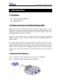
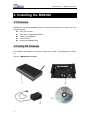
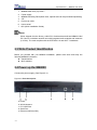
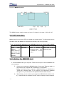
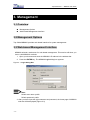
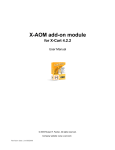
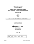
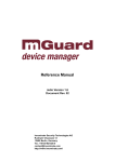
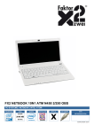
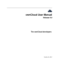
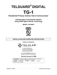
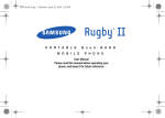
Top Global Wireless LAN MobileBridge™ User Guide Top Global USA, Any modification of this product will not issue a separate notice. All Rights Reserved. Rev 3.5 English Edition, 3 17 2007 Top Global USA. ----MB8000 User Guide CONTENT FOREWORD .................................................................................. 4 OBJECTIVES .............................................................................................................................. 4 AUDIENCE ................................................................................................................................. 4 CONVENTIONS .......................................................................................................................... 4 OBTAINING DOCUMENTATION ................................................................................................ 4 WORLD WIDE WEB .................................................................................................................. 4 1. INTRODUCTION ........................................................................ 5 1.1 OVERVIEW .......................................................................................................................... 5 1.2 ADVANCED FEATURES OF MOBILE BRIDGE 8000 ............................................................ 5 1.3 NETWORK ARCHITECTURE ............................................................................................... 5 1.4 SPECIFICATION ................................................................................................................... 6 2. INSTALLING THE MB8000 ....................................................... 7 2.1 OVERVIEW .......................................................................................................................... 7 2.2 VERIFY KIT CONTENTS...................................................................................................... 7 2.3 WRITE PRODUCT IDENTIFICATION ................................................................................... 8 2.4 POWER UP THE MB8000 .................................................................................................... 8 2.5 LED INDICATORS ............................................................................................................... 9 2.6 INITIALIZE THE MB8000 UNIT .......................................................................................... 9 3. MANAGEMENT ....................................................................... 13 3.1 OVERVIEW ........................................................................................................................ 13 3.2 MANAGEMENT OPTIONS .................................................................................................. 13 3.3 WEB-BASED MANAGEMENT INTERFACE ........................................................................ 13 3.3.1 STATUS ........................................................................................................................... 14 3.3.2 BASIC .............................................................................................................................. 14 3.3.2.1 WIRELESS INTERNET ................................................................................................. 15 3.3.2.2 LOCAL IP CONFIGURATION ........................................................................................ 17 3.3.2.3 WLAN CARD .............................................................................................................. 18 3.3.3 ADVANCED ..................................................................................................................... 19 3.3.3.1 PASSWORD ................................................................................................................. 20 -1- Top Global USA. ----MB8000 User Guide 3.3.3.2 ENCRYPTION .............................................................................................................. 21 3.3.3.3 RADIUS AUTHENTICATION ......................................................................................... 23 3.3.3.4 RADIUS ACCOUNTING ................................................................................................ 26 3.3.3.5 FILTERS ...................................................................................................................... 27 3.3.3.6 WEB PORTAL.............................................................................................................. 27 3.3.3.7 IP PORT FORWARDING .............................................................................................. 29 3.3.3.8 LINK INTEGRITY .......................................................................................................... 31 3.3.3.9 DYNAMIC DNS ........................................................................................................... 31 3.3.3.10 GREETING PAGE ...................................................................................................... 32 3.3.3.11 GPS.......................................................................................................................... 33 3.3.3.12 HOW TO USE MB8000 AS A BRIDGE ...................................................................... 34 3.3.3.13 STATIC ROUTE .......................................................................................................... 35 3.3.3.14 PPP .......................................................................................................................... 35 3.3.3.15 REDIRECTION(SMTP AND HTTP) .......................................................................... 36 3.3.3.16 GRE TUNNELLING ................................................................................................... 37 3.3.3.17 WALLED GARDEN .................................................................................................... 37 3.3.4 TOOLS ............................................................................................................................ 37 3.3.4.1 DOWNLOAD & UPLOAD .............................................................................................. 38 3.3.4.2 REBOOT...................................................................................................................... 39 3.3.4.3 RELOAD ...................................................................................................................... 40 3.3.5 MONITOR ....................................................................................................................... 40 3.3.5.1 WAN ............................................................................................................................ 41 3.3.5.2 ROUTER...................................................................................................................... 41 3.3.5.3 SYSTEM LOG .............................................................................................................. 41 3.3.5.4 LINK STATUS .............................................................................................................. 41 3.3.6 WIZARD .......................................................................................................................... 41 3.3.7 PIN & PUK .................................................................................................................... 43 4. SECURE SOCKET LAYER (SSL) ........................................... 45 4.1 OVERVIEW ........................................................................................................................ 45 4.2 INTRODUCTION TO SSL ................................................................................................... 45 4.3 SERVER CERTIFICATE AND PRIVATE KEY DOWNLOAD FOR MB8000 ......................... 45 4.4 CA CERTIFICATE DOWNLOAD FOR MB8000 ................................................................. 46 4.5 CA CERTIFICATE INSTALL FOR MB8000’S CLIENT ...................................................... 47 4.6 CA CERTIFICATE UNINSTALL FOR MB8000’S CLIENT ................................................. 50 5. TROUBLESHOOTING ............................................................. 51 5.1 OVERVIEW ........................................................................................................................ 51 5.2 INTRODUCTION ................................................................................................................. 51 5.3 RESET TO FACTORY DEFAULT PROCEDURE .................................................................. 51 -2- Top Global USA. ----MB8000 User Guide 5.4 FORCED RELOAD PROCEDURE ........................................................................................ 52 5.5 FIRMWARE UPGRADE PROCEDURE THROUGH WEB...................................................... 53 5.6 SCAN TOOL UTILITY......................................................................................................... 53 6. DEFAULT MB8000 SETTINGS ............................................... 57 FEDERAL COMMUNICATION COMMISSION INTERFERENCE STATEMENT................................................................................ 58 -3- Top Global USA. ----MB8000 User Guide Foreword This section describes the objectives, audience and conventions of the Top Global MB8000 User Guide. Objectives This document explains the steps for initial setup and basic configuration of the MB8000. This document also provides troubleshooting information and detailed specifications. Audience This document is for the person installing and configuring the Top Global MB8000 for the first time. The installer should be familiar with network structures, terms, and concepts. Conventions This document uses the following conventions to convey instructions and information: ■ Tools and keywords are in boldface type. Means reader take note. Notes contain helpful suggestions or references to materials not contained in this manual. Note The warning symbol means attention. Pay attention to the contents following after this symbol, wrong operation may cause damage to the device. Warning Obtaining Documentation The following sections explain how to obtain documentation from Top Global. World Wide Web You can access the most current Top Global documentation on the World Wide Web at the following URL: http://www.topglobalusa.com/support1.asp -4- Top Global USA. ----MB8000 User Guide 1. Introduction 1.1 Overview Advanced Features of MB8000 Network architecture Specification 1.2 Advanced Features of Mobile Bridge 8000 MB8000 has the most state-of-the-art system architecture design based on its rich network protocol features, reliable system level performance, optimized hardware design architecture, solid wireless security algorithms, and competitive product price. It is a leading MobileBridge™ design in the industry. People can access network resources anytime anywhere by using this technology. MB8000 is the first wireless product combining WLAN with GPRS/EDGE/UMTS, and CDMA 1x/EVDO. TOP Global MB8000 supports ESSID suppression, WEP (RC4) encryption, 802.1x port-based authentication and WPA. MB8000 offers the secure “Always on, anywhere, anytime” wireless connectivity to subscribers. It also supports VPN and gives the user maximum security. RADIUS Client in MB8000 supports various accounting methods. Operators and WISPs could choose their preferred business model and accounting policies. 1.3 Network Architecture Figure 1-1 Illustrates a typical configuration for internet access via MB8000. Figure 1-1 Standalone wireless network access infrastructure -5- Top Global USA. ----MB8000 User Guide 1.4 Specification Table 1-1 Mobile Bridge Specifications Category Specification Hardware Dimensions (HXWXL) 2.7 cm X 13 cm X 25.4cm 1.1 in X 5.1in X 10 in Weight 895g(1.97 lbs) Power 100/240 VAC high quality and worldwide safety approval Operating 0° to 50°C (32° to 122°F) @ 20 to 90% relative humidity Transport -40° to 60°C (-40° to 140°F) @ 15 to 95% relative humidity (no condensation allowed) Storage -10° to 60°C (14° to 140°F) @ 10 to 90% relative humidity (no condensation allowed) Ethernet interface One 10/100 Base-T, RJ-45 female socket Wireless interface IEEE 802.11b, MiniPCI slots for radio NIC PC CARD interface One PC card slot for Wireless Wide Area Network (WWAN) including: GPRS / EDGE/ UMTS and CDMA1x / EVDO networks Serial interface 4 LEDs MTBF(Mean Time Between Failures) 8-Pin Female MiniDin RS232 connector Power WLAN Wireless Wide Area Network (WWAN) Ethernet Activity port (LAN) 244,048Hrs Software z z z z z -6- Boot Loader and Power On Self Tests (POST) MB8000 executable program (MB8000 Firmware) CLI compatible with generic Telnet and Terminal clients. Serial port Interface is compatible with most ASCII terminal programs (such as HyperTerminal) HTTP Interface compatible with web browsers equivalent to Microsoft Internet Explorer 4.0 and Netscape 4.0 and higher. Top Global USA. ----MB8000 User Guide 2. Installing the MB8000 2.1 Overview Installing the Top Global MB8000 is easy. Follow the quick steps below to power up your wireless network: Verify kit Contents. Write down Product Identification. Power up the MB8000. LED Indicators Initialize the MB8000 Unit 2.2 Verify Kit Contents Your MB8000 kit includes the following components, similar to those depicted in Figure 2-1. Figure 2-1 MB8000 Kits Contents -7- Top Global USA. ----MB8000 User Guide 1. 2. 3. 4. 5. 6. 7. MB8000 Main Unit (Top View) Power supply MB8000 Mounting Rack (Back View, optional and can be purchased separately) CD Cross-over cable User manual QIG (Quick Installation Guide) Note: When shipped from the factory, a Mini-PCI Card has been built into MB8000. Mini PCI Card is a wireless network card with integrated radio modules and antennas (2.4 GHz). The card complies with the IEEE 802.11b and Wi-Fi™ standards. 2.3 Write Product Identification Before you proceed with your MB8000 installation, please write down and keep the following MB8000 information. z Serial Number z MAC address 2.4 Power up the MB8000 Connect the power supply. (See Figure 2-2). Figure 2-2 Ports description a. Power b. WLAN Antenna c. PC CARD Slot d. Serial Port e. Ethernet Interface(LAN) -8- Top Global USA. ----MB8000 User Guide Figure 2-3 MB8000 Top View The MB8000 power supply accepts any input AC voltage in the range of 100-240 VAC. 2.5 LED Indicators MB8000 has four two-color LEDs to indicate the working status. The follow table shows the status when the MB8000 is configured successfully and running properly. Table 2-1 Normal LED Indications (Use WWAN to Connect to Internet and No WAN) Power Green when MB8000 is ready. Red if an error occurs. For example, corrupt firmware. WLAN Green blink WWAN LAN Green if WWAN is transferring data. Red if WWAN is in error status. Green blink if LAN is transferring data. 2.6 Initialize the MB8000 Unit 1. Connect MB8000 with your computer. There are two ways to connect MB8000 with your computer: -9- I. Connect your computer to MB8000 using a “Cross-over” Ethernet cable or a hub and set your computer with “Automatic IP” configuration. Note:If you connect your computer to MB8000 directly, you should use a “Cross-over” Ethernet cable. If you connect your computer to MB8000 through a hub, you should have two parallel Ethernet cables at least. II. Alternatively, you can connect your computer to MB8000 with wireless LAN. a) Install an 802.11b wireless LAN PC card in a laptop or other computer, Top Global USA. ----MB8000 User Guide b) including the driver and the Client Manager Application software if available. If you are using a Centrino laptop, the wireless LAN module is already embedded. There is no need to install extra wireless LANPC card. Configure the wireless LAN card to match the network name and encryption key of wireless LAN card installed in the MB8000. The default network name is “Topglobal-XXXXXX”, XXXXXX is the same as the right six characters of serial number. “Automatic IP” configuration is also needed. 2. Validate that your computer has got IP address from the MB8000, then open the web browser and enter http://172.16.0.1. Press Enter then the MB8000 login screen appears. Enter the username/password (default is public/public), and click OK, the web configuration screen appears. Figure 2-4 Web GUI login window - 10 - Top Global USA. ----MB8000 User Guide Figure 2-5 Home Page There are two buttons on the home page: Wizard and Customize. Alternatively, you can configure your MB8000 by using them. If you are using the Wizard to configure the MB8000, please continue with the remaining part of this section. If you are using Customize to configure the MB8000, please jump to the chapter 3--Management. 3. Change the Dialing Up parameters of WWAN card if needed Click button “Wizard” on the home page. The following configuration page appears (use CDMA 1x/EVDO for example). Figure 2-6 Wizard--Wireless Wan Change “Card Status” to “Enable”, type correct “Phone Number”, “User Name” and “Password” (If you are using a GPRS/UMTS/EDGE/HSDPA network, you will need to - 11 - Top Global USA. ----MB8000 User Guide input “CID”, “APN”), then click button “Next”, the following configuration page appears. Figure 2-7 Wizard--Wireless connect Click button “Connect” and wait a moment, a page will appear to tell you the results. Figure 2-8 Wizard -connection result Congratulations! Now you can access internet through MB8000. - 12 - Top Global USA. ----MB8000 User Guide 3. Management 3.1 Overview Management Options Web-based Management Interface 3.2 Management Options Top Global MB8000 provides web-based interface for system management. 3.3 Web-based Management Interface MB8000 embeds a web server for web-based management. This section will show you how to visit MB8000’s web site. 1. Open your browser and enter the MB8000’s IP address in the address bar. 2. Press the ENTER key. The MB8000 Login dialog box appears. Figure 3- 1 Login Dialog Box Note: Default user name: public Default password: public 3. After you have input the right username and password, the home page of MB8000 web site will be displayed (Figure 3-2). - 13 - Top Global USA. ----MB8000 User Guide Figure 3- 2 MB8000’s home page There are three main categories of MB8000’s web site: status, wizard and customize. The following section will explain each of them in detail. 3.3.1 Status View your system information in status area. The status area includes two sub-areas: system status and system logs. — System status provides system level information, including the MB8000’s IP address and contact information. — System logs including some system traps, report important events to the network management stations. Each log identifies a specific severity level. For more information about system traps, refer to “Troubleshooting” of the user guide. 3.3.2 Basic Basic part includes the most primary configurations for MB8000. There are three main categories of basic settings: Wireless Internet Local IP Configuration WLAN Card - 14 - Top Global USA. ----MB8000 User Guide 3.3.2.1 Wireless Internet Configuration varies by wireless card. type is CDMA. As Figure 3-3 shows, the wireless card’s Figure 3- 3 wireless Internet z z z z z z z z z z z z - 15 - Card status: Enable or disable the wireless card status. When CDMA and EVDO card is used, the default value is Enabled, otherwise , Disabled. Connect Type: Indicates the wireless card’s type: CDMA, EVDO, GPRS, or UMTS. Phone Number: This parameter is used to provide a phone number for modem. User Name: This parameter is used to provide a user name for modem. Password: This parameter is used to provide a password for modem. Init string: This parameter is used to provide an initialization string for modem. Dial Mode: Dial on demand or dial on startup, the default value is dial on startup. Auto Disconnect Timer: The time in minutes for the MB8000 automatically disconnect from Internet if no data transmission between MB8000 and Internet when MB8000 in Dial on demand mode. The default value is 30. Remote IP Negotiation: Enable or disable MB8000 to negotiate with service provider to get peer IP address. Primary DNS Negotiation: Enable or disable MB8000 to negotiate with service provider to get primary DNS address. Secondary DNS Negotiation: Enable or disable MB8000 to negotiate with service provider to get secondary DNS address. Local WAN IP Negotiation: Enable or disable MB8000 to negotiate with service provider to get local WAN IP address. Top Global USA. ----MB8000 User Guide z z z z 1. Static IP Address: When LOCAL WAN IP Negotiation is disabled, MB8000 will use Static IP Address as PDP address. Connect: connect to Internet. Disconnect: disconnect to Internet. Submit: submit and save the parameters. If wireless card type is GPRS, EDGE, UMTS or HSDPA, the parameters to be configured are shown as Figure 3-4. Figure 3- 4 wireless Internet z z z - 16 - APN: (Access Point Name) A string parameter, which is a logical name that is used to select the GGSN or the external packet data network. CID: (PDP Context Identifier) A numeric parameter, which specifies a particular PDP context definition. PDP Address: A string parameter that identifies the MB8000 in the address Top Global USA. ----MB8000 User Guide z 2. space applicable to the PDP. AT Command: This parameter is used to initialize modem with some AT commands. If wireless card type is absent, page shown to users likes Figure 3-5. Figure 3- 5 No card 3.3.2.2 Local IP Configuration IP Configuration z Local IP Address: This parameter represents the IP Address of the LAN & WLAN. The default IP address is 172.16.0.1. z Local IP Mask: This parameter represents the subnet mask of the LAN & WLAN. The default subnet mask is 255.255.0.0. DHCP Server z DHCP Server Status: This parameter indicates whether the DHCP server is enabled or disabled in MB8000. If DHCP is disabled, each client device must be manually configured. z Start IP Address: The start IP address for the DHCP IP address pool. z Width of IP Address: The DHCP IP address pool range. z Default Lease Time: The default lease time in seconds for the IP address assigned by the DHCP server to the DHCP client. z Maximum Lease Time: The maximum lease time in seconds for the IP address assigned by the DHCP server to the DHCP client. DNS Configure DNS Relay, also called DNS Redirect or DNS Proxy, allows clients on the local network to use the gateway as their primary DNS server. In this way, all DNS queries from clients are sent to MB8000 and then automatically forwarded to your ISP's DNS servers by MB8000. This allows clients to always be able to use the gateway as their DNS server regardless of changes in DNS server that your ISP may make in the future. z - 17 - DNS Relay Status: This parameter indicates whether DNS relay is enabled or disabled. Top Global USA. ----MB8000 User Guide z z Primary DNS IP Address: This parameter represents the IP address of the primary DNS server. Secondary DNS IP Address: This parameter represents the IP address of the secondary DNS server. User can change primary or secondary DNS IP address manually. To make the change work persistently, user should disable PPP DNS negotiation (refer to 3.3.2.1 Wireless Internet). Figure 3- 6 Local IP Configuration 3.3.2.3 WLAN Card z z z - 18 - Wireless card status: This parameter indicates whether wireless card is enabled or disabled. Network Name: Network name for each mini-PCI Card. The default value is Topglobal-XXXXXX, XXXXXX is the same as the last six characters of serial number. Frequency Channel: The desired frequency channel for card. Ensure that the nearby devices do not use it. Top Global USA. ----MB8000 User Guide z z z Closed System: A closed system means that only clients who know the MB8000’s network name can access MB8000’s wireless network. When this parameter is set to Enable, MB8000 will not broadcast MB8000’s network name. When this parameter is set to Disable, MB8000 will broadcast MB8000’s network name so client can scan the name. IBSS Relay Status: This parameter indicates whether IBSS Relay Status is enabled or disabled. MAC Address: Show the WLAN card’s MAC address. Figure 3- 7 Wi-Fi Card 3.3.3 Advanced - 19 - Password Encryption Radius Authentication Radius Accounting Filters Web Portal IP Port Forwarding Link Integrity Dynamic DNS Greeting GPS Static Route PPP Walled Garden Redirection GRE Top Global USA. ----MB8000 User Guide 3.3.3.1 Password z z z z z z z z z z z Http Status: This parameter indicates whether http server is enabled or disabled. Http User Name: User name for MB8000’s web administration. Http Password: Password for MB8000’s web administration. Http port: The port of HTTP server. Telnet Status: This parameter indicates whether telnet server is enabled or disabled. Telnet port: The port of telnet server. Telnet Password: Password for MB8000’s telnet server. SNMP Password: Read password and read/write password for MB8000’s SNMP agent. Remote Management: Enable remote management client to be able to manage MB8000. Status: This parameter indicates whether Remote Management is enabled or disabled. Remote Address: The address of remote management server. Interval: The interval to inform remote management server. Trap Hosts: This parameter sets the IP address of the trap host, then the traps about MB8000 will be send to these IP address. Trap Hosts: This parameter sets the IP address of the trap host, then the traps about MB8000 will be send to these IP address. Add an Entry to the Trap Hosts Table 1. Click the “Add” button in the Trap Hosts table. 2. Enter the IP Address of a client station. 3. Add a comment as needed. Entries are automatically enabled. Disable or Delete an Entry in Trap Hosts Table 1. Click the Edit button in the Trap Hosts table. 2. Select the entry you want to disable or delete 3. Click OK - 20 - Top Global USA. ----MB8000 User Guide Figure 3- 8 Password 3.3.3.2 Encryption Encryption configuration is used to set over-the-air encryption properties for WLAN card. Available security protocol used in MB8000 includes 802.1x, WPA and WEP. z Network Authentication: Open: Shared: 802.1x Only (Non-WPA): 802.1x and WEP (Non-WPA): WPA: WPA-PSK: This parameter sets the authentication mode. “Open” means setting the authentication mode to open-system authentication. Under this mode, stations can associate to the MB8000 freely. “Shared” means setting the authentication mode to shared-secret authentication. Under this mode, stations can associate to the MB8000 with the proper WEP keys. “802.1x Only (Non-WPA)” means that the MB8000 uses IEEE 802.1x to perform the authentication. Stations which failed to pass the 802.1x authentication will be denied to access the MB8000. “802.1x and WEP (Non-WPA)” means that the stations which success in either the WEP authentication or 802.1x authentication will be allowed to access the MB8000. “WPA” means that the MB8000 uses WPA with the backend authentication sever to authenticate the stations. “WPA Pre-Shared Key” means that the MB8000 uses WPA authentication with the - 21 - Top Global USA. ----MB8000 User Guide Pre-Shared Key to authenticate the users. To use WPA PSK mode, you should configure MB8000 as following: 1. Set "Network Authentication" to "WPA-PSK"; 2. Set "Data Encryption" to "TKIP"; 3. Set "Deny Non-Encryption Data" to "Disable"; 4. Set "WPA Pre-Shared Key" with a pass-phrase (min 8 max 63 characters); z Data Encryption: This parameter sets the data encryption type. “Disabled” means that no encryption is used in the traffic between the MB8000 and the stations. “WEP” means that the traffic data is encrypted by WEP. “TKIP” means that TKIP is used in the traffic. z z Key length: There are two options you can select to decide the WEP key length. Encryption Key: These parameters are used as WEP keys. Deny Non-Encrypted Data: Select Enable to prevent use of non encrypted data, or select Disable to allow non-encrypted data. z Encrypt Data Transmissions Using: Indicates which WEP key ID is selected to encrypt the outgoing data. z 802.1x Re-Authentication Interval: The 802.1x Re-Authentication Interval field is an integer, which indicates that how long the 802.1x authenticator will issue a re-authentication request in second. The minimal is 600, and the default value is 600. z Note: The range of this value is from 600 to 65535. z WPA Group Key Renewal: This field is an integer, which indicates that the interval of TKIP key to renew. The minimal is 300. z WPA Pre-Shared Key (passphrase): The WPA Pre-Shared Key field, which is to be filled with WPA-PSK, it’s a string of “pass-phrase”, whose length ranges from 8 to 64 octets. - 22 - Top Global USA. ----MB8000 User Guide Figure 3- 9 Encryption 3.3.3.3 Radius Authentication A RADIUS server is one that contains central user databases which can be used to identify which user is allowed to access the wireless network. The information for primary RADIUS server is mandatory if RADIUS is enabled. The information for backup RADIUS server is optional. z z z z z z z z - 23 - RADIUS MAC Access Control Status: This parameter indicates whether user authentication by RADIUS is enabled or disabled. Interface: The network interface that will be used for communicating with RADIUS server. Authentication Lifetime (minutes): The time before when auto re-authentication will be performed. The default value is 15 minutes. Server Status: The status of RADIUS server. IP Address: The IP address of RADIUS server. Destination Port: The listen port of RADIUS server. The default value is 1812. Response Time (sec): The maximum time to wait for the authentication response from RADIUS server. Shared Secret: Shared secret between RADIUS server and MB8000. Top Global USA. ----MB8000 User Guide z Maximum retransmissions: The maximum authentication may be retransmitted. number of times when Figure 3- 10 Radius Authentication Configurations Note: For RADIUS authentication interface, there are two options to be selected: ---LAN: see Figure3-11 for the proper connection. ---WWAN: see Figure3-12 for the proper connection. - 24 - an Top Global USA. ----MB8000 User Guide Figure 3- 11 Radius on LAN Figure 3- 12 Radius on WAN - 25 - Top Global USA. ----MB8000 User Guide 3.3.3.4 Radius Accounting z z z z Server Status: The status of RADIUS server. IP Address: The IP address of RADIUS server. Destination Port: The listening port of RADIUS server. The default value is 1813. Response Time (sec): The maximum time to wait for the response from RADIUS server. Note: The range of this value is from 1 to 10. z z z Shared Secret: This is the shared key between RADIUS server and MB8000. Accounting Interim Update Interval: This parameter indicates the Interim update interval of the accounting. Maximum retransmissions: The maximum number of times that an accounting may be retransmitted. Note: The range of this value is from 1 to 4. Figure 3- 13 Radius Accounting - 26 - Top Global USA. ----MB8000 User Guide 3.3.3.5 Filters The MAC access section allows you to add, edit or delete users who can access MB8000. Users are identified by their MAC address. z Access control Status: This parameter indicates whether access control by MAC address is enabled or disabled. z Access control Operation Type: Choose between Allow and Deny. This determines how the stations identified in MAC Access Table are filtered. Add an Entry to the MAC Access Control Table 1. Click the Add button in the MAC Access Control table. 2. Enter the MAC Address of the client station. 3. Add comment (optional). 4. This entry is automatically enabled. Disable or Delete an Entry in the MAC Access Control Table 1. Click the Edit button in the MAC Access Control Table. 2. Select the MAC Address you want to disable or delete 3. Click OK The Private network filter is used to prevent some packets from being sent to Internet, which destination IP address are in the private network range. z Status: This parameter indicates whether this filter is enabled or disabled. Figure 3- 14 Filters 3.3.3.6 Web Portal Web portal is an authentication method which authenticates users by requiring them to - 27 - Top Global USA. ----MB8000 User Guide input user name and password on web pages. Web Portal Figure 3- 15 Web Portal z Web Portal Status: This parameter indicates whether web portal is enabled or disabled. z Alive Timeouts (Seconds): The idle time, user idle more than this time will be automatically kicked out by MB8000. Local User Base Setting The local user base section allows you to add, edit or delete items which are used to validate the Web Portal local authentication. z Local User Base Status: This parameter indicates whether local user authentication is enabled or disabled. Add an Entry to the Local User Base Click the Add button in the Local User Base table. Enter the user name and password for each user. Enter entry up-rate and down-rate for each user for the sake of flow control. Disable or Delete an Entry in the Local User Base Table 1. Click the Edit button in the Local User Base Table. - 28 - Top Global USA. ----MB8000 User Guide 2. Select the user entry you want to disable or delete 3. Choose “Disable” or “Delete” in the user’s entry status. 4. Click OK When web portal status is enabled, a login page will be shown to the users who want to access Internet through MB8000. This page likes figure 3- 16 . Users can customize the login page through setting greeting page configurations (refer to 3.3.3.10 Greeting Page). Figure 3- 16 WEB Portal Login Page 3.3.3.7 IP Port Forwarding To make the internal machine's service available to the outside, we need to use port forwarding on the gateway server. It is assigning a port on the gateway to accept all connections and forward it to the internal machines port where the service is listening. . For example: Let xxx.xxx.xxx.xxx be the IP address of the gateway server connected to the internet and 172.16.0.100 be the IP address of the internal machine. And you want to run a web server on 172.16.0.100 on port 80 which should be available to the outside internet. We can forward the port 50000 on xxx.xxx.xxx.xxx to port 80 of 172.16.0.100 Source: xxx.xxx.xxx.xxx:50000 -- forwarded to -> 172.16.0.100:80 - 29 - Top Global USA. ----MB8000 User Guide There are two IP Port Forwarding tables in this configuration for inputting items for “IP port forwarding”. In the default settings, the two tables are empty. Click on “Add” and “Edit” button can pop up windows for editing the tables. Figure 3- 17 IP Port Forwarding Table z Add an Entry to the IP Port Forwarding Control Table 1. Click the “Add” button in the TCP or UDP table. 2. Enter the Local IP Address of the client station. 3. Enter the Local Port Number of the client station. 4. Enter Global Port Number. 5. Add a comment as needed. Entries are automatically enabled. z Disable or Delete an Entry in IP Port Forwarding Control Table 1. 2. 3. Click the Edit button in the TCP or UDP Table. Select the entry you want to disable or delete Click OK Bridge Mode: When bridge mode is enabled, MB8000 works as a bridge. That is, MB8000 forwards incoming and outgoing packets, doesn’t modify anything about them. We will discuss it in section How to Use MB8000 as A Bridge(3.3.3.12). z z - 30 - Bridge Mode: Indicates users which bridge mode will be used. When Enable with Static MAC is selected, users should assign a client’s MAC address to MB8000. When Enable with Dynamic MAC is selected, MB8000 gets client’s physical address automatically. MAC Address: Client’s physical address. Top Global USA. ----MB8000 User Guide 3.3.3.8 Link Integrity This function is used to verify the link status of WWAN. If the link of WWAN is down, WWAN LED will become orange and WWAN will try to reconnect. z z z Link Integrity Status: This parameter is used to enable or disable the link integrity functionality. Link Poll Interval: This parameter is used to set the poll interval (in milliseconds) for the link integrity check. Link Poll Retransmissions: This parameter is used to set the number of retransmissions for the link integrity check. Figure 3- 18 Link Integrity 3.3.3.9 Dynamic DNS MB8000 offers a Dynamic Domain Name System (DDNS) feature. DDNS lets you assign a fixed host and domain name to a dynamic Internet IP address. It is useful when you are hosting your own website, FTP server, or other server behind the Router. Before you can use this feature, you need to sign up for DDNS service at a website of a service provider. Status: This displays the status of the DDNS connection. Provider: From this pull-down menu, select the DDNS service with which you have membership. User Name: Enter the User Name for your DDNS account. Password: Enter the Password for your DDNS account. Host Name: A domain name which registered at www.Dyndns.org. Wildcard Status: Enable or Disable wildcard feature. The wildcard aliases *.yourhost.ourdomain.tld to the same address as yourhost.ourdomain.tld. Figure 3- 19 DDNS - 31 - Top Global USA. ----MB8000 User Guide 3.3.3.10 Greeting Page When greeting page function is enabled, a greeting page will be shown to the users who want to access Internet through MB8000. Users cannot access Internet until they click “OK” at this page. The content of greeting page can be customized through WEB browser. Figure 3- 20 Greeting Page Configurations Greeting page setting z Greeting Page Status: Enable or disable greeting page function. z Greeting Timer: When this timer has expired, a greeting page will be shown to users again who are accessing Internet through MB8000. Also, Users should - 32 - Top Global USA. ----MB8000 User Guide z z z z z click “OK” again to access Internet. Greeting Header: A header at greeting page. Greeting Sub Header: A sub header at greeting page. Greeting body: The primary content of greeting page. The maximum characters you can enter is 768. Greeting Footnote: An HTTP link. Logo File: An image of GIF format,The maximum size is 20K. A greeting page shown to users likes the following: Figure 3- 21 Greeting page 3.3.3.11 GPS MB8000 supports a specific GPS service. If you want to use this application, you need to buy a GPS module designed by Top Global firstly. MB8000 can forwards the GPS tracking DATA to Xora server via your WWAN interface. About the Xora service, please refer to http://www.xora.com for the detail. z z z z z z - 33 - GPS Status: Enable or disable GPS function. Baud rate: The rate for communication between GPS module and MB8000. Serial Number: Xora user account. Server IP: The IP address of Xora server. Server Port: The UDP port of Xora Server. Interval: The interval of sending out GPS data. Top Global USA. ----MB8000 User Guide Figure 3- 22 GPS 3.3.3.12 How to use MB8000 as A Bridge 1. Network Architecture In this architecture, Router is a client when connected to the Ethernet port of MB8000, MB8000 forwards packets form router to Internet or from Internet to router, doesn’t modify anything about these packets. Bridge mode is used only in few occasions, such as VPN connection between a router and another router. The WLAN of MB8000 is disabled when bridge mode is enabled. Figure 3- 23 Bridge Mode Architecture 2. The parameters of bridge mode should be configured in MB8000 (refer to 3.3.3.7 IP Port Forwarding ). 3. The DHCP default lease time should be set to 30 seconds or shorter time (refer to 3.3.2.2 Local IP Configuration) 4. Reboot MB8000 5. Set Router with “Automatic IP” configuration - 34 - Top Global USA. ----MB8000 User Guide 6. Waiting about 30 seconds, a connection to Internet can be established. 3.3.3.13 Static route A static route is a route that is created manually by a network administrator. MB8000 supports static route. User should not add a static route to WWAN. z Status: Enable or disable static route function. Figure 3- 24 Static router z z z z Destination: The destination IP address. Mask: The destination IP mask. Gateway: The gateway IP address. Status: Enable or disable this route. 3.3.3.14 PPP Users can configure some PPP negotiation options. z Local ACCM Negotiation Status: Indicates whether MB8000 negotiates ACCM with peer. z z Local ACCM: The value of local ACCM. Local PFC Negotiation Status: Indicates whether MB8000 negotiates PFC with peer. z Local ACFC Negotiation Status: Indicates whether MB8000 negotiates ACFC with peer z Local VJC Negotiation Status: Indicates whether MB8000 negotiates VJC with peer z Remote VJC Negotiation Status: Indicates how MB8000 to response the negotiation request from peer. - 35 - Top Global USA. ----MB8000 User Guide Figure 3- 25 PPP Advanced settings 3.3.3.15 Redirection(SMTP and HTTP) SMTP Redirection allows you to relay incoming mail to a mail server on a non-standard port. This is quite useful for those who want to run a mail server but are stuck with an ISP that blocks inbound port 25, the standard mail port. MB8000 also supports HTTP redirection. z Status: Enable or disable the redirection service. Figure 3- 26 Redirection z z z - 36 - Destination Port: The Port will be redirected. Redirection IP: The IP address of a server will be redirected to. Redirection Port: The port of a server will be redirected to. Top Global USA. ----MB8000 User Guide 3.3.3.16 GRE tunnelling MB8000 supports GRE tunnels. z Status: Enable or disable the GRE services Figure 3- 27 GRE tunnelling z Local subnet Address and local subnet Mask: The Local network is the computer(s) on your LAN that can access the tunnel. z Remote subnet Address and remote subnet Mask: The Remote network is the computer (s) on the remote end of the tunnel that can access the tunnel. z Remote Gateway Address: The Remote Gateway is a device that supports GRE tunnel on the remote end of the tunnel. z Status: Select Enable to enable the tunnel. 3.3.3.17 Walled Garden Please refer to the document How to configure the TOP Global MB8000 for using Remote portal &Walled Garden 3.3.4 Tools Tools provide functionalities including files downloading/uploading, MB8000 rebooting or reloading control. - 37 - Top Global USA. ----MB8000 User Guide 3.3.4.1 Download & Upload Download and upload tools enable files downloading or uploading between MB8000 and TFTP server. TFTP server could be a computer with TFTP server software. TFTP server can be freely downloaded from www.solarwinds.net. You can also search other free TFTP server in the internet. Files downloadable includes configuration file (Config), MB8000 Image(Img), logon web page(BspBl), server certificate file(ServerCert), server private key file(PrivateKey) and Certificate Authority certificate file(CAcert). Files uploadable includes configure file (Config). Note: 1) A TFTP server must be running and configured to point to the directory containing the target file. If you don’t have a TFTP server installed on your system, install the TFTP server first. 2) Before you can download or upload file successfully, you must make sure that the physical connection was exited between the TFTP server and the corresponding interface in the same subnet. — Server IP Address. The IP address of TFTP server. — File Name. Name of the target file. — File Type. Type of the target file. Possible file type includes: — Config. Configuration file containing information such as system name and contact name. — BspBl. Upgraded bootloader. — Img. MB8000 Image (executable program). — ServerCert. Server certificate file(.pem file). — PrivateKey. Server private key file(.pem file). — Cacert. Certificate Authority certificate file(.cer file). — File Operation. File operation type including Download, Upload or Download & Reboot. Download means from computer to MB8000. Upload means from MB8000 to computer. You should reboot the MB8000 after downloading files. Figure 3- 28 Download & Upload - 38 - Top Global USA. ----MB8000 User Guide Users can also download firmware from local or remote FTP server using FTP client in MB8000. Figure 3- 29 Download –FTP Server IP Address: The IP Address of FTP server. File Name: The firmware name that is located at root directory of FTP server. User Name: User name Password: Password 3.3.4.2 Reboot Reboot operation saves configuration changes (if any) before resetting the MB8000 (this function can also be accomplished by holding down the Reset button). Set the time to Reboot as zero will cause an immediate reboot. Note: After configured all the parameters you need, reboot the MB8000.All the configuration will become effective. Figure 3- 30 Reboot - 39 - Top Global USA. ----MB8000 User Guide 3.3.4.3 Reload Reload operation restores the MB8000 configuration to factory default values. The MB8000 may also be reloaded from the RELOAD button on indicator side of the unit. Press and hold the RELOAD button for more than 30 seconds, until all the indicator lights turn off. Then release RELOAD button, press the RESET button to set up the device again. Since this will reset the current MB8000 IP address, a new IP address must be assigned. For more information, please refer to “Initialization”. Users can also reload an MB8000 through WEB GUI. Figure 3- 31 Reload Warning: If you press and hold the RELOAD button for more than 15 seconds immediately after the MB8000 is power on or reset, the MB8000 will enter into Force Reload Procedure. The software in the MB8000 will be erased. You will have to download software into MB8000 to make it work again. For more information, please refer to “Force Reload Procedure”. 3.3.5 Monitor Monitor provides tools including link activity test, WAN interface monitoring and router table monitoring. There are three sub-areas of monitor: Wan Router System Log Link status - 40 - Top Global USA. ----MB8000 User Guide 3.3.5.1 Wan WAN interface monitoring tool shows whether WAN interface works normally or not .If the address is valid; the interface works normally, otherwise abnormally. 3.3.5.2 Router Router shows the route table of MB8000. 3.3.5.3 System Log Show system log information. 3.3.5.4 Link Status Link tests whether a link is active by pinging the target IP address. Depending on whether the target IP address is available, the result will show alive or not alive Figure 3- 32 Link status 3.3.6 Wizard The Setup Wizard will guide you step-by-step to configure your MB8000 for use with your wired WAN and wireless WAN. Step1. Configure your wireless internet card in the first step. When you click on the “Wizard” Button, the first page will show your different wireless internet configuration page according to your card. 1. - 41 - If no card has been inserted into the slot or MB8000 can not identify the card, the following information will be prompted. Top Global USA. ----MB8000 User Guide Figure 3- 33 No card 2. If you are using CDMA/EVDO card, then the following page will be shown to you: Figure 3- 34 CDMA 3. If you are using GPRS/EDGE/UMTS/HSDPA card, then the following page will be shown to you : Figure 3- 35 GPRS Finish the configuration of the wireless internet, click on “Next”, to the next step. Step2. Connect Click on “Connect” button. If you have already connected to the wireless Internet when - 42 - Top Global USA. ----MB8000 User Guide you first reboot the MB8000, then you will be prompted not to connect again. Otherwise, you will wait for about 1 minute until MB8000 has finished dialing-up. Figure 3- 36 Connected Step3. Result Finally, MB8000 will give the connection result. If MB8000 failed to establish connection with the Internet, there will be some possible reasons given by MB8000. Figure 3- 33 shows an example for PPP authentication failed. You can refer to the reasons when checking your card and your configurations. Figure 3- 37 Failed Figure 3- 38 Successful 3.3.7 PIN & PUK The Web Browser based UMTS/GPRS/EDGE Network Control Interface can allow changing the PIN of the UMTS/GPRS/EDGE Integrated Circuit Card (UICC or SIM). - 43 - Top Global USA. ----MB8000 User Guide The Web Browser based UMTS/GPRS/EDGE Network Control Interface can execute an automatic request to enter the PIN in a popup window when required by the SIM. The number of tries left out of 3 can be displayed on the "enter PIN" popup together with the information that the PUK will be required after 3 wrong tries. The Web Browser based UMTS/GPRS/EDGE Network Control Interface can execute an automatic request to enter the PUK to reactivate a blocked SIM card. The number of tries left out of 10 has to be displayed on the ""enter PUK"" screen with the hint that the SIM will be locked forever after 10 wrong tries. z z PIN Code: A PIN code is required to get a connection to the Internet with your SIM card. This protects against unauthorized access. PUK code: Your SIM card is locked if you enter a wrong PIN code 3 times. To unlock it, enter the 8-digit PUK code and then a new pin code. If you enter a wrong PUK code 10 times, your SIM card will be locked forever. Figure 3- 39 PIN Function - 44 - Top Global USA. ----MB8000 User Guide 4. Secure Socket Layer (SSL) 4.1 Overview Introduction to SSL Server certificate and private key download for MB8000 CA certificate download for MB8000 CA certificate install for MB8000’s client CA certificate uninstall for MB8000’s client 4.2 Introduction to SSL MB8000 supports SSL capability to provide secure network connections. By authenticating server before connecting to it, man-in-the-middle attack can be avoided. SSL also provides data encryption and integrity check. Server authentication is based on server’s certificate. Certificate is a digital identity card and it’s issued by CA (certificate Authority). CA certificate is necessary to verify the validity of other certificates which issued by it. Therefore it’s required that server should be issued a valid certificate from some CA which is trusted by user. SSL is presented for login by web to launch a secure login with SSL. For user, what’s need is simply type in https:// in the web browser. (But if you haven’t installed the CA certificate on your local system, you should install it at first, or you will always see an “untrustworthy root certificate “prompt every time you login. To install or uninstall CA certificate in user’s local system, please refer to the “CA certificate install” and “CA certificate uninstall” topics for more information). For administrator of MB8000, it’s required to download the server certificate file, server private key file and CA certificate file into MB8000 respectively. Please refer to the “server certificate download for MB800” and “CA certificate download for MB8000” topics for more information. 4.3 Server Certificate and Private Key Download for MB8000 The following steps will guide you how to download server certificate file and private key file from TFTP server to MB8000. - 45 - Top Global USA. ----MB8000 User Guide Step1. Apply for a server certificate and private key from a third party Certificate Authority. Note: Currently only .pem file is supported. Certificate and private key file in pem format can be generated with openssl software. Don’t store certificate and private key in one file. Store them separately. Step2. Downloading server certificate file and private key file into MB8000 respectively. Open page http://172.16.0.1/download.htm, configuring as the following example: z Server IP Address:172.16.0.2 z File name: server-cert.pem z File Type: ServerCert z File operation: Download Then press OK to download certificate file. Open page http://172.16.0.1/download.htm, configuring as the following example: z Server IP Address: 172.16.0.2 z File name: server-key.pem z File Type: PrivateKey z File operation: Download z Server key password: topglobal(default value) Then press OK button to download private key file. Note: Server key password is used to protect server-key.pem file from being read by others. Keep this item as blank if no password provided. 4.4 CA Certificate Download for MB8000 The following steps will guide you how to download CA certificate file from TFTP server to MB8000. Ensure the TFTP sever is running and configured to point to the folder containing the CACert to be downloaded. Open page http://172.16.0.1/download.htm, configuring as the following example: z Server IP Address: 172.16.0.2 z File name: cacert.cer z File Type: CACert z File operation: Download Then press OK to download certificate file. - 46 - Top Global USA. ----MB8000 User Guide 4.5 CA Certificate Install for MB8000’s Client The following steps will show you how to install the CA certificate in user’s local system: Step1. Double click CA certificate. Step2. Choose “install certificate” of the Certificate dialog box (Figure 4-1), it will guide you into the certificate installation wizard. Step3. Choose “Next” of the certificate import wizard 1 (Figure 4-2). Step4. Choose “automatically select the certificate store based on the type of certificate” of the certificate import wizard 2 (Figure 4-3). Step5. Choose “finish” of the certificate import wizard 3 (Figure 4-4). Step6. Read the content of the certificate and make sure it can be trusted (warning: an un-trusted CA would bring you great threat!) choose “yes” in the root certificate store page (Figure 4-5) to actually install the certificate. Step7. Certificate installation is finished (Figure 4-6). Figure 4- 1 Certificate dialog box - 47 - Top Global USA. ----MB8000 User Guide Figure 4- 2 Certificate import wizard 1 Figure 4- 3 Certificate import wizard 2 - 48 - Top Global USA. ----MB8000 User Guide Figure 4- 4 Certificate import wizard 3 Figure 4- 5 Certificate import wizard 4 Figure 4- 6 Certificate import wizard 5 - 49 - Top Global USA. ----MB8000 User Guide 4.6 CA Certificate Uninstall for MB8000’s Client To uninstall the CA certificate from user’s local system, simply refers to ”internet options->content->certificates->trusted root certification”, and remove the certificate you just installed. - 50 - Top Global USA. ----MB8000 User Guide 5. Troubleshooting 5.1 Overview Introduction Reset to Factory Default procedure Force Reload Procedure Firmware Upgrade Procedure through Web Scanning Tool Utility 5.2 Introduction This section helps you to locate problems related to MB8000 setup. The most common installation problems relate to the IP address. For example, without the TFTP server IP address, you will not be able to download the MB8000 Image to the MB8000. IP address management is fundamental. It is suggested that you create a chart to document and validate the IP addresses of your system. If the password is lost or forgotten, you will need to reset the MB8000 to default values. The Reset to Factory Default procedure resets configuration settings, but does not change the current MB8000 software. The Forced Reload procedure will erase the current MB8000 software, please use it when you need to download new software. 5.3 Reset to Factory Default Procedure Use this procedure to reset the network configuration values, including the MB8000 IP Address, Subnet Mask, and so on. The current MB8000 Software will not be deleted. This procedure may be required if the password is forgotten or the configurations are forgotten. When MB8000 is working in normal status, press and holds the RELOAD button for more than 30 seconds, until all the indicator lights turn off. Then release RELOAD button, press the RESET button to set up the device again. The factory default network values are restored. Please refer Table 6-1 for the factory default value. Users can also reload an MB8000 through WEB GUI. Figure 5- 1 Reload - 51 - Top Global USA. ----MB8000 User Guide Warning: If you press and hold the RELOAD button for more than 15 seconds immediately after the MB8000 is power on or reset, the MB8000 will enter into Force Reload Procedure. The software in the MB8000 will be erased. You will have to download software into MB8000 to make it work again. 5.4 Forced Reload Procedure Use this procedure to force the MB8000 back to default network configuration values and download new MB8000 software. This procedure may be required when the current MB8000 software is missing, corrupted or needs to be upgraded. In the Force Reload status of MB8000, MB8000 will only do the auto negotiation for the duplex mode in the beginning of the Force Reload process. After that, MB8000 will work in 10M fully duplex mode and refuse other duplex mode. Download procedure 1. Prepare you TFTP server. TFTP server is a computer with TFTP server software running. TFTP server can be freely downloaded from www.solarwinds.net. You can also search other TFTP servers from the Internet if you like. 2. To download the MB8000 Software, you will need an Ethernet connection to the computer on which the TFTP server resides. This can be any computer on the LAN, or connected to the MB8000’s “LAN” port with a “crossover” Ethernet cable. 3. After force reload, MB8000's IP will be set to 10.0.0.1 by default, and MB8000 will login the TFTP server with IP address “10.0.0.2” to download software named “filename” by default. So please change the IP address of TFTP server to 10.0.0.2, and change the MB8000 software name to FILENAME, put it in the directory of TFTP server root. 4. After finishing this preparation, power up the MB8000. 5. Press the RESET button. 6. Press and hold the RELOAD button for about 15 seconds immediately after you - 52 - Top Global USA. ----MB8000 User Guide 7. press and release the RESET button until the POWER LED turns amber. Result: The MB8000 deletes the current MB8000 software and Configuration files. Then MB8000 will download the software you have prepared in the step 3. Observe the TFTP display and you should see downloading activity begin after a few seconds. MB8000 will be configured to the factory default value. Please refer Table 6-1 for the factory default value. 5.5 Firmware Upgrade Procedure through Web Use this procedure to upgrade the newest version firmware for MB8000 through Web interface on user client. This procedure may be necessary when a new version firmware is released. 1. Prepare you TFTP server. TFTP server can be one computer with TFTP server software running. The TFTP server can be freely downloaded from www.solarwinds.net or you can use the one on attached CD. You can also search other TFTP servers from the Internet if you like. 2. To download the new version MB8000 firmware to MB8000, you will need an Ethernet connection to the computer on which the TFTP server resides. This can be any computer on the LAN, or connected to the MB8000’s “LAN” port with a “crossover” Ethernet cable attached in the MB8000 package. 3. Refer to part 3.3.4.1 “Download & Upload” in this document, set the IP Address of the TFTP server (it is the IP address of the computer where the TFTP server resides, this IP address must be in the same subnet as IP address of MB8000 itself). 4. Set the File Name you want to download on TFTP server. 5. Change the File Type to Img. 6. Change the File Operation to Download or Download&reboot. 7. Click OK. 8. The firmware will begin to be downloaded into MB8000. Warning: You shall reboot the MB8000 by yourself after the firmware has been downloaded into MB8000, if the File Operation you select is “Download”. 5.6 Scan Tool utility Use Scan Tool to initialize units and download image files for any unit connected to the LAN subnet. If your MB8000 is in normal status, you can set the IP Address and IP mask of MB8000. If your MB8000 is under the condition of Force Reload (See 5.4), you can set IP Address and mask, TFTP Server Address, TFTP filename. The Scan Tool.exe application is included on the installation CD-ROM. NOTE: - 53 - Top Global USA. ----MB8000 User Guide Scan Tool is very useful because units can be installed without prior bench initialization. To track units, you must record the MAC Address and physical location of each unit during installation. Since Scan Tool identifies each unit by its MAC Address, you can install multiple units simultaneously and initialize them from Scan Tool. Use the following procedure to open Scan Tool and set MB8000 network parameters. You should have the MB8000 unit(s) and your computer connected to the same LAN subnet. 1. Install the MB8000 hardware and connect the unit(s) to the LAN. 2. Power up, reboot, or reset the MB8000. 3. Open Scan Tool. Result: Scan Tool scans the subnet and locates all MB8000 units. The Scan Tool Main screen appears, similar to the example below, which shows a single unit in the factory default state. Figure 5- 2 Scan Tool To re-scan the network and update the display after changing values, click the Rescan button. To change values or download an MB8000 Image, select the desired unit, and then click the Change button. Result: the Scan Tool Change screen appears, similar to the following example. Our example shows a unit with factory default settings. - 54 - Top Global USA. ----MB8000 User Guide Figure 5- 3 Change You may perform the following operations. — MAC Address. This read-only field displays the MAC Address of the selected unit. — Name. Enter the System Name of the unit. This is typically descriptive text, such as “Main Lobby”. — IP Address Type. This read-only field displays the type by which you gained the IP Address. — IP Address. Enter the IP Address. — Subnet Mask. Enter the Subnet Mask. — Gateway IP Address. This read-only field shows the default IP Address of the Gateway. — TFTP Server IP Address. If you wish to download a new MB8000 Image file, then enter the IP Address of the TFTP server. — Image File Name. If you wish to download a new MB8000 Image file, then enter file name. — Read/Write Password. Enter the read/write password. The default password is “public”. To reboot the unit to make the changes effective, verify the entered values and then click the OK button. Result: The unit will reboot and the new values will be in effect. To cancel the operation and return to the Scan Tool Main screen, click the Cancel button. Note: If you wish to download a new MB8000 Image file, you must run a TFTP Sever. Tftpd32.exe is a free product and is included on the installation CD-ROM. To - 55 - Top Global USA. ----MB8000 User Guide launch this TFTP Server, please click the TFTP Srv button. Figure 5- 4 TFTP Server - 56 - Top Global USA. ----MB8000 User Guide 6. Default MB8000 Settings The following table lists the settings defined at the factory for all MB8000 units, and provides a place to enter values for your system. Table 6-1 Default Setting Item Default Value Local IP Address 172.16.0.1 Local IP Mask 255.255.0.0 Network Name(SSID) Topglobal-XXXXXX Frequency Channel 3 DHCP Server Status Enabled TFTP Server IP Address 172.16.0.2 TFTP File Name FILENAME Http Username Public Http Password Public CLI Password Public Wireless WAN default setting: - 57 - phone number "#777" username "card" password "card" Init string "AT&F" My System Value Top Global USA. ----MB8000 User Guide Federal Communication Commission Interference Statement This device complies with Part 15 of the FCC Rules. Operation is subject to the following two conditions: (1) This device may not cause harmful interference. (2) This device must accept any interference received, including interference that may cause undesired operation. Note: This equipment has been tested and found to comply with the limit of part 15 of the FCC Rules. These limits are designed to provide reasonable protection against harmful interference in a residential installation. This equipment generates uses and can radiate radio frequency energy and, if not installed and used in accordance with the instructions, may cause harmful interference to radio communications. However, there is no guarantee that interference will not occur in a particular installation. If this equipment does cause harmful interference to radio or television reception, which can be determined by turning the equipment off and on, the user is encouraged to try to correct the interference by one or more of the following measures: --Reorient or relocate the receiving antenna. --Increase the separation between the equipment and receiver. --Connect the equipment into an outlet on a circuit different from that to which the receiver is connected. --Consult the dealer or an experienced radio/TV technician for help. - 58 -