1
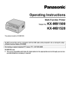
Matrix Power Company
MB xxx-3U series
Specification Document
TABLE OF CONTENTS
1. Scope
2. Applicable document:
3. Electric specification:
3.1 AC input requirement:
3.1.1 AC input requirement
3.1.2 Over current protection
3.1.3 Inrush current limiting
3.1.4 Input under voltage
3.1.5 Electrical fast transient/burst
3.2 DC output requirements:
3.2.1 DC voltage regulation
3.2.2 remote sense
3.3 power distribution:
3.3.1 Output requirement
3.3.2 Efficiency
3.3.3 Output ripple and noise
3.3.4 Output transient response
3.3.5 +5Vdc and +3.3Vdc power sequencing
3.3.6 voltage hold-up time
3.4 Timing / housekeeping / control
3.4.1 Power_OK
3.4.2 Power_ON
3.4.3 +5Vsb
3.4.4 Power ON time
3.4.5 Rise time
3.4.6 Overshoot at turn_on/turn_off
3.4.7 Reset after shutdown
3.4.8 +5vsb at power down
3.5 Output protection:
3.5.1 Over voltage protection
3.5.2 Short circuit protection
3.5.3 No load operation
3.5.4 Over current protection
3.5.5 Over load protection
3.5.6 Output bypass
2
4. Mechanical requirement:
4.1 Label and marking
4.2 Physical dimension
4.3 Air flow / fan
4.4 Connector
5. Environment requirement
5.1
5.2
5.3
5.4
5.5
5.6
Environment requirement
Thermal shook (shipping)
Humidity
Altitude
Mechanical shock
Vibration
6. Electromagnetic compatibility
7. Reliability
7.1 Mean time between failure (MTBF)
7.2 Compatibility
7.3 Safety requirement
3
1. SCOPE:
This document outlines the power supply specification of MB-3Useries.
2. Applicable Documents:
See ATX Specification Version 2.03/_12V version 2.3 and Intel ATX Power Supply Design
Guide EPS/SSI Version 2.91.
3. Electric specification:
The electrical requirements that follow are to be met over the environmental ranges specified in
Section 5 unless otherwise noted.
3.1 AC input requirement:
3.1.1 AC input requirement:
a.
The power supply shall be capable of supplying full rated output power over two
input voltages ranges rated 115Vac and 230Vac RMS nominal at 0℃ ~ 50℃.
b.
Input voltage range
Input frequency range
Selecting
85Vac ~ 135Vac
47Hz ~ 63Hz
Select switch
170Vac ~ 265Vac
47Hz ~ 63Hz
Select switch
c. Auto range:
**option.
d. PFC function
**optional
*For Active PFC Vin=100~240Vac full-range, PF=0.95min.
*For Passive PFC Vin=115/230Vac by-switch, PF=0.85 typ.
3.1.2 AC over current Protection:
The power supply shall incorporate primary fusing for input overcurrent protection. Fuses
should be slow-blow type or equivalent to prevent nuisance trips.
3.1.3 Inrush Current Limiting:
Maximum inrush current from power-on (with power on at any point on the AC Sine) and
including, but not limited to, three line cycles, shall be limited to a level below the surge
rating of the input line cord, AC switch if present, bridge rectifier, fuse, and EMI filter
components. Repetitive ON/OFF cycling of the AC input voltage should not damage the
power supply or cause the input fuse to blow.
3.1.4 Input under voltage:
The power supply shall contain protection circuitry such that the application of an input
voltage below the minimum specified in Section 3.1, Table 1, shall not cause damage to
the power supply.
3.1.5 Electrical fast transient/burst:
No unsafe operation is allowed under any condition. No user-noticeable performance
degradation up to +- 1 kV Mains, +- 500V Signal Cable, is allowed. Automatic or manual
recovery is allowed for other conditions.
4
3.2 DC Output Requirements
3.2.1 DC Voltage Regulation
The DC output voltages shall remain within the regulation ranges shown in Table 3 when
measured at the load end of the output connectors under all line, load, and environmental
conditions. The voltage regulation limits shall be maintained under continuous operation
for a period of time equal to or greater than the MTBF specified in Section 7.2 at any
steady state temperature and operating conditions specified in Section 5.
Output
+12Vdc
+5Vdc
+3.3Vdc
-5Vdc
-12Vdc
+5Vsb
Table 3: DC Output Voltage Regulation
Range
Min.
Nom.
Max.
±5%
+11.40
+12.00
+12.60
+5-4%
+4.80
+5.00
+5.25
+5-4%
+3.17
+3.30
+3.46
±5%
-4.75
-5.00
-5.25
±10%
-11.40
-12.00
-13.20
±5%
+4.75
+5.00
+5.25
Unit
Volts
Volts
Volts
Volts
Volts
Volts
3.2.2Remote Sensing
a. For the +12V, +5 V and +3.3 V, the power supply shall use remote sensing wires to
achieve regulation at the output connector to compensate for voltage drop of cable,
connector, and PCB trace. If the remote connection is lost to any of these outputs, then
internal resistive feedback causes the power supply to regulate and prevent OVP.
b. The power supply should have remote sense return (Returns) to regulate out ground drops
for all output voltages, +12V, +3.3V, and +5V. The power supply will uses remote sense
(+3.3Vs, +5Vs, +12Vs) to regulate out drops in the system for the +3.3V, and +5V
outputs. Remote sense must be able to regulate out a minimum of 250mV of drop on the
+3.3V and +5V outputs. The remote sense return (Returns) must be able to regulate out a
minimum of 100mV of drop in the power ground return. The current in any remote sense
line shall be less than 10mA to prevent voltage sensing errors. The power supply must
operate within specification over the full range of voltage drops from the power supply's
output connector to the remote sense points.
3.3 Power Distribution:
5
3.3.1 Output requirement:
Table 4.0: MB600-VA Power Distribution Configuration
Outputs
3.3V
5.0V
-5.0V
12.0V
-12.0V
5.0Vsb
MIN
0.0A
1.0A
0.0A
0.0A
0.0A
0.0A
MAX
25.0A
30.0A
0.5A
48.0A
0.8A
4.00A
Watt
Peak
82.5
30.0A
150.0
40.0A
2.5
1.0A
576.0
54.0A
9.6
1.5A
20.0
5.0A
Total = 600 Watt
Maximum combined wattage of 3.3V and 5.0V outputs is 150W.
Table 4.1: MB700-VA Power Distribution Configuration
Outputs
3.3V
5.0V
-5.0V
12.0V
-12.0V
5.0Vsb
MIN
0.0A
1.0A
0.0A
1.0A
0.0A
0.0A
MAX
25.0A
35.0A
0.5A
56.0A
0.8A
4.00A
Watt
Peak
82.5
35.0A
175.0
45.0A
2.5
1.0A
672.0
62.0A
9.6
1.5A
20.0
5.0A
Total = 700 Watt
Maximum combined wattage of 3.3V and 5.0V outputs is 175W.
Table 4.2: MB800-VA Power Distribution Configuration
Outputs
3.3V
5.0V
-5.0V
12.0V
-12.0V
5.0Vsb
MIN
0.0A
1.0A
0.0A
1.0A
0.0A
0.0A
MAX
25.0A
40.0A
0.5A
64.0A
0.8A
4.00A
Watt
82.5
200.0
2.5
768.0
9.6
20.0
Total = 800 Watt
Peak
40.0A
60.0A
1.0A
70.0A
1.5A
5.0A
Maximum combined wattage of 3.3V and 5.0V outputs is 200W.
Table 4.3: MB900-VA Power Distribution Configuration
6
Outputs
3.3V
5.0V
-5.0V
12.0V
-12.0V
5.0Vsb
MIN
0.0A
1.0A
0.0A
0.0A
0.0A
0.0A
Table 4.4:
Outputs
3.3V
5.0V
-5.0V
12.0V
-12.0V
5.0Vsb
MB1000-VA
MIN
0.0A
1.0A
0.0A
0.0A
0.0A
0.0A
Table 4.5:
Outputs
3.3V
5.0V
-5.0V
12.0V
-12.0V
5.0Vsb
MB1100-VA
MIN
0.0A
1.0A
0.0A
0.0A
0.0A
0.0A
Table 4.6:
Outputs
3.3V
5.0V
-5.0V
12.0V
-12.0V
5.0Vsb
MB1200-VA
MIN
0.0A
1.0A
0.0A
0.0A
0.0A
0.0A
MAX
25.0A
45.0A
0.5A
72.0A
0.8A
4.00A
Watt
Peak
82.5
40.0A
225.0
60.0A
2.5
1.0A
864.0
80.0A
9.6
1.5A
20.0
5.0A
Total = 900 Watt
Maximum combined wattage of 3.3V and 5.0V outputs is 225W.
Power Distribution Configuration
MAX
Watt
Peak
25.0A
82.5
40.0A
50.0A
250.0
80.0A
0.5A
2.5
1.0A
80.0A
960.0
88.0A
0.8A
9.6
1.5A
4.00A
20.0
6.0A
Total = 1000 Watt
Maximum combined wattage of 3.3V and 5.0V outputs is 250W.
Power Distribution Configuration
MAX
Watt
Peak
25.0A
82.5
40.0A
55.0A
275.0
80.0A
0.5A
2.5
1.0A
88.0A
1056.0
96.0A
0.8A
9.6
1.5A
4.00A
20.0
6.0A
Total = 1100 Watt
Maximum combined wattage of 3.3V and 5.0V outputs is 275W.
Power Distribution Configuration
MAX
Watt
Peak
25.0A
82.5
40.0A
60.0A
300.0
80.0A
0.5A
2.5
1.0A
96.0A
1152.0
105.0A
0.8A
9.6
2.0A
4.00A
20.0
6.0A
Total = 1200 Watt
Maximum combined wattage of 3.3V and 5.0V outputs is 300W.
Table 4.7: MB1500-VA Power Distribution Configuration
7
Outputs
3.3V
5.0V
-5.0V
12.0V
-12.0V
5.0Vsb
MIN
0.0A
1.0A
0.0A
0.0A
0.0A
0.0A
MAX
25.0A
75.0A
0.5A
120.0A
0.8A
4.00A
Watt
Peak
82.5
40.0A
375.0
100.0A
2.5
1.0A
1440.0
130.0A
9.6
2.0A
20.0
6.0A
Total = 1500 Watt
Maximum combined wattage of 3.3V and 5.0V outputs is 375W.
3.3.2 Efficiency
a. The efficiency of the power supply should be met over the AC input range defined
in Table 1, under the load conditions defined in Section 3.3, and under the
temperature and operating conditions defined in Section 5. The power supply should
be a typical of 72% efficient under full load as defined in the applicable
configuration.
b. The +5Vsb standby supply efficiency should be 65% at 2.0A output. Standby
efficiency is measured with the main outputs off and with PWR_ON high. The AC
input power shall not exceed 8 W when the main outputs are in the "DC disabled"
state with 1.0 A load on +5VSB and the input is 230Vac/50 Hz or 115Vac/60Hz.
3.3.3 Output Ripple/Noise
a. The following output ripple/noise requirements should be met throughout the load
ranges specified in Section 3.3, and under all input voltage conditions as specified in
Section 3.1.
b. Ripple and noise are defined as periodic or random signals over a frequency band of
10 Hz to 20 MHz. Measurements shall be made with an oscilloscope with 20 MHz
bandwidth. Outputs should be bypassed at the connector with a 0.1 uF ceramic disk
capacitor and a 47 uF electrolytic capacitor to simulate system loading.
Table 5: DC Output Noise/Ripple
Output
Max Ripple & Noise
(mVpp)
+12VDC
120
+5VDC
50
+3.3VDC
40
-5VDC
50
-12VDC
120
+5VSB
50
3.3.4 Output Transient Response
8
The +3.3VDC, +5VDC and +12V outputs will see transients up to 50% of the maximum
output current. \ The transient slew rate will be 2.5 A/ms. The power supply should be
stable under all transient conditions from any steady state load, and the over/undershoot
should be within the regulation band stated in Section 3.2.1.
3.3.5 +5VDC/+3.3VDC Power Sequencing
The +5VDC output level must be equal to or greater than the +3.3VDC output at all times
during power-up and normal operation. The time between the +5VDC output reaching its
minimum in-regulation level and +3.3VDC reaching its minimum in-regulation level
must be less than or equal to 20msec.
3.3.6 Voltage Hold-up Time
The power supply shall maintain output regulation per Section 3.2.1 despite a loss of
input power at the nominal range (Low = 115Vac, 60 Hz or 230Vac, 50 Hz) at
maximum continuous output load as applicable for a typical of 17 ms.
3.4 Timing / Housekeeping / Control
Figure 1: Power Supply Timing
Notes:
a. T2 is defined in Section 3.4.5
b. T3, T4, and T5 are defined in Table 7
3.4.1 PWR_OK
PWR_OK is a "power good" signal. It is asserted high by the power supply to indicate
that the +5VDC and +3.3VDC outputs are above the undervoltage thresholds listed in
Section 3.2.1 and that sufficient mains energy is stored by the converter to guarantee
continuous power operation within specification for at least the duration specified in
Section 3.3.6. Conversely, PWR_OK should be deasserted to a low state when either the
+5VDC or the +3.3VDC output voltages falls below the undervoltage threshold, or when
mains power has been removed for a time sufficiently long such that power supply
operation cannot be guaranteed beyond the hold-up time. The electrical and timing
characteristics of the PWR_OK signal are given in Table 7 and in Figure 1.
Table 7: PWR_OK Signal Characteristics
9
Signal Type
Logic level Low
Logic level high
High state output impedance
PWR_OK delay
PWR_OK rise time
Power down warning
+5 V TTL compatible
< 0.4 V while sinking 4mA
Between 2.4 VDC and 5 VDC
Output while sourcing 200uA
1KΩ from output to common
100 ms < T3 < 500 ms
T5 ≤ 10 ms
T4 > 1 ms
3.4.2 PWR_ON
a. PWR_ON is an active-low, TTL-compatible signal that allows a motherboard to
remotely control the power supply in conjunction with features such as soft on/off,
wake-on-LAN, or wake-on-modem. When PWR_ON is pulled to TTL low, the
power supply should turn on the five main DC output rails: +12VDC, +5VDC,
+3.3VDC, -5VDC, and -12VDC. When PWR_ON is pulled to TTL high or open
circuited, the DC output rails should not deliver current and should be held at zero
potential with respect to ground. PWR_ON has no effect on the +5VSB output,
which is always enabled whenever the AC power is present.
b. Power supply shall provide an internal pull-up to TTL high. The power supply shall
also provide debounce circuitry on PWR_ON to prevent it from oscillating on/off at
startup due to activation by a mechanical switch. The DC output enable circuitry
must be SELV-compliant.
3.4.3 +5VSB
+5VSB is a "standby" supply output that is active whenever the AC power is present. It
provides a power source for circuits that must remain operational when the five main DC
output rails are in a disabled state. Example uses include soft power control, wakeonLAN, wake-on-modem, intrusion detection, or suspend state activities. +5VSB is
required for the implementation of PWR_ON.
The +5VSB output should be capable of delivering 2.0A at +5 V ±5% to external circuits.
3.4.4 Power-on Time
The power-on time is defined as the time from when PWR_ON is pulled low to when the
+5VDC and +3.3VDC outputs are within the regulation ranges specified in Section 3.2.1.
The power-on time shall be less than 500ms. +5VSB shall have a power-on time of 2
seconds maximum after application of valid DC voltages.
3.4.5 Risetime
The output voltages shall rise from <10% of nominal to within the regulation ranges
specified in Section 3.2.1 within 0.1ms to 20ms (0.1ms < T2 ≤ 20ms).
10
3.4.6 Overshoot at Turn-on/Turn-off
The output voltage overshoot upon the application or removal of the input voltage, or the
assertion / deassertion of PWR_ON, under the conditions specified in Section 3.1, less
than 10% above the nominal voltage. There is a smooth and continuous ramp of each DC
output voltage from 10% to 90% of its final set point within the regulation band, while
loaded as specified in Section 3.3. The smooth turn-on requires that during the 10% to
90% portion of the rise time, the slope of the turn-on waveform is positive and have a
value of between 0 V/ms and [Vout, nominal] V / 0.1 ms. Also, for any 5 ms segment of
the 10% to 90% rise-time waveform, a straight line drawn between the end points of the
waveform segment must have a slope ≥ [Vout, nominal] V / 20 ms. No voltage of
opposite polarity present on any output during turn-on or turn-off.
3.4.7 Reset After Shutdown
If the power supply latches into a shutdown state due to fault condition on its outputs, the
power supply shall return to normal operation only after the fault has been removed and
the PWR_ON (or DC input) has been cycled OFF/ON with a minimum OFF time of 3
second.
3.4.8 +5VSB at AC Power Down
After AC power is removed, the +5VSB standby voltage output should remain at its
steady state value for the minimum holdup time specified in Section 3.3.6 until it begins
to decrease in voltage. The decrease shall be monotonic in nature, dropping to 0.0 V.
There shall be no other perturbations of this voltage at or following removal of AC power.
3.5 Output Protection
3.5.1 Over voltage Protection
The over voltage sense circuitry and reference shall reside in packages that are separate
and distinct from the regulator control circuitry and reference. No single point fault shall
be able to cause a sustained overvoltage condition on any or all outputs. The supply shall
provide latch-mode overvoltage protection as defined below.
Table 9: Overvoltage Protection
Output
Min.
Nom.
Max.
Unit
+12VDC
14.0
----15.0
Volts
+5VDC
5.8
----6.9
Volts
+3.3VDC
3.8
----4.3
Volts
3.5.2 Short Circuit Protection
An output short is defined as any output impedance of less than 0.1 ohms. The power
supply shall shut down and latch off for shorting the +3.3VDC, +5VDC, +12VDC, -12V
rails to return or any other rail. The power supply will shut down and latch off .
The +5VSB must be capable of being shorted indefinitely, but when the short is removed,
the power supply shall recover automatically .
The power supply shall be capable of withstanding a continuous short-circuit to the
output without damage or overstress to the unit (components, PCB traces, connectors, etc.)
under the input conditions specified in Section 3.1.
11
3.5.3 No Load Operation
The power supply shall be turn on, and no damage or hazardous condition should occur
with all the DC output connectors disconnected from the load.
3.5.4 Over current Protection: **OPTIONAL
If any one output of +5Vdc, +12Vdc and +3.3Vdc is over current then maximum load,
the power supply is shut down by over current protection design, the output voltage shall
drop to 0V at +5Vdc, +12Vdc, +3.3Vdc, +5Vsb, -5Vdc and –12Vdc output, and no any
damage to the power supply.
3.5.5 Over load protection:
The total power output is limit at 105~150%.
3.5.6 Output Bypass
The output return is connected to the power supply chassis. The return will be connected
to the system chassis by the system components.
4. Mechanical requirement:
4.1 Label and marking:
The label must be follow safety ( UL, cUL, TUV, CE ) request.
4.2 Physical dimensions:
The supply shall be enclosed and meet the physical outline listed .
** MB600~1200VA, 200*100*125mm, 3U, PWCS18/19/40, fan6020*4 .
** MB600~1500VA, 300*100*120mm, 3U, PWCS57, fan8020/38+6020/38 .
4.3 Airflow / Fan
Airflow will be provided by fans of 60/80/92mm in each power module and fans out
the computer chassis.
4.4 Cable:
following ATX/SSI/EPS specification.
5. Environment requirements:
5.1 Environment requirement:
Operating ambient temperature: 0℃~ 50℃
The power supply be capable of supplying full rated output power over two input voltages
ranges rated 115 Vac and 230Vac RMS nominal at 25℃.
Nonoperating ambient temperature: -40℃ ~ +70℃
(Maximum rate of change of 20°C/hr.)
12
5.2 Thermal shock (shipping):
Nonoperating:
-40 °C to +70 °C; 15 °C/min < dT/dt < 30 °C/min;
50 cycles; Duration of exposure to temperature extremes for each half cycle shall be 30
minutes.
5.3 Humidity:
Operating: To 85% relative humidity (noncondensing)
Nonoperating: To 95% relative humidity (noncondensing)
Note: 95% RH is achieved with a dry bulb temperature of 55 °C and a wet bulb temperature
of 54 °C.
5.4 Altitude:
Operating: To 10,000 ft
Nonoperating : To 50,000ft
5.5 Mechanical Shock
Nonoperating :
50 g, trapezoidal input; velocity change > 170 in/s. Three drops on each of six faces are
applied to each sample.
Operational:
The unit will be able to withstand 10g acceleration peak (11msec pulse duration).
5.6 Vibration
Nonoperating :
0.01 g2 / Hz at 5Hz, sloping to 0.02 g2/Hz at 20Hz, and maintaining 0.02 g2 / Hz from 20
Hz to 500 Hz. The area under the PSD curve is 3.13 gRMS. The duration shall be 10
minutes per axis for all three axes on all samples. Also meet 5 - 17Hz, 0.1” double
amplitude displacement; 17-500Hz, 1.5G acceleration; 5 to 500Hz random, 1G(RMS)
acceleration.
6 . Electromagnetic Comp atibility ( EMC )
Meet CE .
Meet FCC .
Meet CNS13438 .
13
7 . Reliability
7.1 Mean time between failu re (MTBF):
MTBF shall be follow 570F standard.
a. Full load.
b. 230Vac input.
c. Ground benign.
d. Ambient temperature: 25℃
The calculated MTBF of the power supply shall be greater than 100,000 hours under the
following conditions:
a. Full load.
b. 230Vac input
c. Ground benign
d. 25°C ambient.
7.2 Compatibility
All versions of the power supply will be backward compatible for form, fit, and function of
the ATX/0.9/1.0/1.1/2.01/2.02/2.03/_12V/1.0/1.1/1.2/1.3/2.0/2.3/_SSI_2.91 Version.
7.3 Safety & EMC Requirements
The power supply must be meet UL, c-UL, TUV, CE, FCC, CB, CNS .
7.4 Web side:mapc.com.tw
14