1
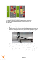
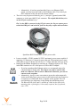
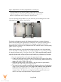
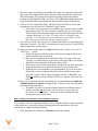
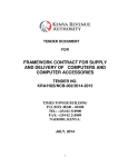
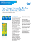
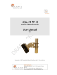
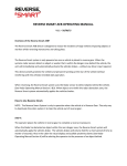
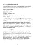
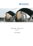
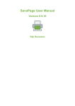
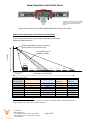
Radar SpeedLane Quick Start Guide Version 1.2 Dated January 20th 2015 Transparent enclosure shown for illustrative purposes only. Actual product has opaque white enclosure and natural anodized brackets. SpeedLane Non-Intrusive Dual FMCW Radar Based Traffic Sensor and Collector STEP1: Select appropriate location and mounting height Pick a mounting location where you are able to best satisfy the following height and setback guidelines. Radar pointed down between one-third and one-half of the detection zone Height Acceptable range of pointing variation. Ln 1 Ln 2 Setback Ln 3 Ln 4 Ln 5 Ln 6 Ln 7 Ln 8 Maximum 145 feet (44m) SpeedLane Setup Table Number of 12 Minimum Setback (ft) feet (4m) lanes1 1 6 2 10 3 13 4 15 5 17 6 20 7 22 8 24 Minimum Setback (m) 1.8 3.0 4.0 4.6 5.2 6.1 6.7 7.3 1 Minimum Height (ft) 4 17 17 20 21 23 25 27 Minimum Height (m) 1.2 5.2 5.2 6.1 6.4 7.0 7.6 8.2 Lanes may be narrower than shown. 12 feet (4m) is used as an example. Setback and height are based on range to furthermost vehicles, not actual lane numbers. www.dytrone.com Email: [email protected] USA: PO Box 19882, Denver, CO 80219; (209) 604-0039 AFRICA: Haile Selassie Ave., PO Box 74165, Nairobi, Kenya +1 254 720 829302 Page 1 of 9 The SpeedLane can support a maximum of 8 lanes, with each lane moving in any direction. The far edge of the farthest lane should be no more than 145 feet (44m) away. STEP2: Prepare to install the SpeedLane™ Ensure you have 0.5” (12mm) wide steel banding straps to attach the SpeedLane to the pole. Locate the provided 3/16” Allen key to loosen the clamp brackets enough so that the tube can be easily rotated by hand. This will allow you to make pitch adjustments to align the up/down pointing of the radar as recommended in the mounting chart in Step 1 above. The SpeedLane has an onboard sighting video camera that will be used for alignment purposes. You must prepare to power up the SpeedLane during installation and connect to it from our StatsAnalyzer software running on a Windows PC. o If you are planning to power the device via 12VDC, locate the 5 pin M12 cable shown below and connect it to the connector on the right side of the radar (side away from camera window). Hand tighten completely. Page 2 of 9 o Alternatively, if you have purchased the Power over Ethernet (PoE) option, you may power the radar via the Ethernet cable. This is the 4 pin M12 connector on the side near the camera window. The device may be powered either by pin 1 (+) and pin 5 (ground) on the DB9 connector or via the provided DC jack connector. The striped (black/white) wire on the DC jack connector is (+). Pin 1 on the DB9 is connected to the DC jack center pin. Do not connect power to both the DB9 pin 1 and to the DC jack else they may conflict with each other. SpeedLane RS232 Serial and +12VDC power cable. Locate a suitable +12VDC nominal (15VDC maximum) power source capable of supplying 2.5 Watts (or 0.21 Amps) to power the unit. The nominal power usage of the radar is only 0.8 Watts, but will rise to 2.1 Watts when the camera is in use. Install provided Radar StatsAnalyzer software on a Windows laptop or PC. Plug in the DB9 connector to a PC serial port or a USB to RS232 adapter. o If you have purchased the Ethernet option, we recommend using it for communication with the radar. The camera can only be used in video mode over Ethernet. With a serial or Bluetooth connection, you can use camera to take snapshots. o Alternatively, it may be more convenient to power the radar temporarily via the serial cable from a power source in the bucket truck, but connect to it wirelessly over Bluetooth from a computer on the ground. This will avoid having to use temporary wiring during the installation process. The Bluetooth ID of the radar is printed on a label on the back of the mounting plate. A pairing key is not usually required, but if requested, enter 1234. Page 3 of 9 STEP3: Power ON and verify proper connection while still on the ground Power on the radar and wait about 45 seconds to allow it to finish booting. Then start up the Radar StatsAnalyzer (or the Radar Configuration tool) software and click on File->Connect to Radar… If you have decided to connect via a local serial port or Bluetooth, select “Auto Detect Port” or the port number for the serial port or Bluetooth connection and then click on “Connect”. If you are connecting via Bluetooth, you must have already paired the computer to the SpeedLane’s Bluetooth and had a COM port assigned before starting the Radar program. You can do this via “Add New Connection” by right clicking on the Bluetooth manager icon in your Windows status bar. This procedure is required only once per computer/SpeedLane connection. If you have decided to connect via Avahi/Bonjour™ using Ethernet, pull down the “Connect To Radar On” list and select the “Local Network” option. You must have installed the Apple Safari browser on your Windows PC with the Bonjour™ option for this feature to work otherwise there will not be a “Local Network” option. See the user manual section titled “Connecting to the SpeedLane over Ethernet” for more details. Once the radar is found: 1. Check the clock and ensure it is correct. It is set to US Central Time from the factory. Make sure your PC clock is accurate and then click the “Sync Radar Clock to Computer” button to set the radar clock. 2. Click over to the “SpeedLane Setup” tab and set the correct units (mph or km/h) for your region. 3. Set a reasonable “Clutter Time Constant” value for the type of traffic you are expecting. A typical value of 15 to 20 minutes is reasonable for most highways. Refer to the user manual for more details. 4. Click over to the “Advanced” tab and ensure the “Multipath reflections” settings are unchecked at this time. 5. Click the “Save Changes” button to save the changes to the SpeedLane. You are now ready to strap the SpeedLane to the pole and complete setup. At this point power down the radar and proceed to the next step. Page 4 of 9 Step 4: Adjustments and setup of SpeedLane™ on the pole The SpeedLane has an onboard sighting camera that can be used for alignment purposes. Utilizing this camera during the setup process makes it significantly easier to properly align the radar. If you are mounting the SpeedLane to a pole, attach the pole mounting bracket to the mounting plate of the radar as shown below: The bracket is designed to provide roll adjustment (clockwise or counter clockwise rotation when looking at the SpeedLane) to compensate for a sideways leaning pole. If this is required, loosen the bolts slightly before strapping to the pole to allow roll adjustment while viewing the video/snapshots from the on-board camera. After adjusting, tighten all bolts completely. Follow the steps below to get the SpeedLane aligned so that the view of the road looks correct and traffic is reliably detected. You can take snapshots or view video by clicking the appropriate button on the “SpeedLane Setup” tab. A little extra effort at this stage to properly align the radar will pay off in terms of trouble free performance of the radar. 1. Loosely strap SpeedLane to the pole at the appropriate height. 2. Connect the cables and power on the radar. Secure the service loops of the cables via strain relief clamps provided on the bracket. Do not rely on the connectors to support the entire weight of the cable. 3. Rotate the SpeedLane tube in the clamps so that the camera is approximately pointed to the middle of the lanes being detected. 4. Now turn the entire assembly around the pole (perhaps with some roll adjustment using the pole mounting bracket) till the edge of the roadway shows parallel to the bottom of the photo/video frame. This is an important step. See the two examples below. The objective is to align the SpeedLane parallel to the road surface, road edge and perpendicular to the passing traffic. Page 5 of 9 Incorrect alignment. Yellow line of road edge is slanting at an angle to the bottom of the picture. Entire assembly should be rotated left on pole to make it parallel with the road edge. Correct Alignment. Edge of road is parallel to the radar and picture bottom edge. 5. Once the SpeedLane tube is aligned to the edge of the road, tighten the banding straps to the pole and the 4 bolts of the pole mounting bracket. 6. Next adjust the pitch of the tube so that the camera is pointed such that the center of the lanes being detected is in the middle of the photo frame. See example below: Incorrect pointing of the radar. There are 3 lanes on the far side not visible at all. Rotate tube up in clamps to make median between the two directions show up in the middle of the picture. Stripe on road edge is also slanting right which is incorrect. Page 6 of 9 Correct pointing of the radar. Median between the two directions shows up in the middle of the picture frame and road stripe is level with photo bottom edge. 7. Once the camera is pointing to the middle of the lanes to be detected, tighten all 4 bolts in the tube clamps till the split washers are fully compressed to prevent the tube from rotating. The clamps are designed to tightly grip the tube without crushing it when tightened all the way down. Also tighten the banding straps and any pole bracket bolts to prevent the unit from moving in high winds and rain. 8. Click over to the “SpeedLane Setup” tab and wait for the traffic to clear on the road (the best you can) and click “Initialize Clutter” button. If the road is very busy and you are unable to get a window with no traffic, temporarily set the CTC time constant to a small value (e.g. 10 seconds). This will allow the background clutter to be automatically cleared in about a minute. Remember to set the CTC value back to a reasonable value (typically 15 to 20 minutes) for your road before you are done else you may not get proper detections during congested traffic. 9. Now click over to the “SpeedLane Plot” window and ensure you are getting good detections. Check the “Show RSS” box and ensure you get at least 3 or more filled signal strength bars on most targets. 10. Setup your lanes on the range plot (right click and select “Define New Lane” or “Edit Lanes…” option. Define one lane for each lane on the road. Do you attempt to define one lane for multiple lanes on the road. Do not leave a gap between defined lanes if there is no gap on the road. Typically you would only have gap between the lanes if there is a median, shoulder or some other part of the road with no traffic. Do not try to overlap lanes (the software will prevent you from doing this). Setup the lane direction to match the direction of travel on the road. Defining lanes is not mandatory, but recommended. If you do not wish to define lanes, interval summary data will not be recorded and you must query the “targets” table to query the logged vehicles. Additionally, you must not enable any of the “Multipath Rejection” options in the next step below. 11. Once you are satisfied with the lane settings we recommend that you enable the “Multipath Rejection Options” settings in the “Advanced” tab. This will ensure the best possible performance. Exception: if you have a lane that changes direction at different times of the day, you must not check the “Reject vehicles moving in opposite direction from lane definition”, else traffic will not be detected when moving in the opposite direction. Step 5: Setup your external router/modem if required If you wish to access the SpeedLane remotely via an external modem or router connected to the SpeedLane, you need to forward incoming network connections to allow the remote host to connect into the SpeedLane. 1. If the SpeedLane is connected via Ethernet to the router/modem: Page 7 of 9 Assign an unused private static IP address to the SpeedLane via the SpeedLane Setup->Ethernet tab. On the modem, select any available external port number you wish to use (e.g. 5000). In the modem configuration forward all TCP/IP traffic for this external port number to the SpeedLane IP address at port 23. If you wish to use the video streaming feature, you also need to forward all TCP/IP traffic for external port 8080 to the SpeedLane IP address at port 8080. 2. If the SpeedLane is connected via serial port: On the modem, select any available external port number you wish to use (e.g. 5000). In the modem configuration forward all TCP/IP traffic for this external port number to the local serial port on the modem connected to the SpeedLane. o Ensure you do not have any “terminal editing” settings enabled on this serial port and you are using it in “raw” mode without any character translation. Setup the modem serial port with the following parameters o 115200 baud, 8 data bits, 1 stop bit, no parity and no handshaking. 3. On the remote host computer, setup a “Remote Radar Connection” in the Radar Stats Analyzer program via “File-Setup Remote Radar Connection…”. Use the external well known public IP address or hostname of the modem and the external port number you selected in the steps above (5000 in example above). 4. Ensure you can make a connection from the remote computer to the SpeedLane and can view video if you have connected via Ethernet and forwarded the video streaming port 8080. Page 8 of 9 This device complies with part 15 of the FCC Rules. Operation is subject to the following two conditions: (1) this device may not cause harmful interference, and (2) this device must accept any interference received, including interference that may cause undesired operation. The device must be located 20 cm or more from persons. The device must not be co-located with other transmitters. Changes or modifications not expressly approved by the party responsible for compliance could void the user's authority to operate the equipment. Any modification or use other than specified in this manual will strictly void the certification to operate the device. Product contains no user serviceable parts inside. Do not attempt to open or repair. Doing so will void all warranty. Specifications may change without notice. Page 9 of 9