1
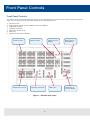
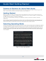
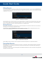
Solution Series
Quick Start Guide
English 1.0
Introduction
This Manual
This manual describes the operation of the Solution and Solution XL lighting desks.
This chapter contains an overview of the capabilities and controls of the Solution & Solution XL.
The Quick Start Guide is designed to get you up and running with the desk, but is not a substitute for the complete
Manual. For more detail on each function, please consult the full user manual.
Conventions
Throughout this manual the following conventions are used:
References to front panel controls, buttons and lights appear in capital letters, for example:
GRAND MASTER, COLOUR, FIXTURES.
Multi Function Keys (MFKs) and soft buttons which appear on the monitor screens are displayed as follows:
[Patch], [Desk Setup], [Files], [Clear Options].
The Solution & Solution XL Lighting Desk
A summary of the main functions of the Solution & Solution XL lighting desk is as follows:
Control Channels
The Solution & Solution XL desk have 2048 channels of control as standard. These can be assigned and patched
to dimmers and fixtures. The actual configuration is dependent on the desk type.
Dimmers
The Solution desk has 48 faders which control 24 dimmers (two preset mode) or 48 dimmers (wide mode).
The Solution XL desk has 96 faders which control 48 dimmers (two preset mode) or 96 dimmers (wide mode).
1
Introduction
Fixtures
The Solution & Solution XL desks can control up to 200 fixtures. Fixtures can be a simple generic lamp or colour scroller,
a moving mirror or moving head (eg Goldenscan, MAC 250), or any other item controllable via a standard DMX signal.
Moving heads, moving mirrors, LED and video systems controlled by DMX are fixtures with multiple parameters. Within
the Fixture Library, the Solution & Solution XL is told which channels control which parameters of the fixture. These are
then grouped into Position, Colour and Beamshape.
Fixtures can be given a user defined name and number, for ease of reference and may be patched to any of the DMX
output channels (1 – 512) on any of the DMX universes (1 – 4).
Fixture parameters can be manipulated from within the Program Window, from where they can be added to memories,
submasters, palettes or macros.
Dimmers are essentially a one channel fixture and as such further dimmers can be patched as fixtures if required.
Memories
The desk allows you to record memories, for use in the Memory Stack (Playback X). Each memory has a number, name
(optional), trigger, a wait time (auto cues) and a set of delay, and fade times. Memories may be a Scene or a Chase.
•
•
Scene – A single set of dimmer and fixture parameter data
Chase – A number of steps, each containing a set of dimmer and fixture parameter data, plus modifiers which
determine how the chase runs when played back
Submasters
Submasters may be programmed directly with a scene or a chase or they may contain a transferred memory.
•
•
The Solution desk has 20 pages of 10 submasters
The Solution XL desk has 20 pages of 30 submasters
Groups
The desk provides 400 user definable groups. Automatic groups for each fixture type in the schedule can be generated
from the Setup area, if required.
Palettes
The desk provides 400 user programmable palettes for each of the attributes (Colour, Beamshape and Position). The desk
can also generate auto palettes which provide basic colours, gobos and positions based on the fixture types used in the
desk.
Effects
The desk provides 400 user programmable effects. The desk can also generate a number of standard effects which
include intensity, colour, beamshape and movement effects.
Macros
The desk provides 400 user programmable macros.
Operating Mode
The desk has a three seperate operating modes which can be selected for various operators of different skill levels.
2
SMPTE/MIDI/CAN
The desk provides SMPTE, MIDI and CAN connections as an optional upgrade card, which can be used to trigger memories
with SMPTE or MIDI timecode triggers, or via ChilliNet.
Ethernet
The desk has an Ethernet port capable of outputting DMX over Art-Net or sACN. In addition to Ethernet DMX outputs,
this allows handheld devices to be used as remotes.
USB Ports
The desk has four USB ports, which may be used for saving and loading show files, loading user fixture types and
performing software upgrades. The USB ports on the desk support keyboard, mouse, external touch screens, memory
sticks, USB CDRW drives, USB floppy disk drives and desk lights.
Mouse and External Keyboard
The desk provides a USB mouse interface to allow you to move quickly around the monitor screen, select fields, choose
options etc.
The desk provides a USB interface to a standard PC keyboard, to allow text and numeric data to be entered.
Video Output
The desk provides the interface for one external monitor display (XGA). It is highly recommended that the desk is operated
with a monitor display connected, as important information is displayed here.
DMX Output
Data is output on DMX channels 1 – 512 on four DMX universes as standard. The DMX output sockets on the rear panel of
the desk default to outputting universes 1 to 4. Universes 1 to 4 can also be output via Ethernet using either Art-Net or sACN,
see the chapter on Ethernet Options in the full user manual for further details.
3
Front Panel Controls
Front Panel Controls
This section of the manual describes the various controls and displays on the front panel of the Solution & Solution XL
desk. The front panel controls have been divided into the following sections:
•
•
•
•
•
•
•
Preset Controls
Page Controls, Mode Keys and Multi Function Keys (MFKs)
Submaster Controls
Playback X Controls
Other Keys and Controls
Main LCD
Wheel LCD and Control Wheels
Preset Controls
Submaster Controls
Page Control &
Display
Master Faders
Playback X Controls
Main LCD
Figure 1 - Solution desk layout
4
Multi Function
Keys (MFKs)
Wheel LCD &
Control Wheels
Preset Controls
Preset Faders
The Solution desk has 48 preset faders arranged as two rows of 24 faders and buttons. These control 24 dimmer channels
in two preset mode or 48 dimmer channels in Wide mode.
The Solution XL desk has 96 preset faders arranged as two rows of 48 faders and buttons. These control 48 dimmer
channels in two preset mode or 96 dimmer channels in Wide mode.
Figure 2 - Preset Controls
Channel Flash Buttons
The Solution desk has 48 flash buttons located below the PRESET faders.
The Solution XL desk has 96 flash buttons located below the PRESET faders.
The CHANNEL FLASH buttons are used to flash, solo or latch the dimmer channels or to select the channels or fixtures
assigned to the corresponding faders; their action being determined by the setting of the FLASH MODE button in Special
Page 1 of the MFKs.
A and B Master Faders
Two Preset Operation – The A MASTER fader controls the maximum output levels from the PRESET A FADERS.
The B MASTER fader controls the maximum output levels from the PRESET B FADERS.
Wide Operation – The A MASTER and B MASTER faders control the maximum output levels from all the PRESET faders
or the stored scene according to the setting on the PRESET CONTROL button.
Preset Control Button
The PRESET CONTROL button is only applicable in Wide Mode and is used to control which of the A or B MASTER faders
has control of the preset faders and which has control over the stored scene. The red LEDs in the button indicate the
current state. Pressing the button swaps the function of the two faders.
5
Page Controls, Mode Keys
Page Controls, Mode Keys and Multi Function Keys (MFKs)
This section of the front panel contains page controls and a seven segment display, a set of Mode keys (FIXTURE, GROUP,
COLOUR, BEAMSHAPE, POSITION, EFFECTS, MACRO, SPECIAL) and a block of 20 Multi Function Keys (MFKs).
Page Controls and Display
The current Page (1-10) is indicated on the dual seven segment display.
The PAGE UP and PAGE DOWN keys are used to select the required page.
Pressing the PAGE UP and PAGE DOWN keys together selects Page 1.
Each mode (Fixture, Group, Colour etc.) has its own current page.
Mode Keys
The mode keys (FIXTURE, GROUP, COLOUR, BEAMSHAPE, POSITION,
EFFECTS, MACRO, SPECIAL) determine the function of the block of
20 Multi Function Keys (MFKs).
Each of the mode keys contains a red LED, which is lit when selected.
If the mode key is flashing, this indicates that the wheels are in control
of this attribute but the MFKs are showing another function. This allows
simultaneous selection of fixtures whilst still manipulating attributes,
for example.
The function of the Mode keys is summarised below:
FIXTURE
– turns the block of 20 MFK’s into Fixture selection buttons.
GROUP
– turns the block of 20 MFK’s into Group selection buttons.
COLOUR
– turns the block of 20 MFK’s into Colour Palette selection buttons.
BEAMSHAPE – turns the block of 20 MFK’s into Beamshape Palette selection buttons.
POSITION
– turns the block of 20 MFK’s into Position Palette selection buttons.
EFFECTS
– turns the block of 20 MFK’s into Effect Palette selection buttons.
MACRO
– turns the block of 20 MFK’s into Macro selection buttons.
SPECIAL
– turns the block of 20 MFK’s into Special function keys.
6
Figure 3 - Solution
desk layout
Multifunction Keys (MFKs)
Multi Function Keys (MFKs)
The Multi Function Keys are arranged in 4 rows of 5 keys with a graphical LCD above each row of keys. The brightness
and contrast of the LCDs can be adjusted as required.
Each Multi Function Key contains a red LED. These LEDs are used to indicate which fixtures, groups etc. are selected
depending on their current function.
Pressing and releasing one of the Mode Keys changes the MFK’s to that page and the control wheels follow (when
appropriate). The MFKs remain in that mode until a different Mode key is pressed.
Pressing and holding down a Mode key temporarily changes all the MFKs to that function. Selecting an MFK will apply
that MFK but the MFKs will return to the previous MFK mode, when the Mode key is released.
For example – Press and release the FIXTURES key. The MFKs change to fixture selection keys. Select a number of
fixtures. Press and hold down the COLOUR key. The MFKs change to colour palette selection keys (while the COLOUR
key is being held down). Press one of the colour palette MFKs to apply the colour palette to the selected fixtures.
Release the COLOUR key and the MFKs return to being fixture selection keys.
Multi Function Key LCDs
The LCDs above the MFKs typically display three lines of data.
Example 1 (Figure 4) - When the MFKs are assigned to colour palettes - The first line shows the number of the palette
and the data stored. The second (and third if required) lines show the palette name.
Figure 4 - MFK's assigned to Colour Palettes
Figure 5 - MFK's assigned to Fixtures
Example 2 (Figure 5) - When the MFKs are assigned to fixtures – The top line shows the fixture number. The second
and third lines show the fixture name, eg MAC 250.
7
Submaster Controls
Figure 6 - Submaster Controls
Submaster Faders
The Submaster faders are used to output channel data (scenes) or chases. The fader controls the output level of the
intensity channels and triggers the LTP channels in the programmed data.
Submaster Flash Buttons
The Submaster flash buttons, located below each of the submaster faders are used to flash, solo or latch the data
programmed on the submaster. The action of these buttons is user definable via the Submaster Setup Window.
These buttons are also used to select submasters when in the Submaster Window.
Submaster Page Controls and Display
The current Submaster Page (1-20) is indicated on the dual seven segment display.
The PAGE UP and PAGE DOWN keys are used to select the required submaster page.
Pressing the PAGE UP and PAGE DOWN keys together selects submaster Page 1.
Submaster Step Button
The Submaster STEP button is used to manually step through any chases with manual drive being output on the
submasters, or to initiate Beat tempo matching.
8
Playback Controls
Figure 7 - Playback X Controls
Playback X (Memory) Master Fader
The MASTER fader controls the maximum output level of the memory being output on the Playback X. This fader only
affects the dimmer and brightness fixture channels (if applicable). The Colour, Beamshape and Position fixture channels
are not affected by the master fader.
Go Button
The GO button is used to initiate a crossfade between the memory currently being output and the Next memory in the
memory stack as indicated on the Memories screen.
Pause Button
The PAUSE button is used to pause a crossfade between the current and next memories. When a crossfade has been
paused, the red light in the button flashes. Pressing the GO button releases the pause. Pressing Pause again will step
backwards in the cue stack.
Override Control
The OVERRIDE control is used to slow down or speed up the crossfade between the current and next memory. When
the control is moved away from the central neutral position, this is indicated on the monitor screen.
Step Button
The STEP button is used to manually step through any chase memory with manual drive currently being output on the
Playback X.
9
Other Keys and Controls
Figure 8 - Other Keys & Controls
SETUP - used to enter Setup mode and display the Setup screen on the Main LCD and monitor. Also used for exiting
Setup mode.
MEMORIES - used to display the Memories screen on the Main LCD and monitor.
SUBMASTERS - used to display the Submasters screen on the Main LCD and monitor.
OUTPUTS - used to display the Outputs screen on the monitor.
PGM WIN - used to display the Program Window (programmer) on the monitor.
Cursor Keys (UP, DOWN LEFT, RIGHT) - used to move around the fields on the main LCD (where appropriate) and/or
the monitor screen. These buttons are equivalent to the four cursor keys on an external keyboard (if fitted).
Plus (+) and Minus (-) - used to increment or decrement the value of the current selection.
NAME - used for naming memories, submasters, palettes etc.
TIME - used as a shortcut for moving the cursor to the various fade fields on the Memories and Submasters screens.
It is also used incombination with other keys to perform various functions over the internal fade time (eg outputting
palettes over a time).
LOAD - used for loading items such as memories, submasters or palettes into the Program Window for editing.
CLEAR - used for clearing the Program Window. As soon as any changes are made to the look in the Program Window,
the LED in the CLEAR key is lit, to indicate that dimmer or fixture parameter values have changed. Pressing the CLEAR
key once will clear (undo) all the operations made in the Program Window since the LED was first lit, except for the fixture
selection. The LED in the key goes out. Pressing the CLEAR key a second time clears the fixture selection in the Program
Window.
UPDATE - used to update loaded items or items modified in the Program Window. 10
Figure 9 - Multi Function Faders
RECORD - used for programming memories and submasters.
COPY - used to copy items from one location to another (eg memories, submasters, groups, palettes etc.) Holding
down SHIFT and pressing COPY is used to transfer a memory onto a submaster.
INSERT - used to insert point memories, add or insert chase steps or add or insert duplicates when patching dimmers
and fixtures.
DELETE - used when deleting items (memories, submasters, groups, palettes etc.)
ENTER - used for completing commands and selecting ‘soft’ buttons on the Main LCD, monitor screens and popup
windows.
HOME - used as a quick method for setting all the parameters, or all the parameters for a particular attribute to their
home values. The Home values are found in the Edit Fixtures table in Setup and can be adjusted as required.
GRAND MASTER - controls the final output values of all dimmer and fixture intensity channels, resulting from the
Program Window, Playback X and submasters. The Grand Master level is displayed on the monitor screen.
BLACKOUT - reduces the outputs of all dimmer and fixture intensity channels to zero. Pressing the BLACKOUT key
toggles between active and not active. The red LED in the BLACKOUT key flashes when blackout is active.
SHIFT - used in conjunction with various front panel controls to provide additional functions, eg holding SHIFT and
pressing the COLOUR key displays the Colour Palette Window on the monitor.
11
Main LCD & Wheel LCD
The Main LCD provides part of the user interface on the front panel of the desk. The content, layout, operation and
other information displayed on this screen is dependent on the current operation being carried out on the desk.
In Setup, the Main LCD acts as a guide showing where you are in the Setup menu structure and gives instructions
on what to do.
When the Memories or Submasters screen are selected, the Main LCD acts as a small viewing portal on the Memories
or Submasters window.
When any of the other main windows (Program Window, Outputs, Groups etc.) are selected, the Main LCD displays a
simple text message directing you to refer to the monitor, plus the desk software version and other helpful information,
for example:
Figure 10 - Main LCD
Figure 11 - Wheel LCD
Wheel LCD
The Wheel LCD is used to indicate which fixture parameters or other data are being controlled by each of the three
control wheels.
Example - When showing fixture parameter values - The Wheel LCD displays the parameter name (eg Colour1) and
the value in %, DMX or the parameter detail name.
Tag status is shown by inverse graphics – an inverted display shows a tagged parameter, and a true colour display
shows an untagged parameter.
Control Wheels
The three control wheels are used for setting fixture parameter levels and other data. The names of the fixture
parameters or other data currently assigned to each of the wheels and their values is shown on the Wheel LCD.
Wheel Editing Modes
There are a number of wheel editing modes which apply when editing several fixtures at the same time (Absolute,
Relative, Fan First, Fan Middle, Fan Last, Fan V).
For each attribute there is a normal wheel mode which applies when the control wheel is moved and a shifted wheel
mode which applies when the SHIFT key is held down and the control wheel is moved.
For further details on each of the wheel editing modes, and how to adjust the normal and shifted mode for each
attribute – see page 82 of the full user manual for full details.
12
Quick
Start Getting
Started
Front Panel
Controls
Solution & Solution XL Quick Start Guide
Welcome to the Solution & Solution XL Quick Start Guide. This chapter is intended to get you started using your new
desk – for full information, please see the relevant chapters of this User Manual.
Getting Started
Before you power up the desk, it is essential to attach all the peripherals you will be using. The desk has support for
USB peripherals such as a Keyboard and Mouse and a VGA monitor (or touch screen). In addition, you should connect
the DMX or Ethernet cables for controlling your lighting rig.
These must be connected before powering up, as subsequent connection could result in software or hardware
malfunctions.
Once you have connected all the peripherals you require, power on the desk using the switch on the rear panel. If you
see no immediate response, check that the power switch is set to ON, and that the IEC lead is firmly attached to the
external power supply. The desk will boot up and you will be presented with the desk software.
Selecting Operating Mode
There are three operating modes for the Solution & Solution XL desks. These operating modes are designed for operators
with different skill levels to ensure they get the maximum out of the console. For the purposes of this Quick Start Guide,
we will select Non Tracking Mode. In this mode, everything that is output from the desk is recorded into each cue, and
changes made in one cue will not affect other cues. As you progress your knowledge of the Solution & Solution XL you
may want to experiment with the other modes. Details of these modes can be found in the full user manual, see page
75 for full details.
Figure 12 - Select Operating Mode
13
Quick
Guide
GrandStart
Master
and Blackout
Controlling Dimmers
The default setup for the desk gives you control of dimmers 1 to 48 (DMX addresses 1 to 48 on Universe 1) on the
generic preset faders 1 to 48 (1 to 96 on the Solution XL).
This can be defined differently, but for now we will assume you’re working with the default settings. Check that the
GRAND MASTER fader is at the top (100%) and that the A and B MASTER faders are also at the top. The LED in the
PRESET CONTROL button should be lit in “A Faders B Stored”, indicating that the A MASTER is controlling the level
of the Preset Faders. Moving the Preset Faders will bring their channels on, and you will see the result on stage.
You will also see the results in the Program Window (see later in this guide). You can bring the A MASTER fader down
at any time to inhibit the level of the Preset faders.
Programming
Once you have set up a scene that you like you can then record that state into a memory, or a submaster. Memories
are played back sequentially in a theatre style (Cue 1 GO, Cue 2 GO, etc). Submasters are mixed together by raising
the faders, useful for live events or unpredictable shows.
Memories
Recording a Memory
If you aren’t already in the Memories Window, press the MEMORIES key. This will bring the Memories Window up
onto the monitor, and Memory 1* will be highlighted as the “Next” memory. As a rule any changes you are making on
the monitor or LCD will happen to the highlighted “Next” memory, so follow the yellow bar on the monitor – the green
bar simply shows the current memory.
Now select the memory number to be programmed, if different to the one already selected. This can be done using
the + and – keys, or by pressing ENTER then using the MFKs to enter a numeric value.
To store the memory, simply press the RECORD key. The 1* will change to a 1 (the * indicates that the memory is
unprogrammed) and fade times will appear for the parameters you have recorded.
The Next memory automatically increases to select another memory.
Subsequent memories can then be set up and recorded using the same method.
Adjusting Fade and Delay Times
By default, a memory will receive a 3 second fade time on the intensity parameters (dimmers) and a 0 second fade time
on all moving light attributes (colour wheels, gobo wheels, etc). These are displayed in the Memories Window in the
relevant columns. Note that only one of Colour, Beamshape and Position times are shown at any one time – press the
relevant key to switch the monitor to displaying these times.
The fade and delay times can be adjusted by moving the cursor to the required field in the Memories Window and using
the control wheels, or by moving to the field on the Memories Window, pressing the ENTER key, typing in the time using
the MFKs and pressing ENTER to confirm. See the Memories chapter in the User Manual for full details of adjusting
times.
14
Quick Start Guide
Editing Memories
You can make changes to a memory by loading it back into the Program Window. To do this, press the MEMORIES key
to display the Memories Window. Select the memory to be edited, then press the LOAD key. The Load Options Window
is displayed on the monitor:
Figure 13 - Load Memories Window
Select the [OK] button to load the memory into the Program Window. The levels from this memory will be output. Now
you can make changes using the preset faders and fixture controls, and press the UPDATE key. The Update Options
Window is displayed on the monitor. Select the [OK] button to complete the edit.
Naming Memories
Each memory can have a name associated with it. These are displayed in the memories window and can be useful for
reminding you of the contents of a particular memory.
To set the name, press the MEMORIES key to display the Memories Window. Select a programmed memory to be
named. Press the NAME key. The Name Window is displayed on the monitor:
Figure 14 - Name Memories Window
Use the MFKs to enter the memory name as required, then select the [OK] button to complete the operation.
Playing Back Memories
Before playing back the programmed memories in the stack, it is important to clear the Program Window by pressing
the CLEAR button. This removes any unrecorded commands and sends fixtures to their default values (assuming no
Submasters are outputting).
The Playback X controls on the front panel together with the Memories Window are used to play back the programmed
memories in the memory stack.
15
Quick Start Guide
Figure 15 - Playing back Memories
Starting the Show
Set the Playback X MASTER and GRAND MASTER faders to full. Ensure that Blackout is not active. Check that the
OVERRIDE control is in it’s central position.
Select the first programmed memory using the arrow keys and press the GO button. The memory fades up according
to it’s programmed fade and delay times.
Selecting the Next Memory
After a cue is run, the next memory will automatically move on to the next programmed memory. To select a different
memory to be output next – move the cursor to the Next memory number field, then use the + and – keys or the UP
and DOWN arrow keys to select the next memory to be output. The Next memory to be output is highlighted by a yellow
bar.
Using the GO Button
When a memory is triggered by the GO button, the Intensity, Colour, Beamshape and Position fades will occur in the
times programmed. If necessary, all fades may be controlled by the OVERRIDE and PAUSE controls on the front panel.
16
Submasters
Submasters
Once you have set up a scene (or part of a scene) that you like you can then record that onto a submaster.
Recording a Submaster
Press the SUBMASTERS key to display the Submasters Window, then select the submaster number to be programmed
by pressing the relevant flash button under the submaster. Note that there are 20 pages of submasters available so check
the page indicator is on 1 before continuing.
To store the Submaster, simply press the RECORD key. The Submaster LCD will indicate that a scene is stored onto
the submaster, and the Program Window will be emptied.
Adjusting Fade Times
Default fade times for Intensity, Colour, Beamshape and Position are defined in Desk Setup, and can be adjusted if
required via the Submasters Window.
The fade times can be adjusted by moving the cursor to the required field in the Submasters Window and using the
control wheels, or by moving to the field on the Submasters Window, pressing the ENTER key, typing in the time using
the MFKs or external keyboard and pressing ENTER. See the Submasters chapter in the full User Manual for details.
Editing Submasters
The easiest way to Edit a submaster is simply to use the Update function. With the submaster active, make the changes
you require using the preset faders and fixture controls, then press Update. The MFKs will list all of the currently active
submasters and memories which can be updated, as well as any palettes. Select the Submaster to update, and
press OK. Clear the programmer and the update is complete.
Naming Submasters
A submasters name is displayed on the LCD above it. To set the name, press the SUBMASTERS key to display the
Submasters Window, then select a programmed submaster to be named. Press the NAME key and the Name Window
is displayed on the monitor:
Figure 16 - Name Submasters Window
You can now use the MFKs to enter the submaster name as required and press [OK] to complete the operation.
The name will be displayed on the Submaster LCD, above the fader.
17
Submasters
Playing Back Submasters
Before playing back submasters, it is important to clear the Program Window by pressing the CLEAR button.
This prevents any unprogrammed data from affecting the outuput of the submasters.
Raising a submaster fader will bring the data programmed on the submaster to the outputs. For moving lights, the
submaster will trigger at 5% a crossfade to the new values. For generic lights, the submaster fader provides intensity
control.
Figure 17 - Playing Back Submasters
Page Overlay on Submasters
It is possible to output scene or chase data from several submasters on different pages at the same time provided that
they are not controlled by the same physical fader.
If the submaster page is changed while any of the submaster faders are up, or any of the SUBMASTER FLASH buttons
are being held down, the fader or button remains in control of the original data and the outputs for the original submaster
are held.
The new scene, chase or transferred memory associated with the fader or button is not made available until the fader
is brought back down to zero or the flash button is released.
18
Program Window
Program Window
The Program Window is central to the programming functionality on the Solution & Solution XL desk. It is
recommended (but not mandatory) that the Program Window is displayed on the monitor screen when setting up
memories, submasters or palettes.
To display the Program Window on the monitor press the PGM WIN key. As you adjust dimmer levels, select fixtures
and adjust their parameters with the control wheels, or by other methods, the corresponding information is shown
in the Program Window.
The dimmer and fixture parameter data displayed in the Program Window can then be recorded to memories,
submasters or palettes as required.
The top part of the Program Window shows the dimmer channels. Tagged dimmer channels are shown in red text,
untagged dimmer channels in white text.
The currently selected fixtures are highlighted in yellow. Fixture parameters which are tagged have a light blue
background, those that are untagged have a dark background.
Figure 18 - Program Window
19
Desk Setup
Setting Up the Desk
Now you’ve grasped the basics of the desk, it’s time to venture into the Setup area of the desk. Setup is used for all
of the major functions on the desk, such as clearing out the current show, loading in a new one, or adding moving lights
to your show.
To get into Setup, press the SETUP key. The Setup Window is displayed on the monitor screen with the Patch option
selected as default:
Figure 19 – Setup mode, Patch Screen
Setup gives you access to the core settings for the desk such as the patch, default fade times and output settings.
As such you shouldn't normally need to enter the Setup area during a show.
It is, however also used for saving and loading of show files and updating the desk software, so you should be familiar
with it even if you are only using generic lights.
20
Desk Setup
Adding and Patching Fixtures
Once in Setup, you can patch in your moving lights. Moving Lights need to be set up on the desk as the desk doesn’t
automatically know what you are using.
The following operations may be be performed using the MFKs on the front panel or via the popup windows on the
monitor or a combination of the two methods, as preferred.
You need three pieces of information about your moving lights before you start the process which are:
•
The fixture manufacturer and model number - these are generally found on the light itself.
•
The mode you wish to operate the moving light in. This has to be set on the moving light itself, and match on
the desk – check the user manual of the light for full details.
•
The DMX address of the light. This is basically the lights identifying information within your lighting system, and must
be unique for each light you wish to control. Moving lights generally take up a number of channels, sometimes as
many as 30, so consult the moving lights manual before setting the DMX address.
Once you have this information you are ready to set up your fixtures…
Selecting a Fixture – Manufacturer, Fixture Type and Mode
Ensure you are in Setup mode, and that the Setup LED is lit.
Now press the [Add Fixtures] MFK.
Select the first letter of the fixture manufacturer (eg M) and then the manufacturer (eg MARTIN) using the MFKs.
The MFKs and monitor then display a list of fixture types for that manufacturer. Note that some manufacturers fixtures
are spread over multiple pages, and you may need to use the Page function to find the fixtures you are using.
Select the required fixture type (eg MAC 500) using the MFKs, and then select the Mode (eg Mode 4).
Figure 20 - Patch Wizard
21
Desk Setup
Setting the DMX Start Address
Once you have selected the required fixture type (eg MARTIN MAC 500 Mode 4), you can set the DMX start address
for the fixture(s):
Select the DMX universe (1-4) and enter the required start address using the MFKs or directly into the field on the popup
window on the monitor.
To patch to the next available address in the selected universe use the [Next Address] MFK or soft button on the window.
Press ENTER to confirm.
Assigning Fixture Type to MFKs
Having selected the required fixture type and specified a DMX start address, you now tell the desk where you would like
these fixtures to be. Press the MFK for the fixture you require – the LCD above it will change to show the fixture assigned
to the MFK and the DMX address for this fixture. There are 10 pages of 20 fixtures available.
When you have assigned the fixture type to the required fixture selection key(s), press ENTER to return to the Patch
options.
Note – Fixture Types
The complete Zero 88 Fixture Library is stored on the desk, but it is also possible to load additional fixture types from
a memory stick. If the fixture type you require is not in the fixture library on the desk you can import the fixture type –
see Setup chapter of the full User Manual for further details.
Auto Menus
The desk can generate automatic groups, palettes and macros based on the different fixture types that have been
assigned.
To generate any or all of these items, press the [Auto Menus] MFK, then press [Create Auto Groups], [Create Auto
Palettes] or [Create Auto Macros] MFK.
For further details see the Setup chapter of the full user manual.
22
DeskSetup
Desk Setup
Figure 21 - Desk Setup
The Desk Setup function allows you to configure or customise the settings on the desk to your own requirements.
Desk Setup is divided into a number of different sections which are accessed by pressing the corresponding MFK
or soft button on the monitor.
A summary of the Desk Setup options is provided below. For further details of the various options refer to the Setup
chapter in the full User Manual.
• Displays – Adjust the brightness and contrast of the Main LCD and other LCDs on the front panel; calibration of
external touch screen monitor; screen timeout.
• Peripheral - Allow mouse or trackball to control pan and tilt parameters; adjust control wheel sensitivity.
• Inputs – Set up SMPTE and MIDI Timecode; Set CAN mode; MIDI Notes; Configure Remote Switches.
• Outputs – Map DMX universe to the physical DMX outputs on the desk.
• Behaviour – Confirm Overwrites; Recovery Mode; Preset Mixing; Keep Parameters Separate options.
• Memory Defaults – Set up the default delay and fade times for each attribute (Intensity, Colour, Beamshape,
Position); Move on Dark parameters.
• Submaster Defaults – Set up default options for flash button action, trigger level and attribute fade times.
• Set Date – Set the date on the desk.
• Set Time – Set the time on the desk.
23
Saving Shows
Saving Shows
The Solution & Solution XL saves the show automatically to its internal memory at regular intervals. External backups
of the show data can be made to a USB Storage Device (eg memory stick).
Connect your storage device to one of the USB ports on the desk. If using an external floppy drive, remember to insert
a floppy disk into the drive.
Press the [Files] MFK or select the [Files] button on the Setup Window.
Press the [Save Show ] MFK or select the [Save Show] button on the monitor. The Save Show window is displayed
on the monitor. Select the required Destination Device, by pressing the relevant MFK. If you do not see your device
immediately, press Refresh.
Now you can enter a name for the show file, using the MFKs like a mobile phone text message. You can also use
the on-screen keyboard at this point, or a USB keyboard, if required. This name will be used as the file name on the
destination device, so ensure it is unique and easily identifiable. Once you have entered the name, press ENTER, then
press the [OK] MFK to save the show.
Figure 22 - Saving a Show
Loading Shows
Note: Loading a show file will clear any existing show data from the desk so ensure that you have backed up
your previous show before you load another one onto the desk.
To load a show, connect the storage media to a USB port on the desk. If you’re using an external floppy drive, remember
to insert the floppy disk into the drive.
Press the [Files] MFK, then press the [Load Show] MFK The Load Show window is displayed on the monitor. Select the
required source device, using the MFKs.
A list of show files found on the selected device is displayed in the window (this may require you to use the Page Function
to locate your show, if a lot of files are found on the disk). Select the required show file from the list, then press the [OK]
button to load the show.
24
Clear Options
Figure 23 - Loading a show
Clear Options
This section of Setup allows you to clear (delete) various components which make up the show file (memories,
submasters, groups, palettes etc.)
There is also a Reset Desk option which clears the show completely, resets the desk and returns the setup parameters
and DMX patch to the factory defaults.
Figure 24 - Clear Options
Exiting Setup
Once you have finished making changes to the setup, press the SETUP key to exit setup.
25
Controlling Fixtures
Controlling Fixtures
Once you have added your fixtures to the desk, you are ready to start controlling them.
Selecting Fixtures
Press the FIXTURES key. The MFKs become fixture selection buttons and the LCDs above the keys indicate what fixture
has been assigned to which MFK. Press the MFK to select the fixture; press it again to deselect the fixture. Note that
you can multi-select fixtures by holding the first fixture button down whilst tapping the last fixture button (all intermediate
fixtures will be selected).
Homing Fixtures
The easiest way to see which fixtures in the rig you are controlling is to ‘home’ them. This sets their parameter values to
the Home values defined in the Edit Fixtures table in Setup. Typically these are position (Pan and Tilt) to 50%, the dimmer
to 100% with an open white beam (shutter open, no gobos or effects).
With your fixtures selected, press the HOME key. This sends all the parameters of the selected fixture(s) to their home
values and automatically tags the fixture parameters.
Controlling Fixture Parameters
Each fixture type has it’s own set of parameters (intensity, color, gobo, pan, tilt etc.) which are classified or grouped
together into different attributes (Colour, Beamshape and Position). Once a fixture has been selected, the attribute buttons
and control wheels can be used to adjust the parameter output levels as required.
Controlling Intensity
The Intensity parameter of a fixture is adjusted by control wheel. First select the fixture(s) required as described above
and then press the POSITION key (if not already selected). The intensity parameter is assigned to the second finger wheel.
Use the control wheel to adjust the intensity level as required. The output value is shown on the Wheel LCD above the
corresponding control wheel.
Tip – No Intensity Output ?
If the intensity output levels do not change when you adjust the intensity parameter using the wheel, check that the
GRAND MASTER fader is at full and the BLACKOUT button is off. If the selected fixture(s) have a Shutter parameter,
check that the shutter is open.
Controlling Colour, Beamshape and Position Parameters
The colour, beamshape and position parameters of the selected fixture(s) are controlled using the control wheels.
First select the required fixture(s) and then press one of the attribute keys (COLOUR, BEAMSHAPE or POSITION).
The corresponding parameters for the fixture(s) are assigned to the control wheels and are indicated on the Wheel LCD.
If the fixture has more than three controllable parameters for the selected attribute, press the attribute key again to select
the next group of parameters.
26
Palettes
Tagging Parameters
On the Solution & Solution XL desk fixture parameters must be ‘tagged’ for them to be recorded.
The tag status of each fixture parameter is indicated on the Wheel LCD (inverse video indicates tagged) and in the
Program Window by it’s background colour (green indicates tagged).
If a parameter’s value is changed by moving the control wheel, homing the fixture, applying a palette or directly in the
Program Window, it will be tagged automatically.
It is possible to tag and untag fixture parameters manually by holding down the CLEAR key and moving the corresponding
control wheel or fader.
Palettes
The Solution & Solution XL desk provides four sets of 400 palettes. The palettes are stored under the headings of Colour,
Beamshape, Position and Effects. When an attribute has been selected last (eg Colour key was pressed and the wheels
are showing Cyan, Magenta and Yellow parameters), the MFKs display the Colour palettes.
Palette Windows
Each set of palettes has it’s own palette window. To display a palette window on the monitor, hold down the SHIFT key
and then press the appropriate attribute key (COLOUR, BEAMSHAPE, POSITION or EFFECTS). The palette window
contains a soft button for each of the palettes.
Figure 25 - Palette Window
Recording Palettes
Programming a palette is simple. Set up the fixture outputs as required, ensuring that the correct parameters are tagged.
Press the COLOUR, BEAMSHAPE or POSITION key to make the MFKs palette selection keys. To store the palette, press
and hold down the corresponding palette MFK for two seconds. The LED in the palette MFK is lit when the palette has
been recorded.
27
Palettes
Note – Recording Palettes
Only the tagged fixture parameters of the selected attribute (eg Colour) are recorded into the palette.
Naming a Palette
Palettes can have a name, which is displayed on the LCD and in the Palette window. To set the name, display the
appropriate palette window on the monitor. Select a programmed palette to be named. Press the NAME key. The Name
Window is displayed on the monitor:
Figure 26 - Naming a Palette
Use the MFKs or external keyboard to enter the palette name as required, then select the [OK] button to complete the
operation.
Outputting a Palette
Select the required fixture(s). Press the COLOUR, BEAMSHAPE or POSITION key to make the MFKs Palette Selection
Keys. Use the PAGE UP or PAGE DOWN key to select the required page, if necessary. To output the palette, press the
Palette MFK and the data will be output for the selected fixture(s).
Note – Outputting a Palette over Time
Holding down the TIME key and pressing a palette MFK will crossfade to the palette output values in the internal Fade
Time. The internal Fade Time can be found and adjusted on Special Page 1 of the MFKs.
28
Note - SAFETY
If a portable or temporary three phase mains supply is used to power this desk, we recommend that the desk
mains plug is removed before connecting or disconnecting the supply. Serious damage will occur if the desk
is connected across two phases.
This equipment is designed for use as a lighting control desk only, and is unsuitable for any other purpose.
It should only be used by, or under the supervision of, an appropriately qualified or trained person.
Zero 88 reserves the right to make changes to the equipment described in this manual without prior notice.
E & OE. Federal Communications Commission
This equipment has been tested and found to comply with the limits for a Class A digital device, pursuant to
part 15 of the FCC rules. These limits are designed to provide reasonable protection against harmful interference
when the equipment is operated in a commercial environment. This equipment generates, uses, and can
radiate radio frequency energy and, if not installed and used in accordance with the instruction manual, may
cause harmful interference to radio communications. Operation of this equipment in a residential area is likely
to cause unacceptable interference in which case the user will be required to correct the interference at the
operators expense.
Document Ref : 73-77-560 IM 9149 Iss.01
Issue 1.0 - June 2011, Software Version 7.0
© Zero 88 2011
Usk House
Llantarnam Park
Cwmbran
NP44 3HD
United Kingdom
Tel:
Fax:
e-mail:
Web:
* 24 hour answerphone
+44 (0)1633 838088 *
+44 (0)1633 867880
[email protected]
www.zero88.com
29
DEALER
Usk House, Lakeside,
Cwmbran, NP44 3HD. UK
Tel: +44 (0)1633 838088
Fax: +44 (0)1633 867880
Email: [email protected]
www.zero88.com
Cooper Controls Ltd
International
North America
Usk House,
Lakeside, Cwmbran
Gwent, NP44 3HD. UK
203 Cooper Circle
Peachtree City,
GA 30269. USA
Tel: +44 (0)1633 838088
Fax: +44 (0)1633 867880
Email: [email protected]
Tel: +1-800-553-3879
Fax: +1-800-954-7016
Email: [email protected]
www.coopercontrol.com
Cooper Industries
600 Travis, Ste. 5800
Houston, TX 77002-1001
P: 713-209-8400
www.cooperindustries.com
E&OE
Stock number: 73-775-60 Issue 1.0
Cooper Controls reserve the right to make changes to the equipment without prior notice
© Cooper Controls Ltd 2010