1
MAINS 1
DAY
4
2
3
1
2
3
4
5
6
7
8
9
*
0
#
5 TAMPER
Rascal
Super
Rascal Super
User Manual
Contents
1.
2.
3.
4.
5.
6.
7.
8.
9.
10.
11.
12.
13.
14.
15.
16.
Introduction
Arming the System
Setting with Circuits Open
Keyswitch Setting
Part Setting
Home Setting
Setting with Isolated Circuits
Unsetting
Unsetting after an Alarm
Chime Setting
Changing PIN
Reviewing the Log
System Test
System Walk Test
Daytime Tamper
Circuit Description
1. Introduction
The Rascal Super electronic intruder alarm system uses microprocessor technology to give
you a security system that is flexible to use and which is suitable for all domestic
applications.
The system comprises a main control unit which houses the main printed circuit board and
power supply. The main control unit has an on board keypad for everyday use or
programming. Up to 3 additional remote keypads can be fitted to the system. The keypad(s)
provide the operator with the means to set and unset the system and to programme the
various operator functions described.
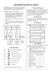
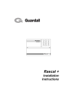
The control panel and the keypads are provided with 8 Led's for system status and alarm
information.
Operator Controls and Displays
ALARM LEDS (1 - 5)
MAINS 1
2
3
MAINS
LED
DAY
DAY
LED
4
1
2
3
4
5
6
7
8
9
*
0
#
NUMERIC
KEYPAD
5 TAMPER
RESET
BUTTON
TAMPER
LED
Rascal
Super
Operator Codes
Setting and unsetting of the system is normally inhibited unless a Personal Identification
Number (PIN) comprising of four digits is entered via the keypad.
The system is designed to recognise one PIN which may be changed at any time by the user.
Up to three optional keyswitches may be fitted to the system. This facility permits the
keyholder to full set, part set or unset the system. It does not allow access to other system
functions.
2. Normal Setting (Full Set)
Ensure all windows and doors are secure, check that all movement detectors are not
obstructed and proceed as follows.
Enter the four digit PIN code. The buzzer emits a steady tone. Leave the building by the
designated exit route. The system will set when the final door is closed and the exit time
expires.
3. Setting with Circuits Open
Should the user try to set the system with the circuits open, the system will not set. The
buzzer will emit a pulsed tone and the LED will flash for the open circuit. Enter the four digit
PIN code or press the # to abort setting. Investigate the cause of the problem and clear the
alarm. Once cleared start the setting procedure. If you do not abort the setting procedure
before the exit time expires the internal buzzer will sound. Enter the four digit PIN, the
relevant LED will flash, re-enter your PIN code and press the # key to reset.
4. Keyswitch Setting
Your system may be fitted with an optional three-position keyswitch which permits setting and
unsetting of the system.
The following describes setting the system using the keyswitch.
Insert the key and turn the key clockwise to
the
marking. Remove the key
and leave the premises by the designated
exit route. The system will automatically set
on expiry of the exit time.
Keyswitch Setting with Circuits Open
Should the user try to set the system with any circuits open, the system will not set. The
buzzer will emit a pulsed tone and the LED will flash for the open circuit.
Turn keyswitch on to
marking. Buzzer emits a pulsed tone.
Turn keyswitch to the
marking and Clear the open
circuit indicated by the flashing LED.
After clearing the open circuit the control panel can now be set. Turn keyswitch to
and leave the building by the designated route. The system will set when the exit time has
expired.
5. Part Setting
The part set function allows the user to set part of the system, while leaving certain circuits
isolated.
Enter the four digit PIN code then press the * key followed by the '0' key. The buzzer will
change tone and the LED's for the isolated circuits will flash. The part guard exit time will now
commence and once expired the system will part set.
If your system has not been programmed for part set then an error tone will sound.
Part Setting with Keyswitch
Your system can be part set via the keyswitch, this is achieved as follows.
Insert the key and turn clockwise to the
markings. The LED for the part set isolated
circuits will flash. Remove the key and the
part set exit time will commence. Once the
exit time is complete the panel will part set.
6. Home Setting
The Home set function allows the user to isolate circuits and set part of the system.
Enter the four digit PIN code the press the * key followed by the '6' key. The buzzer will
change tone and the LED's for the isolated circuits will flash. The part guard exit time will now
commence and once expired the system will Home set. If your system has not been
programmed for Home set an error tone will sound.
Note : Home set cannot be achieved via the keyswitch.
7. Setting with Isolated Circuits
The user can isolate circuits on setting the system providing the circuits have been
programmed to isolate, proceed as follows.
Enter the four digit PIN code, then press the * key followed by the number for the circuit you
wish to isolate. Once a circuit has been isolated the relevant LED for that circuit will flash.
The exit time will now commence and once completed the system will set.
If circuits are not programmed to be isolated then an error tone will be generated and the exit
time will continue.
8. Unsetting the System
On entering the premises the buzzer will emit a continuous tone. Proceed immediately to the
keypad via the designated entry route and unset the system as follows.
Enter the four digit PIN code within the preset entry time. The buzzer will stop and the system
will revert to 'DAY' mode. If the entry time has less than 10 seconds remaining a 'Hurry Up'
tone will be emitted.
Unsetting via the Keyswitch
On entering the premises the buzzer will emit a continuous tone. Proceed to the keyswitch via
the designated entry route and proceed as follows.
Insert the key and turn the key back to the
marking. The buzzer will stop and the
system will revert to 'DAY' mode.
9. Unsetting After an Alarm
On entering the premises after an intrusion a full alarm condition will exist. To clear the alarm
proceed immediately to the keypad via the designated entry route and proceed as follows.
Enter the four digit PIN code, the buzzer will emit an alternating two tone sound, the LED for
the circuit which first caused the alarm will be 'ON' and any subsequent alarm will be shown by
a flashing LED. Re-enter the four digit PIN code and press # key to reset the system.
If a reset is not allowed an error tone will be generated. Call your alarm installer for an
engineer reset.
Unsetting After an Alarm via Keyswitch
On entering the premises after an intrusion a full alarm condition will exist. To clear the alarm
proceed immediately to the keypad via the designated entry route and proceed as follows.
Insert the key and turn anticlockwise to the
marking. The buzzer will emit an alternating two
tone sound. The LED for the circuit which caused the
first alarm will be 'ON'.
Turn the key clockwise to the
and then back to the
system.
marking
marking to reset the
10. Chime Setting
The chime function is only available if it has been programmed for the circuits at installation.
To switch the chime function 'ON' or 'OFF' proceed as follows.
Enter the four digit PIN code then press the * key followed by the '9' then the '5' key. Any
circuits that have chime 'ON' will have the relevant LED 'ON'. To turn chime 'ON' or 'OFF'
press the key for the circuit you require to change. Press the * key to exit chime. If chime is
not available then an error tone will be generated.
11. Changing the PIN Code
Enter the four digit PIN code then press the * key followed by the '9' then the '1' key. The right
hand four LED's will be 'ON'. Enter your new four digit PIN code. As each number is
accepted an LED will go out. If your new code has been accepted then an accept tone will be
generated. If the new code is not accepted an error tone will be generated and you must pick
a new code. Until the accept tone is generated your old PIN code is still valid.
12. Reviewing the Event Log
With the system in the 'DAY' mode the user can review the event log. The event log is
organised into 'SET' and 'UNSET' events. The log will show the first to alarm and subsequent
alarms as well as isolated circuits. First to alarm is shown by the relevant LED being 'ON'.
Subsequent alarms are shown by the relevant LED flashing and isolated circuits are shown by
the relevant LED pulsing slowly.
The buzzer will sound whilst reviewing the 'SET' logs and the 'DAY' LED will be 'ON' whilst
reviewing the 'UNSET' logs. To view logs proceed as follows.
Enter the four digit PIN code then press the * key followed by the '9' then the '3' key. The log
routine will start with 'DAY 1 SET'. The remaining logs are viewed by pressing the relevant
key '2' for 2nd event '3' for 3rd etc. on to log 9. Pressing the '0' key gives the last to alarm
condition. To exit the logs press the * key.
The # key will alternate between 'SET' and 'UNSET' logs and can be used at anytime.
The log will automatically be exited if no keys are pressed for 30 seconds.
13. Sounder, Buzzer, Strobe & LED Test
Enter the four digit PIN code then press the * key followed by the '9' key. The buzzer will stop,
all the LED's will be 'ON' after 10 seconds the LED's will go 'OFF'. After the LED test the
buzzer will sound for 5 seconds followed by the sounder and then the strobe. After the test
the buzzer will emit an accept tone and revert to 'DAY' mode. The test can be terminated at
any time by pressing the * key.
14. System Walk Test
The user can "Walk Test" the system and test the operation of each detector circuit (with the
exception of personal attack and fire circuits) as follows.
Enter the four digit PIN code then press the * key followed by the '9' then the '4' key. The
buzzer will emit a low level steady tone. As each device is walk tested the internal buzzer will
give a loud pulsing tone to indicate correct operation of the device.
To exit walk test press the * key.
15. Daytime Tamper Alarm
The system automatically monitors the control panel, remote keypads, the external sounder
and all systems wiring and will automatically generate an alarm if an attempt is made to
interfere with any of these. However, if an attempt occurs during the 'DAY' mode then a local
alarm only is generated and the tamper LED will be 'ON'. To reset the system proceed as
follows.
Enter the four digit code. This will silence the buzzer and a two tone alternating sound will
now be emitted signifying a reset is required. Press the # key to reset the system.
Daytime tamper can also be reset via a keyswitch. Proceed as follows.
Insert the key and turn clockwise to the
marking, then back to the
marking.
This will silence the buzzer.
To reset the system and silence the two tone
alternating sound and clear the tamper LED turn
the key clockwise to the
marking and then
back to the
marking. This will
reset the system.
16. Your Circuit Description
Circuit
Alarm
Part
Set
Home
Set
Fire
PA
24 Hr
1
2
3
4
5
Installed By (Engineer Signature)..................................................
Date Completed......................................................
Exit Time............................................
Entry Time.........................................
Bell Duration......................................
Isolate
Allowed
Chime
Part No 320289-02
Guardall Limited
Lochend Industrial Estate
Newbridge
Edinburgh EH28 8PL
Tele: 031 333 2900