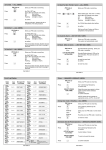
1
To instant Full Set / Part Set 1 and 2 (ALL USERS)
To Full Set — (ALL USERS)
PIN Code or
Enter your PIN code or smart key.
Press
the FULL SET key.
Exit time will start. System will set on
completion of the exit procedure.
Press
PIN Code or
Enter your PIN code or smart key.
or
Select setting type Full, Part 1 or 2.The
panel will set the selected part if the user is
authorised to do so.
The 2 (Pin) key selects instant setting
Press
or
2
To Part Set 1 — (ALL USERS)
If all zones are clear the panel will set, if
any zones are in alarm the panel will not
set and there will be a warning tone.
Enter your PIN code or smart key.
PIN Code or
Press
the PART SET 1 key.
Part set 1 exit time will start. System will
part set on completion of exit procedure.
To view the event log (MANAGER USER ONLY)
The event log can be viewed by a manager user only. The event log contains
the most recent events of the system.
PIN Code or
Enter a Manager PIN Code or smart key.
To Part Set 2 — (ALL USERS)
PIN Code or
Press
Enter your PIN code or smart key.
the PART SET 2 key.
Part set 2 exit time will start. System will
part set on completion of exit procedure .
NOTE:
In any of the setting methods a user will only be able to set/
unset the parts they have authority over. If a user attempts to
set/unset a part they do not have authority over then an error
tone will be emited from the keypad. If a user has authority
over a certain part and cannot set/unset the part then the
authority of the keypad may not be available for that part. If this
is the case consult the installer to rectify the problem.
Press
Press
6
Event Log.
1
✓
Confirms Event Log view.
Press
To print the log if a printer is attached.
Press
To scroll backwards through the event log.
Press
To scroll forwards through the event log.
Press
8
To display event number and time of event.
Press
9
To display text descriptor (if programmed).
Press
To exit event log at any time.
X
Note : Print log is not available on integrated (i) versions.
User Guide 2
User Guide 4
To Silent Full Set / Part Set 1 and 2 — (ALL USERS)
PIN Code or
Press
or
Press
or
Enter your PIN code or smart key.
Select setting type. Full, Part 1 or Part 2.
The panel will set the selected part if the
user is authorised to do so.
the 3 (Omit) key selects silent setting
3
Exit time will start. System will Set on
completion of exit procedure.
To Unset (No Alarm) — (NOT SET ONLY USER)
Press
PIN Code or
Enter your PIN code or smart key.
or
Select unsetting type. Full, Part 1 or Part 2.
The panel will unset the selected part if the
user is authorised to do so.
or
Note:
If a user only has authority for one part ,unsetting is automatic. user
will only be able to unset parts they are authorised to unset. If the user does not
wish to unset then press
X cancel at the unset prompt.
To Reset (After an Alarm)
PIN Code or
LED ON FOR ZONE
ACTIVATION
Press
Press
0
Event\Alarm Log Display
LCD Text
Display
Sounder/Strobe silenced. The display
scrolls through alarms.
✓
to reset the panel and
to confirm.
X
to revert to unset.
Note : If using a 2 x 7 segment display
reset required message.
User Guide 3
Status
LEDs
Twin
7-Segment
LCD Text
Display
Zone No
01 - 32
SECONDARY COMM OK
MAINS
TAMPER
DAY
FAULT
DUAL COMM OK
MAINS
TAMPER
DAY
FAULT
Twin
7-Segment
ZONE "?" ALARM
MAINS
TAMPER
DAY
FAULT
LINE FAULT
MAINS
TAMPER
DAY
FAULT
ZONE "?" SET FAIL
MAINS
TAMPER
DAY
FAULT
Zone No
01 - 32
PRIMARY COMM FAIL
MAINS
TAMPER
DAY
FAULT
USER "?" UNSET
MAINS
TAMPER
DAY
FAULT
User No
01 - 14
SECONDARY COMM FAIL
MAINS
TAMPER
DAY
FAULT
ZONE "?" OMIT
MAINS
TAMPER
DAY
FAULT
Zone No
01 - 32
DUAL COMM FAIL
MAINS
TAMPER
DAY
FAULT
SYSTEM TAMPER
MAINS
TAMPER
DAY
FAULT
ZONE "?" KNOCK
MAINS
TAMPER
DAY
FAULT
Zone No
01 - 32
ZONE "?" TAMPER
MAINS
TAMPER
DAY
FAULT
USER "?" CLK SET
MAINS
TAMPER
DAY
FAULT
User No
01 - 14
KEYPAD "?" TAMPER
MAINS
TAMPER
DAY
FAULT
USER "?" FULL SET
MAINS
TAMPER
DAY
FAULT
User No
01 - 14
DURESS
MAINS
TAMPER
DAY
FAULT
CALL ENGINEER
MAINS
TAMPER
DAY
FAULT
USER "?" PART 2 SET
MAINS
TAMPER
DAY
FAULT
User No
01 - 14
TEST CALL
MAINS
TAMPER
DAY
FAULT
ZONE "?" SOAK
MAINS
TAMPER
DAY
FAULT
Zone No
01 - 32
REMOTE LOCKOUT
MAINS
TAMPER
DAY
FAULT
MAINS FAIL
MAINS
TAMPER
DAY
FAULT
KEYPAD "?" LOCKOUT
MAINS
TAMPER
DAY
FAULT
LOW BATTERY
MAINS
TAMPER
DAY
FAULT
ENGINEER ACCESS
MAINS
TAMPER
DAY
FAULT
USER "?" PART 1 SET
MAINS
TAMPER
DAY
FAULT
WALK TEST
MAINS
TAMPER
DAY
FAULT
PRIMARY COMM OK
MAINS
TAMPER
DAY
FAULT
CLOCK EDIT
MAINS
TAMPER
DAY
FAULT
DATE STAMP
MAINS
TAMPER
DAY
FAULT
CONCENTRATOR TAMPER
MAINS
TAMPER
DAY
FAULT
— (NOT SET ONLY USER)
Sounders/Strobe operating. Enter your
PIN code or smart key.
Status
LEDs
will be displayed depicting a
Zone No
01 - 32
KEYPAD
No. 1 - 8
User No
01 - 14
User Guide 5
KEYPAD
No. 1 - 8
CONC.
No. 1 - 8
User Authority setting/unsetting options(MANAGER USER)
Text (MANAGER USER ONLY)
The user authority is only available to a Manager user. User 01 is defaulted as a
manager and this cannot be changed. To assign authority proceed as follows :
Text can be customised using an LCD keypad. Text can only be customised
by a Manager User.
PIN Code or
XXXX or
Press
Enter Manager PIN code or smart
key.
then
this selects the authority programming
(Mains/Tamper LEDs on)
select the user number whose authority is
to be set
(mains, Tamper & Day LEDs on once User
is selected)
6
✓
Press
0
2
to
1
Press
Press
4
0
1
1 = Manager or
2
2 = Ordinary or
3
3 = Set only or
4
4 = Duress or
✓
to confirm selection
Will be displayed if no setting/unsetting
authority has been assigned.
Press
0
0 = Standard authority
1
1 = P1 authority
2
2 = P2 authority
3
3 = Full authority
✓
to confirm selection
then
to select group text or
7
✓
Press
then
to select user text
8
✓
9
Press
then
to select zone text
✓
0 = OFF or
AREA = OFF
Press
Press
Enter manager PIN code or smart key.
Once group, user or zone text is entered, the following keys allow the selection
of certain characters or functions.
1
2
3
4
5
6
7
8
9
0
-
Select A
Select M
Select Z
Select a
Select m
Select z
Select 1
Select 9
Select .
Deletes text to the right of the
flashing character
Moves up the alphabet
Moves down the alphabet
Selects/confirms choice of character
Confirms whole text string
Reverts to previously selected text
√ X Default Text
Zone No
1
2
3
to
32
Text
User No
zone 1
zone 2
zone 3
zone 32
1
2
3
to
14
Text
User 1
User 2
User 3
Group
1
2
3
4
Text
Part 1 set
Part 2 set
Full set
System unset
User 14
The LCD Keypad can also be used for displaying the default or customised text when required.
When chime, omit, walk test or alarm log are being displayed, pressing key 9 will display zone
text and when set indications are selected then group text is displayed.
User Guide 6
UserAuthority setting/unsetting options (MANAGER USER)
The setting/unsetting authority is only programmable by a Manager user.
Setting/unsetting authority can be assigned to each user. After selection of
authority level for the user (see above) the user can be assigned ,P1, P2 or Full.
Full authority will also allow setting/unsetting of P1 or P2. To assign setting/
unsetting authority proceed from setting the user authority and assign setting/
unsetting authority.Once setting/unsetting authority has been assigned the user
will only be able to set/unset the parts they have been authorised to set/unset. If
a user with authority for P1 tries to set/unset P2 or Full then an error tone will be
emitted from the keypad.It is critical to the correct operation of the system
that each user is fully aware of the authority they have and the setting/
unsetting authority they have been assigned.It should be noted that the user
must also know which keypads have authority over which parts of the system
as this has a major impact on what can be achieved on the system.
Note : The action of selecting OFF for a User authority will change the PIN
code to factory default.
If Duress User authority is selected, when logging on to change the PIN,
a duress alarm will be created.
User Guide 8
Walk Test — (MANAGER USER)
PIN Code or
Press
Press
0101 (MANAGER FIXED)
0202 (NO AUTHORITY)
0303 (NO AUTHORITY)
|
|
1414 (NO AUTHORITY)
User Guide 7
✓
to confirm.
X
the cancel key to exit.
Sounder Test — (MANAGER USER)
PIN Code or
Press
5
✓
Enter manager PIN code or smart key.
the 5 (Sndrs) key followed by
to confirm.
Speaker will operate for 60 seconds or
Press
DEFAULT PIN CODE
DEFAULT PIN CODE
DEFAULT PIN CODE
|
DEFAULT PIN CODE
the 4 (Walk) key followed by
Display will scroll through untested zones.
If OFF is selected for setting/unsetting authority then the system will
unset everything that is set when the Pin code is entered rather than
controlling individual parts that are assigned to the user through setting/
unsetting authority.
USER 01
USER 02
USER 03
|
USER 14
4
Detector test is now enabled.
Manager SET / UNSET / OMIT / CHIME / CHANGE PIN / TEST /
CHANGE TIME / EDIT TEXT / VIEW LOG / REMOTE ACCESS
Ordinary SET / UNSET / OMIT / CHIME / CHANGE PIN
Set Only SET / CHANGE PIN
Duress AS ORDINARY BUT GENERATES PA TX OUTPUT
IN DEFAULT ONLY USER 01 HAS AUTHORITY. THE AUTHORITY FOR
USER 01 IS SET FOR MANAGER AND THIS AUTHORITY CANNOT BE
CHANGED.AS EACH USER IS REQUIRED THEN THE AUTHORITY
SHOULD BE ASSIGNED, AFTER THIS IS COMPLETE THE PIN CODE
SHOULD BE CHANGED FROM DEFAULT.
Enter manager PIN code or smart key.
✓
✓
X
to move on to sounder which will operate
for 60 seconds or
to move on to strobe which will operate
for 60 seconds or
the cancel key to exit.
Exit Faults
If a zone alarms during the exit time, the setting tone will change and the
fault LED will be on. If the zone does not clear by the end of the exit time, the
system will not set and the faulty zone will be indicated on the zone LED's when
the User logs on.
User Guide 9
Time Change — (MANAGER USER ONLY)
The time can be changed by a Manager User only. To change time, proceed as
follows
Press
6
Press
3
Enter manager PIN code or smart key.
LED
STATUS
Mains
(GREEN)
then
✓
the current time will be displayed with the
first digit flashing. Enter the new time
directly to move to the next field.
✓
to confirm.
The clock on the control panel can be adjusted to add or remove a programmed
number of seconds each day. The adjustment is allowed to cater for a slow or
fast clock. To adjust the clock it must be known how much adjustment is
required ie the number of seconds the clock loses or gains per day. The
adjustment is automatic at midnight each night and does not have to be carried
out each day.
6
3
✓
Press
Mains Present
Power Failed
Running off battery
ON
OFF
FLASH
System may be optioned to show
the day LED status when no
users are logged on.
Panel ready to set
The panel is not ready to set.
Setting started
ON
FLASH
OFF
Will be on if the panel is reset when
a PA, Fire, 24 hr or tamper circuit is
still open. Will also be on if a fault is
present when setting.
Programmer logged on.
Zone clear no setting problems
Tamper
(RED)
ON
System in tamper alarm condition
Zones
(RED)
ON
Shows the zones which are
selected for setting. Also shows
zones which have alarmed in alarm
log.
Indicates the zones which are not in
the setting group or zones which are
omitted.
To adjust the clock proceed as follows:
Press
ON
OFF
FLASH
Day
(GREEN)
Fault
(AMBER)
then
the current time will be displayed with
the first digit flashing.
Clk adjust = + 0
Enter adjustment in seconds.
Press
Press
To change from adding time to removing
time.
✓
FUNCTION
OFF
to confirm adjustment.
NOTE: It is essential that the time adjust is only used if the amount of
adjustment is known. The adjustment should only need to be carried out
once.
Guardall Limited
Lochend Industrial Estate
Newbridge
Edinburgh EH28 8PL
Part No. 320519-OD
User Guide 16
User Guide 14
Managed Reset Operation (LCD ONLY)
Managed reset is only required if the panel has been configured for engineer
reset and managed reset is turned on. Following an alarm, the panel can be
unset by entering a valid PIN code or smartkey. This will silence the sounders.
To reset the Tx channels follow reset after an alarm procedure. Once unset,
the panel cannot be set until a managed reset code is provided. If an attempt to
Full Set or Part Set 1 or 2 is attempted, the LCD keypad will display a 5 digit
number. Your alarm company should be contacted with this number and they
will issue a reset PIN code. Entering this PIN code will reset the panel and allow
the system to be set again. The Reset PIN code can only be entered when RST
number is displayed e.g.
PIN Code or
Enter your PIN code or smart key.
MAN RESET RQD
Press
RST CODE = ?????
Press
******
will be displayed on LCD keypad
to set system. A 5 digit number will be
displayed. Contact the alarm company for
PIN code and enter the 6 digit number
If sucessful the Fault LED will extinguish
and the panel can now be set.
THE PANEL CAN BE RESET AT ANY TIME BY
ENTERING A VALID ENGINEERING CODE.
User
Guide
IMPORTANT NOTE:
User Guide 15
THE CONTROL PANEL CAN BE PROGRAMMED TO ALLOW LOG ON BY
ENTERING A VALID PINCODE OR ENTRY OF A VALID PINCODE
FOLLOWED BY ✓
CONFIRM. PLEASE CONSULT YOUR INSTALLER
TO VERIFY WHICH METHOD OF LOG ON THE CONTROL PANEL HAS
BEEN PROGRAMMED TO ACCEPT.
© Guardall Limited 1996
PIN Code or
LED FUNCTIONS
KEYPOINT USE
Remote Authorisation — (MANAGER USER ONLY)
If programmed for remote access authorised by the manager user, then the
manager must allow remote access as follows :
To Full Set
Enter your smart key.
the FULL SET key. Exit time will
start. Remove your smart key and leave
by the designated exit route. System will
set on completion of the exit procedure.
Press
PIN Code or
Press
6
2
to select the authorisation program
0
for remote access 'OFF' or
1
for remote access 'ON'
✓
to confirm selection.
To Part Set 1
Press
then
✓
Press
Enter your smart key.
the PART SET 1 key. Part set
exit time will start. Remove your smart key
and the system will part set on completion
of the exit procedure.
Enter manager PIN code or smart key.
Press
When remote access 'ON' is selected, remote access is authorised for a 10
minute window during which time remote access must be carried out.
Chime — (MANAGER & ORDINARY USERS)
To Part Set 2
PIN Code or
Enter your smart key.
the PART SET 2 key. Part set
exit time will start. Remove your
smart key and the system will part set on
completion of the exit procedure.
Press
1
Press
✓
SELECT ZONES
FOR CHIME
Enter your PIN code or smart key.
the 1 (Chime) key followed by
to confirm key.
Select the zones you require to chime
e.g. 01 for Zone 1 etc.
To Unset (No Alarm)
Enter your smart key. The system
will automatically unset.
To Reset (After an Alarm)
Sounder/Strobe operating.
Enter your smart key.
Sounder/Strobe silenced.
Fault LED on. Remove key and go to an
LCD/2X7 segment keypad to reset the
system.
Press
0
de-selects chime for the zone.
Press
1
selects chime for the zone.
Press
✓
to confirm selection
Press
X
to exit or select another zone you require to
chime.
Note : Only appropriate zones can have chime. This excludes PA, 24 HR
and Fire.
User Guide 10
2 x 7 Segment Keypad Displays
Reset required
This will be displayed when a reset is required after an alarm.
Full Set
This will be displayed when the user selects
Full Set.
Part 1 Set
This will be displayed when the user selects
Part 1 Set.
Part 2 Set
This will be displayed when the user selects
Part 2 Set.
Call Engineer
This will be displayed when an engineer reset is required.
Battery Test
This will be displayed when the panel performs a battery test.
Unset
This will be displayed to prompt the user to unset the parts
they are authorised to unset.
NoAuthority
This will be displayed if an attempted function is not
available to the user.
Pin Clash
This will be displayed if a Pin Clash occurs.
Push Button
This will be displayed if a push button set is required.
Keypad Busy
This will be displayed if another keypad is in use.
Pin Prompt
This will be displayed for new pin code entry followed by
the number of digits required for the new Pin code.The
number of digits will decrease as new ones are entered.
User Guide 12
Change User Code or Smartkey — (ALL USERS)
PIN Code or
Press
2
✓
the 2 (PIN) key followed by the
to confirm.
YYYY or
Enter your new PIN code or a new smart
key.
YYYY or
Re-enter your new PIN code or smart key.
X
Press
Enter your PIN code or smart key.
to revert to unset.
Omit Zone (One Set Period Operation) — (MANAGER & ORDINARY USERS)
PIN Code or
3
Press
✓
SELECT ZONES
FOR CHIME
Press
Enter manager PIN code or smart key.
the 3 (Omit) key followed by the
to confirm
Enter zone number to omit
e.g. 01 for Zone 1 etc. then
0
to keep zone active or
1
to omit the zone
Press
✓
to confirm selection
Press
X
to revert to unset.
Note : only zones programmed as omit can be omitted.
Smart keys
Smart keys must be programmed for each system. Smart keys will not
operate until they are programmed. To programme a key follow the PIN code
change routine.Once the smart key has been programmed it must be
remembered that the key will now replace the pin code.
User Guide 11
User Guide 13