1
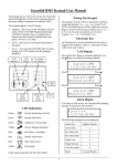
1
2
3
4
5
6
7
8
9
*
0
#
⊕
⊕
Rascal +
Rascal +
Installation
Instructions
RASCAL + INSTALLATION INSTRUCTIONS
Introduction
The Rascal+ is a keypad operated microprocessor alarm control unit. It has a host of
enhanced features not normally found on a control panel of this size. It is provided with a
dedicated final Entry/Exit, Intermediate entry circuit, and two alarm zones. A common 24hr.
circuit and a separate Personal Attack circuit are also provided.
Mechanical
It is housed in an attractive, durable 3mm thick polycarbonate box. To gain access to the
printed circuit board, remove the lid fixing screws. Cable entry points and routing channels
are provided on each side of the box.
Fixing
A top keyhole fixing is provided. Fix top securing screw, hook onto the top keyhole and mark
the position of the other holes. Remove the unit. Drill and plug the remaining fixings then
secure to the wall.
Mains Wiring
CAUTION......... THE ELECTRICAL INSTALLATION SHOULD COMPLY WITH THE
LATEST I.E.E. WIRING REGULATIONS. IF IN DOUBT CONSULT A QUALIFIED
ELECTRICIAN.
The supply should be taken from an unswitched fused spur outlet. A three-way mains
terminal block is fitted below the printed circuit board.
Other Wiring
All other wiring should use British Standard security cable to the other terminals as listed in
the connection chart. The routing of these cables should be kept away from sources of
possible interference. i.e. fluorescent lights, central heating thermostats and fuse boxes etc.
First Powering Up
When power is first applied the alarm will come on in a tamper condition. Enter the factory
default code (1-2-3-4) to stop the sounder then press the # to reset to normal.
Display Interpretation
The first zone to alarm will indicate with a continually lit LED. Any secondary or subsequent
alarm zones will be indicated by a fast flashing LED. Any isolated zones will be indicated by a
slow flashing LED.
Operation Notes
There are three 'set' positions. Full set arms all zones. Two part sets are provided both
isolate Zone 2 and make the IX circuit into a second delayed entry circuit. Part set (* and 0)
allows the external bell to ring. Home set (* and 4) disables the external bell and strobe.
1. Full Set
Enter the user code (default 1-2-3-4). The sounder will emit a steady tone and the exit timer
will start. Leave the protected area by the appropriate route.
2. Part Set
Enter the user code then press the * and 0 keys. The sounder will emit a steady low tone and
the exit timer will start. Zone 2 will be isolated and it's LED will pulse. The IX circuit will
become a second delayed entry circuit. Leave the protected area by the appropriate route.
With part set the external bell will sound in the event of an alarm.
3. Home Set
Enter the user code then press the * and 4 keys. The sounder will emit a steady low tone and
the exit timer will start. Zone 2 will be isolated and it's LED will pulse. The IX circuit will
become a second delayed entry circuit. Leave the protected area by the appropriate route.
With home set the external bell and strobe are disabled.
4. Setting with Individual Circuits isolated.
Enter the user code. The sounder will emit a steady tone. Press the * key and the number
key for the zone to be isolated. The LED for that zone will pulse. The IX zone (intermediate
entry) is isolated by key number 3.
If more than one zone is to be isolated then each zone number must be preceeded by the *
key i.e to isolate zones 1 and 2 enter code followed by *1 then *2.
5. Any Exit Faults
This will cause the exit timer to halt and the sounder to pulse. The circuit LED will light. When
the fault is cleared the LED will go out and the exit timer will restart. The alarm may not be
'set' with a fault present. The minimum exit time folllowing an exit fault will be 5 seconds.
6. 24hr Tamper
When the panel is set a tamper alarm will activate the internal and external sounders and the
strobe. When the panel is not set (during the day) a tamper alarm will activate the internal
sounder only. In both cases the tamper LED on the control panel will be lit when unset. Reset
the panel and clear the fault.
7. Personal Attack
In alarm both the internal and external sounders, and strobe will operate. The PA LED on the
control panel will be lit. Reset the alarm and reset the PA button.
8. Stopping the Bells
Following an alarm enter the user code to stop the bells or sounders.
9. Entry
Upon entry if all is clear the sounder will emit a steady tone. In the event of there having been
an alarm condition which has auto reset the sounder will pulse. In the last remaining 15
seconds of the entry time the sounder will emit a rapid pipping 'entry hurry' up tone, go
directly to the alarm and enter the user code.
10. Resetting
To reset following any alarm condition, enter the user code. The sounder will emit a
'bip-bop' reset required sound. Press the # key to reset. If either the tamper or PA circuits are
in fault the LED's for those zones will flash. Reset the PA push or clear the tamper fault.
11. Bell Test
Key In
User Code
Key Numbers
*9
Conditions
All the LEDs will light
There will be a 10 second pause then :The internal sounder will operate for 5 seconds.
The external bell will operate for 5 seconds.
The strobe (where fitted) will operate for 5 seconds.
The control will then automatically revert back to day mode.
12. Security Code Programming
The control unit has a 4 digit security code that is programmable only by first entering the
original code.
Key In
Key Numbers
User code
*91
Note : The factory default code is (1-2-3-4)
Enter
New user code
13. Reading Logs
The Rascal+ includes a logging mode which allows a recall of the last two set and unset
events.
Key In
User code
Key Numbers
*93
Conditions
A steady tone and the display indicating
the last set state.
TO VIEW ANY DAY'S LOG
Key
View
1
Log 1 'SET'
2
Log 2 'SET'
Key
#
#
View
Log 1 'UNSET'
Log 2 'UNSET'
The log is organised as 'SET' and 'UNSET' events. All events are recorded. The first to alarm
is shown by the relevant LED being lit continuously. Subsequent alarms as shown by a fast
pulse of the relevant LED. Any zones isolated are shown by a slow pulse on the relevant
LED.
When this option is first entered the display will be showing log 1 'SET' state. To display the
'UNSET' (Day) conditions press the # key. The buzzer will sound whilst viewing the 'SET'
logs. Any key press error will cause a return to viewing Log 1 'SET'.
To revert back to day mode press the * key.
14. Walk Test
Key In
User code
Key Numbers
*94
Conditions
A steady tone
The zone alarm devices may now be operated. The display will show the zones operated and
a high level sounder will follow the status of the zone under test.
To revert back to day mode press the * key.
Note : PA or tamper circuits may not be walk tested. An alarm condition will be generated
upon operation.
15. Chime Control
The chime is a tone associated with the entry/exit zone (FX) and can be used to alert the
user to any intrusion during the unset times. The chime can be turned on and off while the
alarm is not set as follows :
To enable, press * followed by the 4 key. The FX LED will light. Press the * key to revert back
to day mode. To disable, press * followed by the 4 key. The FX LED will go out. Press the *
key to revert to day mode.
To check the Chime simply press the * key. If the FX LED lights the chime function is on. If
the LED is off then the chime function is off. Always press the * key to revert to day mode
when finished. If the * key is not pressed after 15 seconds have expired, the control panel will
revert to day mode automatically.
CONTROL OUTPUTS
1. ID - Output
This is a supply negative (0V) feed for Viper detectors, shatterbox and smoke detectors
which require a temporary removal of power to clear their alarm memories. The terminal
pulses off when the alarm is turned to 'Set' (1/2 second pulse) or at 'Reset' (3 second pulse).
Current limit 50 mA.
2. L+ Latch Line (Set/Unset)
This output is for controlling latching PIR detectors. The line goes to 12V when 'set' and
returns to 0V when unsetting occurs.
3. 12V Auxiliary
This is the supply for PIR or other powered detectors. The maximum permissible
load is 150 mA
4. Battery Fuse
The battery fuse is a 20mm 1 Amp anti surge type.
Connections
Terminal Group 1.
Alarm connections
No
Name
Description
1&2
24 Tamper
Common tamper loop
3&4
PA
Personal attack circuit
5&6
1
Alarm Zone 1
7&8
2
Alarm Zone 2
9 & 10
IX
Intermediate entry circuit
11 & 12
FX
Entry/Exit circuit
Terminal Group 2
No
13
14
15
16
17
Name
EXT+
SPKIDL+
ST-
18
19
SH-
20
21
22
23
24
+
C
D
AUX +
AUX -
Power and Control
Description
Extension speaker connections
Fit a maximum of 2 extra 16 Ohm speakers
Switched negative voltage feed
Set line for latching detector (each to alarm)
Strobe switched negative. Fit a maximum of two low
current strobes.
Bell signal negative
Self actuating siren hold of negative. This terminal
goes open circuit in alarm. Bell relay contacts rated at
1A max.
Bell hold off positive supply
Remote keypad clock signal
Remote keypad data signal
Auxiliary nominal 12V positive
Auxiliary nominal 12V negative. Maximum
current load 150 mA.
OPTIONS
1. Quick Set
Cut link A for quick set in part guard. The exit time will be 5 seconds.
2. Buzzer Volume
Cut link B to reduce the buzzer ( low level sounder) volume.
Sounders and Strobe
Bell cut off is permanently selected. The internal sounder and strobe operation are
modified when the bell ring time is set to 10 mins or less.
Note : Fit a maximum of two low current strobes.
Fit a maximum of two 16 Ohm extension speakers (in parallel).
Bell Time Set 10 Mins or Less
If a zone is in fault for 10 mins, that zone will be isolated permanently.
If a zone is in alarm for shorter than the bell time the internal sounder and strobe will cut off
with the bells at the end of the preset bell time. If a zone is in alarm for longer than the bell
time the bell will stop at the end of the bell time and the internal sounder will stop when the
zone resets or at 10 mins if the zone remains in fault.
Bell Time Set 11 Mins or Longer
If a zone is in alarm for less than 10 mins when the bell timer has finished the bell and the
internal sounder will stop. The strobe will continue until the control panel is switched off.
Timing Controls
EXIT TIME
ENTRY TIME
BELL RING TIME
10 secs to 120 secs approximately
10 secs to 120 secs approximately
1 min to 40 mins approximately
With all controls to increase the time, turn clockwise
Timing Adjustments
Exit, entry and bell controls are scanned at 5 min. intervals. When altering the times make
the adjustment and enter the user code. Wait 5 seconds then press the # key. At this point
wait a further 20 seconds for the controls to be scanned. The new settings will then be
effective.
Standard SAB
Terminations
Name
Number
24 Tamper
Bell +
Bell S24 Tamper
1
20
18
2
Universal SAB 1
Terminations
Name
Number
+
SR
- 12V Hold Off
+12V Hold Off
Bell +
Bell Ring Negative
Bell STamper Return Negative 24 Tamper
20
18
2
24 Tamper
1
+
SR
S+
F
Universal SAB 2
Terminations
Name
Number
24 Tamper
Bell +
Bell S24 Tamper
1
20
18
2
24 Tamper
ST -
2
18
20
1
17
Flashguard
Terminations
Name
Number
+
SR
S+
F
- 12V Hold Off
ST +12V Hold Off
Bell +
Bell Ring Negative
24 Tamper
Tamper Return Negative
Bell Ring Positive
Bell S Tamper Feed
24 Tamper
CQR Soundpac
Terminations
Number
Name
24 Tamper
Bell S Bell +
- 12V Hold Off
+12V Hold Off
Bell Ring Negative
Tamper Return
Bell Ring Positive
Tamper Feed
1
2
3
4
5
6
+ Tamper Return
- Tamper Return
-ve Trigger
+ 12V Hold Off
+12V Hold Off
+ LED Feed
7
8
9
10
11
No Connection
NI - CAD Charge
NI - CAD Battery
0V Ground
-ve Strobe Trigger
17
20
1
18
2
Terminations
Number
Name
24 Tamper
Bell S Bell +
2
18
20
+
A
D
B
F
Strobe
- 12V Negative Hold Off
+12V Positive Hold Off
Bell Ring Negative
Tamper Return
CQR Integra
A/T Ret
Siren Trig Supply +
Select A/T - Fit Link
Select A/T c
Fit Enable Battery Link
24 Tamper
ST -
1
17
Supply STR -
Notes:
1.
2.
3.
When connecting an SAB unit the lid tamper will cause the bell to ring from the
SAB battery.
Terminal 1 should always be used as the start of the tamper loop or the negative hold
off feed for SAB unit.
The tamper return from the Sab unit should be wired in series with all other
tamper connections and connected into terminal 2.
1
MIN
RV3
ENTRY BELL
RV2
MAINS
FX
IX
24
PA
1
TAMPER LOOP
TAMPER
2
IX
FX
1
PA
2
IC2
BELL
STROBE
EXTENSION
SPEAKER
BELL TAMPER
PRESSURE
MAT
BOX SPEAKER
LID TAMPER
Cut for PG QS
OPTION 1
TAMPER
⊕ ⊕ ⊕ ⊕ ⊕ ⊕ ⊕ ⊕ ⊕ ⊕ ⊕ ⊕ 12
EXIT
RV1
ULN2003
MIN
OPTION 2
Cut for low
volume
BOX
SPK
+
L
S
T
IC3
S
H
RLY1
KEYPAD
CONNECTOR
+
BATT 1A
+
AUX
+
-
BATT
a.c.
+
EXT
SPK
BELL
C
D
⊕ ⊕ ⊕ ⊕ ⊕ ⊕ ⊕ ⊕- ⊕ ⊕ ⊕ ⊕ ⊕ 24
13
I
D
BATTERY FUSE
47R
270R
2K2
TIMING CONTROLS
393
Part No 320232-04
MIN
7812
Guardall Limited
Lochend Industrial Estate
Newbridge
Edinburgh EH28 8PL
Tele: 031 333 2900
+
TAMPER
DATA
CLOCK
- 12V SUPPLY
+
}
KEYPAD
CONNECTIONS
TRANSFORMER
CONNECTOR