1
PMX Series Mixer
PMX Series Mixer
SPEAK OUTPUTS
Min load 4Ω
2.1 Mono channels
L
2.4.3 AMP Output
2.1.1 Microphone and line inputs
+1
MIC
-1
R
Each mono input channel offers a balanced microphone
input via the XLR connector and also features switchable
+48V phantom power supply for condenser microphones.
The PMX preamps provide undistorted and noised-free gain
as is typically known only from costly outboard preamps.
MIC
LINE IN
LOW CUT
75Hz
18 dB/Oct
+10 +10 -40 +60
TRIM
1
dB/dBu
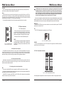
Fig. 2.1: Connectors and
controls of mic/line inputs
+2
LINEIN
Each mono input also features a balanced line input on a
1/4" connector. Unbalanced devices (mono jacks) can also
be connected to these inputs.
please remember that you can only use either the
microphone or the line input of a channel at any one
time. You can never use both simultaneously!
LOW CUT
The mono channels of the mixing consoles have a highslope LOW CUT filter for eliminating unwanted, low-frequenty
signal components (75 Hz, 18 dB/octave).
TRIM
Use the TRIM control to adjust the input gain. This control should always be turned fully counterclockwise whenever you connect or disconnect a signal source to one of the inputs.
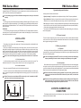
Fig. 2.16: AMP output
2.4.4 Heat removal system
DO NOT OBSTRUCT AIR VENTS
HEAT REMOVAL SYSTEM
This is the mixer's stereo amp fan refrigeration system.
It works with low speed in normal temperature (≤45℃).
When it is higher than 45℃, it will quicken up.
Fig. 2.17: Heat removal system
Caution! You must never use unbalanced XLR connectors (PIN 1and 3 connected) on the
MIC input connectors if you want to use the phantom power supply.
SERIAL NUMBER
Please note the important information on the serial number given in chapter 1.3.3.
2 4 - BIT MULTI - FX PROCESSOR
FX
FOOTSW
EQ
0
PHONES
HIGH
00
03
06
09
10
13
16
19
20
27
30
SMALL HALL
MID HALL
BIG HALL
CHURCH
SMALL ROOM
MID ROOM
BIG ROOM
CHAPEL
PLATE
SPRING
GATED REV
36
40
44
48
49
50
59
60
66
70
74
REVERSE
EARLY REFL
AMBIENCE
STADIUM
AMBIENCE FX
DELAY
ECHO
CHORUS
FLANGER
PHASER
PITCH SHIFT
80
82
84
86
88
90
91
92
94
96
98
CHORUS & REVERB
FLANGER & REVERB
PHASER & REVERB
PITCH & REVERB
DELAY & REVERB
DELAY & GATED
DELAY & REVERSE
DELAY & CHORUS
DELAY & FLANGER
DELAY & PHASER
DELAY & PITCH
12 KHz
-15
0
+15
MID
2.5 KHz
-15
0
+15
LOW
80 Hz
-15
24-BIT DUAL ENGINE DSP
CLIP
-3
3.DIGITAL EFFECTS PROCESSOR
24-BIT MULTI-EFFECTS PROCESSOR
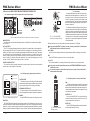
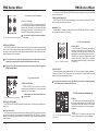
Here you can find a list of all presets stored in the multieffects processor. This built-in effects module produces
high-grade standard effects such as reverb, chorus, flanger,
delay and various combination effects. The integrated
effects module has the advantage of requiring no wiring.
This way, the danger of creating ground loops or uneven
signal level is eliminated at the outset, completely simplifying the handing.
-6
-10
-15
-20
LEVEL
24-BIT A/D & D/A CONVERTER
PROGRAM
(PUSH)
+15
Fig. 2.2: Panorama and routing controls
4
The upper (HI) and the lower band (LO) are shelving
filters that increase or decrease all frequencies above
or below their cut-off frequency. The cut-off frequencies
of the upper and lower band are 12 kHz and 80 Hz
respectively. The mid band is configured as a peak filter
with a centre frequency of 2.5kHz
Note: Keep the windhole free, or the equipment will be too
hot and turn to protection in advance.
After the phantom power supply has been switched on, do not connect microphones to the
mixer (or the stagebox/wallbox). Connect the on. In addition, the monitor/PA loudspeakers
should be muted before activating the phantom power supply. After switching on, wait approx.
One minute to allow the system to Stabilize.
2.1.2 Equalizer
All mono input channels include a 3-band equalizer. All bands provide boost or cut of up to 15dB. In the
central position, the equalizer is inactive.
The circuitry of the British EQs is based on the technology used in the bast-known top-of-the-line
consoles and providing a warm sound without any unwanted side effects. The result are extremely musical
equalizes which, unlike simple equalizers, cause no side effects such as phase shifting or bandwidth
limitation, even with extreme gain settings of ±15 dB.
AMP OUTPUT
This speakon socket is for stereo Amp L/R output. It's
used to connect speaker cabinet by speakon NL 4FC.
Note: Min Load 4Ω
Please mute your play back system before you
active the phantom power supply to prevent switchon thump being directed to your loudspeakers.
Please also note the instructions in chapter 2.4.2
“Voltage supply, phantom power and fuse”.
BAL
OR
UNBAL
-2
These effect presets are designed to be added to dry
signals. If you move the FX TO MAIN control, you mix the
channel signal (dry) and the effect signal.
Fig. 3.1: Digital effects module
13