1
PMX Series Mixer
PMX Series Mixer
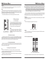
2.4 Rear view of PMX1204FX/PMX1404FX/PMX1604FX/PMX1804FX
1
AUX
0
2.4.1 main mix outputs, Alt 3-4 outputs and control room outputs
ALT 3-4
OUTPUTS
MAIN OUTPUTS
R
L
ALT 3-4 OUTPUTS
L
4
3
CONTROL ROOM OUT
R
L
-
+15
8
MAIN OUTPUTS
PIN 2 = HOT / PIN 3 = COLD
R
POST
PRE
4
0
2
2.1.3 Aux sends
Aux sends take signals via a control from one or more
channels and sum these signals to a so-called bus. This
bus signal is sent to an aux send connector and then
routed, for example, to an active monitor speaker or an
external effects device. The return from an external effect
device can then be brought back into the console via the
aux return connectors.
PIN 2 = HOT / PIN 3 = COLD
FX
PMX1404FX/
PMX1604FX/
PMX1804FX
CONTROL ROOM OUT
PMX1204FX
Fig. 2.14 Main mix outputs, Alt 3-4 outputs and control room outputs
MAIN OUTPUTS
The MAIN outputs carry the MAIN MIX signal and are on balanced XLR connectors with a nominal
level of +4dBu.
ALT 3-4 OUTPUTS
The ALT 3-4 output are unbalanced and carry the signals of the channels that you have assigned to
this group using the MUTE switch. This can be used to route a subgroup to a further mixing console for
example, or it could be used as a recording output working in tandem with the main output. This means
you could record to four tracks simultaneously. The icing on the cake, so to speak, is that you could
connect Y-cables to these four outputs and then connect your 8-track recorder in such a way that you
have 2 x 4 tracks. (E.g. Channel 1 feeds track 1and track 2, etc.). In the first recording pass, you record
on track 1, 3.5 and 7 and in the second pass, on tracks 2, 4, 6 and 8.
CONTROL ROOM OUTPUT
The control room output is normally connected to the monitor system in the control room and provides
the stereo mix or, when required, the solo signal.
-
+15
8
L
R
3
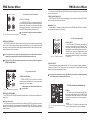
Fig. 2.3: The AUX SEND
controls in the channel strips
For situations which require effects processing, the aux
sends are usually switched post-fader so that the effects
volume in a channel corresponds to the position of the
channel fader. if this were not the channel would remain
audible even when the fader is turned to zero. When setting
up a monitor mix, the aux sends are generally switched
to pre-fader, i.e. they operate independently of the position
of the channel fader.
Both aux sends are mono, are sourced after the equalizer and offer up to +15dB gain.
If you press the MUTE/ALT 3-4 switch, aux send 1 is muted, provided that it is switched postfader. However, this does not affect the aux send 2
AUX 1 (MON)
Aux send 1 can be switched pre-fader and is thus particularly suitable for setting up monitor mixes.
PRE
When the PRE switch is pressed, aux send 1 is sourced pre-fader.
Aux 2 (FX)
The aux send labeled FX is for sending to effects devices and is thus set up to be post-fader.
If you wish to use the internal effects processor, the STEREO AUX RETURN 2 connectors
should not be is use.
You can also connect an external effects processor to aux send 2, however the internal
effects module will be muted.
2.4.2 Voltage supply, phantom power and fuse
AC 100-120V ~ 60Hz
T10AH
AC 200-240V ~ 50HZ
T5AH
POWER
ON
ON
PHANTOM
Fig. 2.15: Voltage supply and fuse
PAN
FUSE HOLDER
The console is connect to the mains via the cable supplied
which meets the required safety standards. blown fuses must
only be replaced by fuses of the same type and rating.
IEC MAINS RECEPTACLE
The mains connection is via a cable with IEC mains connector. An appropriate mains cable is supplied with equipment.
L
2.1.4 Routing switch, solo and channel fader
R
1
MUTE
ALT 3-4
dB
MUTE
10
CLIP
0
SOLO
10
MUTE/ALT 3-4
You can use the MUTE/ALT 3-4 switch to driver the
channel from the main mix bus to the Alt 3-4 bus. This
mutes the channel from the main mix.
15
POWER
Use the POWER switch to power up the mixing the console.
20
25
30
12
40
60
8
PHANTOM
The PHANTOM switch activates the phantom power supply for the XLR connectors of the mono channels which is required to operate condenser microphones. The red +48 VLED lights up when phantom
power is on. As a rule, dynamic microphones can still be used with phantom power switched on, provided
that they are wired in a balanced configuration. In case of doubt, contact the microphone manufacturer!
PAN
The PAN control determines the position of the channel
signal within the stereo image. This control features a
constant-power characteristic, which means the signal is
always maintained at a constant level, irrespective o position in the stereo panorama.
1
Fig. 2.4: Panorama and
routing controls
MUTE-LED
The MUTE LED indicates that the relevant channel is
diverted to the submix (Alt 3-4 bus).
5