1
PMX Series Mixer
PMX Series Mixer
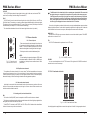
CLIP-LED
The CLIP LED lights up when the input signal is driver too high. In this case, turn down the TRIM
control and, if necessary, check the setting of the channel EQ.
SOLO
The SOLO switch is used to route the channel signal to the solo bus (Solo In Place) or to the PFL bus
(Pre Fader Listen). This enables you to monitor a channel signal without affecting the main output signal.
The signal you hear is sourced either before (PFL, mono) or after (solo, stereo) both the pan control and
the channel fader (see chapter 2.3.6 “Level meters and monitoring”).
The channel fader determines the level of the channel signal in the main mix (or submix).
MONO
2.2 Stereo channels
L
2.2.1 Channel inputs
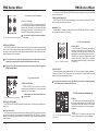
Each stereo channel has two balanced line level input on
1/4" connectors for left and right channels. If only the connector
marked “L” is used, the channel operates in mono. Stereo
channels are designed to handle typical line level signals.
BAL
OR
UNBAL
R
The PAN control in the channel strip offers a constant power characteristic. This means that
the signal is always at a constant level, irrespective of its position in the stereo panorama.
If the PAN control is moved fully left or right from center, the level increases by 4 dB in that
channel. This signal is not louder. For this reason, with the solo function activated (Solo In
Place), audio signals from the channels with PAN controls that have not be moved fully to
the left or right are displayed at a lower volume that in the PFL function.
Also a rule, solo signals are monitored via the control room output and headphones connector and are
displayed by the level meters. If a also switch is pressed, the signals from the tape input, Alt 3-4 and main
mix are blocked from the control room outputs, the headphone connector and the level meter.
MAIN SOLO
The MAIN SOLO LED lights up as soon as a channel or aux send solo switch is pressed. The MODE
switch also has to be set at “solo”.
PFL
The PFL LED indicates that the peak metre is set to PFL mode.
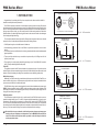
Both input can also be used with unbalanced jacks.
Fig. 2.5: Stereo channel
inputs and LEVEL switch
LEVEL
For level matching, the stereo inputs feature a LEVEL switch
which selects between +4 dBu and -10 dBV. At -10dBV (homerecording level), the input is more sensitive than at +4 dBu
(studio level).
2.2.2 Equalizer stereo channels
The equalizer of the stereo channel is, of course, stereo. The filter characteristics and crossover
frequencies are the same as those of the mono channels. A stereo equalizer is always preferable
to mono equalizers if frequency correction of a stereo signal is needed. There is often a discrepancy
between the settings of the left and the right channels when using separate equalizers.
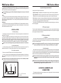
PHONES
Fig. 2.12: PHONES connector
PHONES
You can connect headphone to this 1/4" TRS connector. The signal on the PHONES connection is
sourced from the control room output.
2.3.7 Alt 3-4 and main mix fader
3
4
L
R
10
10
10
10
0
0
0
0
10
10
10
10
15
15
15
15
20
20
20
20
25
25
25
25
30
30
30
30
40
60
40
60
40
60
40
60
8
LINE IN 7/8
8
LEVEL
+4
-10
2.2.4 routing switch, solo and channel fader
BAL
The function of the BAL(ANCE) control corresponds to the PAN control in the mono channels.
The balance control determines the relative proportion between the left and right input signals before
both signals are routed to the main stereo mix bus.
The MUTE/ALT 3-4 switch, the MUTE-LED, the CLP-LED, the SOLO switch and the channel fader
function in the same way as the mono channels.
6
8
In principle, the aux sends of the stereo channels function in just the same way as those of the mono
channels. As aux send paths are always mono, the signal on a stereo channel is first summed to mono
before it reaches it reaches the aux bus.
8
2.2.3 Aux sends stereo channels
ALT 3-4
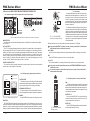
MAIN MIX
Fig. 2.13: Alt 3-4 and main mix fader
Use the high-precision quality faders to control the output level of the Alt 3-4 subgroup and main mix.
11