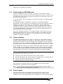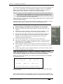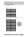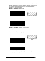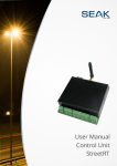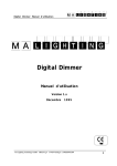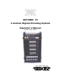
1
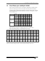
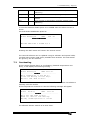
ART2000 T4
4 module Digital Dimming System
Operator’s Manual
software version OS3R1
Stock number 8200-0152
*8200-0152*
Useful Avolites phone numbers:Avolites England
Sales and service*
Service out of hours*
(+44) (0) 20 8965 8522
(+44) (0) 831 17 8888
Fax
(+44) (0) 20 8965 0290
Email
art (at) avolites.com
Website
http://www.avolites.com
Distribution of Avolites products in USA:Avolites America
Sales and service*
(+1) 423 938 2057
Fax
(+1) 423 938 2059
*Before contacting Avolites for service enquiry please ensure that you have the
product serial number and the Software version (shown at switch on).
The latest version of this manual (MS Word 2000 & PDF ) and ART2000
Software can be downloaded from the Internet.
The small print :
No Liability for Consequential Damages
Avolites has a policy of continuous product and documentation improvement. As such
the detail within this manual may not match the operation of the ART2000.
In no event shall Avolites be liable for any direct, indirect, special, incidental, or
consequential damages or loss whatsoever (including, without limitation, damages for
loss of profits, business interruption, or other pecuniary loss) arising out of the use or
inability to use the ART2000 even if Avolites Ltd. has been advised of the possibility of
such damages. Because some jurisdictions do not allow the exclusion or limitation of
liability for consequential or incidental damages, the above limitation may not apply to
you.
Reprint and revision history:
First produced March 2000 by Tim Mitchell, Sabre Technology Ltd Tel: 01482 831031
ELDC Option Added November 2000 By J.B.Toby, Avolites Ltd
Updated for OS3 release, ELDC Portion and added tips March 2001 By J.B.Toby,
Avolites Ltd
Updated for OS3R1 release, various additions By J.B.Toby, Avolites Ltd
A2K-T4-V2.2.doc 02/05/2002 14:44
C O N T E N T S
1.
THE ART2000 DIGITAL DIMMING SYSTEM
4
2.
FEATURES OF THE ART2000
6
3.
INSTALLING THE ART2000
8
4.
SETTING USER OPTIONS
13
5.
ELDC OPTION
22
6.
ONE PHASE PER MULTIPIN OUTLET
23
7.
TROUBLESHOOTING
24
8.
INTRODUCTION TO DMX
27
9.
SYSTEM SPECIFICATION
29
10. CONNECTOR PINOUTS
30
11. GLOSSARY OF TECHNICAL TERMS
32
12. INDEX
34
A2K-T4-V2.2.doc 02/05/2002 14:44
Page 4 - 1. The ART2000 digital dimming system
INTRODUCTION
1.
The ART2000 digital dimming system
This manual is designed to help you get the most out of your Avolites
ART2000 digital dimming system. Even if you hate reading manuals, read
this section because the next couple of pages contain some important
safety information which you should be aware of.
At the end of the manual there is a quick summary of how the DMX control
system works, a Glossary explaining some of the technical terms used in
the ma nual, and an Index which can be used to find what you need in the
manual.
1.1
What it does
The ART2000 system provides a complete solution to Dimming and Moving
Light Power distribution. You no longer need to have separate mains
distribution making set up times faster and reducing the number of
individual components needed to put a show together.
The ART2000 controls up to 48 individual channels. Four modules of a
maximum of 12 channels can be plugged in. The following module types are
currently available:
•
12 channel 16Amp dimming module
•
6 channel 32Amp dimming module
•
3 channel 63Amp dimming module
•
12 channel 16amp distribution module for powering moving lights
•
12 channel 16A Relay module, to switch on/off mains under DMX
control.
Modules of the same channel count can be freely interchanged, and the
rack can be easily configured 'per job' as required.
When loaded with 16A modules the system can be fitted with a patch bay
and up to 20 Multipin outlet connectors which ensure that cabling will be as
simple and reliable as possible.. Each channel of each multipin outlet
connector can be patched to any dimmer output using the hot-patch. The
hot-patch has a lamp test indicator making faults easy to find when a
single dimmer channel powers more than one light fixture. Alternatively
direct outputs are available if a patch is not needed
The 'Load Check' indicators for each dimmer module or relay module channel
give a sure indication that a load is present and the test faders on each
dimmer channel or relay channel allow you to quickly check what’s
connected without having the use of a console.
The design incorporates full monitoring and status feedback via the backlit
LCD display. For simple events you can operate without a console by
setting up a dimmer state on the test faders, or you can record 12 internal
memories for replaying a simple show.
Other features include full DMX patch and merge (2 DMX lines), dimmer
curve and output limit selection per channel, power OK indicators, optional
volt and amp metering and optional RCB or ELDC protection.
A2K-T4-V2.2.doc 02/05/2002 14:44
1. The ART2000 digital dimming system - Page 5
1.2
Important safety information
This system uses 3-phase power and can be a serious hazard to
health. This manual is however not a safety manual.
The system should be installed and operated only by a competent person.
When installing you should check local regulations regarding the separation
of lighting fixtures on different phases (see also section 6 One Phase per
multipin Outlet). If you are in any doubt as to the safe installation of the
system you should employ the services of a qualified electrical contractor.
Do not operate the system with any dimmer modules missing because this
makes live parts accessible.
Blanking plates are available from avolites to allow modules to be removed
and the rack used. If you do want to use the system with a module
removed fit the blanking plate (Avolites part number 17-80-0129)
If Cam-loke loop-out terminals are fitted, ensure that cables or covers are
fitted to the loop-out terminals before turning on the power, as live parts
are otherwise exposed.
Before turning on the ART2000 rack, ensure that the neon power
connection lights on the control panel are correctly illuminated. These lights
will indicate most connection errors. The system may be damaged if it is
turned on with the power feed connected incorrectly.
1.3
Quick start instructions
When connecting the power feed to the system, ensure EARTH is
connected first, then NEUTRAL, then the PHASE conductors. The system
requires a 3 phase (TN-S) mains supply.
Ensure that the Bay and utility breakers are turned off and the optional RCD
breakers are turned on before you turn on the power feed.
Turn on the dimmer feed and check that the “Connection” neons are
correctly illuminated (top 5 on, bottom 2 off). Check that the voltage is
what you expect using the voltmeter. If not OK, correct the fault before
going any further.
Power up the control module by turning the rotary switch below the
Connection neons to R, Y or B to select the phase you want to feed the
electronics from (normally phase R).
You can now turn on the Bay and Utility breakers and use the ART2000
system.
To turn the system off, reverse the above procedure.
It is preferable not to use the RCB as an ON/OFF switch, as arcing may
reduce the RCB’s protecting ability.
A2K-T4-V2.2.doc 02/05/2002 14:44
Page 6 - 2. Features of the ART2000
2.
Features of the ART2000
This chapter gives a quick rundown on what each part of the ART2000 rack
does. If you are new to the system, read this!
Some Parts described in this manual may not be
on the system before you, this is because the
ART2000 system can be supplied from the
factory with various different options.
output connectors
At the rear of the unit, near the bottom of the
rack, are the power input connections. These
can be either Cam-loke , Powerloke ,BACe,
Cee 63 or Cee 125A type connectors. Loop
output connectors may also be fitted.
Note: When connecting power to the ART2000,
always connect the EARTH first, then
the NEUTRAL, then the PHASE
conductors.
If Cam-loke loop-out connectors are fitted,
ensure that either covers or connectors are
fitted before turning on the power, as these
connectors otherwise have exposed live
terminals.
2.1
Utility power panel
Utility panel
Power input
Above the power input is the utility power panel. This may be fitted with
variety of single phase connectors and optional 32A 3-phase connectors.
The utility power is for feeding motors and other devices needing static
power. The circuit breakers for the utility power panel are on the front of
the rack. The 32A 3-phase connector shares the 32A breaker with the
normal 3x 16A utility outputs.
2.2
Output connectors
The rear panel mainly houses the output connectors. Depending on the
option selected these can be either multipin connectors like the Socapexe
and the Hartinge connector or single phase direct outlets like the Cee 16A
or Cee 32A. These connectors link the ART2000 rack to the load which you
want to control.
In both cases it is best to connect these without the channel being
energized as this reduces arcing and prolongs the life of connectors
A2K-T4-V2.2.doc 02/05/2002 14:44
2. Features of the ART2000 - Page 7
2.3
The hot-patch panel
On top of the rack is the optional hot-patch panel. This allows you to
decide how the 48 dimmer channels are connected to the 120 output
circuits which are available on the multipin connectors. The front half of
the panel has the outputs of the modules. Module A has 4 outlets per
channel, and modules B, C and D have 2 outlets per channel.
The hotpatch is normally wired in parallel, thus each socket will have live
and neutral connected (220V). The optional series patch is labelled clearly
to be series (110V)
For the occasional 110V lamp Avolites has a custom Wielande series lead,
part number 03-13-0040
The rear half of the panel has 20 sets of six connectors, one set for each
of the multipin outlets on the rear of the rack.
At the very front of the hot-patch panel is a lamp test socket. This allows
you to test the continuity of any circuit. There is also a desk lamp socket
to allow a gooseneck lamp to be fitted so you can see what you are
patching.
2.4
Main circuit breakers
On the front of the rack, down at the
bottom, there is a 3-phase circuit
breaker for each module, and one for
the utility power. Above the circuit
breakers may be fitted an RCB for each
module. There are also three individual
circuit breakers for the utility power
sockets.
2.5
Hot patch
panel
Control
module
Power modules
The main part of the rack is taken up
with the 4 power modules. These are
interchangeable modules, and the
available types are:
• 12x16A Dimmer module: Each
channel has a 16A C-type circuit
breaker, a control knob and a “load
present” indicator light per channel.
The indicator lights when a load is
connected to the channel, and the
channel is turned off. The control
knob allows manual control of the
channel, if the local control option is
turned on.
Power modules
• 6x32A Dimmer module: Each
channel has a 32A C-type circuit
breaker, and the same control and
indicator features as the above 12 channel dimmer module.
Circuit
breakers &
RCBs
• 3x63A Dimmer module Each channel has a 63A C-type circuit breaker,
and the same control and indicator features as the above 12 channel
A2K-T4-V2.2.doc 02/05/2002 14:44
Page 8 - 3. Installing the ART2000
dimmer module.
• 12x16A Breaker module: Mains distribution modules provide static
power, which can be routed through the hot-patch bay and down the
multicore cables, usually used to power intelligent lighting. The module
has 12 channels of mains power, which can be manually switched using
the front circuit breakers.
Note: If the mains distribution module is fitted as module B, C or D then 24
static power outputs are available on the hot-patch panel. If it is
fitted as module A then 48 static power outputs are available.
• 12x16A Contactor module: Relay modules are like mains distribution
modules but each channel can be switched on/off by DMX control. These
modules are useful if large numbers of ballasts or other special lighting
effects need to be controlled. The relay module has “load present”
indicators and control knob allowing manual control of the channel.
• Blank panel: If a bay is to be left empty fit a blanking panel to balance
the air flow inside the dimmer and prevent live parts to be exposed
Dimmer Channel Mapping
The ART2000 system allocates dimmer channels depending on the module
type fitted to the rack up to a maximum of 48 dimmer channels.
Therefore a two bay frame fitted with two 6 channel modules will use
dimmer channel 1-6 and 7-12, and the same frame fitted with 12 channel
modules will allocated channels 1-12 for the first module and 13-24 for the
next module. In the case of a breaker module preceding a dimmer module in
the rack the dimmer channel 1 will start at the first available dimmer
channel.
Module Type
2.6
Allocated channels
12 channel 16A dimmer
12
6 channel 32A dimmer
6
3 channel 63A dimmer
3
12 channel 16A contactor
12
12 channel 16A breaker
0
No Bay fitted (blanking plate)
0
Control module
At the top of the rack front is the control module. This allows you to set up
how the dimmers will work. There are also voltage and optional current
meters, with phase selector switches, and neon indicators to show if the
power is connected correctly.
The voltmeter switch allows you to measure the phase-neutral and phasephase voltages. A rotary switch below the test neons allows you to select
which phase the electronics is powered from.
The “Display contrast” control allows you to adjust the darkness of the
display.
The “Reset” button allows you to reset the system using a small pointed
implement.
3.
Installing the ART2000
This chapter contains details of how to install the ART2000 rack, either for
A2K-T4-V2.2.doc 02/05/2002 14:44
3. Installing the ART2000 - Page 9
temporary or permanent operation.
3.1
Positioning the ART2000 rack
Choose a location for the rack which is as near to the power feed as
possible and allows access to the front and back of the rack. Consider how
the cables will run in from the power feed and out to the lights, and try to
avoid crossing walkways.
If you are unsure about the safety you should contacts a competent body
to advice you.
The ART2000 system is designed to operate in a maximum ambient
temperature of 40°C and can run continuously when fully loaded at 16A per
channel. The rack is fan-cooled, you must ensure there is adequate
ventilation available - if the system is running in a closed room, consider
providing external ventilation to the room (see Specifications on page 29
for cooling information). The system may shut dimmer modules down if it
cannot release the heat generated.
If you are using the system on an outdoor stage, ensure that the rack is
situated somewhere dry and clear of the ground. If you shelter the rack
with tarpaulins make sure that you do not obstruct the air vents. Black
tarpaulin is general unsuitable.
3.2
Power modules
The ART2000 system has four “bays”, in which you can fit either dimmer
modules, power distribution modules or relay switch modules. The modules
need to be of the same channel capacity (all 12 channel or all 6 channel
modules). If you have a selection of ART2000 modules and need to change
the configuration of the rack by swapping modules, this is the time to do it.
Power distribution modules are used to feed static power down the multipin
outlet, usually to run intelligent lighting. If you do not require this facility
you can replace power distribution modules with dimmer modules and have
more dimmers in the rack (if you have spare dimmer modules available).
3.2.1
Changing power modules
è
Disconnect the mains to the rack
è
Unscrew the 2 M6 screws at the front of the module
è
Use the handles in the front to pull it out (take care, it is quite heavy)
è
Fit the new module by guiding it into the slides
è
Push it home and refit the screws.
Only operate the system when all the modules are screwed in place,
otherwise the connectors may be damaged.
Note: Avoid changing modules when powered because this may cause
arcing, which will damage the connectors.
3.3
Power supply
You need to provide a three phase and neutral power supply to the
ART2000 (TN-S) which is capable of delivering the amount of power
required to run all the lights which are connected to it. If the power supply
A2K-T4-V2.2.doc 02/05/2002 14:44
Page 10 - 3. Installing the ART2000
is under-rated it may trip during your show if you turn too many lights on at
once. This is obviously not a good thing to happen. Also, an overloaded
mains supply can suffer from a distorted waveform which can make it
difficult for the ART system to control your lights smoothly.
Warning: Never use mains supplied with “reduced neutral” cable sizes, as
dimmers inherently dump large currents in the neutral connection.
These kind of mains supplies are sometimes called “industrial “ and
are not suitable for dimmer applications.
When ordering or specifying a mains supply state that it is for “phase angle
controlled light dimming”
The frequency of the mains is automatically tracked by the system, which
makes the ART system suitable for use on local generator sets.
3.3.1
Connecting the power supply
è
Ensure the bay and utility circuit breakers are turned off
è
Before handling the power cables ensure yourself that they are
“dead”
è
Connect the power supply to the Power Input terminals on the
rear of the rack (earth first, then neutral, then phases)
è
If loop out terminals are fitted you can use these to connect a
second rack, provided you do not overload the supply. (Both
Powerloek and Camloke have a 400A limit).Cover unused
Camloke loop out connectors
è
Turn on the power feed - do not turn on the racks yet.
è
Check the connection neons on the front panel. The top 5 neons
should all be lit. The bottom 2 should not be lit. Also check any
other racks you have linked in.
è
Check that the voltage of the supply is what you expected, using
the voltmeter (the voltmeter and neons are fed through the control
fuses)
è
If all is OK, power up the control module by turning the rotary switch
below the neons to the red phase.
If the connection neons or voltmeter indicate a problem, DO NOT
TURN THE RACK ON until you have corrected the problem, or you may
cause serious damage to the rack and connected equipment.
When you turn on the power, the control module will start up and display
the following screen:
Line A 001 Dmx ok
Line B 001 No Dmx
Status Running OK
Mode
Test Off
-----------------------------------------OS 3.0R1
UCode 1.0
PDE 1.0/1.2
The ART team wishes you happy dimming
Now you can then power up the system by turning on the bay and utility
circuit breakers.
If the display shows other messages, this may indicate that a problem has
been found. See the Troubleshooting section on page 24 for details of what
A2K-T4-V2.2.doc 02/05/2002 14:44
3. Installing the ART2000 - Page 11
to do.
If you cannot read the display you may need to adjust the display contrast
control at the bottom right hand corner of the display.
Note: The phase selector intended usage is that it allows you to power the
electronics of a different phase in case of a phase failure. There is
normally no need to go to the yellow or blue phase.
3.4
Connections to lights
You connect the lighting rig to the ART2000 either through the multipin
connectors (Socapex or Harting) or through direct outlets on the rear
panel. There are up to 20 multipin connectors, each of which carry 6
channels (Harting-type connectors may carry 8 channels). The optional
hot-patch panel allows you to determine which dimmer channel controls
which output circuit (direct out versions do not have a hot patch).
Do not connect or disconnect the multipin connectors whilst channels are
turned on, as this may cause arcing which will damage the connectors.
Note: Only connect loads through the multipin outlets, direct outlets or
the utility outlets. DO NOT try to power any equipment directly from
the dimmer output patch on the hot-patch panel as the patch
cables do not carry an earth connection.
3.5
Control connection
Two DMX inputs (and linked outputs) are provided, these allow you to use
two consoles (such as a normal “static light” console and a moving light
console), or to have a back-up control link. Normally the system will
combine the two inputs with a highest-takes-precedence rule. It is also
possible to configure the system so that some dimmers are controlled by
one DMX input only (see section 4.5).
If you need to change the DMX start address of the system this is
described in section 4.1.
If you are linking the DMX cable on to other devices, ensure the termination
switches are set to Off. If this is the end of the DMX line, set the
termination switch to On for that DMX line. An indicator light comes on
when the termination is On.
3.6
Patching module channels to lights
If a patch is fitted you need to patch each light to a dimmer by connecting
cables on the hot-patch panel. There are two patch options series (110V)
and parallel (240V). Most patches are parallel and the following text
assumes a parallel patch
At the front of the hot patch panel are the outlets from the modules.
Module A has four outlets per channel, and modules B, C and D have two
outlets per channel.
At the back of the hot patch panel are the plugs which link to the multipin
connectors. There is a plug for each circuit on each connector. The picture
shows module channel 19 (channel 7 on module B) connected to circuit 1
on multipin connector 1.
A2K-T4-V2.2.doc 02/05/2002 14:44
Page 12 - 3. Installing the ART2000
You can check if a circuit is working
by plugging the patch cable into the
lamp test socket rather than a
module outlet. If the circuit is OK
the lamp test light will come on.
You should also see the indicator
lights on the channels come on
when you connect a load to them.
The lamp test is powered by a
PP3/MN1604/6F22 9V battery which
is in the plastic compartment on the
front of the rack. Press the Battery
Test button to check the battery
state. There is also a second
compartment which holds a spare
battery, though if you need it
someone will probably have already stolen it.
A Series patch requires two loads to be connected to work, this as the 2
loads will be wired in series with each other to allow the use of 110V lamps.
The first bay allows two sets of loads to connected (thus four loads are
needed)
3.7
Testing channels using the local control faders
When you are setting up the rig, it is useful to be able to fade up a channel
from the dimmer rack. Each dimmer module or relay module channel on the
ART2000 has a fader to allow you to do this. However, the faders can be
disabled to prevent people playing with them. The display shows “Faders
on” or “Faders off” to tell you what the current setting is.
3.7.1
Using the local faders
è
Press TEST ON to enable the faders
è
Turn the fader on the channel you want to change
è
The fader and the DMX input are combined, whichever is highest has
control
è
Press TEST OFF when you have finished.
The local faders combine with the DMX input using highest-takesprecedence (HTP) rules, in other words if the DMX input is turning the
channel on full, you will not be able to take control using the local fader.
You can also program 12 memories into the ART2000 rack, which is useful in
case of emergency, or for very simple setups where you do not need a
control console. This is described on page 19.
A2K-T4-V2.2.doc 02/05/2002 14:44
4. Setting user options - Page 13
4.
Setting user options
The ART2000 has a simple user interface.
Each function has its own button, shown
on the right, so you don’t get lost in
multiple menus.
This section describes how to configure
the ART2000 rack to your requirements.
4.1
Setting the DMX start address
In normal use, you will just set one start address for all 48 dimmers. Module
channel 1 will operate from the DMX start address you set, and the other
47 channels will follow in a continuous block of channels. This is called
“Rack Patch” mode, because the whole rack is patched in one go.
You can set the DMX start address differently for the two DMX inputs, so
for example channel 1 can be controlled by DMX channel 100 on one
console and DMX channel 300 on the other console. This can be useful if
two consoles are controlling the rig, as sometimes happens if you are using
moving lights with external dimmers to control the lamp , and normal static
lights in the same show.
You can also allocate each channel to an individual DMX control channel.
This is called Channel Patch mode and is described later.
4.1.1
Setting the DMX start address
è
Press the DMX A button to change the start address for DMX line A
è
Press the UP or DOWN buttons to change the start address shown on
the screen
è
To change in decades, hold down the X10 button and press Up or
Down
è
Press ENTER to store the new start address.
The display shows
Line A 001
Dmx ok
Line B 001
No Dmx
Status Running ok
Mode
Test Off
-----------------------------------------Change Line A Module start address
Current start address is 001
New start address is 002
Dmx address 000 is not supported
You can set the start address for DMX line B by using the DMX B button in
the same way.
A2K-T4-V2.2.doc 02/05/2002 14:44
Page 14 - 4. Setting user options
4.2
Viewing the dimmer levels
You can view the output levels of the dimmer channels by pressing the
LEVEL button (above the STORE button). The display shows the output
levels as a bank of numbers.
Line A 001
Dmx ok
Line B 001
No Dmx
Status Running ok
Mode
Test Off
------------BAY INPUT LEVEL-------------Chan.
1 2 3 4 5 6 7 8 9 10 11 12
Bay 1 011012013014015016017018019010010010
Bay 2 021022020000000000000000000000000000
Bay 3 000000000000000000000000000000000000
Bay 4
The screen shot above shows a 48 way frame with three 12 channel
dimmer modules fitted.
The module type will determine the way the levels are displayed, where
12 channel dimmer
or contactor module
Bay 1 011012013014015016017018019010010010
6 channel dimmer
Bay 1 011012013014015016
3 channel dimmer
Bay 1 011012013
12 channel breaker
or no module fitted
Bay 1
Pressing the UP / DOWN button will cycle the screen between the following
data sources
4.3
--BAY INPUT LEVEL--
Input to the dimmer without a curve applied
--BAY OUTPUT LEVEL-
Input to the dimmer following the curve
----DMX A LEVEL----
Exclusive DMX Line A data
----DMX B LEVEL----
Exclusive DMX Line B data
----FADER LEVEL----
Exclusive Fader data
Setting the dimmer curve
Each dimmer channel can have its own “Curve”. This sets the relation of
how the dimmer output responds to the control input.
You can either set each dimmer curve separately, or set them all together
to the same curve.
4.3.1
Setting the dimmer curve
è
Press the CURVE button
è
Select the channel you want to modify using the UP / DOWN buttons,
then press ENTER. The centre line (inverted on the display) shows the
current channel
è
Select the curve setting you want for that channel using the UP/DOWN
buttons, then press Enter.
A2K-T4-V2.2.doc 02/05/2002 14:44
4. Setting user options - Page 15
The display looks like this:
Line A 001 Dmx ok
Line B 001 No Dmx
Status Running OK
Mode
Test Off
-----------------------------------------Change dimmer channel curve
dimmer channel 48 curve: Linear Curve
dimmer channel 01 curve: Linear Curve
dimmer channel 02 curve: Linear Curve
The available dimmer curves are:
•
•
•
•
•
•
•
•
•
Linear Curve - linear response with standard tungsten halogen lamps
Relay On >50% - channel turns on full wave, if input above 50%
Relay Off >50% - channel turns off full wave, if input above 50%
OS3R0 linear – previous software version linear curve
Alt.linear – generic linear curve
Square law - square law dimming curve
5% Pre heat - channel stays on at 5%, input scaled over remaining
95% using a linear curve
10% Pre heat - channel stays on at 10%, input scaled over remaining
90% using a linear curve
15% Pre heat - channel stays on at 15%, input scaled over remaining
85% using a linear curve
User curve- direct DMX 255 steps to firing angle, use this curve when
using a curve in the console
You can modify all 48 channels in one go by holding X10 and pressing
CURVE. The following screen display is shown:
Line A 001
Dmx ok
Line B 001 No Dmx
Status Running ok
Mode
Test Off
-----------------------------------------channel Curve setup for all channels
selected Curve is: Linear Curve
press ENTER to change ALL channels
press EXIT to abandon
Use the UP and DOWN buttons to select the desired curve, then press
Enter.
4.4
Limiting the output of a dimmer
Each dimmer channel can have its own “Limit” setting. This allows you to
restrict the maximum output of the dimmer. You might want to do this to
match the intensity of different lamps. The dimmer will scale its output over
the remaining DMX data range.
Tip: The limit function can also be used to “slow down” the fading response
of theatrical lights, which are often not used at full power. You can use
this to match a 500W lamp fade speed to a 650W lamp.
4.4.1
Setting the dimmer limit
A2K-T4-V2.2.doc 02/05/2002 14:44
Page 16 - 4. Setting user options
è
Press the LIMIT button
è
Select the channel you want to set using the UP / DOWN buttons, then
press ENTER.
è
Select the Limit you want for that channel using the UP/DOWN
buttons, then press ENTER.
To modify the limit for all 48 channels in one go, hold X10 and press LIMIT.
The following screen display is shown:
Line A 001
Dmx ok
Line B 001
No Dmx
Status Running ok
Mode
Test Off
-----------------------------------------Channel Limit setup for all channels
selected Limit is: no limit set
press ENTER to change ALL channels
press EXIT to abandon
Use the UP and DOWN buttons to select the desired limit, then press Enter.
4.5
Soft Patch
The ART2000 system allows you to allocate any DMX address to any
dimmer channel on an individual basis. You can also set different allocations
on DMX line A and line B.
It is important to know that the Art2000 will truncate the dimmer channels
depending on the bay requirements. Consider the following set-ups:
Example 1
Bay 1
12x 16A dimmer
Dimmer channel 1-12
Bay 2
12x 16A dimmer
Dimmer channel 13-24
Bay 3
12x breaker
No dimmer channels allocated
Bay 4
12x 16 A dimmer
Dimmer channel 25-36
Example 2
Bay 1
12x 16A dimmer
Dimmer channel 1-12
Bay 2
12x 16A dimmer
Dimmer channel 13-24
Bay 3
12x 16A contactor
Dimmer channel 25-36
Bay 4
12x 16A breaker
No dimmer channels allocated
Example 3:
Bay 1
6x 32A dimmer
Dimmer channel 1-6
Bay 2
6x 32A dimmer
Dimmer channel 7-12
Bay 3
6x 32A dimmer
Dimmer channel 13-18
Bay 4
6x 32A dimmer
Dimmer channel 19-24
The main application of the softpatch is to patch around faults or problems.
You should preferably use the patching facility in your control console to
allocate dimmers to DMX channels, because there is no way of transferring
the patching information from the dimmer rack if you need to change to a
A2K-T4-V2.2.doc 02/05/2002 14:44
4. Setting user options - Page 17
different rack.
When the ART system leaves the factory the soft Patch is pre-loaded with
a patch starting at DMX 001 dimmer channel 1 till DMX 048 dimmer channel
48.This is called a “one-to-one” (1:1) patch. (see also 4.9 Wipe-all
function ) In most cases you may want to start from a different start
address like 200 or 127. You can select a start point for the 1:1 patch
after the patch mode is set to softpatch.
Changing the patch mode
To use the soft Patch, you need to change the mode for DMX line A or B.
The mode can be different for each line.
4.5.1
Turning on the softpatch
è
Hold X10 and press DMX-A or DMX-B. The display will show the SoftPatch screen.
è
Press UP / DOWN to change the NO into Yes, and press ENTER. The
1:1 Patch screen will now appear
è
If you do not want a 1:1 patch to be loaded press EXIT,
è
if you want to load a 1:1 Patch change the NO into Yes using the UP /
DOWN button.
è
Select the start address where the 1:1 patch needs to start from and
press Enter.
Screen shot after X10 and DMX A:
Line A 001
Dmx ok
Line B 001
No Dmx
Status Running ok
Mode
Test Off
-----------------------------------------Do you want to use a softpatch for Line A
yes
Screen shot after ENTER:
Line A 001
Dmx ok
Line B 001 No Dmx
Status Running ok
Mode
Test Off
-----------------------------------------Do you want to start with a 1:1 softpatch?
No
To switch of the soft-patch, repeat the above procedure selecting NO
when asked if a soft-patch is to be used. The soft Patch information is not
lost when you switch off the softpatch.
When a DMX line is in softPatch mode, the top line of the display shows
“Patch” rather than the base DMX address.
A2K-T4-V2.2.doc 02/05/2002 14:44
Page 18 - 4. Setting user options
If you need to allocate an individual dimmer channel to a different DMX
address you do the following:
4.5.2
Patching individual dimmer channels
è
Press DMX-A or DMX-B (the Dmx input must be set to softpatch mode)
è
The middle line of the display shows the active dimmer. Press UP /
DOWN to select the dimmer channel you want to change, then press
ENTER
è
Press UP / DOWN to set the DMX address for this dimmer channel,
then press ENTER
è
Repeat for other dimmers, or press EXIT to finish
The display shows
Line A Patch Dmx ok
Dmx B 001
No Dmx
Status Running ok
Mode Test off
-----------------------------------------Dmx A softpatch
Dimmer Channel 48
Dmx address 048
Dimmer Channel 01
Dmx address 001
Dimmer Channel 02
Dmx address 002
4.5.3
“Parking” DMX channels
You can set the DMX address of a channel to 000, this “parks” the dimmer
channel so it is not controlled by that DMX line. This is useful if you want a
dimmer to be controllable from only one of the two DMX lines, or if you
want to disable a dimmer.
4.5.4
Behaviour of “X10 and UP /DOWN “
When scrolling through dimmer channels the X10 and UP or DOWN
combination will jump to the first dimmer channel of the following or
preceding bay. Thus in a frame with four 12 channel modules pressing X10
and UP when selecting dimmer channels will result in the channel jumping
from 01 to 13, 25 and 37.
When changing DMX addresses the X10 and UP or DOWN combination will
jump in decades. Thus start addresses 015 changes into 25, 35 etcetera.
A2K-T4-V2.2.doc 02/05/2002 14:44
4. Setting user options - Page 19
4.5.5
When Dmx data has been interrupted
The ART2000 system can detect the availability and usability of Dmx Data
and will show this in the screen
Line A Patch Dmx ok
Dmx B 001
No Dmx
Status Running ok
Mode Test off
------------------------------------------
•
“Dmx ok “ indicates Dmx data which can be used (Line A in above
screen shot)
•
“No Dmx” indicated either no dmx connected or bad Dmx (Line B in
above screen shot)
The ART2000 will retain the last received DMX data if a single Dmx Data
stream is interrupted (this in accordance with DMX 512 1990).
You can clear this data by pressing X10 and TEST OFF and all the channels
held at a level by the interrupted Dmx data will fade to off.
When two data streams are present and one is interrupted the ART2000 will
fade out the “locked” data from the interrupted Dmx stream after 5
seconds and in 5 seconds. This will allow you to regain control over
channels held at a level by the interrupted Dmx Stream.
4.6
Storing dimmer level memories
The ART2000 system can store 12 memories internally. A memory contains
the state of all the 48 channels. This can be useful to keep the show going
if the control console stops working, or if you have a very simple static
set-up which does not require a control console.
If you have multiple racks of Avolites ART dimmers (2000, 4000 or 6000),
you can instruct all connected ART systems to store a “Global” memory.
Once you have stored memories, you can play back these memories from
one control module, allowing you access to all the channels on all the racks
using the controls on the first rack. If you are planning on doing this, the
first rack in the DMX line will be the Master rack, and all the others will be
Slaves. The Master rack will use the DMX-A line to command the
downstream racks to save or play back the memory, and so it is best if only
ART systems are connected to the DMX line downstream from the Master,
since other systems may interfere with memory replay or recording.
4.7
Storing a memory
When you store a memory, it records the current state of all the dimmers
channels. Memories can either be stored as “local” (just the current rack)
or “global” (the current rack will store the memory and instruct all
downstream systems to store as well).This is particularly handy when
storing memories on a multiple dimmer system setup, as you will only have
to store 12 global memories, and not 12 memories for every system.
Use the following procedure to store a memory
4.7.1
Storing a memory
A2K-T4-V2.2.doc 02/05/2002 14:44
Page 20 - 4. Setting user options
è
Press the STORE button
è
Select the Fader location you want to store in using the UP / DOWN
buttons, then press ENTER
è
Select “Local” or “Global” using the UP/DOWN buttons, then press
ENTER.
Screen shot after memory 6 has been entered:
Line A 001
Dmx ok
Line B 001
No Dmx
Status Running ok
Mode Test off
-----------------------------------------Store a memory to a channel fader
Store memory 06 as a local memory
4.8
Replaying a memory
You can replay a memory either locally (just the current rack) or globally
(the current rack and all downstream racks). When you replay a memory
locally, the output is HTP mixed to any DMX levels which may be present.
Use the following procedure to replay a local memory.
4.8.1
Replaying a local memory
è
Press the REPLAY button
è
Turn the fader for the memory you want to replay (faders 1-12 on the
top dimmer module)
è
Press TEST OFF to stop the memory replay.
Note: The faders used to replay a memory are the first 12 faders on Bay 1
If a power distribution module is fitted in Bay A, no memories can be
replayed locally.
If you want to replay a memory globally (i.e. turn on Memory 1 on all the
racks), you need to carry out the following procedure at the Master rack
(the one which is first in the DMX line).
Note: that the DMX line will be interrupted; if you have other equipment
connected after the master dimmer rack they will lose DMX.
4.8.2
Replaying a global memory
è
Press the TRANSMIT MEMORY button on the Master rack
è
Press ENTER to confirm
è
Turn the fader for the memory you want to replay (faders 1-12 on the
top dimmer module). The memory will replay on all racks.
è
To stop transmitting memories, Press the TRANSMIT MEMORY button
on the Master rack
è
Press ENTER to confirm
You can pre-view what channels are stored at what level in a memory
without replaying it
4.8.3
è
Pre-viewing a memory
Press X10 and STORE
A2K-T4-V2.2.doc 02/05/2002 14:44
4. Setting user options - Page 21
è
Use UP and DOWN to cycle trough the 12 memories
Memory pre-view screen shot
Line A 001
Dmx ok
Line B 001
No Dmx
Status Running ok
Mode Test off
----------MEMORY 01 STORED LEVEL---------Chan.
1 2 3 4 5 6 7 8 9 10 11 12
Bay 1 00 00 00 00 00 00 00 00255 00 00 00
Bay 1 00 00 00 00 45 00 00 00 00 00 00 00
Bay 1 00 00 00 00 00 00 09 00 00 00 00 00
Bay 1 00 00 00 00 00 00 00255 00 00 00 00
Pressing the EXIT button will restore the normal screen.
4.9
Wipe-all function
When a rack returns from a job, it is likely that all kinds off user settings
are not set the way you want it. The ART2000 system has a Wipe-all
function, which allows you to reset the system to factory default setting:
4.9.1
Wipe all function
è
Power down the control unit (rotary switch)
è
Press and hold the UP and DOWN button
è
Power up the control unit
è
Wait for the start-up screen to state “happy dimming”
The ART2000 factory settings are:
•
Line A and B are set to “rack patch” mode.
•
Line A and B are set to start address 000.
•
All channels have the linear curve, and no limit applied.
•
All the memories are cleared.
A2K-T4-V2.2.doc 02/05/2002 14:44
Page 22 - 5. ELDC Option
5.
ELDC Option
The ART2000 can be fitted with the ELDC Option, This option allows you to
disable the RCB from tripping the bay breaker during live shoots.
The ELDC system will power up in the “RCB enabled” mode indicated by the
Green switch being lit. After that each bay can be individually disabled
using the ELDC Master control key-switch and the Red disable switch.
The decision to disable the ELDC must be made by a competent body
capable of understanding the safety implications.
The switches will indicate the status of the ELDC system
Green switch lit
ELDC detector active and enabled (Bay is Protected)
Red switch lit
ELDC detector active and disabled (Bay is unprotected)
Green or red
switch not lit
whilst bay
breaker is on
ELDC detector not active, possibly because of a blown ELDC
control fuse .
5.1.1
The ELDC system is not to be used in this
mode the bay is unprotected and unsafe to
use
Disabling an ELDC RCB
è
Turn and hold the ELDC master control key-switch to ”Allow RCB
Disable”
è
Select the bay(s) to be disabled by pressing the Red “RCB disable”
switch, the red switch is now lit
è
Return the ELDC master control key-switch to the centre position
When the Key-switch is in the centre position the key can be removed and
no changes can be made to the Disable selection.
The RCB’s will return to the “enabled mode” after a power down and up
cycle
5.1.2
Resetting the RCB Disable Selection.
è
Turn the Master RCB control key-switch to “Reset RCB disable”, all
green switches are now lit
è
Return the Master RCB control key-switch to the centre position
Note: The ELDC Sensor tripping current is rated at 30mA/30mSec. Power
for the ELDC system is derived from the RED L1 Phase of the
relevant bay breaker and should be 240V ± 10%. An internal fuse
protects the ELCD contact avolites for more details
Warning: Do not use the system without either the Green or Red
indicator lit on used bays
A2K-T4-V2.2.doc 02/05/2002 14:44
6. One Phase per multipin Outlet - Page 23
6.
One Phase per multipin Outlet
Some locations dictate that only one phase is patched per multipin outlet.
Follow the following procedure to hot patch and soft patch the dimmer;
Use Patch leads to connect all Red channels to the first multipin outlet, then the
yellow channels and last the blue channels (i.e. dim Ch. 1 to multipin 1.1, dim
ch 4 to multipin 1.2)
Multpin
1
2
3
4
5
6
Multipin 1
1
4
7
10
13
16
Multipin 2
19
22
25
28
31
34
Multipin 3
37
40
43
46
Multipin 4
2
5
8
11
14
17
Yellow
Multipin 5
20
23
26
29
32
35
Phase
Multipin 6
38
41
44
47
Multipin 7
3
6
9
12
15
18
Multipin 8
21
24
27
30
33
36
Multipin 9
39
42
45
48
Red Phase
Blue Phase
Check that the controller is in patch mode (see 4.5 Soft Patch )
Enter the following patch, on the DMX line to be used:
Dim 1
Dim 2
Dim 3
Dim 4
Dim 5
Dim 6
Dim 7
Dim 8
Dim 9
Dim 10
Dim 11
Dim 12
Dmx 1
Dmx 17
Dmx 33
Dmx 2
Dmx 18
Dmx 34
dmx 3
Dmx 19
Dmx 35
dmx 4
Dmx 20
Dmx 36
Dim 13
Dim 14
Dim 15
Dim 16
Dim 17
Dim 18
Dim 19
Dim 20
Dim 21
Dim 22
Dim 23
Dim 24
Dmx 5
Dmx 21
Dmx 37
dmx 6
Dmx 22
Dmx 38
dmx 7
Dmx 23
Dmx 39
Dmx 8
Dmx 24
Dmx 40
Dim 25
Dim 26
Dim 27
Dim 28
Dim 29
Dim 30
Dim 31
Dim 32
Dim 33
Dim 34
Dim 35
Dim 36
Dmx 9
Dmx25
Dmx 41
Dmx
10
Dmx 26
Dmx 42
Dmx 11
Dmx 27
Dmx 43
Dmx 12
Dmx28
Dmx 44
Dim 37
Dim 38
Dim 39
Dim 40
Dim 41
Dim 42
Dim 43
Dim 44
Dim 45
Dim 46
Dim 47
Dim 48
dmx 13
Dmx
29
Dmx 45
dmx 14
Dmx 30
Dmx46
dmx15
Dmx 31
Dmx47
Dmx 16
Dmx 32
Dmx48
Below is a schematic drawing of the first 7 channels (red phase multipin outlet 1 and 2
A2K-T4-V2.2.doc 02/05/2002 14:44
Page 24 - 7. Troubleshooting
Red
7.
Yellow
Blue
Red
Yellow
Blue
Red
Yellow
Blue
Red
Yellow
Blue
Troubleshooting
The ART2000 system includes many self-testing features. If there is an
internal problem in the system, the control module will usually detect the
problem and tell you about it.
The Status line on the display tells you if the system is happy and healthy,
or if there is something you need to worry about. “Running OK” means that
everything is good. “warning” means that there is a problem, but the
dimmer will carry on working.
7.1
System setup
You can display more information about the system by holding down the
X10 button and pressing the LEVEL button. (Above STORE)
Line A 001
Dmx ok
Line B 001
No Dmx
Status Running ok
Mode Test off
---------------BAY STATUS----------------Found Chan Control Temp OverTemp Run
Bay 1 Yes
12
123
20
No
81
Bay 2 Yes
12
456
21
No
71
Bay 3 No
00
789 -127
No
00
Bay 4 Yes
12
101
21
No
61
This screen shows the status of the bays, where:
Found
Chan
Yes
indicates module detected
No
indicates module not present or undetected
00
No channels detected
12
12 channel dimmer or relay module detected
6
6 channel dimmer module detected
3
3 channel dimmer module detected
A2K-T4-V2.2.doc 02/05/2002 14:44
7. Troubleshooting - Page 25
Control
A run counter inside the dimmer controller (should not be
stationary)
Temp
Temperature of the module (± 3 degrees C)
OverTemp
Indicates the state of the over temperature switch on the
module
Run
A run counter on the Module controller (should not be
stationary)
To see the software details press UP or DOWN when the above screen is
active
X10 and LEVEL SCREEN the press UP
Line A 001
Dmx ok
Line B 001
No Dmx
Status Running ok
Mode
Test off
------------SOFTWARE VERSION--------------
ART OS3.0R0 Ucode 1.0 PDE1.0/1.2
Pressing the EXIT button will restore the normal screen.
The internal software can be updated using PC software and special cable,
(Avolites part number 1808-0016) available from Avolites. Full instructions
are given by the PC software.
7.2
Overheating
If the system detects that it is overheating (heatsink temperature over
80°C), it will display the following warning
Line A 001
Dmx ok
Line B 001
No Dmx
Status Running ok
Mode Test off
--------------WARNING-----------------Bay 1 temperature is over 80 C!"
Is the fan working for this bay?"
Bay will shut down at 90 C!"
Ensure that all fan vents are clear and that sufficient air flow is available to
naturally cool the module.
If the temperature continues to rise the following message will appear
Line A 001
Dmx ok
Line B 001
No Dmx
Status warning
Mode Test off
---------------WARNING------------------Bay 1 has shut down at 90 C!
Check for cause of over-heating!
Bay may resume operation if cooled.
The affected dimmer module is be shut down.
A2K-T4-V2.2.doc 02/05/2002 14:44
Page 26 - 7. Troubleshooting
7.3
Module sensing
If the system detects that it cannot communicate with a module which was
OK at power-up, it displays the following message
Line A 001
Dmx ok
Line B 001
No Dmx
Status warning
Mode Test off
---------------WARNING-------------------Bay 1 not found
A module not being correctly fitted in a bay or being removed whilst
powered up usually causes this.
7.4
Problems with setup changes
If the system cannot write setup changes into its permanent memory it
displays the message below. The system will continue to operate but setup
changes will be lost when it is powered down.
Line A 001
Dmx ok
Line B 001
No Dmx
Status Warning
Mode Test off
---------------WARNING-------------------There was a problem saving data!
Please try again.
Please Contact Avolites for service if this problem occurs.
7.5
Dimmer Engine Control Problems
If the system cannot start-up one or more of the four dimmer engines the
following message will appear
Line A 001
Dmx ok
Line B 001
No Dmx
Status Warning
Mode Test off
---------------WARNING-------------------Bay 1 dimming control stopped!
...control now restarted
The system will restart the dimmer engine within about 10 seconds.
Stopping dimmer engines is generally a sign of bad mains, or bad
connections on the control board
The remaining bays will work as normal and the dimmer can be used
7.6
Software upgrade
Any ART system running OS 2.0R0 or higher software can be upgraded
using a serial cable and a PC.
The Software will be made available free of charge, on the Avolites web
site under “Downloads”, you will also find data on how to make the cable
Alternatively you can buy the cable from Avolites, part number: 1808-0016
A2K-T4-V2.2.doc 02/05/2002 14:44
8. Introduction to DMX - Page 27
7.7
Resolving circuit problems
If a dimmer circuit does not operate as you expect, don’t panic! There are
several possible causes.
Check the lamp: on the hot-patch panel on top of the rack, connect a
cable from the multicore oulet to the lamp test socket and check that the
lamp test light comes on. If not, the lamp or multicore cable is faulty. Try
another lamp or a different cable.
Check the dimmer channel: With all control channels at zero, plug the hot
patch cable from the multicore oulet to the dimmer channel. The neon on
the dimmer channel should come on to indicate a load is present. Press
Test On and fade up the manual fader on the channel. If this does not work
there is a problem with the dimmer channel (check the channel circuit
breaker is turned on!). If you have a spare dimmer module try changing the
module.
Check the control setup: If all the above is OK, then you may have a DMX
control problem. Make sure that the rack is set to the same DMX channel
as the control console. If the display shows that the DMX line you are using
is in Channel Patch mode, make sure the dimmer channel has not been
patched somewhere else or has been “parked”.
If you are experiencing common faults or patterns (such as every 3rd
channel not working) this can indicate a phase supply problem.
You may be able to solve problems by restarting the dimmer rack or
pressing the reset button using a small pointed implement.
C H A P T E R
8.
S E V E N
Introduction to DMX
This section is for those who are put off by dip switches, lights that move
unexpectedly and strange digital control systems that fly down microphone
cables.
8.1
Ordinary lighting
Standard lighting consists of a variety of light bulbs connected to dimmers.
The lights may be anything from par cans to theatrical lanterns, and the
dimmer controls the intensity of the light. A typical controller for standard
lighting has a set of sliders, and each slider controls the intensity of one
dimmer using a low-voltage control signal of 0 to 10 volts. The standard
way to link the sliders to the dimmers is by using a multicore cable with one
core for each dimmer channel.
8.2
The problem with big lighting rigs
Because each dimmer channel needs its own control signal, if you have a
large lighting rig, the control cable can end up being huge, with big
expensive connectors. If you are using intelligent lighting, like scans, this
gets even worse, because some of the more complicated fixtures use 20
channels or more per fixture. You soon need a better way of getting the
control signals from the control console to the equipment.
8.3
The DMX control system
Fortunately, there is an easy to use system for controlling intelligent
A2K-T4-V2.2.doc 02/05/2002 14:44
Page 28 - 8. Introduction to DMX
lighting and dimmers with large numbers of channels. It is called DMX-512,
which stands for Digital MultipleX, and it sends up to 512 control signals
down a 2 core or 4 core screened cable. The cable can be simply daisychained from each lighting device to the next - all DMX devices have a
loop-through connector which allows you to link to the next device.
Normally a 5-pin XLR connectors is used and in the case of the ART
system, all 5 pins should be connected.
Control consoles using the DMX system send out the level for channel 1,
followed by the level for channel 2, then 3, then 4 and so on, all the way
up to a maximum of 512 (though not all DMX systems send out all the
channels). It then goes back to channel 1 and goes round again.
All the units connected to the DMX receive all the channels, and you tell
them which channels to respond to by setting the “start address” on each
unit. The computer inside the dimmer or fixture waits for the correct
channels to come up, then reads in the levels for those channels and uses
them to set the dimmer levels or the fixture positions.
8.4
A few cautions about using DMX
DMX is a robust system which normally works very well, provided you keep
to a few simple rules. Here are a few tips for making DMX work well.
•
DMX cabling should be twisted-pair shielded data cable. Microphone
cable is not recommended because it degrades the signal, especially on
long runs.
•
Always “terminate” the last dimmer or fixture on the DMX line, either
with a special termination plug, or the ART2000 rack has terminator
switches which do this for you. The termination is a 120 ohm resistor
across the DMX data lines which prevents data interference on the line.
It might work without but…
•
Don’t split the DMX cable. Loop it from one unit to the next. If you have
to split it, use a proper active splitter unit like the Avolites Rack splitter
or Avolites truss splitter, part numbers 33-65-1000 (19” mounting, 8
outputs) or 33-65-2000 (truss mounting splitter using a self-fixing
strap, 6 outputs).
•
The DMX specification says you should not have more than 32 unit
loads on one DMX line. Either use several DMX lines (Avolites consoles
usually have more than one) or use a DMX splitter unit. Again, you will
probably get away with using more if you have to, but the DMX signal
will be weaker than it should be.
•
Don’t run your DMX lines near high voltage cables or neon supplies.
They may pick up interference which will stop the system working.
A2K-T4-V2.2.doc 02/05/2002 14:44
9. System specification - Page 29
C H A P T E R
9.
E I G H T
System specification
The figures below give the specification of the standard ART2000 system.
Power Ratings
Minimum
Maximum
Mains input voltage (phase neutral)*
110V/220V
120V/240V
Mains input frequency
42Hz
72Hz
Current drawn per phase
274A
Current per channel
16A/32A/63A
*System is manufactured for either 110V or 240V
Environmental ratings
Minimum
Maximum
Ambient temperature
0°C
40°C
Internal heatsink temperature
70°C
Relative humidity
-
90% noncondensing
Fan cooling airflow (cubic ft/min)
Minimum
Maximum
Normal operation
80 CFM
100 CFM
Maximum load
850 CFM
Physical information
Dimensions (all rack lids fitted)
580 x 1005 x 1180 mm LxDxH
Weight
198Kg (48x16A)
Channel/Phase information
12
channel
module
6
channel
module
3
channel
module
Red phase
1,4,7,10
1,3
1
Yellow phase
2,5,8,11
2,4
2
Blue phase
3,6,9,12
3,5
3
A2K-T4-V2.2.doc 02/05/2002 14:44
Page 30 - 10. Connector pinouts
10. Connector pinouts
The tables below give the wiring of the connectors used on the standard
ART2000 system.
DMX connectors (5 pin XLR)
DMX LINE A
Pin
1
2
3
4
5
DMX LINE B
Pin
1
2
3
4
5
Function
Earth
Data Data +
Line B Data Line B Data +
Function
Earth
Data Data +
(loop through)
(loop through)
Multipin outlet connectors: Various types of connector may be fitted by
Avolites. See previous page for phasing of outputs.
Socapexe 19 pin
Pin
1
2
3
4
5
6
7
8
9
10
11
12
13
14
15
16
17
18
19
A2K-T4-V2.2.doc 02/05/2002 14:44
Function
Live 1
Neutral 1
Live 2
Neutral 2
Live 3
Neutral 3
Live 4
Neutral 4
Live 5
Neutral 5
Live 6
Neutral 6
Earth
Earth
Earth
Earth
Earth
Earth
Earth
10. Connector pinouts - Page 31
Hartinge / Electroflexe: There are 4 different ways that these connectors
can be wired, please consult Avolites if you are unsure as to which
standard is in use on your system.
Hartinge/ Electroflexe (Harting 1-2)
Pin
1
2
3
4
5
6
7
8
9
10
11
12
13
14
15
16
Earth
Function
Live 1
Neutral 1
Live 2
Neutral 2
Live 3
Neutral 3
Live 4
Neutral 4
Live 5
Neutral 5
Live 6
Neutral 6
Earth
Hartinge/ Lectroflexe (Harting 1-2 & extra Earth)
As above, but pins 13-16 connected to earth.
Hartinge/ Lectroflexe (Harting 1-9)
Pin
1
2
3
4
5
6
7
8
9
10
11
12
13
14
15
16
Earth
Function
Live 1
Live 2
Live 3
Live 4
Live 5
Live 6
Neutral
Neutral
Neutral
Neutral
Neutral
Neutral
1
2
3
4
5
6
Earth
Hartinge/ Lectroflexe variant (Harting 1-9 & extra Earth)
as above, but pins 7, 8, 15, 16 are also connected to earth.
A2K-T4-V2.2.doc 02/05/2002 14:44
Page 32 - 11. Glossary of technical terms
11. Glossary of technical terms
ADDRESS
see START ADDRESS
BAY
The ART2000 rack has 2 or 4 bays depending on the
model , each of whic h can hold either a dimmer
module, relay module or power distribution module.
CHANNEL
One circuit of a dimmer/distribution system, which
may be connected to one or more lamps in parallel.
Also used to refer to the slider controlling the dimmer
on the control console and the control value in the
DMX system which links the two.
SOFT PATCH
Patching mode where each dimmer channel can be
assigned to any DMX Address (they do not need to be
in a sequence)
CURVE
How the output of the dimmer corresponds to the
input. Used to correct for non-linear response of some
types of lamp.
DIMMER
Device which allows control over the intensity of a
lighting fixture.
DMX
DMX512(1990) a specification for communication
between control desks and dimmers or fixtures,
Originally for Dimmers it has been adopted as a
control protocol for most lighting systems. It can
carry 512 different slots of 8-bit data.
HOT-PATCH
A plugging system which allows you to connect any
dimmer channel output to any Multicore channel. The
“hot” refers to the patch carrying mains voltage.
HTP
Highest Takes Precedence, a mechanism for
determining the output level of a Channel held in more
than one Playback Channel. The Channel outputting
the Highest value at any given time will always
determine the level of the Channel. Also see LTP.
INTELLIGENT LIGHTING
Generally refers to some type of motorised light or
colour changer. Also called Intelligent Fixture, Device,
Instrument, Moving Light.
MODULE
An electronics pack containing either 12 dimmer
channels or 12 power distribution channels.
MULTICORE
A cable/connector system which can carry multiple
connections. Often used to connect 6 lights to a
Dimmer rack instead of using 6 separate cables.
Sometimes the brand name of the connector is used,
e.g. Socapex or Harting.
PHASES
Mains power is supplied in three different live
conductors, each called a phase. Consult an
electrician for more details.
PREHEAT
If a small voltage is left applied to a lamp when the
channel is turned off, it turns on faster. This
technique is called Preheat.
A2K-T4-V2.2.doc 02/05/2002 14:44
11. Glossary of technical terms - Page 33
RACK PATCH
Patching mode where dimmers are allocated to
sequential DMX control channels
RCB
Residual Current Breaker. Helps to protect the user
against electrocution by detecting an imbalance
between the current leaving the unit down the live
conductor and the current returning down the
neutral, and isolating the supply the current differs by
more than 30mA.
RISE TIME
The time taken for the mains output to rise to full
voltage when the dimmer channel turns on. This
happens 100 times per second and has a large effect
on the amount of interference generated by the
dimmer (longer rise time = less interference). It also
affects the acoustic noise made by a lamp filament.
START ADDRESS
The first DMX channel used by the dimmer or fixture.
Usually a block of channels is used, starting from the
Start Address.
TERMINATION
The end of a DMX run should always be fitted with a
terminating resistor to prevent data problems. The
ART2000 rack has switches to do this.
TN-S
Type of three phase power system with neutral
bonded to earth at the substation, and a separate
earth conductor throughout the system.
A2K-T4-V2.2.doc 02/05/2002 14:44
Page 34 - 12. Index
12. Index
A
address, setting DMX, 13
B
bargraph button, 14
battery for lamp test, 12
bays, for power modules, 9
E
E-mail number, ii
error messages, 24
F
fan cooling, 9
fault messages, 24
Fax number, UK, ii
Fax number, USA, ii
C
Camlok connectors, 5, 6
changing power modules, 9
channel patch mode, 16
channel, setting DMX address,
13
circuit breakers, 7
connecting power to the
system (detail), 10
connecting power to the
system (overview), 6
connection neons, 10
connections to lights, 11
connector wiring, 30
contrast of display, adjusting,
8, 11
control module (overview), 8
current meter, 8
curve of dimmer, 14
D
desk lamp socket, 7
dimmer
setting curve , 14
setting limit , 15
dimmer bays, 9
dimmer modules (overview), 7
display contrast control, 8, 11
distribution module, 8
DMX channel, setting, 13
DMX connector wiring, 30
DMX lines, 28
DMX, introduction to, 27
DMX, parking channels, 18
A2K-T4-V2.2.doc 02/05/2002 14:44
H
Harting connector wiring, 31
hot-patch panel (overview), 7
hot-patch panel, patching
channels, 8, 11
I
installation of the rack, 9
Internet address, ii
L
lamp test socket, 12
lamp test socket (overview), 7
level display, 14
limiting dimmer output, 15
load check indicators, 4
local control faders
enabling , 12
using, 12
local on, local off, 12
M
main circuit breakers, 7
mains distribution modules, 8
mains fault neons, 10
Manual software, ii
memories, internal, 19
module types, 7
multicore connectors, 11
12. Index - Page 35
O
options
setting user options , 13
output level display, 14
overheating fault, 9, 25
P
parking DMX channels, 18
patching channels on hot patch
panel, 8, 11
phase selection switch, 10
Phone numbers, ii
power
connecting to the system
(overview), 6
connection instructions , 10
power input connections, 6
power modules
changing, 9
Powerlok connectors, 6
Sales and service numbers, USA,
ii
Service numbers, UK, ii
setting dimmer curve, 14
setting dimmer limit, 15
setting DMX channel, 13
Socapex connector wiring, 30
software
updating from PC, 24
version number, 24
specification of system, 29
status display, 24
storing memories, 19
system specification, 29
system status display, 24
T
testing dimmer channels, 12
testing lamps, 12
transmit memory button, 20
troubleshooting, 24
turning on channels on
dimmers, 12
Q
U
quick start instructions, 5
R
rack patch mode, 13
relay module, 8
replaying memories, 19
reset button, 8
S
safety information, 4, 5
Sales and service numbers, UK, ii
A2K-T4-V2.2.doc 02/05/2002 14:44
updating software, 24
utility power panel, 6
V
voltage meter, 8
W
Website , ii