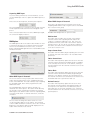
1
Programming Guide and User Manual Model # ADMX ArchiDMX - Self Contained DMX Control Device INS # Contents Introduction6 A Quick Tour of ArchiDMX’s Main Features 6 Stand-Alone Playback . . . . . . . . . . . . . . . . . . . . . . . . . . . . . . . . . . . . . . . . . . . . . . . . . . . . . . . . . . . . . . . . . . . . . . . . . . . . . . . . . . Presets . . . . . . . . . . . . . . . . . . . . . . . . . . . . . . . . . . . . . . . . . . . . . . . . . . . . . . . . . . . . . . . . . . . . . . . . . . . . . . . . . . . . . . . . . . . . . Effects. . . . . . . . . . . . . . . . . . . . . . . . . . . . . . . . . . . . . . . . . . . . . . . . . . . . . . . . . . . . . . . . . . . . . . . . . . . . . . . . . . . . . . . . . . . . . . Buttons . . . . . . . . . . . . . . . . . . . . . . . . . . . . . . . . . . . . . . . . . . . . . . . . . . . . . . . . . . . . . . . . . . . . . . . . . . . . . . . . . . . . . . . . . . . . . Wireless Control . . . . . . . . . . . . . . . . . . . . . . . . . . . . . . . . . . . . . . . . . . . . . . . . . . . . . . . . . . . . . . . . . . . . . . . . . . . . . . . . . . . . . . IR Remote Control. . . . . . . . . . . . . . . . . . . . . . . . . . . . . . . . . . . . . . . . . . . . . . . . . . . . . . . . . . . . . . . . . . . . . . . . . . . . . . . . . . . . . DMX Capture and Backup. . . . . . . . . . . . . . . . . . . . . . . . . . . . . . . . . . . . . . . . . . . . . . . . . . . . . . . . . . . . . . . . . . . . . . . . . . . . . . . Attractive Design. . . . . . . . . . . . . . . . . . . . . . . . . . . . . . . . . . . . . . . . . . . . . . . . . . . . . . . . . . . . . . . . . . . . . . . . . . . . . . . . . . . . . . Easy Installation. . . . . . . . . . . . . . . . . . . . . . . . . . . . . . . . . . . . . . . . . . . . . . . . . . . . . . . . . . . . . . . . . . . . . . . . . . . . . . . . . . . . . . . 6 6 7 7 7 7 7 8 8 Installation8 Architectural. . . . . . . . . . . . . . . . . . . . . . . . . . . . . . . . . . . . . . . . . . . . . . . . . . . . . . . . . . . . . . . . . . . . . . . . . . . . . . . . . . . . . . . . . . 8 Portable Enclosure. . . . . . . . . . . . . . . . . . . . . . . . . . . . . . . . . . . . . . . . . . . . . . . . . . . . . . . . . . . . . . . . . . . . . . . . . . . . . . . . . . . . 10 Hardware Configuration 10 Configuration Display. . . . . . . . . . . . . . . . . . . . . . . . . . . . . . . . . . . . . . . . . . . . . . . . . . . . . . . . . . . . . . . . . . . . . . . . . . . . . . . . . . 10 Dip Switch Settings. . . . . . . . . . . . . . . . . . . . . . . . . . . . . . . . . . . . . . . . . . . . . . . . . . . . . . . . . . . . . . . . . . . . . . . . . . . . . . . . . . . 10 Left Switch Bank. . . . . . . . . . . . . . . . . . . . . . . . . . . . . . . . . . . . . . . . . . . . . . . . . . . . . . . . . . . . . . . . . . . . . . . . . . . . . . . . . . . . . 10 Right Switch Bank. . . . . . . . . . . . . . . . . . . . . . . . . . . . . . . . . . . . . . . . . . . . . . . . . . . . . . . . . . . . . . . . . . . . . . . . . . . . . . . . . . . . 10 Using ArchiDMX Studio 11 Managing Stations. . . . . . . . . . . . . . . . . . . . . . . . . . . . . . . . . . . . . . . . . . . . . . . . . . . . . . . . . . . . . . . . . . . . . . . . . . . . . . . . . . . . Wireless Stations. . . . . . . . . . . . . . . . . . . . . . . . . . . . . . . . . . . . . . . . . . . . . . . . . . . . . . . . . . . . . . . . . . . . . . . . . . . . . . . . . . . Offline Stations. . . . . . . . . . . . . . . . . . . . . . . . . . . . . . . . . . . . . . . . . . . . . . . . . . . . . . . . . . . . . . . . . . . . . . . . . . . . . . . . . . . . . Copying Station Data. . . . . . . . . . . . . . . . . . . . . . . . . . . . . . . . . . . . . . . . . . . . . . . . . . . . . . . . . . . . . . . . . . . . . . . . . . . . . . . . Remotely Controlling Stations. . . . . . . . . . . . . . . . . . . . . . . . . . . . . . . . . . . . . . . . . . . . . . . . . . . . . . . . . . . . . . . . . . . . . . . . . . . Programming Stations. . . . . . . . . . . . . . . . . . . . . . . . . . . . . . . . . . . . . . . . . . . . . . . . . . . . . . . . . . . . . . . . . . . . . . . . . . . . . . . . . Synchronizing Data With Stations . . . . . . . . . . . . . . . . . . . . . . . . . . . . . . . . . . . . . . . . . . . . . . . . . . . . . . . . . . . . . . . . . . . . . . Saving Show Files . . . . . . . . . . . . . . . . . . . . . . . . . . . . . . . . . . . . . . . . . . . . . . . . . . . . . . . . . . . . . . . . . . . . . . . . . . . . . . . . . . Opening and Importing Show Files. . . . . . . . . . . . . . . . . . . . . . . . . . . . . . . . . . . . . . . . . . . . . . . . . . . . . . . . . . . . . . . . . . . . . General Settings. . . . . . . . . . . . . . . . . . . . . . . . . . . . . . . . . . . . . . . . . . . . . . . . . . . . . . . . . . . . . . . . . . . . . . . . . . . . . . . . . . . . Show Name . . . . . . . . . . . . . . . . . . . . . . . . . . . . . . . . . . . . . . . . . . . . . . . . . . . . . . . . . . . . . . . . . . . . . . . . . . . . . . . . . . . . . Security PIN . . . . . . . . . . . . . . . . . . . . . . . . . . . . . . . . . . . . . . . . . . . . . . . . . . . . . . . . . . . . . . . . . . . . . . . . . . . . . . . . . . . . . Power-On Preset. . . . . . . . . . . . . . . . . . . . . . . . . . . . . . . . . . . . . . . . . . . . . . . . . . . . . . . . . . . . . . . . . . . . . . . . . . . . . . . . . . Enable Grandmaster. . . . . . . . . . . . . . . . . . . . . . . . . . . . . . . . . . . . . . . . . . . . . . . . . . . . . . . . . . . . . . . . . . . . . . . . . . . . . . . Enable Front-Panel Buttons. . . . . . . . . . . . . . . . . . . . . . . . . . . . . . . . . . . . . . . . . . . . . . . . . . . . . . . . . . . . . . . . . . . . . . . . . . Auto Dim Front-Panel . . . . . . . . . . . . . . . . . . . . . . . . . . . . . . . . . . . . . . . . . . . . . . . . . . . . . . . . . . . . . . . . . . . . . . . . . . . . . . Receive Wireless Commands from other Stations. . . . . . . . . . . . . . . . . . . . . . . . . . . . . . . . . . . . . . . . . . . . . . . . . . . . . . . . IR Receiver. . . . . . . . . . . . . . . . . . . . . . . . . . . . . . . . . . . . . . . . . . . . . . . . . . . . . . . . . . . . . . . . . . . . . . . . . . . . . . . . . . . . . . . . Enable User’s Remote . . . . . . . . . . . . . . . . . . . . . . . . . . . . . . . . . . . . . . . . . . . . . . . . . . . . . . . . . . . . . . . . . . . . . . . . . . . . . Number Buttons Function. . . . . . . . . . . . . . . . . . . . . . . . . . . . . . . . . . . . . . . . . . . . . . . . . . . . . . . . . . . . . . . . . . . . . . . . . . . Ten Programmable Function Buttons. . . . . . . . . . . . . . . . . . . . . . . . . . . . . . . . . . . . . . . . . . . . . . . . . . . . . . . . . . . . . . . . . Numeric Entry for Two-Digit Preset Numbers. . . . . . . . . . . . . . . . . . . . . . . . . . . . . . . . . . . . . . . . . . . . . . . . . . . . . . . . . . Up/Down Arrows Function. . . . . . . . . . . . . . . . . . . . . . . . . . . . . . . . . . . . . . . . . . . . . . . . . . . . . . . . . . . . . . . . . . . . . . . . . . Grandmaster Up/Down . . . . . . . . . . . . . . . . . . . . . . . . . . . . . . . . . . . . . . . . . . . . . . . . . . . . . . . . . . . . . . . . . . . . . . . . . . . 11 11 12 12 12 13 14 14 14 14 14 14 15 15 15 15 15 15 15 15 15 15 16 16 2 ArchiDMX - Self Contained DMX Control Devicewww.eaton.com Next/Previous Preset. . . . . . . . . . . . . . . . . . . . . . . . . . . . . . . . . . . . . . . . . . . . . . . . . . . . . . . . . . . . . . . . . . . . . . . . . . . . . None . . . . . . . . . . . . . . . . . . . . . . . . . . . . . . . . . . . . . . . . . . . . . . . . . . . . . . . . . . . . . . . . . . . . . . . . . . . . . . . . . . . . . . . . . Enable Programmer’s Remote . . . . . . . . . . . . . . . . . . . . . . . . . . . . . . . . . . . . . . . . . . . . . . . . . . . . . . . . . . . . . . . . . . . . . . . Allow Editing. . . . . . . . . . . . . . . . . . . . . . . . . . . . . . . . . . . . . . . . . . . . . . . . . . . . . . . . . . . . . . . . . . . . . . . . . . . . . . . . . . . . . Direct Access Preset Codes. . . . . . . . . . . . . . . . . . . . . . . . . . . . . . . . . . . . . . . . . . . . . . . . . . . . . . . . . . . . . . . . . . . . . . . . . Buttons. . . . . . . . . . . . . . . . . . . . . . . . . . . . . . . . . . . . . . . . . . . . . . . . . . . . . . . . . . . . . . . . . . . . . . . . . . . . . . . . . . . . . . . . . . . Button List. . . . . . . . . . . . . . . . . . . . . . . . . . . . . . . . . . . . . . . . . . . . . . . . . . . . . . . . . . . . . . . . . . . . . . . . . . . . . . . . . . . . . . . Name. . . . . . . . . . . . . . . . . . . . . . . . . . . . . . . . . . . . . . . . . . . . . . . . . . . . . . . . . . . . . . . . . . . . . . . . . . . . . . . . . . . . . . . . . . . Function. . . . . . . . . . . . . . . . . . . . . . . . . . . . . . . . . . . . . . . . . . . . . . . . . . . . . . . . . . . . . . . . . . . . . . . . . . . . . . . . . . . . . . . . . None . . . . . . . . . . . . . . . . . . . . . . . . . . . . . . . . . . . . . . . . . . . . . . . . . . . . . . . . . . . . . . . . . . . . . . . . . . . . . . . . . . . . . . . . . Normal. . . . . . . . . . . . . . . . . . . . . . . . . . . . . . . . . . . . . . . . . . . . . . . . . . . . . . . . . . . . . . . . . . . . . . . . . . . . . . . . . . . . . . . . Toggle. . . . . . . . . . . . . . . . . . . . . . . . . . . . . . . . . . . . . . . . . . . . . . . . . . . . . . . . . . . . . . . . . . . . . . . . . . . . . . . . . . . . . . . . . Sequential . . . . . . . . . . . . . . . . . . . . . . . . . . . . . . . . . . . . . . . . . . . . . . . . . . . . . . . . . . . . . . . . . . . . . . . . . . . . . . . . . . . . . Latched . . . . . . . . . . . . . . . . . . . . . . . . . . . . . . . . . . . . . . . . . . . . . . . . . . . . . . . . . . . . . . . . . . . . . . . . . . . . . . . . . . . . . . . Momentary . . . . . . . . . . . . . . . . . . . . . . . . . . . . . . . . . . . . . . . . . . . . . . . . . . . . . . . . . . . . . . . . . . . . . . . . . . . . . . . . . . . . Pile-On Toggle . . . . . . . . . . . . . . . . . . . . . . . . . . . . . . . . . . . . . . . . . . . . . . . . . . . . . . . . . . . . . . . . . . . . . . . . . . . . . . . . . . Preset . . . . . . . . . . . . . . . . . . . . . . . . . . . . . . . . . . . . . . . . . . . . . . . . . . . . . . . . . . . . . . . . . . . . . . . . . . . . . . . . . . . . . . . . . . Operate. . . . . . . . . . . . . . . . . . . . . . . . . . . . . . . . . . . . . . . . . . . . . . . . . . . . . . . . . . . . . . . . . . . . . . . . . . . . . . . . . . . . . . . . . Description . . . . . . . . . . . . . . . . . . . . . . . . . . . . . . . . . . . . . . . . . . . . . . . . . . . . . . . . . . . . . . . . . . . . . . . . . . . . . . . . . . . . . . Presets. . . . . . . . . . . . . . . . . . . . . . . . . . . . . . . . . . . . . . . . . . . . . . . . . . . . . . . . . . . . . . . . . . . . . . . . . . . . . . . . . . . . . . . . . . . Preset List. . . . . . . . . . . . . . . . . . . . . . . . . . . . . . . . . . . . . . . . . . . . . . . . . . . . . . . . . . . . . . . . . . . . . . . . . . . . . . . . . . . . . . . Name. . . . . . . . . . . . . . . . . . . . . . . . . . . . . . . . . . . . . . . . . . . . . . . . . . . . . . . . . . . . . . . . . . . . . . . . . . . . . . . . . . . . . . . . . . . Fade Time . . . . . . . . . . . . . . . . . . . . . . . . . . . . . . . . . . . . . . . . . . . . . . . . . . . . . . . . . . . . . . . . . . . . . . . . . . . . . . . . . . . . . . . Follow Time. . . . . . . . . . . . . . . . . . . . . . . . . . . . . . . . . . . . . . . . . . . . . . . . . . . . . . . . . . . . . . . . . . . . . . . . . . . . . . . . . . . . . . Loop To Preset. . . . . . . . . . . . . . . . . . . . . . . . . . . . . . . . . . . . . . . . . . . . . . . . . . . . . . . . . . . . . . . . . . . . . . . . . . . . . . . . . . . . Effect. . . . . . . . . . . . . . . . . . . . . . . . . . . . . . . . . . . . . . . . . . . . . . . . . . . . . . . . . . . . . . . . . . . . . . . . . . . . . . . . . . . . . . . . . . . Color Cycle. . . . . . . . . . . . . . . . . . . . . . . . . . . . . . . . . . . . . . . . . . . . . . . . . . . . . . . . . . . . . . . . . . . . . . . . . . . . . . . . . . . . . Sparkle. . . . . . . . . . . . . . . . . . . . . . . . . . . . . . . . . . . . . . . . . . . . . . . . . . . . . . . . . . . . . . . . . . . . . . . . . . . . . . . . . . . . . . . . Twinkle. . . . . . . . . . . . . . . . . . . . . . . . . . . . . . . . . . . . . . . . . . . . . . . . . . . . . . . . . . . . . . . . . . . . . . . . . . . . . . . . . . . . . . . . Color Rotate. . . . . . . . . . . . . . . . . . . . . . . . . . . . . . . . . . . . . . . . . . . . . . . . . . . . . . . . . . . . . . . . . . . . . . . . . . . . . . . . . . . . Random Palette. . . . . . . . . . . . . . . . . . . . . . . . . . . . . . . . . . . . . . . . . . . . . . . . . . . . . . . . . . . . . . . . . . . . . . . . . . . . . . . . . Button Appearance. . . . . . . . . . . . . . . . . . . . . . . . . . . . . . . . . . . . . . . . . . . . . . . . . . . . . . . . . . . . . . . . . . . . . . . . . . . . . . . . Levels. . . . . . . . . . . . . . . . . . . . . . . . . . . . . . . . . . . . . . . . . . . . . . . . . . . . . . . . . . . . . . . . . . . . . . . . . . . . . . . . . . . . . . . . . . . . Overview. . . . . . . . . . . . . . . . . . . . . . . . . . . . . . . . . . . . . . . . . . . . . . . . . . . . . . . . . . . . . . . . . . . . . . . . . . . . . . . . . . . . . . . . Preset List. . . . . . . . . . . . . . . . . . . . . . . . . . . . . . . . . . . . . . . . . . . . . . . . . . . . . . . . . . . . . . . . . . . . . . . . . . . . . . . . . . . . . Channel List. . . . . . . . . . . . . . . . . . . . . . . . . . . . . . . . . . . . . . . . . . . . . . . . . . . . . . . . . . . . . . . . . . . . . . . . . . . . . . . . . . . . Level and Patch Editor. . . . . . . . . . . . . . . . . . . . . . . . . . . . . . . . . . . . . . . . . . . . . . . . . . . . . . . . . . . . . . . . . . . . . . . . . . . . DMX Input Capture. . . . . . . . . . . . . . . . . . . . . . . . . . . . . . . . . . . . . . . . . . . . . . . . . . . . . . . . . . . . . . . . . . . . . . . . . . . . . . Using the Patch Editor . . . . . . . . . . . . . . . . . . . . . . . . . . . . . . . . . . . . . . . . . . . . . . . . . . . . . . . . . . . . . . . . . . . . . . . . . . . . . Quick Patch . . . . . . . . . . . . . . . . . . . . . . . . . . . . . . . . . . . . . . . . . . . . . . . . . . . . . . . . . . . . . . . . . . . . . . . . . . . . . . . . . . . . Fixture Control - Create. . . . . . . . . . . . . . . . . . . . . . . . . . . . . . . . . . . . . . . . . . . . . . . . . . . . . . . . . . . . . . . . . . . . . . . . . . . Fixture Control - Copy & Paste . . . . . . . . . . . . . . . . . . . . . . . . . . . . . . . . . . . . . . . . . . . . . . . . . . . . . . . . . . . . . . . . . . . . . Fixture Control - Delete. . . . . . . . . . . . . . . . . . . . . . . . . . . . . . . . . . . . . . . . . . . . . . . . . . . . . . . . . . . . . . . . . . . . . . . . . . . Using the Level Editor. . . . . . . . . . . . . . . . . . . . . . . . . . . . . . . . . . . . . . . . . . . . . . . . . . . . . . . . . . . . . . . . . . . . . . . . . . . . . . Capturing DMX Input . . . . . . . . . . . . . . . . . . . . . . . . . . . . . . . . . . . . . . . . . . . . . . . . . . . . . . . . . . . . . . . . . . . . . . . . . . . . . . DMX Options. . . . . . . . . . . . . . . . . . . . . . . . . . . . . . . . . . . . . . . . . . . . . . . . . . . . . . . . . . . . . . . . . . . . . . . . . . . . . . . . . . . . . . When DMX Input is Detected . . . . . . . . . . . . . . . . . . . . . . . . . . . . . . . . . . . . . . . . . . . . . . . . . . . . . . . . . . . . . . . . . . . . . . . When DMX Output is Restored. . . . . . . . . . . . . . . . . . . . . . . . . . . . . . . . . . . . . . . . . . . . . . . . . . . . . . . . . . . . . . . . . . . . . . ArchiDMX - Self Contained DMX Control Devicewww.eaton.com 16 16 16 16 16 16 16 16 16 16 16 16 16 17 17 17 17 17 17 17 17 17 18 18 18 18 18 19 19 19 19 19 19 19 19 19 20 20 20 20 20 20 20 20 21 21 21 21 3 Hold Last Look. . . . . . . . . . . . . . . . . . . . . . . . . . . . . . . . . . . . . . . . . . . . . . . . . . . . . . . . . . . . . . . . . . . . . . . . . . . . . . . . . . Snap to Current Preset . . . . . . . . . . . . . . . . . . . . . . . . . . . . . . . . . . . . . . . . . . . . . . . . . . . . . . . . . . . . . . . . . . . . . . . . . . . Fade to Current Preset . . . . . . . . . . . . . . . . . . . . . . . . . . . . . . . . . . . . . . . . . . . . . . . . . . . . . . . . . . . . . . . . . . . . . . . . . . . Fade to Black. . . . . . . . . . . . . . . . . . . . . . . . . . . . . . . . . . . . . . . . . . . . . . . . . . . . . . . . . . . . . . . . . . . . . . . . . . . . . . . . . . . Activate Preset (x). . . . . . . . . . . . . . . . . . . . . . . . . . . . . . . . . . . . . . . . . . . . . . . . . . . . . . . . . . . . . . . . . . . . . . . . . . . . . . . Front-Panel Snapshot . . . . . . . . . . . . . . . . . . . . . . . . . . . . . . . . . . . . . . . . . . . . . . . . . . . . . . . . . . . . . . . . . . . . . . . . . . . . . . Default. . . . . . . . . . . . . . . . . . . . . . . . . . . . . . . . . . . . . . . . . . . . . . . . . . . . . . . . . . . . . . . . . . . . . . . . . . . . . . . . . . . . . . . . Snap to Current Preset . . . . . . . . . . . . . . . . . . . . . . . . . . . . . . . . . . . . . . . . . . . . . . . . . . . . . . . . . . . . . . . . . . . . . . . . . . . Fade to Current Preset . . . . . . . . . . . . . . . . . . . . . . . . . . . . . . . . . . . . . . . . . . . . . . . . . . . . . . . . . . . . . . . . . . . . . . . . . . . 21 21 21 21 21 22 22 22 22 Using the Front-Panel Snapshot Feature 22 Recording a Scene . . . . . . . . . . . . . . . . . . . . . . . . . . . . . . . . . . . . . . . . . . . . . . . . . . . . . . . . . . . . . . . . . . . . . . . . . . . . . . . . . . . Changing the Fade Time. . . . . . . . . . . . . . . . . . . . . . . . . . . . . . . . . . . . . . . . . . . . . . . . . . . . . . . . . . . . . . . . . . . . . . . . . . . . . . . Locking the Front-Panel Features . . . . . . . . . . . . . . . . . . . . . . . . . . . . . . . . . . . . . . . . . . . . . . . . . . . . . . . . . . . . . . . . . . . . . . . . Front-Panel Lockout Dip Switch. . . . . . . . . . . . . . . . . . . . . . . . . . . . . . . . . . . . . . . . . . . . . . . . . . . . . . . . . . . . . . . . . . . . . . . . ArchiDMX Studio “DMX Options”. . . . . . . . . . . . . . . . . . . . . . . . . . . . . . . . . . . . . . . . . . . . . . . . . . . . . . . . . . . . . . . . . . . . . . 22 23 23 23 23 Using the Programmer’s Remote 24 Playback Mode . . . . . . . . . . . . . . . . . . . . . . . . . . . . . . . . . . . . . . . . . . . . . . . . . . . . . . . . . . . . . . . . . . . . . . . . . . . . . . . . . . . . . . Activating Presets . . . . . . . . . . . . . . . . . . . . . . . . . . . . . . . . . . . . . . . . . . . . . . . . . . . . . . . . . . . . . . . . . . . . . . . . . . . . . . . . . . Adjusting the Grandmaster . . . . . . . . . . . . . . . . . . . . . . . . . . . . . . . . . . . . . . . . . . . . . . . . . . . . . . . . . . . . . . . . . . . . . . . . . . . Stepping Through Presets . . . . . . . . . . . . . . . . . . . . . . . . . . . . . . . . . . . . . . . . . . . . . . . . . . . . . . . . . . . . . . . . . . . . . . . . . . . . Locking Station Buttons. . . . . . . . . . . . . . . . . . . . . . . . . . . . . . . . . . . . . . . . . . . . . . . . . . . . . . . . . . . . . . . . . . . . . . . . . . . . . . Preset Edit Mode . . . . . . . . . . . . . . . . . . . . . . . . . . . . . . . . . . . . . . . . . . . . . . . . . . . . . . . . . . . . . . . . . . . . . . . . . . . . . . . . . . . . Edit Scene . . . . . . . . . . . . . . . . . . . . . . . . . . . . . . . . . . . . . . . . . . . . . . . . . . . . . . . . . . . . . . . . . . . . . . . . . . . . . . . . . . . . . . . . Edit Fade Time . . . . . . . . . . . . . . . . . . . . . . . . . . . . . . . . . . . . . . . . . . . . . . . . . . . . . . . . . . . . . . . . . . . . . . . . . . . . . . . . . . . . . Edit Follow Time. . . . . . . . . . . . . . . . . . . . . . . . . . . . . . . . . . . . . . . . . . . . . . . . . . . . . . . . . . . . . . . . . . . . . . . . . . . . . . . . . . . . Edit Loop to Preset . . . . . . . . . . . . . . . . . . . . . . . . . . . . . . . . . . . . . . . . . . . . . . . . . . . . . . . . . . . . . . . . . . . . . . . . . . . . . . . . . Edit Repeat Count . . . . . . . . . . . . . . . . . . . . . . . . . . . . . . . . . . . . . . . . . . . . . . . . . . . . . . . . . . . . . . . . . . . . . . . . . . . . . . . . . . Edit LED Indicators. . . . . . . . . . . . . . . . . . . . . . . . . . . . . . . . . . . . . . . . . . . . . . . . . . . . . . . . . . . . . . . . . . . . . . . . . . . . . . . . . . Copy Preset . . . . . . . . . . . . . . . . . . . . . . . . . . . . . . . . . . . . . . . . . . . . . . . . . . . . . . . . . . . . . . . . . . . . . . . . . . . . . . . . . . . . . . . Button Edit Mode . . . . . . . . . . . . . . . . . . . . . . . . . . . . . . . . . . . . . . . . . . . . . . . . . . . . . . . . . . . . . . . . . . . . . . . . . . . . . . . . . . . . Set a Button’s Preset. . . . . . . . . . . . . . . . . . . . . . . . . . . . . . . . . . . . . . . . . . . . . . . . . . . . . . . . . . . . . . . . . . . . . . . . . . . . . . . . Set a Button’s Function . . . . . . . . . . . . . . . . . . . . . . . . . . . . . . . . . . . . . . . . . . . . . . . . . . . . . . . . . . . . . . . . . . . . . . . . . . . . . . DMX Record Mode. . . . . . . . . . . . . . . . . . . . . . . . . . . . . . . . . . . . . . . . . . . . . . . . . . . . . . . . . . . . . . . . . . . . . . . . . . . . . . . . . . . Record a DMX Snapshot. . . . . . . . . . . . . . . . . . . . . . . . . . . . . . . . . . . . . . . . . . . . . . . . . . . . . . . . . . . . . . . . . . . . . . . . . . . . . Station Options. . . . . . . . . . . . . . . . . . . . . . . . . . . . . . . . . . . . . . . . . . . . . . . . . . . . . . . . . . . . . . . . . . . . . . . . . . . . . . . . . . . . . . 900: Startup Preset . . . . . . . . . . . . . . . . . . . . . . . . . . . . . . . . . . . . . . . . . . . . . . . . . . . . . . . . . . . . . . . . . . . . . . . . . . . . . . . . . 901: Wireless PIN. . . . . . . . . . . . . . . . . . . . . . . . . . . . . . . . . . . . . . . . . . . . . . . . . . . . . . . . . . . . . . . . . . . . . . . . . . . . . . . . . . . 902: Grandmaster Enable. . . . . . . . . . . . . . . . . . . . . . . . . . . . . . . . . . . . . . . . . . . . . . . . . . . . . . . . . . . . . . . . . . . . . . . . . . . . . 903: Lock Buttons . . . . . . . . . . . . . . . . . . . . . . . . . . . . . . . . . . . . . . . . . . . . . . . . . . . . . . . . . . . . . . . . . . . . . . . . . . . . . . . . . . 904: Deselect Preset. . . . . . . . . . . . . . . . . . . . . . . . . . . . . . . . . . . . . . . . . . . . . . . . . . . . . . . . . . . . . . . . . . . . . . . . . . . . . . . . 905: DMX Output Restore. . . . . . . . . . . . . . . . . . . . . . . . . . . . . . . . . . . . . . . . . . . . . . . . . . . . . . . . . . . . . . . . . . . . . . . . . . . . 906: Front-Panel Auto-Dim. . . . . . . . . . . . . . . . . . . . . . . . . . . . . . . . . . . . . . . . . . . . . . . . . . . . . . . . . . . . . . . . . . . . . . . . . . . . 961: Display Firmware Version. . . . . . . . . . . . . . . . . . . . . . . . . . . . . . . . . . . . . . . . . . . . . . . . . . . . . . . . . . . . . . . . . . . . . . . . . 962: Enter Self-Test Mode. . . . . . . . . . . . . . . . . . . . . . . . . . . . . . . . . . . . . . . . . . . . . . . . . . . . . . . . . . . . . . . . . . . . . . . . . . . . 981: Recall Built-In Show 1 . . . . . . . . . . . . . . . . . . . . . . . . . . . . . . . . . . . . . . . . . . . . . . . . . . . . . . . . . . . . . . . . . . . . . . . . . . . 982: Recall Built-In Show 2 . . . . . . . . . . . . . . . . . . . . . . . . . . . . . . . . . . . . . . . . . . . . . . . . . . . . . . . . . . . . . . . . . . . . . . . . . . . 989: Erase Memory. . . . . . . . . . . . . . . . . . . . . . . . . . . . . . . . . . . . . . . . . . . . . . . . . . . . . . . . . . . . . . . . . . . . . . . . . . . . . . . . . 25 25 25 25 25 25 26 26 26 27 27 27 27 28 28 28 28 28 29 29 29 29 29 29 29 29 29 29 30 30 30 4 ArchiDMX - Self Contained DMX Control Devicewww.eaton.com Programming Examples 30 Example Example Example Example Example Example Example 31 31 32 32 33 34 35 1: Create a Preset. . . . . . . . . . . . . . . . . . . . . . . . . . . . . . . . . . . . . . . . . . . . . . . . . . . . . . . . . . . . . . . . . . . . . . . . . . . . . 2: Assign a Preset to a Button. . . . . . . . . . . . . . . . . . . . . . . . . . . . . . . . . . . . . . . . . . . . . . . . . . . . . . . . . . . . . . . . . . . 3: Set Timing Parameters for a Preset. . . . . . . . . . . . . . . . . . . . . . . . . . . . . . . . . . . . . . . . . . . . . . . . . . . . . . . . . . . . . 4: Program a Button to Toggle a Preset. . . . . . . . . . . . . . . . . . . . . . . . . . . . . . . . . . . . . . . . . . . . . . . . . . . . . . . . . . . . 5: Create a Loop. . . . . . . . . . . . . . . . . . . . . . . . . . . . . . . . . . . . . . . . . . . . . . . . . . . . . . . . . . . . . . . . . . . . . . . . . . . . . . 6: Change the Indicator Color for a Preset. . . . . . . . . . . . . . . . . . . . . . . . . . . . . . . . . . . . . . . . . . . . . . . . . . . . . . . . . . 7: Program a Button to Activate Multiple Presets . . . . . . . . . . . . . . . . . . . . . . . . . . . . . . . . . . . . . . . . . . . . . . . . . . . . Appendix A: Pairing The Programmer’s Remote 36 Setting the IR Code on the Remote. . . . . . . . . . . . . . . . . . . . . . . . . . . . . . . . . . . . . . . . . . . . . . . . . . . . . . . . . . . . . . . . . . . . . . 36 Setting the IR Code on the Station. . . . . . . . . . . . . . . . . . . . . . . . . . . . . . . . . . . . . . . . . . . . . . . . . . . . . . . . . . . . . . . . . . . . . . . 36 Appendix B: IR Code Specifications 37 ArchiDMX Remote. . . . . . . . . . . . . . . . . . . . . . . . . . . . . . . . . . . . . . . . . . . . . . . . . . . . . . . . . . . . . . . . . . . . . . . . . . . . . . . . . . . . 37 Discrete Preset Activation Codes. . . . . . . . . . . . . . . . . . . . . . . . . . . . . . . . . . . . . . . . . . . . . . . . . . . . . . . . . . . . . . . . . . . . . . . . 38 Appendix C: Determining Firmware Version 39 Viewing the Firmware Version in ArchiDMX Studio . . . . . . . . . . . . . . . . . . . . . . . . . . . . . . . . . . . . . . . . . . . . . . . . . . . . . . . . . . 39 Displaying the Firmware Version on the stations LEDs . . . . . . . . . . . . . . . . . . . . . . . . . . . . . . . . . . . . . . . . . . . . . . . . . . . . . . . 39 Appendix D: Self Test Mode 40 Entering the Self Test Mode. . . . . . . . . . . . . . . . . . . . . . . . . . . . . . . . . . . . . . . . . . . . . . . . . . . . . . . . . . . . . . . . . . . . . . . . . . . . Testing LED Indicators. . . . . . . . . . . . . . . . . . . . . . . . . . . . . . . . . . . . . . . . . . . . . . . . . . . . . . . . . . . . . . . . . . . . . . . . . . . . . . . . . Testing Pushbutton Switches . . . . . . . . . . . . . . . . . . . . . . . . . . . . . . . . . . . . . . . . . . . . . . . . . . . . . . . . . . . . . . . . . . . . . . . . . . . Testing DMX Output. . . . . . . . . . . . . . . . . . . . . . . . . . . . . . . . . . . . . . . . . . . . . . . . . . . . . . . . . . . . . . . . . . . . . . . . . . . . . . . . . . Testing DMX Input. . . . . . . . . . . . . . . . . . . . . . . . . . . . . . . . . . . . . . . . . . . . . . . . . . . . . . . . . . . . . . . . . . . . . . . . . . . . . . . . . . . . Testing the IR Receiver. . . . . . . . . . . . . . . . . . . . . . . . . . . . . . . . . . . . . . . . . . . . . . . . . . . . . . . . . . . . . . . . . . . . . . . . . . . . . . . . Exiting the Self Test Mode . . . . . . . . . . . . . . . . . . . . . . . . . . . . . . . . . . . . . . . . . . . . . . . . . . . . . . . . . . . . . . . . . . . . . . . . . . . . . 40 40 40 40 41 41 41 WARRANTIES AND LIMITATION OF LIABILITY 42 ArchiDMX - Self Contained DMX Control Devicewww.eaton.com 5 Introduction Introduction ArchiDMX is an advanced lighting control playback device for use with all types of DMX based digital lighting fixtures that can fit into a wide variety of commercial, residential and entertainment projects. ArchiDMX offers a wide array of features including: ●● ●● ●● ●● ●● ●● ●● ●● ●● A Quick Tour of ArchiDMX’s Main Features Stand-Alone Playback Preset Scenes - Handles up to 64 presets, each with independent split fade times, follow timers, looping and repeat counts. ArchiDMX is designed to be a completely self-contained DMX controller that can be wall-mounted (like a light switch) or used in its rugged portable enclosure (for rental or temporary installations). ArchiDMX directly outputs (or receives) DMX data so it can be connected directly to one or more lighting fixtures, LED power supplies or digital dimmers. Effects - Each preset may have a dynamic effect applied that can animate the scene. Several parameters can be adjusted for each effect, allowing each scene to be tailored for a wide variety of situations. Add sparkles, twinkles, color cycles, scene rotations and more. ArchiDMXs are programmed by using the free ArchiDMX Studio software (available for both Mac and PC computers) or by using the Programmer’s IR Remote. The Studio software works with ArchiDMXs through the use of a USB RF dongle on the computer. Customizable Buttons - Each button can activate a preset, toggle a scene, start an animated chase, choose from a list of scenes, momentarily flash a preset, activate a pile-on scene and more. Also, each button is backlit by a programmable RGB LED with hundreds of color and blinking options. After the programming of a station is complete, the station operates on its own without needing to be connected to a computer or other processor. Stand-Alone Playback - Outputs DMX data for direct connection to digital dimmers and lighting fixtures. Wireless Control - Stations contain an 2.4 GHz wireless module for triggering buttons between multiple stations, and for communication with a host Mac or PC for show programming and software updates (via a USB dongle). IR Remote Control - An infrared receiver in each station allows the station to be operated by universal remote control or via home/commercial automation systems, or with the optional User’s Remote or Programmer’s Remote for show playback or programming. DMX Capture and Backup - The station can also input DMX for taking DMX snapshots or for allowing the station to operate as an automatic backup for another DMX controller with programmable actions that can be activated when an external DMX controller stops outputting a DMX signal. Attractive Design - ArchiDMX is available in White, Black or Ivory, a decorator wallplate with no visible hardware and custom engraved button caps. Easy Installation - Each station fits into a standard single-gang electrical box and only requires power (12 to 24 VDC, or 16 to 24 VAC) and a DMX data cable. Stations that are operating as a wireless slave to another station only requires power. Presets A “Preset” is the basic building-block of how ArchiDMX controls lighting fixtures. Each preset in ArchiDMX’s internal memory stores several pieces of information, including a scene, several timing parameters, looping information and indicator colors. Each of these pieces of information are called a preset’s properties. Depending on how ArchiDMX will be used, the word “Preset” can be interchanged with either “Scene” or “Cue”. For example, in Entertainment Lighting where users typically use lighting control consoles, they may think of each of Preset as a Cue and the group of all Presets in the station as a Cue List. Here’s a quick description of each of the properties of a preset: ●● ●● ●● 6 Scene - A collection of DMX channel values that make up a single “look” of all of the lighting fixtures connected to the station. For example, a scene might be how the lights look in a home entertainment room while watching a movie. Fade Time - The amount of time it takes to crossfade to a new scene. A fade time of zero causes a scene to appear immediately. Fade times can be chosen from 0.01 seconds all the way up to 24 hours. Optionally, a Split Fade Time can be used, which specifies a different fade time for channels increasing in value and those decreasing in value. Follow Time - The amount of time from the moment that a preset is activated that the station will automatically advance (follow) to the next preset. If the Loop property is set, then the follow will jump to this other preset ArchiDMX - Self Contained DMX Control Devicewww.eaton.com A Quick Tour of ArchiDMX’s Main Features instead. Follow times can be chosen from 0.01 seconds all the way up to 24 hours. ●● ●● ●● ●● Loop - An alternate preset that should follow this preset. Normally, when stepping from one preset to the next (either manually or automatically using Follow times), presets follow each other in numerical order. The Loop parameter can be used to choose a different preset that should come after the current preset. For example, to make a loop from presets 1, 2, 3, 4 and then back to 1, the Loop property of preset 4 should be set to “1”. Repeat - A preset that has a Loop property set can also specify how many times that loop should be repeated by setting this property. A repeat of “0” means that a loop executes indefinitely. A non-zero repeat specifies how many times the loop will be taken before the loop “fallsthrough” to the next preset. Effect - A preset may have an optional effect. This effect is applied to the underlying scene. For example, if a Twinkle effect is chosen, the fixtures in the scene will randomly dip in their intensity, causing a “twinkling” appearance. Each effect has one or more properties that can be ajusted to customize the behavior of the effect. Indicator - Each preset specifies the colors that a station button should illuminate when the preset is assigned to a button. Each preset has separate user-definable colors for “Active” and “Inactive” states as well as a button flashing pattern. ●● ●● ●● Function - This is the primary function of each button. Choices include Normal, Toggle, Sequential, Latched, Momentary, Pile-On and more. Preset - The number of the preset that is activated by the button. In some cases this is the number of the first preset in a group of presets that are activated by the button. Wireless Groups - For wirelessly triggering events on other ArchiDMXs, this property contains a list of the wireless groups that this button transmits it’s function to. Wireless Control ArchiDMX has a 2.4 GHz RF wireless module that can wirelessly communicate with other stations in the same network. This feature allows stations to wirelessly trigger presets and provide feedback between each other. Remote stations can trigger the same presets on a station or different ones - effectively adding to the number of buttons available on a station. Also, a USB dongle can be attached to a Mac or PC computer to remotely program and administer stations using the free ArchiDMX Studio tool, available from the Eaton’s Cooper Controls Business web site. IR Remote Control Effects ArchiDMX contains a powerful effect engine that allows basic static scenes to become dynamic. A variety of effects are available that work on RGB, RGBA, RGBW, RGBAW and single-channel dimmers. Each effect has one or more user-adjustable properties that can customize the effect. For example, an effect’s Rate, Direction, Attack, Decay, Smoothness and more can be changed to produce slowly moving dynamic looks or flashy party scenes. Buttons There are five push buttons on the front of a ArchiDMX. Additionally, there are ten buttons accessible from the User’s IR Remote. ArchiDMX buttons have a wide variety of programmable options that can allow each button to have multiple functions. A button can simply activate a preset, or it can toggle a preset on and off. Additionally, if a preset is part of a loop (or chase) of several presets, the button can activate the loop. A single button can also be set to step through several presets manually with each press, or just to activate a preset momentarily only while the button is held down and more. Each button has several properties that are used to customize the function of each button: ArchiDMX has an infrared remote receiver for activating presets, raising or lowering the grandmaster (the overall brightness of the station), or for programming the station. The available User’s Remote can be used to either activate ten extra preset buttons, or can be configured to allow random access to the station’s 64 presets. The User’s Remote also includes Up & Down Arrow buttons that can either adjust the Grandmaster or advance between presets. The available Programmer’s Remote can be used to recall presets, step from one preset to another, adjust the brightness of the station and program presets, buttons and their properties. Users can teach a universal remote control (popular with home theater setups) to trigger presets in a ArchiDMX or use automation systems (such as Crestron®, AMX®, Vantage®, Control4®. etc.) to send the appropriate IR signals to a ArchiDMX to operate it. DMX Capture and Backup The DMX port on ArchiDMX is bidirectional, allowing it to either send or receive DMX signals. If a ArchiDMX is wired “in-line” with another DMX controller, the station automatically gives the other controller priority over controlling the lighting fixtures. ArchiDMX - Self Contained DMX Control Devicewww.eaton.com 7 Installation This feature allows a ArchiDMX to be used as a backup device. Whenever the other controller stops outputting DMX to the lighting fixtures, the ArchiDMX will begin outputting it’s own data, functioning as a backup to the other controller. ArchiDMX can be programmed to perform one of several actions when the external DMX controller stops outputting DMX, such as automatically activating a preset, continuing to maintain the previous scene being sent by the other controller, or fading out the scene to black. ArchiDMX can also use its DMX input to record (take a snapshot of) the incoming DMX signal into any of the station’s presets. Scenes can be recorded by using the ArchiDMX Studio software, the Programmer’s Remote, or from the station’s front panel. Attractive Design Featuring an attractive front panel that fits a decorator wallplate, ArchiDMX has a minimal design that fits into the decor of most any project. ArchiDMX is available in White, Black or Ivory color schemes with engravable button caps for optional labeling of the button functions. RGB style LED backlighting behind each button can be customized to fit different styles and needs. Installation ArchiDMX is designed to be installed into either a standard single-gang electrical box for Architectural applications or in our portable enclosure for temporary applications. Architectural For architectural installations, ArchiDMX is typically installed “in-wall” by use of a standard single-gang electrical box. ArchiDMX is approximately the same size as a standard residential dimmer switch (see specifications for exact dimensions). ArchiDMX comes with a two-piece decorator wallplate that finishes the installation with a professional look that shows no visible hardware (screws). Multiple gang wallplates are also available. If desired, ArchiDMX can also be mounted in a 3rd party decorator wallplate, however you may need additional mounting screws if using your own wallplate. Power for the station is supplied by a Class 2 transformer that provides between 11 to 28 volts DC (5W minimum), or 14 to 28 volts AC (5VA minimum). Easy Installation If the station is going to be used to output DMX to one or more lighting fixtures, a suitable DMX cable should be run from the station location to the first DMX fixture. Additional DMX fixtures are daisy-chained from the first fixture. ArchiDMX was designed for easy installation. It fits neatly into a standard single-gang electrical box and only requires two connections, one for power and one for DMX. If the station requires a DMX input from another source, a separate DMX cable must be run from the other controller to the station. ArchiDMX’s power requirements are minimal and flexible. The station can be powered by a 11 to 28 volt DC source (5W minimum), or a 14 to 28 volt AC source (5VA minimum). If the station is going to be used only as a wireless slave to another station, no DMX cabling is required. See the figure on the next page for a diagram of the typical wiring connections to ArchiDMX. If the station is connected to lighting fixtures or another DMX controller, then the station requires a DMX cable as well. If the station is being used exclusively as a wireless slave to one or more other stations, then the DMX cabling is not needed. 8 ArchiDMX - Self Contained DMX Control Devicewww.eaton.com Installation Eaton’s Cooper Controls ArchiDMX - Self Contained DMX Control Devicewww.eaton.com 9 Hardware Configuration Portable Enclosure Left Switch Bank The ArchiDMX Portable Enclosure is useful for any application where portability and convenience are required. 1. DMX Pull-Up - Enables a weak pull-up resistor on the DMX Data + line. By default, this switch should be “ON”. This feature can by turned off if some other DMX source on the line has its own pull-up resistor installed. The Portable Enclosure houses a ArchiDMX and provides a DC power input jack for connecting an AC Adaptor as well as both Male and Female 5-pin XLR connections for connection to DMX networks. The station itself is identical to the Architectural version, it just comes packaged as a self-contained, ready to operate kit with convenient jacks pre-wired into the enclosure. Hardware Configuration See the following sections on hardware configurations and dip switch settings for ArchiDMX. Configuration Display When a ArchiDMX is powered-on, it briefly displays a scrolling rainbow pattern on its LEDs. After about one second of this display, all of the LEDs settle on a single color before fading out. The color that the station displays indicates the hardware configuration of the station. The following list shows the possible configurations: ●● ●● 4. DMX Output Only - When turned “On”, this switch disables the bidirectional DMX data port, making ArchiDMX only able to output DMX. This function can be enabled if a special circumstance requires that the station ignore DMX input. Normally, this switch should remain “Off”. 5. Reserved - This switch is currently unused. Leave in the “Off” position. 6. Reserved - This switch is currently unused. Leave in the “Off” position. 7. Reserved - This switch is currently unused. Leave in the “Off” position. All LEDs Green = Wireless Model (SS-205 or SS-305) 8. Reserved - This switch is currently unused. Leave in the “Off” position. Right Switch Bank Nearly all station programming is performed via the optional wireless connection to the ArchiDMX Studio software or through the infrared Programmer’s Remote. Therefore, there are very few hardware settings that can (or need) to be set. ArchiDMX has two banks of eight dip switches (16 switches in total) on the back of the station that are used for setting hardware-level features and to change the default settings for the IR remote. NNote: By default, all switches are set to the “OFF” position, except switches 1 & 2 on the left side are “ON”. The function of each of the switches are described below: ON 10 3. DMX Terminate - Enables a DMX termination resistor on the DMX port. This should only be necessary when the ArchiDMX is at the end of a long line of DMX devices receiving DMX data from another source. Normally, this is not required and should remain “Off”. All LEDs Red = Stand-Alone, Non-Wireless Model (SS105) (please note that this model is no longer available) Dip Switch Settings 2. DMX Pull-Down - Enables a weak pull-down resistor on the DMX Data - line. By default, this switch should be “ON”. This feature can by turned off if some other DMX source on the line has its own pull-down resistor installed. ON 1 2 3 4 5 6 7 8 1 2 3 4 5 6 7 8 Left Switch Bank Right Switch Bank 1. Reserved - This switch is currently unused. Leave in the “Off” position. 2. User’s Remote Lock - When turned “On”, this switch disables the User’s Remote. This setting can also be turned on or off by an option available in ArchiDMX Studio. 3. Front-Panel Memory Lock - When turned “On”, this switch disables the ability for the front-panel to take DMX snapshots or adjust fade times. This setting can also be turned on or off by an option available in ArchiDMX Studio 4. IR Memory Lock - When turned “On”, this switch disables the ability for the IR Programmer’s Remote to edit the memory of the ArchiDMX. This setting can also be turned on or off by an option available in ArchiDMX Studio. 5. IR Direct Preset Codes - When turned “On”, this switch enables the “Direct Preset Codes” feature. This feature enables additional IR codes that directly activate any of the 64 presets in the station. This setting can also ArchiDMX - Self Contained DMX Control Devicewww.eaton.com Using ArchiDMX Studio be turned on or off by an option available in ArchiDMX Studio. 6,7,8. Pair With IR Remote - These three switches choose which remote IR code the station will receive commands from. Use this setting to set specific remote controls to operate only specific stations. This setting can also be chosen by an option available in ArchiDMX Studio. The following table shows which combination of switches correspond to which options: 6 7 8 Pair With Remote OFF OFF OFF Remote Code 1 OFF OFF ON Remote Code 2 OFF ON OFF Remote Code 3 OFF ON ON Remote Code 4 ON OFF OFF Remote Code 5 ON OFF ON Remote Code 6 ON ON OFF All Remotes ON ON ON No Remotes NNote: The screen pictures shown below may appear differently on your computer depending on the operating system and improvements that may have been added to the software since this manual was written. Although most of the screen shots that follow are from the Mac version of the software, it is also available for Windows. Managing Stations When ArchiDMX Studio is opened on your computer, a list view window appears that is used to display all stations that are found wirelessly and stations that have been newly created or loaded from a file. This picture shows the main list view window of ArchiDMX Studio with three wireless stations: NNote: See Appendix A for instructions for changing the IR code used by the Programmer’s Remote. Using ArchiDMX Studio A free application is available from the Eaton’s Cooper Controls Business web site called ArchiDMX Studio that is used to manage and program one or more wireless ArchiDMXs using the ArchiDMX USB RF dongle connected to either a Mac or Windows computer. ArchiDMX Studio can be used for the following actions: ●● ●● ●● ●● ●● ●● Wireless Stations Any stations that are discovered wirelessly by the USB RF Adaptor will appear in the list and include the following information: ●● Find Stations - The application searches for and displays nearby ArchiDMXs. ●● Remotely Control Stations - A remote control window can be opened that allows the user to operate a station remotely. ●● Program Stations - A full programming environment that allows the user to change settings and program buttons and presets all in a graphical format. Offline Editor - Configuration files can be created, edited and saved without requiring a station or USB dongle. Manage Configuration Files - Load and Save station configuration files to and from your Mac or Windows computer. Handle Security - Wireless communications between stations and the computer can be made secure by using PIN numbers. The following chapters describe in detail how to use these various aspects of ArchiDMX Studio. ●● ●● ●● Station - The user-defined name of the station. Show - The name of the show currently running in the station. Serial - The serial number of the station. Version - The version number of the firmware running in the station. Signal - The signal strength of the wireless signal to the station. A colored indicator (Green, Yellow, Red) gives a rough estimate of the overall signal strength. Channel - The Wireless Channel currently being used by the station’s wireless module. If no USB RF Adaptor is connected or no wireless stations are in range, this window will remain empty until a station comes within range or an offline station is created or loaded from a file. NNote: If a station has a PIN number, the user is prevented from uploading or downloading data, or making changes of any kind until the proper PIN number has been entered. ArchiDMX - Self Contained DMX Control Devicewww.eaton.com 11 Using ArchiDMX Studio Offline Stations ●● ArchiDMX Studio can also create new station files or open station files stored on the computer for offline editing. A new offline station can be created by using the File > New menu item. An existing station file can be opened for offline editing by using the File > Open menu item. When an offline station is created or opened, it appears in the main window along with any online stations that have been discovered: ●● ●● Copy and Sync - The data is copied from the dragged station to the station that was the recipient of the drop. Then, the new station’s data is uploaded to the station. Copy Only - The data is copied from the dragged station to the station that was the recipient of the drop. The new data is not uploaded to the station. Cancel - This choice cancels the operation. Remotely Controlling Stations When an online station is selected in the list view, click on the Remote Control button to open the Remote Control window. Offline stations show only the show name in the list view. All other properties in the list view only apply to online stations. Copying Station Data You can Drag & Drop from one station in the list to another to copy the data from one station to another. This small window shows a simulation of the buttons on the chosen ArchiDMX with each button appearing with its “live” button color. Each button can be clicked to wirelessly send a button press to the actual station. Whatever function that would occur with on the station will be triggered remotely by this tool and the resulting change in LEDs will appear in this window. While dragging, the cursor turns to a Hand icon: NNote: If a station has a PIN number, the user is prevented from remotely controlling the station until the proper PIN number has been entered. When one station is dropped onto another, ArchiDMX Studio will ask if you want to perform the copy operation: When copying from one station to another, the user is presented with the following options: 12 ArchiDMX - Self Contained DMX Control Devicewww.eaton.com Using ArchiDMX Studio Programming Stations To change any of the programming in either a connected wireless station or an offline station in the list view, you can either click on the Edit Station button or double-click on the station in the list view. The first time you try to edit a station that’s online, ArchiDMX Studio will first download the configuration data from the station: Once the data is downloaded from the station (or immediately if you’re editing an offline station), the station’s Editor Window will appear: ArchiDMX - Self Contained DMX Control Devicewww.eaton.com 13 Using ArchiDMX Studio The Editor Window is divided into five sections, which can be selected by clicking on the appropriate tab across the top of the window: ●● ●● ●● ●● ●● ●● General Settings - Has settings for the Show Name, PIN, Startup Preset, Button and Grandmaster enabling and for Receiving Wireless Button Commands. IR Receiver - Sets the behavior of the User’s Remote, which Programmer’s Remote the station is paired to and other IR related preferences. Buttons - Sets each of the station’s button properties, such as Name, Function, Preset and Wireless Groups. If you choose to Import, the contents of the file will be loaded into the current station. If you choose to Create a New Station, the file will open as a new station to edit. General Settings The General Settings tab of the station editor window is used to view and/or modify the following station parameters. Presets - Edits each of the station’s preset parameters, such as Name, Fade and Follow Times, Loop, Repeat and Indicator colors. Levels - Edits each preset’s DMX channel levels. DMX Options - Sets various DMX-related options for the station. Synchronizing Data With Stations When editing data on a live station you have an active wireless link to, Sync and Revert buttons appear at the bottom of the editor window. Show Name The Sync button is used to upload the edited data back to the station. The Revert button is used to re-download the data in the station back to the editor window (effectively cancelling any changes that might have been made). The Show Name is used to provide a simple descriptive name for the show. This name is simply for your own convenience. Security PIN Saving Show Files When editing a station, the programming can be saved to a file at any time by using the File > Save menu option. A dialog window will appear that allows you to choose where the file will be saved. Opening and Importing Show Files While using the editor window, if the File > Open menu option is selected, the user will be presented with a choice to either open the file as a new station or to import the data from the file into the station you’re editing. The Station PIN is a security feature. If a station has a PIN number set, then future attempts to upload or download data to the station will require a PIN number before the operation will succeed. Additionally, the Remote Control window and attempts to update a station’s firmware also requires the station’s PIN number to operate. Finally, when two or more stations are programmed to wirelessly share button presses and indicator feedback, they must be using the same PIN number. If two stations have two different PIN numbers, they will not be able to communicate with each other. To remove or disable the PIN number feature, clear this field or set the PIN number to zero (0). 14 ArchiDMX - Self Contained DMX Control Devicewww.eaton.com Using ArchiDMX Studio Power-On Preset When a station is powered on, it can automatically activate a preset. This setting allows any of the 64 available presets in the station to be activated on power-on, or it can activate the same preset that was active before loosing power. By default, “Restore Previous” is chosen, which causes the station to restore the preset that was active before the most recent power loss. Use the popup menu to choose a wireless group to accept commands for. If this station does not need to receive wireless button commands from another station, choose Disabled. IR Receiver The IR Receiver tab of the station editor window is used to view and/or modify the following station parameters. Enable Grandmaster The station’s “Grandmaster” is the overall intensity level of the DMX channel values being output from the station. The Grandmaster can be adjusted from 0 to 100% by using the IR remote control. Normally, the Grandmaster is set to 100%. When a level lower than 100% is chosen, all of the DMX channel values are scaled down by that percentage before being output by the station. If this option is checked, the Grandmaster is functional and a user with either the User’s or Programmer’s remote can raise and lower the brightness level of the station. If this option is not checked, the Grandmaster function is disabled and the station always outputs its presets at 100%. Enable Front-Panel Buttons Enable User’s Remote Is this option is enabled, the User’s Remote can be used to control the station. If disabled, the User’s Remote will have no function. Choose Default to use the option as chosen by the corresponding DIP Switch on the back of the station. If this option is checked, the front-panel buttons on the station are enabled and work normally when pressed. If this option is not checked, the buttons will be locked. When a user presses a locked button on the front of the station, all buttons briefly flash Red and no action is taken by the station. Auto Dim Front-Panel This option causes the LED-illumination behind the front panel buttons to automatically dim when the ambient light surrounding the station gets darker. Three ambient light levels can be chosen (High, Medium and Low). Receive Wireless Commands from other Stations If this station is to receive wireless button commands from another station, this setting is used to specify which wireless group the station should listen to. Number Buttons Function This option selects the behavior of the numeric buttons (0 thru 9) on the User’s Remote. The choices are: Ten Programmable Function Buttons The numeric buttons will behave as ten programmable function buttons that are similar to the front-panel buttons on the station. Use the Buttons Tab in the editor window to set each function and preset as desired for each button on the remote. Numeric Entry for Two-Digit Preset Numbers The numeric buttons will behave as a numeric entry to specify any of the 64 presets in ArchiDMX. When the remote is in this mode, press “1” then “3” to activate preset 13. For presets 0 thru 9, press Zero first (for example, “0” then “7” to activate preset 7). ArchiDMX - Self Contained DMX Control Devicewww.eaton.com 15 Using ArchiDMX Studio Up/Down Arrows Function Buttons The Buttons tab of the station editor window is used to program the functions of each of the station’s buttons: This option selects the behavior of the Up and Down arrow buttons on the User’s Remote. The choices are: Grandmaster Up/Down The arrows will raise and lower the Grandmaster, which is the overall brightness output of the ArchiDMX. Next/Previous Preset The arrows will step to the next or previous preset, in numerical order (or in sequence order if the current preset is part of a loop). None This arrows will have no function. Button List Enable Programmer’s Remote On the left side of this window is a list of the buttons available on this station. Select a button to edit its parameters. The Enable Programmer’s Remote setting is used to choose which Programmer’s Remote should be paired with this station, or if it should be disabled completely. The top section of the button list shows the physical frontpanel buttons on the station. The lower section of the button list shows remote buttons that are available on the User’s IR Remote. The Programmer’s Remote has the ability to be set to one of six different codes. Choose the desired code number with this popup menu. Name Choose Default to use the IR Remote Code as chosen by the DIP Switches on the back of the station. This field is the button’s name. It is for your convenience to provide a descriptive label of what the button’s function may be. Allow Editing If this option is enabled, the Programmer’s Remote can be used to make changes to the program in the station’s memory. Function If this option is disabled, programming with the Programmer’s Remote is disabled. This popup menu selects the button’s primary function. Choose from one of the following options: Choose Default to use the option as chosen by the corresponding DIP Switch on the back of the station. None Direct Access Preset Codes Normal The button will not do anything when pressed. The button will activate its preset. If this option is enabled, the station will receive the special “Direct Access Preset Codes”. These are special IR codes that provide direct access to all 64 presets, each with a single IR code. Choose Default to use the option as chosen by the DIP Switch on the back of the station. Toggle The button will toggle the specified preset on and off. If the button is not active, a press will activate the preset. If the button is active, a press will deactivate the preset. Sequential The button will activate the specified preset when pressed. Then, while the button is active, each additional press will step manually from the current preset to the next preset. 16 ArchiDMX - Self Contained DMX Control Devicewww.eaton.com Using ArchiDMX Studio This function follows the normal sequence of presets on each press, including loops and repeat counts. This function is useful for making a single button able to select one of several different presets. Latched Description The button will activate the specified preset only if the button is not currently active. This function is useful for making sure that a second press of a button doesn’t restart a chase or loop of presets. This field displays a plain-language description of the function of the button, given the currently chosen settings. Momentary The Presets tab of the station editor window is used to set up each of the station’s presets: The button will activate the specified preset only for as long as the button is held down. When the button is released, the station will return to the previous preset that was active. Presets Pile-On Toggle The button will toggle the specified preset on and off as a special “pile-on” overlay on top of the main preset that may also be active. Scenes are output from ArchiDMX by combining the channel levels of the primary preset and all active Pile-On presets by using a “highest-level-takesprecedence” strategy on each DMX channel. More than one Pile-On preset may be active at the same time (offering up to 64 simultaneous Pile-Ons). Preset Preset List This popup menu selects which preset the button function activates. On the left side of this window is a list of the presets available on this station. Select a preset to edit its parameters. Operate When editing the presets for a live station that is wirelessly connected to ArchiDMX Studio, the station will output the DMX scene that is currently selected in the Preset List. This group of controls specify what stations this button operates. Normally, the “This Station” control is selected. When “This Station” is chosen, the button operates the station that the button is physically located. The first item in the list is a special option named “Default Values”. Choose this item to edit the default values for the parameters of each preset. When you want a button to wirelessly send it’s function to another station, chose one or more of the Wireless Groups options. For instance, if you want a button to wirelessly operate another station that’s listening to Group 3, then select “3”. Each preset in the list displays icons on its right side that indicates if that preset specifies its own loop, fade time, follow time or indicator colors instead of using the default values for those properties. When a button is operating a preset on another station, the LED indicator of this button will provide the feedback provided by the remote station. Name Typically, if a button is wirelessly triggering another station, the “This Station” control should not be selected, since you want the button to operate only another station. However, in some cases it may be desirable to have a single button press activate a preset on this station as well as to send the event to other wireless stations. This field is the preset’s name. It is for your convenience to provide a descriptive label on what the preset’s purpose may be. ArchiDMX - Self Contained DMX Control Devicewww.eaton.com 17 Using ArchiDMX Studio Fade Time follow time), presets step in numerical order (such as 1, 2, 3, 4, 5, etc.). A preset’s Fade Time is the amount of time it takes to crossfade to a new scene when this preset is activated. To use the default fade time, the check mark should be not checked. To use a custom fade time for the preset, the check mark should be checked. In the text field, enter the fade time along with choosing the desired units (Seconds, Minutes or Hours) from the popup menu. Any amount of time from 0.01 seconds up to 24 hours may be specified. To cause a preset to appear immediately (with no fade time), specify a fade time of zero (0). ArchiDMX also supports “Split Fade Times”. A Split Fade Time is actually two fade times, one time that is used for channels that are increasing in value and another time used for channels that are decreasing in value. This feature can allow a preset to appear quickly while the previous preset appears to fade out slowly. Other special effects can be created using this technique. To enter a Split Fade Time, put two times in the field, separated by a slash ( “/” ). For example: In this example, when the preset is activated, the channels coming in will fade up in 1.5 seconds, while the channels from the previous preset will fade out in 5 seconds. Follow Time A preset’s Follow Time is the length of time after a preset is activated that the next preset will automatically activate. Use the follow time property to make presets automatically step from one to the next. The Loop To Preset property allows a preset to specify that a different preset should come after this one. For example, to create a short loop that causes presets to execute in the order 1, 2, 3, 4, 1, 2, 3, 4, 1, 2, 3, 4, etc., then preset 4 should have a Loop back to preset 1. When a loop has been selected, a second popup menu appears allowing a number of times that the loop should be repeated to be specified. By default a loop always occurs. You can choose to have a loop only occur from between 1 and 255 times using this menu. For example, if preset 3 loops back to preset 1, and the loop is active for 2 times, then the station will execute the presets in the order 1, 2, 3, 1, 2, 3, 1, 2, 3, 4, 5, etc. Effect Each preset can have an “effect” applied that will dynamically change the colors or intensity of each fixture. Each built-in effect has multiple parameters that can be adjusted to customize the way that the effect animates the scene. By adding a Twinkle, Color Cycle, Rotate or Sparkle to a basic scene, all kinds of dynamic effects can be easily created. For simple effects, like the “Color Cycle” effect shown above, only two parameters are available to adjust, the Direction and Rate. In the text field, enter the follow time along with choosing the desired units (Seconds, Minutes or Hours) from the popup menu. Any amount of time from 0.01 seconds up to 24 hours may be specified. In the example above, the preset will automatically activate the next preset 10 seconds after this preset is activated. Presets can follow each other in a simple sequential manner, or follow times can be combined with the Loop To Preset property to create loops. Loop To Preset Normally, when stepping from preset to preset (either manually with a Sequential button or automatically with a 18 For a more complicated effect, such as the “Twinkle” effect shown above, more parameters are available to adjust, such as Rate, Attack, Decay and Depth. The following list describes the behavior of the available effects: Color Cycle The hue of each color in the scene is rotated around the color wheel, producing a dynamic rainbow effect. ArchiDMX - Self Contained DMX Control Devicewww.eaton.com Using ArchiDMX Studio Sparkle Each fixture in the scene randomly pops white, producing a sparkling effect. Attack and Decay parameters control how quickly each spark brightens and then fades. Twinkle Each fixture in the scene randomly dims, producing a twinkling effect. Attack and Decay parameters control how quickly the fixture dims and then returns to it’s normal brightness. The Depth parameter controls how deeply a fixture is dimmed. Color Rotate The color of each fixture rotates throughout all the fixtures of the scene, producing a spinning motion effect. The Smoothness parameter adjusts the amount of crossfading that occurs between steps, from no crossfading (jumping) to fully crossfading (smooth transitions). NNote: The reason that the preset specifies the button colors and not the button itself is that in ArchiDMX, several button types dynamically change which preset the button is logically displaying at any given time. For instance, when running a chase pattern, the button indicator can change color for each step in the chase. Or, when a button is set to manually step through several presets, the button color can change each time a new preset is chosen to provide feedback to the user. Levels The Levels tab of the station editor window is used to view and/or modify each of the preset’s DMX channel values: Random Palette The color of each fixture is randomly swapped between other fixtures in the scene, producing a lively effect that uses the same colors of the scene. The Smoothness parameter adjusts the amount of crossfading that occurs between steps, from no crossfading (jumping) to fully crossfading (smooth transitions). NNote: Please note that Effects only operate on lighting fixtures that have been “Patched”. If no fixtures have been defined in the patch that include RGB, RGBA, RGBW, etc. type fixtures, then the effect will do nothing. Overview Button Appearance The Levels tab of the editor window contains the following groups of controls: Preset List On the left side of this window is a list of the presets available on this station. Select a preset to edit its levels. Each preset specifies how the LED Indicator in the button should appear when a button is displaying the preset. The LED Indicator is defined by an “On” color, which is the color of the button when the preset is active, an “Off” color, which is the color of the button when the preset is not active and a “Flash Pattern”, which is one of several different flashing patterns for when the preset is active. Use the popup menus to select one of many different colors for the “On” and “Off” states of the preset. Additional popup menus are used to choose the intensity level of the indicator. A final popup menu is available to choose an optional flashing pattern for the indicator when the preset is active. Choices include Slow, Medium, Fast and Wink. When editing the presets for a live station that is wirelessly connected to ArchiDMX Studio, the station will output the DMX scene that is currently selected in the Preset List. Channel List Next to the preset list is a list of DMX channels and/or fixtures and their values for each preset. Once a preset is selected, this list can be used to select a DMX channel or fixture to edit. If fixtures are defined (by using the Patch function), then clicking on a fixture in the Channel List will select all channels in the fixture and also present a Level Editor in the right-hand pane of the window that can edit that fixture by selecting colors or by manipulating slider controls. Each preset can specify its own indicator colors or use the default colors by choosing Default from the corresponding popup menus. ArchiDMX - Self Contained DMX Control Devicewww.eaton.com 19 Using ArchiDMX Studio Level and Patch Editor Quick Patch On the right-hand side of the window is a pane that can be toggled between Level Editor and Patch Editor. This section allows you to quickly add common fixture types to the current channel selection. First, select one or more channels in the Channel List, then options will appear in the Quick Patch area. When set to Level Editor, this pane will show controls that are used to set colors or channel values depending on which fixtures or channels are selected in the Channel List. When set to Patch Editor, this pane will show controls that are used to define which DMX fixtures are connected to this ArchiDMX. DMX Input Capture Below the Preset List is a control that allows a station to capture it’s DMX Input. Fixture Control - Create This section allows you to create a generic fixture, and also give it specific control properties. Fixture Control - Copy & Paste This section allows you to Copy and Paste fixture definitions you’ve created. Fixture Control - Delete Using the Patch Editor This section allows you to delete unwanted patch elements. ArchiDMX defines a “patch” as a definition of what DMX fixtures or properties are assigned to individual DMX channels. Using the Level Editor ArchiDMX does not require you to patch any DMX channels to operate. Without any patched channels, you can simply control each DMX channel individually. Patching is optional. By patching DMX channels, you can give ArchiDMX more information about what additional functions some of your DMX channels have. For example, you can assign channels to control the Red, Green and Blue (RGB) components of a light fixture, or as the dimmer (intensity) channel for a fixture, etc. To view the Level Editor, make sure the toggle button is switched to the Level Editor setting: The Level Editor will appear: To view the Patch Editor, make sure the toggle button is switched to the Patch Editor setting: The Patch Editor will appear: Depending on the selected channels or fixtures, different controls will appear in this pane. The following controls allow you to add patched fixtures: 20 As shown above, if a fixture that includes RGB, RGBA, RGBW or similar color capability is selected, a graphical color picker becomes available. ArchiDMX - Self Contained DMX Control Devicewww.eaton.com Using ArchiDMX Studio Capturing DMX Input If you are editing a wirelessly connected station, you can use the DMX Input control to capture the DMX Input into a preset. First select the desired preset, and then press Capture: The current DMX scene coming from the external controller will be captured and the channel levels will appear in the preset. If the connected station does not have a DMX Input signal, the control will display “Inactive”: When DMX Output is Restored The action to be taken when an external console stops outputting DMX and the station regains control of the DMX line is chosen in this group: Available DMX Output Restore options include: Hold Last Look DMX Options The DMX Options tab of the station editor window is used to change the preferences for what the station should do when it receives DMX from another source, or when it begins outputting DMX again after the external DMX source has been removed: The station will remember the very last scene that the external controller was outputting and the station will continue to output this captured scene. This scene can be different from any scene that is stored in the station’s internal memory. As soon as the user presses a button on the station, the station will crossfade from the held scene to the user’s chosen scene. Snap to Current Preset The station will immediately begin outputting the scene that is currently selected on the station. No crossfade will be performed. Fade to Current Preset The station will temporarily capture the last scene from the external controller and then immediately begin crossfading to the currently selected scene on the station, creating a smooth transition from the external controller’s scene to the current preset. Fade to Black When DMX Input is Detected The chosen actions in this group are taken whenever the station detects that another source of DMX has become active on the DMX link. The station always stops outputting its own DMX signal, but it can be programmed to take additional actions. The first DMX Input action the station can take is to deactivate the current preset. The station will be allowing the external console to pass-thru, but when the external DMX signal is lost and the station resumes outputting DMX, no preset will be active. To activate this action, check this check box: The station will temporarily capture the last scene from the external controller and then immediately begin fading all channels to zero (black), creating a smooth transition from the external controller’s scene to blackout. The station uses the default fade time to perform the fade out. Activate Preset (x) The station will temporarily capture the last scene from the external controller and then immediately activate the chosen preset. The station will crossfade (if the preset has a fade time) to the newly activated scene, creating a smooth transition from the external controller’s scene to the specified preset. The second of two things the station can do is to lock out the front-panel buttons on the station. The following controls enable the button lock and to choose the color and brightness of the buttons that should be displayed on the station while the buttons are locked: ArchiDMX - Self Contained DMX Control Devicewww.eaton.com 21 Using the Front-Panel Snapshot Feature Front-Panel Snapshot This control enables or disables the Front-Panel Snapshot feature. When enabled, the user can push and hold various combinations of buttons on ArchiDMX to record a snapshot of the DMX Input signal, or to adjust the default fade time for presets. For a description of how to use the Front-Panel Snapshot feature, see “Using the Front-Panel Snapshot Feature” on page 22. Available options for this control are: 2. To record a scene into one of ArchiDMX’s buttons, enter the Snapshot Mode by pressing and holding the Top (#1) and Bottom (#5) buttons on the station for 3 seconds. 3. The buttons will begin to flash Green. You can release the buttons. Default The Front-Panel Snapshot feature will be enabled or disabled by the Dip Switch settings on the back of the station. See Snap to Current Preset The station will immediately begin outputting the scene that is currently selected on the station. No crossfade will be performed. Fade to Current Preset 4. Press one of the flashing Green buttons to record the scene. It will briefly light Green by itself to acknowledge that the scene has been recorded. Or, if you wish to record a scene into one of the User’s Remote buttons, press one of the numeric digits on the User’s Remote instead. The station will briefly light Green to acknowledge that the scene has been recorded. The station will temporarily capture the last scene from the external controller and then immediately begin crossfading to the currently selected scene on the station, creating a smooth transition from the external controller’s scene to the current preset. Using the Front-Panel Snapshot Feature ArchiDMX can capture scenes from an external DMX controller by using only the front-panel of the station (i.e., no software or remote control is necessary). Scenes can be captured into any of the front-panel buttons, and the fade time can be adjusted as well. Recording a Scene To record additional scenes, repeat the steps above. If the station does not enter the Snapshot Mode, make sure that a DMX Input signal is connected to the station. If you accidentally enter the Snapshot Mode and do not want to record a scene, just wait about 10 seconds without pressing any buttons. The station will return to its previous display without recording anything. 1. Make sure that a DMX Input is connected to the ArchiDMX. g g 22 ArchiDMX - Self Contained DMX Control Devicewww.eaton.com Using the Front-Panel Snapshot Feature Changing the Fade Time To change the fade time again, repeat the steps above. 1. To change the default fade time for presets, enter the Fade Time Mode by pressing and holding the SecondFrom-Top (#2) and Second-From-Bottom (#4) buttons on the station for 3 seconds. Locking the Front-Panel Features g g It may be desirable to “lock-out” the front-panel’s ability to record scenes or to change fade times if the station will be located in an area that may be used by untrained personnel. There are two ways to lock-out the front-panel recording functions: 2. The buttons will light up in a gradient from Red through Blue and flash slowly. You can release the buttons. If you accidentally enter the Fade Time Mode and do not want to change the fade time, just wait about 10 seconds without pressing any buttons. The station will return to its previous display without changing anything. 3. Press one of the flashing buttons to select a new default fade time. The Red button corresponds to the fastest fade time, and the Blue button corresponds to the slowest fade time, with three options in-between. Front-Panel Lockout Dip Switch Dip switch #3 of the Right switch bank can be turned “ON” to lock-out the front-panel recording functions. This switch will only lock out the recording functions if the dip switch setting is not being specifically overridden by the configuration in the ArchiDMX Studio software. ArchiDMX Studio “DMX Options” From within the DMX Options tab of the ArchiDMX Studio station editor window, there is an option to either Lock or Unlock this feature, or to allow the dip switch to control the lock (which is the default setting). Please see “DMX Options” on page 21 for more information. The following table shows the fade time choices: Button Color Fade Time 1 Red 0 seconds (immediate) 2 Rose 0.3 seconds 3 Magenta 1.0 seconds 4 Purple 1.5 seconds 5 Blue 3.0 seconds Or, if you have the User’s Remote, you can enter a fade time numerically by entering a two-digit number of seconds (from 00 to 99). For example, to set a fade time of 15 seconds, press “1” then “5”. Or, to set a fade time of 4 seconds, press “0” then “4”. ArchiDMX - Self Contained DMX Control Devicewww.eaton.com 23 Using the Programmer’s Remote Using the Programmer’s Remote The ArchiDMX Programmer’s Remote can both operate the station (by activating presets and adjusting the grandmaster) in a Playback Mode and can be used to program the station using an Edit Mode. Edit - Used to enter the Edit Mode Option - Used to choose an option Record - Takes a DMX snapshot Power - Turns the station on or off # - Switches to channel number entry during scene editing Copy - Copies the properties of one preset to another Enter - Commits any new entry Lock - Locks the buttons on a station Cancel - Always returns to Playback Mode without saving anything % - Switches to channel level entry during scene editing 0-9 - Used for numeric entry Clear - Erases any partially entered numeric entry Properties - Selects one of six properties of a preset to edit 24 ArchiDMX - Self Contained DMX Control Devicewww.eaton.com Arrows - Use to increment or decrement a value, channel, preset or brightness Bump () - Sets the selected channel’s level to 100% or 0% Point - Used for fractional number entry Using the Programmer’s Remote Playback Mode A ArchiDMX is normally functioning in its Playback Mode. When in this mode, the station is expecting to execute presets when a button is pressed on its front panel, or via a wireless command or by receiving infrared commands. Also, the LED indicators behind each button shows the status of each preset by displaying the programmed LED colors. Press CANCEL at any time to return to playback mode. If any editing was in progress or information was partially entered, all changes are cancelled. Activating Presets While a ArchiDMX is in its normal playback mode, press the two-digit number of a preset to activate. For example, to activate Preset 12, press 1 then 2. Presets 0 through 9 can be activated by entering a zero first to make the preset a two-digit number. For example, to activate Preset 1, press 0 then 1. Another option for single-digit presets is to press the preset number and then ENTER. For example, to activate Preset 3, press 3 then ENTER. Adjusting the Grandmaster The station’s “Grandmaster” is the overall intensity level of the DMX channel values being output from the station. The Grandmaster can be adjusted from 0 to 100%. Normally, the Grandmaster is set to 100%. When a level lower than 100% is chosen, all of the DMX channel values are scaled down by that percentage before being output by the station. To adjust the Grandmaster, press the UP and/or DOWN buttons. Locking Station Buttons To lock the front-panel buttons on a station, press the LOCK button. The odd-numbered LEDs on the station will briefly flash Red when the buttons are locked. To unlock the front-panel buttons on a station, press the LOCK button a second time. The odd-numbered LEDs on the station will briefly flash Green when the buttons are unlocked. If the user presses a front-panel button on the station while the buttons are locked, all LEDs on the station will flash Red to show that the station is locked, and no action will be performed. Preset Edit Mode The Preset Edit Mode is used to edit the properties of a preset. The properties of a preset include its Scene, Fade Time, Follow Time, Loop, Repeat and Indicator properties. To enter the Preset Edit mode, press: ●● EDIT + (two-digit scene number) The center LED on the station will begin to blink one of five different colors. The color of the center LED indicates which of the properties is being edited: ●● Fade Time = ●● Follow Time = Yellow ●● Loop To Green ●● Scene= Cyan ●● Repeat= Magenta ●● Indicator = = Red (see below) When adjusting upwards and the Grandmaster is already at 100% or when adjusting downwards and the Grandmaster is already at 0%, all of the LEDs on the station will briefly flash Red, showing that the limit has been reached. To select which property of a preset is being modified, press one of the six property buttons at the bottom of the remote: FADE, FOLLOW, LOOP, SCENE, INDICATOR or REPEAT NNote: If the Grandmaster feature of the station has been disabled, all of the LEDs will flash Red when attempting to raise or lower the Grandmaster. By default, the Scene property is selected (Cyan) when the Edit Mode is first entered. Stepping Through Presets Press the RIGHT arrow button to step to the next preset. The next preset that the station will activate will honor the Loop and Repeat properties on each preset in the list. Press the LEFT arrow button to step to the previous preset. The previous preset is always the preset that has a number one less than the current preset. After editing a property, a different property button can be pressed to change more than one property at a time. After changes are made, press the ENTER button to save the changes. To cancel changes, press the CANCEL button. The following sections describe in detail how to edit each of the properties. ArchiDMX - Self Contained DMX Control Devicewww.eaton.com 25 Using the Programmer’s Remote Edit Scene Press the SCENE button to switch to the Scene Edit mode. The center LED on the station will blink Cyan (the same color as the Scene button on the remote). While in the Scene Edit mode, you can adjust the DMX values of each of the channels being out by the station for this preset. While editing the scene, the station will output the changes being made to the scene so you can preview the scene’s look on the fixtures connected to the station. Use the UP and DOWN arrow buttons to raise and lower the current DMX channel (when first entering the Scene Edit mode, channel 1 will be the current channel). Use the RIGHT and LEFT arrow buttons to step to the next or previous channel. To quickly bump the current channel’s level to 100% or back to 0%, press the BUMP () button. To jump to a specific channel, press the CHANNEL (#) button, followed by the three-digit channel number (001 to 512). To enter a specific percentage level for a channel, press the LEVEL (%) button, followed by the two-digit percentage level (00 to 99). To enter 100%, press the decimal point (.). When finished setting the Scene property of a preset, you can either press ENTER to save the changes and return to the station’s Idle Mode, or you can press a different property button (Fade, Follow, Loop, Repeat, etc.) to enter the value of another property NNote: You can also capture scenes by recording the DMX channels from the station’s DMX Input. Do do this, see the section on Recording DMX Snapshots. Edit Fade Time A preset’s Fade Time is the amount of time it takes to crossfade to a new scene when this preset is activated. Press the FADE button to switch to the Fade Time mode. The center LED on the station will blink Red (the same color as the Scene button on the remote). Then, enter the number of seconds to set the Fade Time to. For example, the following sequence sets the preset’s fade time to 15 seconds: FADE + 15 Fade Times can be entered between 0.01 and 86,400 seconds (1/100th of a second to 24 hours). To have the preset’s scene appear without any fade time, enter zero (0). For example: FADE + 0 ArchiDMX also supports “Split Fade Times”. A Split Fade Time is actually two fade times, one time that is used for channels that are increasing in value and another time used for channels that are decreasing in value. This feature can allow a preset to appear quickly while the previous preset appears to fade out slowly. Other special effects can be created using this technique. To enter a Split Fade Time, press OPTION between the two times. For example, the following sequence sets the preset’s fade time to a 3.5 second “up” time and a 7 second “down” time: FADE + 3.5 + OPTION + 7 In this example, when the preset is activated, the channels coming in will fade up in 3.5 seconds, while the channels from the previous preset will fade out in 7 seconds. When finished setting the Fade Time property of a preset, you can either press ENTER to save the changes and return to the station’s Idle Mode, or you can press a different property button (Fade, Follow, Loop, Repeat, etc.) to enter the value of another property. Edit Follow Time A preset’s Follow Time is the length of time after a preset is activated that the next preset will automatically activate. Use the follow time property to make presets automatically step from one to the next. Press the FOLLOW button to switch to the Follow Time mode. The center LED on the station will blink Yellow (the same color as the Scene button on the remote). Then, enter the number of seconds to set the Follow Time to. For example, the following sequence sets the preset’s follow time to 30 seconds: FOLLOW + 30 In the example above, the preset will automatically activate the next preset 30 seconds after this preset is activated. Presets can follow each other in a simple sequential manner, or follow times can be combined with the Loop To Preset property to create loops. Follow Times can be entered between 0.01 and 86,400 seconds (1/100th of a second to 24 hours). To remove a follow time from a preset, enter zero (0). For example: FOLLOW + 0 To clear the follow time of a preset so that the preset will use the default follow time, press: FOLLOW + CLEAR When finished setting the Follow Time property of a preset, you can either press ENTER to save the changes and return to the station’s Idle Mode, or you can press a different property button (Fade, Follow, Loop, Repeat, etc.) to enter the value of another property. To clear the fade time of a preset so that the preset will use the default fade time, press: FADE + CLEAR 26 ArchiDMX - Self Contained DMX Control Devicewww.eaton.com Using the Programmer’s Remote Edit Loop to Preset Normally, when stepping from preset to preset (either manually with a Sequential button or automatically with a follow time), presets step in numerical order (such as 1, 2, 3, 4, 5, etc.). The Loop To Preset property allows a preset to specify that a different preset should come after this one. Press the LOOP button to switch to the Loop to Preset mode. The center LED on the station will blink Green (the same color as the Scene button on the remote). Then, press the number of the preset you want this preset to loop to. For example, to create a short loop that causes presets to execute in the order 1, 2, 3, 4, 1, 2, 3, 4, 1, 2, 3, 4, etc., then preset 4 should have a Loop back to preset 1. While editing preset 4, press: LOOP + 1. To remove a loop from a preset, enter zero (0). For example: LOOP + 0. When finished setting the Loop property of a preset, you can either press ENTER to save the changes and return to the station’s Idle Mode, or you can press a different property button (Fade, Follow, Loop, Repeat, etc.) to enter the value of another property. Edit Repeat Count Edit LED Indicators Each preset contains information for the colors the LED indicator should appear when the preset is either active or inactive on a button. Top LED - Shows the “Active” color of the preset. Center LED - Shows the “Inactive” color of the preset. Bottom LED - Shows the flashing pattern for the preset while active. Press the INDICATOR button to switch to the Edit Indicator mode. In this mode, three LEDs will illuminate, showing the various states of the indicator. The Top LED shows the “Active” color of the preset, the Center LED shows the “Inactive” color of the preset and the Bottom LED shows the flashing pattern (if selected) of the preset. When you enter the Edit Indicator mode, you will be editing the Active Color. Use the RIGHT and LEFT arrow buttons to change the color of the indicator. There are 20 colors to choose from. Use the UP and DOWN arrow buttons to raise and lower the brightness of the color. There are 4 brightness levels for each of the 20 colors. To change between button states, use the number buttons 1, 2 and 3: Press 1 to switch to editing the Active Color. Press 2 to switch to editing the Inactive Color. When a preset has a loop back to another preset, you can specify that the loop should only occur a specific number of times. By default, loops repeat always. Press 3 to switch to editing the Flash Pattern. Press the REPEAT button to switch to the Repeat Count mode. The center LED on the station will blink Magenta (the same color as the Scene button on the remote). When finished setting the Indicator property of a preset, you can either press ENTER to save the changes and return to the station’s Idle Mode, or you can press a different property button (Fade, Follow, Loop, Repeat, etc.) to enter the value of another property. Then, press the number of times you want the loop to be taken. You can enter a repeat count from 0 to 255. A repeat count of zero will cause the loop to always be taken. For example, to create a short loop that causes presets to execute in the order 1, 2, 3, 1, 2, 3, 1, 2, 3, 4, 5, etc., then preset 3 should have a loop back to preset 1 and a repeat count of 2. While editing preset 3, press: REPEAT + 2. To remove a repeat count from a preset (causing the loop to repeat infinitely), enter zero (0). For example: REPEAT + 0. When finished setting the Repeat property of a preset, you can either press ENTER to save the changes and return to the station’s Idle Mode, or you can press a different property button (Fade, Follow, Loop, Repeat, etc.) to enter the value of another property. While editing the Flash Pattern, the arrow buttons select one of five different flash patterns: Slow, Medium, Fast, Wink and None. Copy Preset While editing a preset, you can copy the properties of one preset to the preset you are currently editing. Press the COPY button to temporarily switch to the Copy Preset mode. The center LED on the station will blink White. Then, enter the two-digit number of the preset you want to copy the data from. All of the properties of the specified preset (the scene, fade and follow times, loop and repeat and indicator colors) will be copied to the current preset. After copying the information, the preset is not saved yet. The station remains in the Preset Edit mode so you can edit any of the properties before they’re saved. Press ENTER to ArchiDMX - Self Contained DMX Control Devicewww.eaton.com 27 Using the Programmer’s Remote save the copied preset and/or your changes. Press CLEAR to cancel the changes and return to the Idle Mode. For example, while editing preset 15 you decide that you want to copy the information from preset 8. Press: COPY + 8. activate the preset. If the button is active, a press will deactivate the preset. Then, you want to change the fade time to 3 seconds. Press: FADE + 3. 3. Sequential - The button will activate the specified preset when pressed. Then, while the button is active, each additional press will step manually from the current preset to the next preset. This function follows the normal sequence of presets on each press, including loops and repeat counts. This function is useful for making a single button able to select one of several different presets. You can adjust other properties as well. When finished making changes, press ENTER to save all of the changes. In this example, preset 15 will be equal to preset 8, but have a fade time of 3 seconds. 4. Latched - The button will activate the specified preset only if the button is not currently active. This function is useful for making sure that a second press of a button doesn’t restart a chase or loop of presets. Button Edit Mode 5. Momentary - The button will activate the specified preset only for as long as the button is held down. When the button is released, the station will return to the previous preset that was active. The station will copy the data from preset 8 into the edit mode. The Button Edit Mode is used to edit the properties of a button. The properties of a button include its function and the preset it activates. The following sections describe how to edit the various properties of a button. Set a Button’s Preset Each button activates a preset. To change the preset that a button activates, begin by pressing EDIT, and then press the physical button you want to change. 6. Pile-On Toggle - The button will toggle the specified preset on and off as a special “pile-on” overlay on top of the main preset that may also be active. Scenes are output from ArchiDMX by combining the channel levels of the primary preset and all active Pile-On presets by using a “highest-level-takes-precedence” strategy on each DMX channel. More than one Pile-On preset may be active at the same time (offering up to 64 simultaneous Pile-Ons). 0.None - The button will not do anything when pressed. The button on the station you are editing will quickly flash White. DMX Record Mode Then, press the two-digit number of the preset you want the button to activate (from 00 to 64). This mode is used to capture the DMX channel levels of an external source, such as a lighting console or controller and store these levels into one of the 64 presets in ArchiDMX. The button will now activate the specified preset and the station returns to the Idle Mode. Record a DMX Snapshot Set a Button’s Function Each button uses its Button Function to determine how it will activate a preset. To change the function of a button, begin by pressing EDIT, and then press the physical button you want to change. When an external DMX source is controlling the lighting fixtures, the current scene can be captured into one of the 64 preset memories in ArchiDMX. To enter the DMX Record mode, press RECORD. The even-numbered LEDs on the station will begin blinking Green. The button on the station you are editing will quickly flash White. If no DMX input is detected, all LEDs will briefly flash Red. Next, press OPTION to switch to the Button Function mode. The button will begin to quickly flash Yellow. Then, enter the two-digit preset number to record the current DMX channel values into. Finally, press one of the digits below to change the button’s function: For example, to record the incoming DMX values into Preset 3, press: RECORD + 03. 1. Normal - The button will activate its preset. When the scene is successfully recorded, all LEDs on the station will briefly flash Green. 2. Toggle - The button will toggle the specified preset on and off. If the button is not active, a press will The station is now ready to record another snapshot. You can adjust the levels of the lighting fixtures and enter the 28 ArchiDMX - Self Contained DMX Control Devicewww.eaton.com Using the Programmer’s Remote two-digit preset number to record another snapshot. display will be all black if not set. When finished recording scenes, press CANCEL. Use the Up, Down, Right and Left buttons to choose a color and intensity for the Lock Buttons function. Then, press Enter to store the color and enable the feature. NNote: When recording scenes in this manner, the other properties of the preset (such as Fade, Follow, Loop, Repeat, etc.) are not modified from their previous values. To change these properties, use the Preset Edit Mode as described earlier. Station Options There are several global station options that can be modified to customize the operation of the station. To change one of the following options, press: EDIT + OPTION + (three-digit option number). The listings below describe each of the available options in detail. 900: Startup Preset When a ArchiDMX is powered on, it can automatically activate a preset. When editing this option, enter the two-digit preset number you want the station to activate upon receiving power. To disable the feature, press Clear and then press Enter. 904: Deselect Preset The Deselect Preset during DMX Input feature can be enabled or disabled by this setting: To enable the Deselect Preset function, press “1”. To disable the Deselect Preset function, press “0”. 905: DMX Output Restore The action taken when the station’s DMX Output is restored is chosen using this setting: To have the station Fade to Black, enter “00”. To have the station Activate a Preset, enter the two-digit preset number of the desired preset, for example “07”. To have the station Snap to the Current Preset, enter “97”. To have the station Fade to the Current Preset, enter “98”. To disable this feature, enter preset number “00”. To have the station Hold the Last Scene from the external console, enter “99”. 901: Wireless PIN 906: Front-Panel Auto-Dim Stations that have the optional 2.4 GHz wireless option can use a four-digit PIN number for added security. If enabled, this PIN number is required to access the station’s programming from the ArchiDMX Studio software and also for allowing stations to remotely activate presets on other stations. When editing this option, enter the four-digit PIN number you want to assign to the station. All stations part of the same wireless group must have the same PIN number. The level of ambient light that will auto-dim the front-panel buttons: To disable this feature, enter “0”. To set the auto-dim level to “Low Ambient Light”, enter “1”. To set the auto-dim level to “Medium Ambient Light”, enter “2”. To set the auto-dim level to “High Ambient Light”, enter “3”. To remove the PIN number, enter “0000”. 961: Display Firmware Version 902: Grandmaster Enable See the Determining Firmware Version appendix for details. The Grandmaster feature of the station can be enabled or disabled by this setting. To enable the Grandmaster, enter “1”. To disable the Grandmaster, enter “0”. 903: Lock Buttons When selected, this option displays the station’s Firmware Version using the LED indicators on each of the buttons. 962: Enter Self-Test Mode When this option is selected, the station enters its “Self Test Mode”. See the Self Test Mode appendix for details. The Lock Buttons during DMX Input feature can be enabled or disabled and the color to be displayed on the station while locked can be adjusted by this setting. After entering the 903 code, the station will display the selected color of the Lock Buttons function (if set) or the ArchiDMX - Self Contained DMX Control Devicewww.eaton.com 29 Programming Examples 981: Recall Built-In Show 1 When this option is chosen, the station’s memory is erased and a built-in show is loaded into memory. “Show 1” is a test show that has each preset programmed with a single DMX channel set to 100%. Preset 1 has Channel 1 at 100%. Preset 2 has Channel 2 at 100%, etc. This operation cannot be undone. 982: Recall Built-In Show 2 When this option is chosen, the station’s memory is erased and a built-in show is loaded into memory. “Show 2” is a demonstration show that is set up for running RGB LED fixtures. Each button on the station has a different behavior. This operation cannot be undone. 989: Erase Memory When this option is chosen, the station’s memory is erased and the station is returned to its “Factory Default” state. This operation cannot be undone. Programming Examples This chapter provides step-by-step instructions of how to program a wide variety of typical scenarios into a ArchiDMX. You can use these examples when programming a ArchiDMX with either the ArchiDMX Studio software or with the Programmer’s IR Remote. ●● Example 1: Create a Preset ●● Example 2: Assign a Preset to a Button ●● Example 3: Set Timing Parameters for a Preset ●● Example 4: Program a Button to Toggle a Preset ●● Example 5: Create a Loop ●● Example 6: Change the Indicator Color for a Preset ●● Example 7: Program a Button to Activate Multiple Presets 30 ArchiDMX - Self Contained DMX Control Devicewww.eaton.com Programming Examples Example 1: Create a Preset This example demonstrates how to program a preset, including the preset’s channel values (scene) and fade time. The following procedure will program a single preset with a scene and a 2 second fade time: Action Using ArchiDMX Studio Using the Programmer’s Remote Select the Preset to be used. In this example, we’ll use Preset 1. Open the station editor window and click the Presets tab. Then, click on Preset 1 in the list. Press EDIT, and then the two-digit Preset number, “01”. Adjust the scene (DMX channels). Switch to the Levels tab and adjust the Preset’s levels using the list of channels, slider and text entry fields. Press SCENE to enter the Scene Edit mode. Then, use the UP, DOWN, RIGHT, LEFT and BUMP buttons to select channels and raise and lower their levels. The CHANNEL and LEVEL buttons can be used to directly input level data also. Set the Fade Time. Switch back to the Presets tab. Then enter the time into the Fade Time field. In this example, enter 2 and choose “Seconds” in the pop-up menu. Press FADE, then enter the desired Fade Time in seconds. In this example, enter “2”. Store the changes. Click on the Sync button to send the changes to the station, or use the File > Save menu to save the changes to a file. Press ENTER to save the Preset after adjusting the Preset’s properties. After this procedure is complete, Preset 1 will have some channel levels and a fade time of 2 seconds. The next example demonstrates how to assign this preset to a button. Or, you can activate this preset by pressing “01” on the IR Remote. Example 2: Assign a Preset to a Button This example demonstrates how to program a button to activate a preset. The following procedure will program Button 1 on the station to activate Preset 1 with the “normal” function mode of the button. Action Using SceneStation Studio Using the Programmer’s Remote Select the Button to be programmed. In this example, we’ll use Button 1. Switch to the Buttons tab. Then, click on Button 1 in the list. Press EDIT, and then press the physical button you want to program. The button will quickly flash White. Enter the preset number of the Preset you want this button to activate (Preset 1 in this example). Choose “Preset 1” from the Preset pop-up menu. Enter the two-digit preset number, “01”. Change the Button Function to “Normal”. Choose “Normal” from the Function pop-up menu. Press EDIT followed by the physical button again. Next, press OPTION + 1 to set the Function to “Normal”. Store the changes. Click on the Sync button to send the changes to the station, or use the File > Save menu to save the changes to a file. N/A After this procedure is complete, a press of Button 1 on the station will activate Preset 1. The “Normal” button function simply makes the button activate the preset. ArchiDMX - Self Contained DMX Control Devicewww.eaton.com 31 Programming Examples Example 3: Set Timing Parameters for a Preset This example demonstrates how to change the timing parameters for a preset. The following procedure will modify Preset 1 to have a 3.5 second fade time and a 1 minute follow time. This means that when activated, Preset 1 will fade up in 3.5 seconds and 1 minute after being activated the next preset (Preset 2) will automatically activate. Action Using ArchiDMX Studio Using the Programmer’s Remote Select the Preset to be edited. In this example, we’ll edit Preset 1. Open the station editor window and click the Presets tab. Then, click on Preset 1 in the list. Press EDIT, and then the two-digit Preset number, “01”. Adjust the Fade Time to 3.5 seconds. Enter the time into the Fade Time field. You can type a number, or use the Up/Down arrows. Select the time units (Seconds, Minutes or Hours). In this example, enter 3.5 and choose “Seconds” in the pop-up menu. Press FADE, then enter the desired Fade Time in seconds. In this example, enter “3.5”. Adjust the Follow Time to 1 minute. Enter the time into the Follow Time field. You can type a number, or use the Up/Down arrows. Select the time units (Seconds, Minutes or Hours). In this example, enter 1 and choose “Minute” in the popup menu. Press FOLLOW, then enter the desired Follow Time in seconds. In this example, enter “60”. Store the changes. Click on the Sync button to send the changes to the station, or use the File > Save menu to save the changes to a file. Press ENTER to save the Preset after adjusting the Preset’s levels. After this procedure is complete, press Button 1 on the station (or type “01” on the remote) to activate Preset 1. Preset 1’s channels will fade up over 3.5 seconds. Also, 10 seconds after activating Preset 1, the next preset (Preset 2) will automatically be activated. Example 4: Program a Button to Toggle a Preset This example demonstrates how to create a button that when pressed will toggle a preset on or off. The following procedure will assign Button 2 to toggle Preset 2 on and off: Action Using ArchiDMX Studio Using the Programmer’s Remote Select the Button to be programmed. In this example, we’ll use Button 2. Switch to the Buttons tab. Then, click on Button 2 in the list. Press EDIT, and then press the physical button you want to program. The button will quickly flash White. Enter the preset number of the Preset you want this button to activate (Preset 2 in this example). Choose “Preset 2” from the Preset pop-up menu. Enter the two-digit preset number, “02”. Change the Button Function to “Toggle”. Choose “Toggle” from the Function pop-up menu. Press EDIT followed by the physical button again. Next, press OPTION + 2 to set the Function to “Toggle”. Store the changes. Click on the Sync button to send the changes to the station, or use the File > Save menu to save the changes to a file. N/A After this procedure is complete, press Button 2 on the station to activate Preset 2. When the button is “on”, then press Button 2 again. This will toggle Preset 2 back off. 32 ArchiDMX - Self Contained DMX Control Devicewww.eaton.com Programming Examples Example 5: Create a Loop This example demonstrates how to create a loop of several presets. The following procedure will create a loop out of three presets, numbered 2, 3 and 4. The Follow Times of each preset will be set to have the presets automatically advance every 5 seconds, Fade Times will produce smooth 3 second transitions between presets, and a loop will cause the last preset in the sequence to loop back to the first preset. Action Using ArchiDMX Studio Using the Programmer’s Remote Select the first Preset to be edited. In this example, we’ll edit Preset 2. Open the station editor window and click the Presets tab. Then, click on Preset 2 in the list. Press EDIT, and then the two-digit Preset number, “02”. Set the Fade Time to 3 seconds. Enter the time into the Fade Time field. In this example, enter 3 and choose “Seconds” in the popup menu. Press FADE, then enter the desired Fade Time in seconds. In this example, enter “3”. Set the Follow Time to 5 seconds. Enter the time into the Follow Time field. In this example, enter 5 and choose “Seconds” in the popup menu. Press FOLLOW, then enter the desired Follow Time in seconds. In this example, enter “5”. Store the changes to Preset 2. N/A Press ENTER to save the changes. Switch to Preset 3. Click on Preset 3 in the list. Press EDIT, and then the two-digit Preset number, “03”. Set the Fade Time to 3 seconds. Enter the time into the Fade Time field. In this example, enter 3 and choose “Seconds” in the popup menu. Press FADE, then enter the desired Fade Time in seconds. In this example, enter “3”. Set the Follow Time to 5 seconds. Enter the time into the Follow Time field. In this example, enter 5 and choose “Seconds” in the popup menu. Press FOLLOW, then enter the desired Follow Time in seconds. In this example, enter “5”. Store the changes to Preset 3. N/A Press ENTER to save the changes. Switch to Preset 4. Click on Preset 4 in the list. Press EDIT, and then the two-digit Preset number, “04”. Set the Fade Time to 3 seconds. Enter the time into the Fade Time field. In this example, enter 3 and choose “Seconds” in the popup menu. Press FADE, then enter the desired Fade Time in seconds. In this example, enter “3”. Set the Follow Time to 5 seconds. Enter the time into the Follow Time field. In this example, enter 5 and choose “Seconds” in the popup menu. Press FOLLOW, then enter the desired Follow Time in seconds. In this example, enter “5”. Set the Loop to Preset 2. Choose Preset 2 in the pop-up menu. Press LOOP, then enter the preset to loop to. In this example, enter “2”. Store the changes. Click on the Sync button to send the changes to the station, or use the File > Save menu to save the changes to a file. Press ENTER to save the Preset after adjusting the Preset’s levels. After this procedure is complete, activate Preset 2 to start the loop. Each preset in the sequence will appear one after another, every 5 seconds. ArchiDMX - Self Contained DMX Control Devicewww.eaton.com 33 Programming Examples Example 6: Change the Indicator Color for a Preset This example demonstrates how to change the “active” and “inactive” indicator colors for a preset and how to add a flashing pattern for the button. The following procedure will change the indicator colors of Preset 3 to show a bright red color when the preset is active and a dark green color when the preset is inactive. Any button assigned to operate Preset 3 will display these colors. Also, a slow blinking flash pattern will be assigned to the preset, causing the indicator to blink slowly when active. Action Using ArchiDMX Studio Using the Programmer’s Remote Select the first Preset to be edited. In this example, we’ll edit Preset 5. Open the station editor window and click the Presets tab. Then, click on Preset 5 in the list. Press EDIT, and enter two-digit Preset number, “05”. Then, press INDICATOR. Change the preset’s “active” color to Bright Red. Select the color “Red” from the Active Button pop-up menu. Select “100%” from the brightness pop-up menu. Use the RIGHT and LEFT arrows to select the Red color and use the UP and DOWN arrows to change the brightness to 100%. Note that the top LED on the station shows the active color for the preset. Change the preset’s “inactive” color to Dark Green. Select the color “Green” from the Inactive Button pop-up menu. Select “25%” from the brightness pop-up menu. Press “2” to switch to editing the inactive color. Use the RIGHT and LEFT arrows to select the Green color and use the UP and DOWN arrows to change the brightness to 25%. Note that the center LED on the station shows the inactive color for the preset. Change the preset’s flash pattern to “blinking slowly”. Select “Slow” from the Button Flash pop-up menu. Press “3” to switch to editing the flash pattern. Use the RIGHT and LEFT arrows to select one of several available flashing patterns. Note that the bottom LED on the station shows the flash pattern for the preset. Store the changes. Click on the Sync button to send the changes to the station, or use the File > Save menu to save the changes to a file. Press ENTER to save the Preset after adjusting the Preset’s indicator colors. When this procedure is completed, any button on the station that is displaying the preset will appear with the chosen colors and flash pattern. 34 ArchiDMX - Self Contained DMX Control Devicewww.eaton.com Programming Examples Example 7: Program a Button to Activate Multiple Presets This example demonstrates how to create a button that activates the next preset from a list each time it is pressed. This example assumes you have several presets such as 10, 11, 12, 13 that you want the button to activate, one at a time with each button press. The following procedure will first create a loop with these presets by setting Preset 13 to loop back to Preset 10. Then, a button will be assigned to this group with a button mode of “sequential”: Action Using ArchiDMX Studio Using the Programmer’s Remote Select the last Preset in the group. In this example, we’ll edit Preset 13. Open the station editor window and click the Presets tab. Then, click on Preset 5 in the list. Press EDIT, and enter two-digit Preset number, “13”. Then, press LOOP. Set the Loop to Preset 10. Choose Preset 10 in the pop-up menu. Press LOOP, then enter the preset to loop to. In this example, enter “10”. Store the changes to Preset 10. N/A Press ENTER to save the changes. Select the Button to be programmed. In this example, we’ll use Button 2. Switch to the Buttons tab. Then, click on Button 2 in the list. Press EDIT, and then press the physical button you want to program. The button will quickly flash White. Enter the preset number of the Preset you want this button to activate (Preset 10 in this example). Choose “Preset 10” from the Preset pop-up menu. Enter the two-digit preset number, “10”. Change the Button Function to “Sequential”. Choose “Sequential” from the Function pop-up menu. Press EDIT followed by the physical button again. Next, press OPTION + 3 to set the Function to “Sequential”. Store the changes. Click on the Sync button to send the changes to the station, or use the File > Save menu to save the changes to a file. N/A When this procedure is complete, the first time you press Button 2, the station will activate Preset 10. A second press of Button 2 will activate Preset 11. Then, Preset 12 and 13. A fifth press of the button will activate Preset 10 again, because of the loop back to Preset 10 from Preset 13. ArchiDMX - Self Contained DMX Control Devicewww.eaton.com 35 Appendix A: Pairing The Programmer’s Remote Appendix A: Pairing The Programmer’s Remote The ArchiDMX Programmer’s Remote can be programmed to output one of six unique remote codes, which enables the pairing of specific remotes with specific stations. Setting the IR Code on the Remote To set the IR Code on the Programmer’s Remote, follow these simple steps: 1. Press and hold both the POWER and ENTER buttons for 3 seconds. The LED on the remote will turn on after 3 seconds. Release the buttons. 2. Press “1” within 3 seconds. 3. Press one of the property buttons as shown in the following table within 3 seconds: Desired Code Property Button 1 SCENE 2 INDICATOR 3 REPEAT 4 FADE 5 FOLLOW 6 LOOP 4. Press ENTER. The LED on the remote will blink twice to confirm that it has accepted the change. Setting the IR Code on the Station To set the IR code on the ArchiDMX, you can either use the ArchiDMX Studio software or you can set the dip switches on the back of the station. With the ArchiDMX Studio software (only available if the station has the wireless option), open the station editor window and click on the IR Receiver tab. Then, choose the desired IR code(s) to respond to by choosing a selection from the Pair With Remote popup menu. To change the IR code using the dip switches on the back of the station, see the chapter above on Hardware Configuration. 36 ArchiDMX - Self Contained DMX Control Devicewww.eaton.com Appendix B: IR Code Specifications Appendix B: IR Code Specifications This appendix provides details on the various IR remote control codes used by ArchiDMX. ArchiDMX receives the standard Phillips RC5 IR Protocol transmitted on a carrier frequency of 38KHz. You can use the information in this appendix for programming universal remote controls or IR emitters for automation systems such as Crestron®, AMX®, Vantage® and others. ArchiDMX supports two sets of codes, those transmitted by the ArchiDMX Programmer’s Remote, and a second set of codes for discrete preset activation. ArchiDMX Remote Each button press transmits a 5-bit system code and a six-bit data byte. If the button is held down, this frame is transmitted continuously. Each unique button press transmits a different toggle bit. The system code can be one of six different user-selectable codes to allow certain remotes to only work with certain stations or to allow for adjusting the remote’s system code to not interfere with other nearby devices. The system code that ArchiDMX responds to can be set either by adjusting dip switches on the back of the unit or by using the ArchiDMX Studio software. The following table shows the possible system codes used by ArchiDMX: Dip Switch Setting Pair With Remote RC5 System Code(s) 6 7 8 OFF OFF OFF Remote Code 1 $1D OFF OFF ON Remote Code 2 $1E OFF ON OFF Remote Code 3 $1F OFF ON ON Remote Code 4 $1A ON OFF OFF Remote Code 5 $1B ON OFF ON Remote Code 6 $1C ON ON OFF All Remotes $19 through $1F ON ON ON No Remotes None ArchiDMX - Self Contained DMX Control Devicewww.eaton.com 37 Appendix B: IR Code Specifications The following table shows which six-bit data byte is transmitted for each button on the remote. The button definitions in italics are discrete codes not physically accessible on the Programmer’s Remote, but are available to send to ArchiDMX for advanced functionality. Button RC5 Data Byte Button RC5 Data Byte EDIT $00 7 $15 OPTION $01 8 $16 POWER $02 9 $17 RECORD $03 CLEAR $18 COPY $04 0 $19 LOCK $05 DECIMAL $1A CHANNEL $06 FADE $1B UP ARROW $07 FOLLOW $1C PERCENT $08 LOOP $1D LEFT ARROW $09 SCENE $1E ENTER $0A INDICATOR $1F RIGHT ARROW $0B REPEAT $20 CANCEL $0C MASTER UP $2C DOWN ARROW $0D MASTER DOWN $2D BUMP $0E POWER ON $2E 1 $0F POWER OFF $2F 2 $10 BUTTON 1 $30 3 $11 BUTTON 2 $31 4 $12 BUTTON 3 $32 5 $13 BUTTON 4 $33 6 $14 BUTTON 5 $34 Discrete Preset Activation Codes An optional set of codes may also be enabled that allows a single IR code to directly activate any of the station’s 64 presets. This feature may be enabled by a dip switch setting on the back of the station or by using the ArchiDMX Studio software. Discrete Preset codes use system code $18. Then, each preset uses a six-bit data byte that is one less than the desired preset to activate. For example, to activate preset 1, send data byte $00. To activate preset 2, send data byte $01. To activate preset 64, send data byte $3F. 38 ArchiDMX - Self Contained DMX Control Devicewww.eaton.com Appendix C: Determining Firmware Version Appendix C: Determining Firmware Version Sometimes its useful to determine the version of the firmware in a ArchiDMX. There are two ways to determine the firmware version in a station: Use the ArchiDMX Studio software to display the firmware version Display the firmware version on the station LEDs Viewing the Firmware Version in ArchiDMX Studio Simply launch the ArchiDMX Studio software on your PC or Mac computer with the ArchiDMX USB dongle attached. All wireless stations within range will appear in the station list, showing the version of firmware for each station. Displaying the Firmware Version on the stations LEDs To display the firmware version on a non-wireless station, or without using the ArchiDMX Studio software, you can trigger the firmware display on the station’s LED indicators. This display can be activated in one of two ways: When the station powers up, hold Button 1 down. Continue to hold down this button until after the startup “rainbow pattern” sequence has finished and the station enters the Firmware Version display mode. Button 1 is the farthest from the IR window. The Firmware Version display function can be activated at any time using the IR remote. Press EDIT + OPTION + 961. When activated, this option displays the station’s Firmware Version using the color of the LED indicators for each of the buttons. The following table shows the color combinations for various firmware versions (Button 1 is the farthest from the IR window): Firmware Version Button 1 Prior to 2.0.0 (Feature not available prior to version 2.0.0) Button 2 Button 3 Button 4 Button 5 2.0.0 Yellow Green Green Green Green 2.0.1 Yellow 2.1.0 Yellow Yellow Green Green Green Green Yellow Green Green 2.1.2 Yellow Yellow Yellow Green Green 2.2.0 Yellow Green Green Yellow Green 2.2.1 Yellow Yellow Green Yellow Green 2.3.0 Yellow Green Yellow Yellow Green 3.0.0 Purple Green Green Green Green 3.0.1 Purple Purple Green Green Green 3.0.2 Purple Green Purple Green Green If other combinations of colors appear, you either have a Beta or non-released version of firmware in your station, or you can check for updated versions of this manual. Press ENTER or CANCEL on the remote to exit this display mode. ArchiDMX - Self Contained DMX Control Devicewww.eaton.com 39 Appendix D: Self Test Mode Appendix D: Self Test Mode ArchiDMX includes a built-in Self Test function that can help diagnose possible issues with the station’s hardware. The self test tests the following hardware functions: ●● LED Button Indicators ●● Pushbutton Switches ●● DMX Output ●● DMX Input ●● Infrared (IR) Remote Receiver NNote: If a button is held (or stuck) down, the LED Test will not behave as expected. See the “Testing Pushbutton Switches” section below. Testing Pushbutton Switches Whenever any button on the station is pressed, the LEDs on that button switch to Full White while all other LEDs on the station continue to cycle their colors, but at a reduced brightness level. Entering the Self Test Mode There are two ways to enter the Self Test mode: When the station powers up, hold Button 2 down. Continue to hold down this button until after the startup “rainbow pattern” sequence has finished and the station enters the Self Test mode. Button 2 is the second-farthest from the IR window. The Self Test can be activated at any time using the Programmer’s Remote. Press EDIT + OPTION + 962. If a button is not pressed, and the station is showing one or more buttons in White while the other buttons are dimly cycling colors, this means that those buttons may be stuck down or are defective. If a button is pressed, and the station does not light up the button in White, this means that the button is not being detected properly and is defective. NNote: If an active DMX Input source is attached to the station, the Button Test will not function. See the “Testing DMX Input” section below. NNote: Don’t press the Top and Bottom buttons on the station simultaneously, as this combination will exit the Self Test mode. Testing DMX Output Testing LED Indicators While the Self Test mode is operating, all five buttons will smoothly cycle through all colors of the rainbow, testing the Red, Green and Blue components of each LED simultaneously. All buttons should display the same color at the same time. If any of the LEDs in the buttons has a defective color component, that button will not properly display the same colors as the other buttons. NOT PRESSED All LEDs Cycling Colors PRESSED Button 3 White Other LEDs Dim While the Self Test mode is operating, the station continuously outputs a DMX signal that matches the colors of the buttons. GOOD All LEDs the Same BAD Button 4 Has No Red NNote: If an active DMX Input source is attached to the station, the LED Test will not function. See the “Testing DMX Input” section below. 40 If RGB LED lighting fixtures are attached to the station, these fixtures will output the same colors that the buttons are displaying. If a button is pressed on the station, the intensity of the DMX fixtures will reduce just like the brightness of the buttons. Any other DMX fixtures can be attached to the station as well. Dimmers or other fixtures will output a pattern that matches the color cycle that the buttons are displaying. Keep in mind that the DMX test signal might not produce a “pretty” scene on your specific fixtures, the idea is to verify that the station is sending a signal that the fixtures can understand. ArchiDMX - Self Contained DMX Control Devicewww.eaton.com Appendix D: Self Test Mode NNote: If an active DMX Input source is attached to the station, the DMX Output Test will not function. See the “Testing DMX Input” section below. Testing DMX Input If a valid DMX Input signal is attached to the station, the LED indicators switch to a special mode that shows the value of the first 15 channels received by the station. This mode overrides all other display modes of the LEDs. Channels 1, 2 and 3 operate the Red, green and Blue components of Button 1. Channels 4, 5 and 6 operate the RGB components of Button 2, and so on. This function can be used to verify that the station is able to correctly receive a DMX signal from another source. To return to the regular Self Test functions, simply unplug or remove the DMX Input source. Testing the IR Receiver Whenever the station receives any valid IR transmissions from an RC5 compatible remote (such as the ArchiDMX Programmer’s Remote), the buttons will display the RC5 System Code being received from the remote. When received, the 5-bit RC5 system code appears on the LEDs. “1” bits in the code are shown as a Bright White LED and “0” bits in the code are shown as a Dim White LED. Button 1 shows the first bit and Button 5 shows the fifth bit. The following table shows some of the possible bit combinations and how it translates to the ArchiDMX remote code being received from the remote: Remote Code 1 RC5 Code $1D ArchiDMX Code RC5 System Code Button 1 Button 2 Button 3 Remote Code 1 $1D White White Remote Code 2 $1E White White Remote Code 3 $1F White Remote Code 4 $1A Remote Code 5 Remote Code 6 Direct Preset Code $19 N/A All Others Remote Code 4 RC5 Code $1A Button 4 Button 5 White - White White White - White White White White White White - White - $1B White White - White White $1C White White White - - White White - - White (all other combinations) NNote: Don’t press the CANCEL button on the remote while testing IR codes, as this button will exit the Self Test mode. Additionally, whenever the station receives IR transmissions from the User’s Remote, the Button ID number received will appear as a binary code on the display. Exiting the Self Test Mode There are three ways to exit the Self Test mode: Press the Top and Bottom buttons on the station simultaneously. Press CANCEL on the remote control. Remove power from the station and then turn it back on. ArchiDMX - Self Contained DMX Control Devicewww.eaton.com 41 WARRANTIES AND LIMITATION OF LIABILITY Please refer to www.coopercontrol.com under the Legal section for our terms and conditions. Eaton 1000 Eaton Boulevard Cleveland, OH 44122 United States Eaton.com Eaton’s Cooper Controls Business 203 Cooper Circle Peachtree City, GA 30269 CooperControl.com © 2014 Eaton All Rights Reserved Printed in USA ACC140922 Eaton is a registered trademark. All trademarks are property of their respective owners.