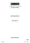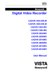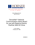
1
1081-1781-1981MR英文中性说明书样本
To:
Fr: 响石数码技术部
料号:4.C.A.0.L006121-0000
品牌:英文中性
封面纸质
铜板纸(印刷黑白 )
内页纸质
通普纸
技术审核
颜
色
黑白
业务校对
尺
寸
420mm ×297mm
拟制
核准
日期
LCD MONITOR
USER MANUAL
REV: 1.0
P/N:ZZXXMRCE01
PDF 文件使用 "pdfFactory Pro" 试用版本创建 www.fineprint.cn
2011-06-17
10"MR
17"MR
19"MR
LCD WITH BUILT-IN DVR USER MANUAL
Foreword
This manual may contain technical inaccuracies, unconformity against the function and operation
of the product, or typographical errors. This manual will be updated in accordance with product
features reinforcement. The described product or program will be improved and updated regularly.
The updating will be added into the new version without notice.
Due to the time limits, the limited proficiency of the editor, we hope that you can give valuable advice in
order to gradually perfect the contents of this manual.
-1-
PDF 文件使用 "pdfFactory Pro" 试用版本创建 www.fineprint.cn
LCD WITH BUILT-IN DVR USER MANUAL
Catalogue
Important Safeguards………… ………… ……… ………… … ……… ……… …………4
Chapter 1 General…… ……… … ……… ………… ……… ………… ……… …………5
1.1 General… ……… ………… ………… ……… …………………… ……… …………5
1.2 Main Function… …………………………… …………………………… …………5
Chapter 2 Installation… …… … …… … … …… … …… … … ……… … …… … …… …7
2.1 Equipment and Components Checking…… … ……… … …… … ………… ………7
2.2 Front Panel…… ………… ………… ……… ………… ………… ……… …………7
2.3 Rear Panel…… … ……… ………… ………… ……… ………… ………… …… …8
2.4 Remote Control……………………………………… ……………………………10
2.5 Hard Disk Installation………………………………………………………………12
2.6 Connection…………………………………………………………………………12
Chapter 3 Menu…………………………………………………………………………14
3.1 Menu Guide…………………………………………………………………………14
3.2 Menu Operation……………………………………………………………………15
Chapter 4 Operating instructions………………………………………………………16
4.1 Power On……………………………………………………………………………16
4.2 Preview Setup………………………………………………………………………16
4.2.1 Video Channel Preview Area…… ………………… ……………………………16
4.2.2 System State………………………………………… ……………………………18
4.2.3 Toolbar……………………………………………………………………………18
4.3 Record Setup…………… ………… ………… ………………… ………… ………19
4.3.1 Record Manually…………………………………………………………………20
4.3.2 Plan Record Setup……………… ………… ………… ……… ………… ………20
4.4 Camera Control… …………………………… …………………………… ………21
4.4.1 PTZ Control………………………………………………………………………21
4.4.2 Motion Detection Setup……………………………………… ………… ………23
4.5 Playback………… …………………………………… ………… ………… ………23
4.6 Backup………………………………………………………………………………25
4.7 Alarm Setup…………………………………………………………………………25
4.7.1 Alarm Input…………… ………… ………… ……………………………………25
4.7.2 Alarm Linkage………… ………… ………… …………………………… ………25
4.8 Network Connection………………………………………………………………26
4.8.1 Network Setup……………………………………………………………………26
4.8.2 Web Client Operation……………………………………………………………26
4.8.2.1 Web Interface Brief Introduction………………………………………………29
4.8.2.2 Remote Equipment Data Parameter Setup……………………………………30
4.8.2.3 Remote File Playback and Download…………… ………… ………… ………32
4.8.2.4 Remote Log Review……………………………………………………………32
4.8.2.5 Remote Equipment Update……………………………………………………32
4.9 Equipment Maintenance……………………………………………………………32
4.9.1 Log Review………………………………… …………………………… ………32
4.9.2 System Update……………………………………………………………………32
4.9.3 Equipment Information………… ………… ………… ……… ………… ………32
4.9.4 Maintenance………………………………………………………………………33
4.9.5 Restore Factory Setting… ………………… ………… ……… ………… ………33
4.10 Advanced Setup… ……… ……… ………… ……… … ……… … …… … ………33
4.10.1 User Management……………… ………………………………………………33
4.10.2 Camera Advanced Setup…… … ………… ………… ……… ………… ………34
4.10.3 Network Connections… ………………… ………… ……… ………… ………34
Chapter 5 Appendix… …… … … … … … … … … … … … … … … … … … … … …… 35
5.1 Appendix 1: Specification…………………… ………………… …………………35
5.2 Appendix 2: Hard Disk Capacity Calculation Method (For Your Inference) ……38
5.3 Appendix 3: System Default Informationv…………………………………………40
-2-
PDF 文件使用 "pdfFactory Pro" 试用版本创建 www.fineprint.cn
LCD WITH BUILT-IN DVR USER MANUAL
CAUTION
RISK OF ELECTRIC SHOCK
DO NOT OPEN
CAUTION:TO REDUCE THE RISK OF ELECTRIC
SHOCK,DO NOT REMOVE THE BACK.
NO USER SERVICEABLE PARTS
INSIDE. REFER SERVICING TO
QUALIFIED SERVICE PERSONNEL
Graphic Symbol Explanation
The lightning flash with arrowhead symbol, within an equilateral triangle, is intended to alert the
user to the presence of uninsulated 'dangerous coltage' within the product's enclosure that may
be of sufficient magnitude to constitute a risk of electric shock to persons.
The exclamation point withinan equilateral triangle is intended to alert the user to the presence
of important operating and maintenance (servicing) instructions in the literature accompanying
the appliance
Warning - To Prevent Fire Or Shock Hazard, Do Not Expose This Monitor
To Rain Or Moisture.
This Product Must Be Earthed.
Product Specification Is Subject To Change Without Notice.
-3-
PDF 文件使用 "pdfFactory Pro" 试用版本创建 www.fineprint.cn
LCD WITH BUILT-IN DVR USER MANUAL
LCD WITH BUILT-IN DVR USER MANUAL
IMPORTANT SAFEGUARDS
P/T/Z Agreement
Caution
Pelco-P、Pelco-D、Samsung、Panosonic、
LILIN
Pelco-P
P/T/Z Bout rate
1200、2400、4800、9600
2400
P/T/Z address
Enter sub-menu setting directly
Channel no. 1
Color setting
Brightness/Contast/Chromo/Saturation:
8\8\8\8
8\8\8\8
Motion sense
Highly sensitive, Standard sensitive, Low sensitive Standard sensitive
Motion event
response
Trigger record, Alarm output, Sound alarm,
upload center
Power source is dedicated on the rear of the set. It contains high voltage Parts. lf you remove the cover, it may cause fire
or electric shock. Do not remove the cover by yourself.
1. Read lnstructions:
All the safety and operating instructions should be read before the appliance is operated.
2. Follow lnstructions:
All operating and use instructions should be followed.
3. Cleaning:
Unplug this monitor from the wall outlet before cleaning. Do not use liquid cleaners
or aerosol cleaners. Use a damp cloth for cleaning.
Camera
setting
4. Water and Moisture: Do not use this monitor near water, for example, near a bathtub, wash bowl, kitchen
sink, laundry Tub, in a wet basement, or near a swimming Pool, and the like.
5. Accessories:
6. Ventilation:
7. Object and Liquid
Entry:
8. Repair(Servicing):
9. Replacement Parts:
10. Safety Check:
Video loss response Alarm output, sound, upload center
Disable
Internet link
PPPoE Staid IP, Dynamic achieve IP, PPPoE
Staid IP
Internet address
Enter sub-menu to setup directly
192.168.0.10
Subnet
Enter sub-menu to setup directly
255.255.255.0
Gatway
Enter sub-menu to setup directly
192.168.0.1
HTTP port
Enter sub-menu to setup directly
80
Network
Signal port
setup
Enter sub-menu to setup directly
5050
Media port
Enter sub-menu to setup directly
6050
DNS addres
Enter sub-menu to setup directly
202.103.24.68
Do not place this monitor on an unstable stand, tripod, bracket, or table. The
monitor may fall, causing serious injury to a child or adult, and serious damage
to the appliance. Use only with a cart, stand, tripod, bracket, or table
recommended by supplier, or sold with the monitor.
Slots and openings in the cabinet are provided for ventilation and ensure reliable
operations of the monitor and to protect it from overheating, and these openings
should never be blocked by placing the monitor on a bed, sofa, rug, or other
similar surfaces. This monitor should never be placed near or over a radiator or
heat register. This monitor should not be placed in a built-in installation such as
a bookcase or rack unless proper ventilation is provided or supplier instructions
have been adhered to.
Never push objects of any kind into this monitor through openings as they may
touch dangerous voltage points or short-out pa rts that would result in a fire or
electric shock. Never spill liquid of any kind on the monitor.
Do not attempt to repair this monitor yourself as opening or removing covers may
expose you to dangerous voltage or other hazards. Refer to qualified service personnel.
When replacement parts are required, be sure the service technician uses replacement
parts specified by supplier or have the same characteristics as the original parts.
Unauthorized substitutions may result in fire, electric shock or other hazards.
Upon completion of any service or repair to this monitor, ask the service
technician to perform safety checks to determine that the monitor is in proper
operating condition.
11. Retain Instructions: The safety and operating instructions should be retained for future reference.
-4-
PDF 文件使用 "pdfFactory Pro" 试用版本创建 www.fineprint.cn
Trigger the current
channel to record
Alarm
Dynamicy domian Enter sub-menu to setup directly
name
Disable
Auto log in
Enter sub-menu to setup directly
Disable
Communion
Document
Enter sub-menu to setup directly
Disable
Alarm input
properties
Normally On/ Normally Close
N. O.
Alarm Linkage
Trigger record, Alarm output, Sound alarm,
Linkage PTZ
Trigger Alarm
output/ sound
-41-
LCD WITH BUILT-IN DVR USER MANUAL
LCD WITH BUILT-IN DVR USER MANUAL
Chapter 1 Introduction
5.3 Appendix 3: System Default Informationv
1.1 General
This series is a quadruplex built-in DVR product with functions of AV preview, record, playback and
Table 5-2 System Default Data
Setting item
internet browse.
Item in menu
Faulty
With professional, high performance LCD driver and intelligent audio & video solution, user-friendly
GUI and practical industrial designs, this series is quite suitable for civil applications such as home, stores,
Internet bars and small offices besides the common security & surveillance applications.
LANGUAG E
Traditional Chinese, Simple-Chinese,
English
Simple-Chinese
Camera Syetem
PAL、NTSC、SECAM
Auto adapt to the video source
1.2 Main Features
Compression
Syestem
setting
R ecord Resolu tion
CIF
Summer Time
America Canada Great Britan Ireland,
Portagul, exc
Disable
12-hour,24-hour
12 -hour
Time format
CIF
l 4/8/16 channels PAL/NTSC/SECAM video input and H.264 compression standard with each
channel being compressed independently in real-time CIF resolution.
l 4 channels audio input and G.726 compression standard with each channel being compressed
independently in 24Kbps.
Remark: 10"MR,17"MR support 4 channels video input. 19"MR support 8 channels video input.
l Video and audio signal compress to have compound bit-stream. Audio and video synchronization.
Keyword
Enter sub-menu to setup directly
Admin:888888
User:666666
Record plan
Enter sub-menu to setup directly
24-hour standard record
Record quality
Best, High, Bette
High
Also support record video stream only.
l Four-level selection of record quality and self-defined bit rate and frame
rate supported.
l Adjustable video parameters.
l Multi-area motion detection.
l OSD of channel name and time supported
Record
PAL:Full、12、6、3、1、User setup
Record fame rate: NTSC:Full、15、7、3、1、User setup
l Manual record and schedule record supported. The schedule record types include: timing, motion
Ful
SECAM:Full、12、6、3、1、User setup
Record
detection, alarm, motion detection | alarm.
l One SATA interface. One SATA hard disk supported.
l Backup and clip record files through USB flash disk, portable USB HDD, and USB CD/RW
Record source
Video, video & audieo
Superposition
information
Channel title,Channel title & Time, Time Channel title & Time
Sub code rate
Frame rate and Code rate faulty setting
Frame rate:1-15 frame/s
Code rate:32-512 kilobit/s
Video & audieo
supported.
Preview and playback
Disable
Frame rate:15
Code rate:288
l Preview and playback support Simultaneous output of local, CVBS, network.
l Up to 4 channels playback in fast play mode, slow play mode, rewind and single frame forward
supported.
l OSD of channel name and time supported.
l Status displaying of local record, alarm and motion detection supported.
-40-
PDF 文件使用 "pdfFactory Pro" 试用版本创建 www.fineprint.cn
-5-
LCD WITH BUILT-IN DVR USER MANUAL
LCD WITH BUILT-IN DVR USER MANUAL
Control
l
l
Controlling of PTZ and dome supported.
l
Setting and calling preset, sequence and track supported.
Ala rm
Alarm recordCaculative way
Note 1:Caculate the HD interspace (Di) for sigle channel firstly: Suppose alarming rate is α%, size of
HD is S, number of channel is n,
Di = (S / n) * α%
l
Local alarm (includes exception and motion detection) triggered handling supported.
l
Alarm linkage: trigger record, linkage alarm output, linkage PTZ preset, sound alarm, report to alarm
Center.
Note 2:Then check out record time (T) for each channel, to get the Di for every hour,
Dt = Di / T
Note 3:Check out code rate of all channel:
Network
l
TCP/IP supported
l
PPPoE supported
l
Dynamic access to IP address, Dynamic Host Configuration Protocol (DHCP) supported.
l
DDNS supported
l
Visit video files in hard disk though network neighborhood support.
l
Real-time preview, downloading and playback remotely through network supported.
l
Controlling of PTZ, configuring device parameters, acquiring device status and logs, and upgrade
Dc = Dt *(8*1024)/ 3600 = Dt * 2.2756 (Kbit/s)
remotely through network supported.
l
Local recording through network supported.
-6-
PDF 文件使用 "pdfFactory Pro" 试用版本创建 www.fineprint.cn
-39-
LCD WITH BUILT-IN DVR USER MANUAL
LCD WITH BUILT-IN DVR USER MANUAL
Chapter 2
5.2 Appendix 2: Hard Disk Capacity Calculation Method (For Your Inference)
To Caculate HD capacity that connects to DVR on base of the requrie of record(compress parameter of
coding setting)
l
Installation
2.1 Equipment and Components Checking.
Refer to the '' Package Contents '' for counting device fittings when you receive the product.
Record---Caculation way
Note1:First to caculate the max HD interspace (Si (Mbyte) )of single channel in 1hour, suppose code rate
of the channel is D(Kbit/s), then the fomula as below:
2.2 Front Panel
Panel indicator light and buttons as below:
Si = (D*3600)/(8*1024)= D * 0.439453125 MB
H. D
AL ARM
IR
PWR
Note2:Make out the time for record saving T(hour),and caculate the max interspace of signle channel,
fomula as below:
St = T * S1
Note3:Make the no. of channle of this equipment as n, S 1 is capacity of channel 1, S 2 is capacity of
channel 2. Then the total capacity of the HD as:
l
Picture 2-1 Front panel schematic diagram
Chart 2-1 Front panel buttons information
NO. Type
Alarming record Caculation way
Suppose alarming rate is a %, the total capacity of HD for alarming record could be caculate with refer to
the total capacity of timing record Sc.
①
Calculate the compression bit rate for recording T hours.
Common record
Note 1:Suppose the capacity of the hard disk as S, the total numbers of the channel as n, The capacity of
hard disk needed per channel supposed as Di is:
②
Arrow
Buttons
1. iris zoom in
Numbers
0-9 number buttons
1. for input numbers
2. One key channel selection in preview mode.
PDF 文件使用 "pdfFactory Pro" 试用版本创建 www.fineprint.cn
4. focus out
H.D
Hard disk indicator. Green. Blinks when reading/writing. Black when
non-operation.
Alarm
Light
ALARM
Event alarm indicator. Light when alarming. Black when not when not
alarming.
Infrared
Light
IR
Remote control indicator light. Green. It's flickering when remote control
is operated. Or it's off.
PWR
Two colors. It's red when standby. Green when start to work.
DVR
Dt = Di / T
-38-
3. focus in
1.Confirm operations in menu mode.
2. Select record type in setting schedule.
3. Change status of the current motion detection block.
Note 2:Suppose the total recording time is T hours, the capacity of the hard disk needed per channel
supposed Dt is:
Dc = Dt *(8*1024)/ 3600 = Dt * 2.2756 (K bit/s)
2. iris zoom out
Arrow
Including 4 buttons:
Buttons:
1. When in menu mode, press 【 】,【 】to move the selection boxes. Press
【 】,【 】 【 】,【 】to select submenu parameters.
【 】,【 】 2. Switch ActiveX on screen.
Di = S / n
Note3:The bit rate of all the channels supposed as Dc IS
Information
PTZ
Operation
Key
Buttons
Sa = Sc * α%
l
Name
③
LED
-7-
LCD WITH BUILT-IN DVR USER MANUAL
LCD WITH BUILT-IN DVR USER MANUAL
Auxiliary function button
1.Switch between signal image and multi images in preview and playback
mode.
2.Enter/exit continuous selection when setting motion detection area and
record mode.
3. Set start time and end time in file search.
Function
support to operate by cursor, remote controller and front panel
OSD
1.Play/Pause
2.One key file search.
Record
Stop
Main
Functions
Could upgrade to support other language ;Desktop show recording and alarming status
visually,Panel show recording and alarming status
go to next frame
④
Navigation embeded; Support Traditional Chinese, Simple-Chinese and English.
5 mode of record:Manual, timing, motion sense linkage, alarm linkage, motion sense &
alarm linkage
Play-back interface show directly the play-back status and the current play speed.
Support real time play-back of multipe channels of vidio & audio .
Play-back Support speed play/slow play/ single frame forward/speed back, 4 channels play-back,
max 16 times .
One key enter Manual recording.
One key PTZ control.
Backup
One key system setup.
Return to upper menu. The same as 【ESC】button on the remote control.
Internet
function
Volume adjustment 0~8
Acknowledge alarm.
⑤
2.3
Power
on/off
Backup record.
Press it to power on/off device.
Hold pressing 3 seconds to shut down forcibly.
PTZ
control
Support Pelco-P、Pelco-D、Samsung agreements,Support upgrade of agreement;
Support Pan, Tilt, Zoom Preset zoom,cruise and locus and ON/OFF control assistance.
Alarm
manage
Support 4 channels alarm input which could be setup as Normally On, Normally Close
Support Motion detection,support Alarm for video loss( Network port could setup)
Alarm could trigger to recording, Link PTZ preset point and sound alarm.
Support alarm message to send to Web user port or user port software
User
manage
Double user manage, support user key word setup, key word restoration and Permission
setup .
Operation permision of Admin user could not be changed, including all operation
Assistan
function
Hardware watch-dog circuit. Monitor will re-open autoly when equipment stop
responsing for more than 30s.
RS-422
TV-OUT
ALM- OUT
Rx- Rx+ Tx - Tx+
3
A-I N
3
- +
V-IN
1
1
NET
USB
DV
19V
G G
4
3
2
1
ALM- IN
A-OUT
2
4
2
4
Picture 2-2 10" monitor rear panel
RS-422
Support Ipv4, PPPOE client, DHCP client, TCP/UDP agreements. Offer Web user port
and user port softward. And sopport remote configuration,brosxe video,local record, local
and remote play-back, remote PTZ control. Internet transfer suppports indendent coding.
Delay less than 300ms LAN.
Operation Operating and alarming message auto record.
Record file, including
file
Rear Panel
ALM -OUT
Rx- Rx + Tx- Tx+
Support U-disk, USB hardware, USB CD/DVD backup. Backup format H.264 RAW
directly.
V-I N
A-IN
OUT
- +
V
3
1
3
1
A
4
2
4
2
USB
NET
DV
1 9V
G G
4
3
2
1
ALM-IN
Picture 2-3 17" monitor rear panel
-8-
PDF 文件使用 "pdfFactory Pro" 试用版本创建 www.fineprint.cn
-37-
LCD WITH BUILT-IN DVR USER MANUAL
LCD WITH BUILT-IN DVR USER MANUAL
Parameter of audio & video
RS-422
Video code
standard
H.264 Baseline
Syestem
PAL/NTSC/SECAM
- +
A-IN
3
V-OUT
1
7
5
V-IN
3
1
USB
NET
DV
19V
G
Video code
A-OUT
ALM-OUT
Rx- R x+ Tx- Tx +
G
4
3
2
1
2
4
ALM-IN
8
4
6
2
PAL:352×288(CIF)NTSC: 352×240(CIF)
Picture 2-4 19 " monitor rear panel
Video frame rate
Param eter
25F/S/CH(PAL) 1,3,6,12,25 us er se tup。30F/S/CH(NTSC)
1,3,7,15,30 use r set up .
Chart 2-2 Rear panel connections
32kbps-2048kbps(14M byte/hour - 922M byte/hour)
NO.
o f vide o
Video output code
Preview resolution
Playback resolution
Audio code
PAL:720×576(D1),Holizental 550,Vertiacal 450
①
NTSC:720×480(D1),Holizental 550,Vertiacal 400
PAL:352×288(CIF),Holizental 300, Vertiacal 250
②
NTSC:352×240(CIF),Holizental 300, Vertiacal 220
Description
4 channels
8 channels
USB interface (up): USB 2.0
USB interface (down): USB 1.1
Support USB storage device, USB mouse, USB burner. Suggest to use USB1.1 to connect USB
mouse, 2.0 to connect storage device.
V-IN: 4 channels video input, BNC interface
(1Vp-p,75Ω)
G.726ADPCM
V-IN: 8 channels video input, BNC interface
(1Vp-p,75Ω)
③
Paramet er
of audio
Other
Audio Frequency
2W×2
A-IN: 4 channels audio input, RCA interface (2Vp-p,impedance:600Ω)
Input/output
8KHz
V-OUT: 4 channels video input, BNC interface (1Vp-p,75Ω)
No. of track
single channel
Sample digit
16 bit
Voltage
DC 14-19V2.5A,positive inside/negative outside,with power adapter
Operation
temperature
0℃-+50℃
④
NET: RJ45, 10/100 self-adaptive
Dimensions
(W×H×D)
ALARM OUT: 1 channel switch-level output, relay characteristic
30VDC 1A,125VAC 1A
⑤
Operation humidigy 10%~90%RH
Power
A-OUT: 1 channel audio output, RCA interface (2Vp-p,impedance:600Ω)
25W(HD)(10 " MR)
37 W(HD)(17 " MR)
295.6mm×135mm×44.8mm(10" MR)
392mm×431.8mm×86mm(17" MR)
-36-
PDF 文件使用 "pdfFactory Pro" 试用版本创建 www.fineprint.cn
40W(HD)(19 " M R)
RS422 interface: for duplex operation of data transmitting and receiving.
Tx+: transmit data + interface
Tx-: transmit data - interface
Rx+: receive data + interface
Rx-: receive data interface
ALARMIN:4 channels switch-level input, N/O. or N/C.
G: For ground connection.
429.6mm×386.1mm×88mm(19" MR)
⑥
Power input interface: DC 19V / 2.5 A
-9-
LCD WITH BUILT-IN DVR USER MANUAL
2.4
LCD WITH BUILT-IN DVR USER MANUAL
Remote Control
Charter 5 Appendix
5.1 Appendix 1: Specification
①
②
Table 5-1 Technical data
Item
③
Main informaiton
④
⑤
Coding video input
⑥
Coding audio input
Linus 2.6 operation system
4 operation :Record, reverse, preview & internet browse
4 channels video input, BNC jack,
8 channels video input, BNC jack,
1Vp-p, 75 Ω
1Vp-p, 75 Ω
PAL(625lines 50f/s),
PAL(625lines 50f/s),
NTSC( 525lines, 60f/s),
NTSC( 525lines, 60f/s),
SECAM(625lines 50f/s)
SECAM(625lines 50f/s)
4 channels input, RCA jack, 2Vp-p,600 Ω
CVBS output
1:RCA jack,1Vp-p,75 Ω
Audio output
1:RCA jack,2Vp-p,600 Ω
Outer
port
⑦
8 channel produc
4 channel produc
1:BNC jack,1Vp-p,75Ω
2:Por t US B 1.1 & U SD 2.0 P ostposition
USB port
⑧
Suppor t USB me mor y equ ipment, USB mou se, U SB copy equi pme nt
It ' s sugg est that P ort U SB 1.1 c onnect with U SB mouse, Port USB 2 .0 co nne ct to
me mor y equ ipm ent.
RS242
1:Dis patch er/r ecei ver
In netn et po rt
1:RJ4510/100M Auto-ad apte d
Alam input
4 c hann els in put
Alarm outp ut
1 c hann el ou tput , relay characteristic 30VDC 1A,125VAC 1A
SATA por t
1: Su ppor t 1pc of SATA HD, uppport 1T H D
⑨
Picture 2- 5 Remote Controller
-10-
PDF 文件使用 "pdfFactory Pro" 试用版本创建 www.fineprint.cn
-35-
LCD WITH BUILT-IN DVR USER MANUAL
4.10.2
Enter Tool
LCD WITH BUILT-IN DVR USER MANUAL
Camera Advanced Setup
System menu Camera setup
Chart 2-5 Remote control buttons
Adanced Setup interface
Motion event response
When motion event appear in destined area,there' s some linkage response to setup: Trigger record, Triger
alarm output, Sound alarm, upload center
Name
①
Power on/off
Turn on/off the device, same as the
Function
【CN/EN】:Switch from Chinese to English, or reverse.
Buttons
【ID】:Set ID of remote controller.
③
Numbers
Input numbers or select to switch among relevant channels.
④
Function
Buttons
【DEL】:Delete
⑤
Function
Buttons
②
Note :Setup of Motion area and Sensitive, please refer to 4.4.2 Motion detection setup
Video loss response
When video of selected channel loss, linkage response of video loss event could be setup, including:
Trigger alarm output, Sound alrm, Upload center
Camera offset
Including horizontal offset and vertical offset. Setup up and down, left and right offset for video image.
Play control
button of front panel
button of front panel. 。
:play in slow mode/fast rewind,
:Play/pause,
:go to next frame,
:fast forward,
:go to next section ,
:Go to previous section,
Enter<Tool> - (System menu>--<Network setup> advanced setup
interface
Setup PPPOE
Choose PPPoE, press to enter PPPoE interface for USER and Key word.The equipment will dial no.
when information loggin successfully. After dialing, the IP address and other network message will be
showed on the interface.
Arrow buttons :The same as arrow buttons of front panel
:Picture capture
⑦
Function
:Switch from single split to multiple splits view mode
Buttons
:Auxiliaries, same as the
Setup dynamic domain name
Choose to turn on Dynamic domain name, press to enter interface for setup dynamic domain name.
Choose one of domain name server, log in address of dynamic domain name, user and keywor.
⑧
Adjust Picture
:Adjust brightness up/down。
parameters
:A djust contrast up/down
button of front panel
【PROG】:S et sequence ,
【PTZ】:Enable PTZ control, same as the
Note: This product now offer 6 kind of domain name server.
to enter auto registation interface. Then log in IP address &
button of front panel.
:Return to upper menu, same as the
To setup DNS serve address, DNS serve IP address should be log in.
Setup auto registation
Choose to turn on auto registation. Press
port of host computer,interval of register
Record, same as the
:Stop,
⑥
4.10.3 Network Connections
Description
NO.
【SET】:Set parameters, same as the
⑨
button of front panel.
button of front panel.
Function
【×】:Cancel alarm notifications, same as the
Buttons
【PRESET】:S et preset
button of front panel.
【CALL】:Call preset .
File communnicate
Cross to open File communcation. To visit record file in DVR HD via neighber of PC.
The way to visit communicate file
Open network neighger, log in IP address, such as \\192 .168.10.220 to enter login interface. Log in
Admin user name and keyword to get into list of communicate. Click videoout file to look over record file.
Note: When play software is setup, the record file could be play by Windos Media Player
-34-
PDF 文件使用 "pdfFactory Pro" 试用版本创建 www.fineprint.cn
【SEQ】:Call sequence .
【SCAN】:Scan automatically .
Note: The following buttons are disabled currently: 【ID】、【CN/EN】、【PROG】、【PRESET】、
【CALL】、【SEQ】、【SCAN】 、
、
、
-11-
.
LCD WITH BUILT-IN DVR USER MANUAL
LCD WITH BUILT-IN DVR USER MANUAL
2. 5 Hard Disk Installation
The hard disk is not included in the factory fittings. Users can mount suitable hard disk by calculating its
capacity referring to '' 5.2 appendix 2 '' .
4.9.4 Maintainance
HD formatting
Please make sure that important record file is backup before HD formatting.
Please stop all record services before HD formatting, and follow the tips on interface to get HD formatting.
Hard disk installation:
1.Take off the hard disk box on the rear
2. Instal the hard disk into the box and fix it.
3. Connect Hard disk power line and SATA data line( Pay attention to the direction of connection)
4. Fix the hard disk box to the rear of equipment
Logout user
Enter Tool System munu reserve setup, and choose Logout, then the system get back to preview interface
and Login interface. Other operateion could be done when correct keyword is logged in.
Tips 1: Hard disk choosing notice: please choose video surveillance special used hard disk, recommended
4.9.5 Restore Factory Setting
By hard disk manufacturer. Make sure suitable for long time and large data read-write. Please
Purchase from formal channels to have good quality.
Enter Tool System munu reserve setup, and choose Restore Fctory Setting, the system will remind
RECONFIRM or not. Press yes, and the system will be resotred to Defautl setting when re-opened.
Tips 2: Please format the hard disk after installation before use. Refer to '' 4.9 Equipment Maintenance ''
Notes 1: Please refer to 5.3 Appendix 3 System Defaut Data for Defaute data of each menu
Notes 2: Restor factory setting does not change language, Time and Camera Syetem in system; does not
change IP address, Subnet mask and HTTP of network information.
2. 6 Connection
Power Input
Make sure the input VAC is matching to the power adapter. Connect the power adapter to the power
supply. If the connection is correct, the LED will light.
Tips: Please use the power adapter contained in the package to avoid any defect.
Video Input
The video input interface is standard BNC interface. The input signal must be PAL/NTSC BNC(1.0 Vpp,75Ω).
Tips: The video signal cable should keep away from the interference of strong electromagnetism and city
4.10 Advanced Setup
Note 1: This charpter for 8 channels product only. For 4 channels product, please enter Web USER port
for correlative operation and setup.
Note 2: The login user must have permision on setup for Operation in this charpter. Please user Admin
user to log in and operation.
4.10.1 User Management
Enter Tool Syetem Menu System Setup Adanced seting interface, choose Permission manager to
enter User Permision Setup interface
Permission setup including Local and remote Permission setup items. See below the picture:
electric field.
Audio Input
The audio input interface is RCA interface (2Vp-p,600Ω). The audio impedance is a little bit high.
Please use active sound collection device or active microphone. And the audio signal cable should keep
away from the interference of strong electromagnetism and electric field.
Network Input
The equipment has standard RJ45 interface. Can be connected to LAN or WAN conveniently. Please
provide sufficient bandwidth for fluent and clear image network transmission when connecting to
network.
Picture 4-7 Permission setup
User Direction: Up/Down/Left/ Right to focus on some chosen item. Use OK to confirm or cancle your
selection. Press ENTER to preserve your setup.
-12-
PDF 文件使用 "pdfFactory Pro" 试用版本创建 www.fineprint.cn
-33-
LCD WITH BUILT-IN DVR USER MANUAL
LCD WITH BUILT-IN DVR USER MANUAL
File Download :
The File download operation part is on the right bottom of the screen.
Click
to set the storage directory of the file selected. Click 〖Download〗 to start downloading.
Alarm Input and Output
The alarm input device should be the type of GND connected alarm or voltage input alarm, Can be
N/O(normally open) or N/C(normally closed).
The level request of voltage-mode alarm signal: low level range: 0~2V, high level range: 5~15V.
The green angle pins of signal cable are supplied for access of PTZ and alarming devices. Please follow
4.8.2.4 Remote Log Review
Click
to enter interface of Log search and Backup. Log search support 4 way of searching: All,
Type, Time ,Type & Time. Choose search way and channel no., and click SEARCH to have log
information that tally with require.
these steps to connect:
1 . Pull out the green angle pins.
2 . Loosen the screws on the plug by small crosshead screwdriver. Put the signal line under the spring piece
inside the plug, tighten the screws.
3 . Plug in the connected pins into green angle pin socket.
4.8.2.5 Remote Equipment Update
Enter selection of Equipment Parameter, Equipment manage. User Browse to choose file that needs
upgrading, click Start for upgrading. In case exception accure during upgrading, choose stop upgrade to
stop your operation.
Connect PTZ
4.9 Equipment Maintenance
Tips: Some PTZ have different communication protocol, baud rate and address code. Please refer to the
Enter Tool ,System Menu, Equiepemnt maintainance interface to have operation of maintain for
correlative equipment
Connect the PTZ control interfaces to RS422 TX+ and TX- in the rear panel. The method is as above.
instruction and setup the matched parameter.
Video Output: VGA/Monitor(CVBS Output)
4.9.1 Log Review
1. Choose log type that you want to check: All/ Operation/ Exception/ Alarm
2. Choose the time that you you want to check
3. Press Search, detail information is showed on interface
Note 1: When there 's record informtaion in your search result, enter【 】on right side of the log to play.
Note 2: Log can record max 30000pcs record currently. The way of record wash out: To replace the
earliest log information autoly.
4.9.2 System Update
The product support update way: Local USB, IE, User port software
By USB: Make sure USB is correctly connected and upgrade program is copied in USB before operation.
Upgrading by tips on the interface.
After upgrading, there will Reboot tips on the screen. The system would run with new software when
rebootted.
By IE: Please refer to 4.8.2.2
By user port software: Please refer to illustrate of User port software
4.9.3 Equipment Information
HD Capacity: Show the capacity and left capacity of current HD that connects to equipment.
Haredware Edition: Show information of current Hardware Edition
Software Edition: Show information of current software Edition
Issue Date: Show issue date of current software.
-32-
PDF 文件使用 "pdfFactory Pro" 试用版本创建 www.fineprint.cn
-13-
LCD WITH BUILT-IN DVR USER MANUAL
LCD WITH BUILT-IN DVR USER MANUAL
Chapter 3
3.1 Menu Guide
User Management Option Card
Including User Limit and Keyword Setup. Information interface at equipment port: Toolbar System
Menu, Syetem setup, Adanced Setup
When login with Admin, User limit and keyword could be change directly.
Menu
Language
Video Standard
Equipment Management Option Card
Including remote equipment upgrading and Time revising
<Time revising> can change time of equipment to the time of connected PC
Record Resolut ion
System
DST
Time Format
Time Setting
Pass word Setting
Advanced Se tting
Came ra CH
PTZ Protocol
Color Se tting
Manual
Record
Motion Detection
M osaic
Advanced Se tting
Playback
Net
<Equipment status> Option card
Including HD and channle status information
4.8.2.3 Remote File Playback and Download
Re cord Frame Rate
OSD Se tting
Advan ced Setting
Press
to enter interface of Playback searchk, Play and Download.
File Search
Up right side of interface is for File searching. Please setup object file, Channel no. file type, Interval.
Click Search, the form would show file list of search result. Cross the file to enter Play/Download
opreation.
Netw or k
IP Addr ess
Subne t Ma sk
Gate way
Me dia Port
File play
Left side of interface is for playing. There include Play display frame, Play controller, information
interface Choose the object file, Press PLAY. And the chosen record file will be play in the order of
time.Guagage as below picture:
Next Page
Play controller as below picture:
HTTP Por t
Command Port
Alarm Input CH
Ptz Contr ol
Record Quality
PTZ Baud rate
Video
PTZ ID
Tool Bar
Recor d S chedule
Recor d S ource
Record
System
Vide o CH
Al ar m Input Type
Alarm
Event Handling
Advanced Se tting
Clear Alarm
Maintenance
Save
status display
Upgrade
Save & Exit
Shut Down
Exit
4 channels
alarm input
Log Vie w
Resto re Defaults
Logout
1 channels
alarm input
Manage H DD
HDD Capac it y
Ha rdwar e Ve rsion
Sof twar e Ver sion
P lay;
Pause; Stop; Go to next frame; Fast play option (The speed of playing will be doubled by each
clicking. It includes: 2X, 4X, 8X, and 16X); Slow play option (The speed of playing will be half down by
each clicking. It includes 1/2X, 1/4X, 1/8X, and 1/16X); Enhance contrast; Reduce contrast; Enhance
brightness; Reduce brightness; Open/close voice; Go to previous file; Go to next file (
and
is
enabled only when multiple record files being selected to play); Snapshot (the storage directory can be set
).
on the pop-up screen by clicking
The information of the record file selected will be displayed in the area shown as the figure below. It
includes device's IP address, current play speed, channel number and start/end time of the record file.
Software Release Date
Picture 3-2 Menu Structure
-14-
PDF 文件使用 "pdfFactory Pro" 试用版本创建 www.fineprint.cn
-31-
LCD WITH BUILT-IN DVR USER MANUAL
LCD WITH BUILT-IN DVR USER MANUAL
Picture Preview
Including: Amend of Preview picture parameter on 4 channel, Sound preview, Record, Print screen
function operation
, :Add / reduce picture contrast
,
:Add / reduce picture Brightness
:On/off Web user port Sound monitor. Icon turns to Green when record on.
:On/off Web user port monitor. Icon turns to Green when record on.
:Shot screen for the video of this channel
:Turn off Preview of current channel
Note: Click
to set the storage directory of record files and pictures captured.
PTZ Operation
PTZ operation interface is similar to Equipment port. Please refer to 4.4 PTZ Control
Note: For assistance equipment, IE port support 4pcs.
4.8.2.2 Remote Equipment Data Parameter Setup
Press
3.2 Menu Operation
Press 【SET】 to enter system menu.
Press 【●】to enter manual record setup.
Press 【 ‖】to play record file.Press
Press 【PTZ】to enter PTZ control.
Tips: 【XX】 for menu buttons, <XX> for equipment interface display menu and menu options,
【XX】 for front panel and remote control button.
Menu Selection
The highlight menu is the current active one. User can move highlight icon to the menu needed using
【▲】、【
】、【 】、【 】button, and press
button to confirm selection, or press
【ESC】or
button to return to upper menu.
Menu Items Type
Selection box: User can move highlight icon to the selection box needed using 【 】、【 】 button,
and press 【OK】 button to confirm selection. Multiple items are allowed to be selected together at once
by left clicking mouse.
to enter interface of Equipment parameter setup. Al parameter of equipment
List box: User can move highlight icon to the sub menu needed using 【
mouse to select directly. Only one item can be selected here.
】、【
】 button. Or roll
(Equipment parameter) Option card
Including Server collation information, Network collacation informaiton, Active register, Edition
information. All the setup, except “Active register”, can be showed and changed on interface of
Equipment Toolbar, Syestem setup.
Edition box: when in edition box, user can type in numbers directly by pressing number buttons or
】 、【
move cursor position using 【
】、【
】、【
】 . Press 【DEL】 to delete the
character before cursor and press
or 【ESC】 button to exit.
Active register: To setup information from equipment actively registe to Center manage
software.Including Network servicer address, port and registe interval.
Sub screen button: Press it to pop up sub screen. When in sub screen, select【Confirm】to save
configuration and return to the upper menu. Press 【ESC】 or select【Cancel】 to return to the upper
menu without being saved.
Note: If the current IP mode is dynamic achieve, the IP address is alloted and unchangeble.
Channel parameter option card
Including motion detection setup, Video loss setup,Channel superposition setup, Image code stream and
Frame rate setup, Image parameter setup, Recording time plan tale.
Note: Can setup in one channel firstly. And after setup, copy the information to other channels.
Seriel port parameter option card
Including PTZ agreement of channel Camera, baud rate, address code setup. Information interface at
equipment port : Toolbar System setup Camera setup
Use 【 】、【
】 to move highlight icon to any of the selection boxes. Press
button to switch
to another selection status. Use【▲】、【 】 to specify the sub menu value where sub menu selections
exist.
Save/Exit
Exit: User can click
button on the right upper corner, or single right click mouse, or press 【ESC】
button to enter into the Save & Exit screen. When you exit, you can enter <Toolbar>--<System>-<Save Setup> .You can select exit directly or exit after being saved.
Note: There are three different ways to take effect: take effect instantly, take effect after being saved, and
take effect after restarting device. Please refer to the navigation for details.
Alarm parameter option card
Including Alarm inpuot Setup, Triger setup, Linkage setup. Information interface at equipment port:
Toolbar System setup, Alarm Setup。
-30-
PDF 文件使用 "pdfFactory Pro" 试用版本创建 www.fineprint.cn
-15-
LCD WITH BUILT-IN DVR USER MANUAL
LCD WITH BUILT-IN DVR USER MANUAL
Chapter 4 Operations instructions
4.8.2.1 Web Interface Brief Introduction
4.1 Powe r On
Startup After powering on correctly, the Power LED will light green. The monitor will be auto-start.
Please refer to 2.6 Rear Panel Connection for details of connection method. The login box will appear
then. Please select proper user and type in relevant password to log in.
Note1: It costs about 60 seconds to start up, please wait for a moment.
Note2: Modify password by selecting <Toolbar>-<System>-<System Setup>-<Password Setup>. Set
as indicated, new password will take effect instantly.
Note3: Default password for User is 666666; default password for Admin is 888888. Admin password can
be restored to factory defaults by short-circuit the "JP 10 " or " JP 15 " on main board. User
password can be reset by Admin by IE in 【User Management】
Note4: The DVR will buzz and " NO Hard disk " appears when without hard disk.
System Setup
Language: Please enter <Toolbar>-<System>-<System Setup>-< Language> to set language.
Picture 4-6 IE Interface
Date/Time: Please enter <Toolbar>-<System>-<System Setup>-<Time Format> to set time format.
Aderess bar
Show IP address of login equipment
12 hours and 24 hours are supported. Please enter <Toolbar>-<System>-<System Setup>-<Time
Setup> to set date and time.
Tool bar
Video Standard: Please enter <Toolbar> ? <System> ? <System Setup> ? <Video Standard> to set video
standard. PAL, SECAME, and NTSC are supported. Please set according to the parameters of camera.
Note1: In order to avoid record files ' time confusion, you ' d better stop recording before modifying system
time.
Note2: " Language " and " Time " will take effect instantly. "Record Resolution " and " Video Standard "
will take effect after being saved. Will take effect after [Save&Exit]
Note3: Users can refer to the navigations on the bottom of the main screen to look for relevant guides.
Meanwhile, the structure will present " take effect instantly " /" take effect after being saved "
4.2 Preview Setup
After start-up system, the screen has live view area/system status/toolbar. Right click mouse in preview
mode or press
on the front panel , the Toolbar will appear.
4.2.1 Video Channel Preview Area
Videos, OSD of channel name, motion detection notifications will be displayed on the screen.
-16-
PDF 文件使用 "pdfFactory Pro" 试用版本创建 www.fineprint.cn
To read and change Equipment parameter
Search and playback of equipment record file and local file.
Search and Lead-out of equipment operation log.
Setup of local record file store list.
Swift operation of video image amont Full screen, Single image, quad image.
User Log out, Equipmetn reboot, IE dis-alarm operation
Information tip zone
When network connection is broken or abnormal, the alarm notification of "No heartbeat of device,
please check the network!" will be displayed in the right up side of the main screen. After recovery of
network, the preview will be displayed automatically.
When alarms of remote notification occur, the alarm notification with alarm input number contained such
as "Device alarm: IO alarm, IO input x" will be displayed in the right up side of the main screen.
When alarms of motion detection with remote notification occur, the alarm notification with the alarm
channel number contained such as "Device alarm: motion detection, channel 1" will be displayed in the
right up side of the main screen.
When alarms of video loss with uploading to center occur, the alarm notification with the alarm channel
number contained such as "Device alarm: video loss, channel x" will be displayed in the right up side of
the main screen.
-29-
LCD WITH BUILT-IN DVR USER MANUAL
LCD WITH BUILT-IN DVR USER MANUAL
Preview Operation
Can setup Trigger of Alarm output: Trigger Sound Alarming, Upload center
Alarm , Linkage Alarm output
<Alarm> Tab
View Mode Switching
Preview can be " single "/ " quad " / "9 images " .
When in 4/9 splits view mode, the tile with highlight white border is the current selected one. User can
use mouse or press 【Direction】 buttons to switch to another tile. If the audio output device is connected,
the audio can also be previewed together with video.
User can select to display a single particular channel by pressing the corresponding 【Numbers】buttons
1~8. When in single split view mode, user can enter into 4/9 splits view mode by pressing
button
directly, or reverse.
Note: For 8 channels, the view mode can be directly switched by toolbar. Please refer to 4.2.3 " Tool Bar "
<User> Tab
The password and authority of Admin and User can be modifying.
Image Parameters Setup: Please enter <Toolbar> - <System>- <Camera Settup> - <Image Setup> to set
brightness, contrast, hue and saturation. It will take effect instantly.
Note1: User can set image parameters of one channel one time or all channels together at once by
selecting 〖All〗 in <Camera Channel>. It is similar in other screen when user wants to set four channels
together at once: select〖All〗 in <Channel>.
Note2: In preview mode, brightness, contrast can be adjusted by remote control directly.
OSD Setup
The OSD of channel name and system time is supported. Please enter <Toolbar>-<System>-<Record
Setup>-<OSD Setup> to set. The channel name will be displayed on left upper corner and the channel
time will be displayed on the righter corner of the screen.
Channel Status Display Area
The channel status includes: "motion detection " / " common recording " / "motion recording " /
" alarm triggered recording " / " external alarm input" / " alarm output ". Indication of "motion detection" /
"common recording" / "alarm recording" / "input alarm recording" will be displayed on the right upper
corner of screen. The details are as follows:
<Device> Tab
User can adjust DVR time accordance with PC time.
<State> Tab
Device states can be viewed directly.
PTZ
Support up to 2 auxiliary channel on local side and 4 auxiliary channel on IE side: 1、
2、3、4。
:indicates " motion detection " . The setup of motion detection includes sensitivity and area selection.
Please refer to ".4.2 motion detection setup " .
:Blue indicates " ommon recording ". Please refer to " 4.3 recording setup ".
:Green indicates "motion detection triggered recording ".
:Red indicates " alarm triggered recording " .
:Grey indicates " manual recording ".
Indication of "external alarm input " / " alarm output " will be displayed on system status column or
Toolbar. The details are as follows:
4.2.2 System State
In preview mode, the system status bar will display current system status, including: "External alarm
input" / "Alarm output" / "Hard disk capacity" / "Number of the client connection" / "System time."
Please refer to "4.2.1 channel video preview area" for alarm input/output status.
-28-
PDF 文件使用 "pdfFactory Pro" 试用版本创建 www.fineprint.cn
-17-
LCD WITH BUILT-IN DVR USER MANUAL
LCD WITH BUILT-IN DVR USER MANUAL
:The 4 icons indicate the alarm input status. When alarming, it changes into red
alarm input can trigger multiple events handling. Please refer to "4.7 Alarm Setup".
. External
Form 4-2 IE port added setup function
Content
:The last icon indicates alarm output. When alarming outputs occurs, it changes into red
IE port could collacate Equipment name
:Volume state. It's red when the system is mute.
:Indicates hard disk being ok. The number indicates the percentage of the total
capacity of the hard disk.
:Indicates " ard disk error " Or " No hard disk " .
User PPPOE dial, DNS address could be set.
:Indicates client connection. The number shows client linking number.
:Indicates "No client connection "
<Server> Tab
Can setup manage of IP information
4.2.3 Toolbar
Right click mouse or press <OK> under Preview to have tool bar as below:
Can setup visiting way as via Registed domain name
Picture 4 - 1 Tool bar of 4 channel product
:Hide the tool bar.
:Setup parameter of equipment. See detail at 3.1 Menu Guide
Channel name can be user-defined, and Font and size of letter can be setup.
:Manual record. See 4.3.1 Manual record for details.
:To search, playback, backup of record file in the Hard disk. See 4.5 File playback and 4.6 Backup
Motion detection can setup: Trigger Sound Alarm, Upload to Alarm Center, Linkage
alarm output.
Motion detection can linkage to Multi channel record, and Equipment port setup
could only be 1 & 1 corresponding.
for details.
:PTZ operation. Please see 4.4.1 PTZ Control for details.
:Alarm cancle. Click this button will pop a message to show the present alarm information.
:Power off .
、
:To set the view mode of " Single splits view " , " 4 splits view " ,
:To adjust the screen, 8 pixels per unit.
、
、
:To reduce or increase screen in vertical direction.
:To reduce or increase screen in Horizontal direction.
<Channel> Tab
Picture 4-2 Tool bar of 8 channel product
:Hide the tool bar.
:Setup parameter of equipment. See detail at 3.1 Menu Guide
Can setup Trigger of Video loss Alarming: Trigger Sound Alarming, Upload center
Alarm , Linkage Alarm output
:Manual record. See 4.3.1 Manual record for details.
:To search, playback, backup of record file in the Hard disk. See 4.5 File playback and 4.6 Backup for
details.
:PTZ operation. Please see 4.4.1 PTZ Control for details.
:Alarm cancle. Click this button will pop a message to show the present alarm information.
:Power Off
-18-
PDF 文件使用 "pdfFactory Pro" 试用版本创建 www.fineprint.cn
-27-
LCD WITH BUILT-IN DVR USER MANUAL
LCD WITH BUILT-IN DVR USER MANUAL
、 、
view"
4.8 Network Connection
、
:To set the view mode of "Single splits view", "4 splits view" , "8 splits view" ," 9 splits
:To adjust the screen, 8 pixels per unit.
4.8.1 Network Setup
、 :To reduce or increase screen in vertical direction.
、 :To reduce or increase screen in Horizontal direction.
Please enter <Tool Bar>→<System>→<Network Setting>→<Network Connection>, there are three
connection types: Static IP, DHCP and PPPoE.
Static IP:If this type selected, please type in IP address, subnet mask, and gateway. User can ping
network to check its connection status.
DHCP:If this type selected, a DHCP server should be set in network. A dynamic IP of device will be
assigned automatically and displayed on IP Address column.
PPPoE:Click 〖>>〗, the PPPoE setup screen will appear. Type in user name and password and click〖
OK〗 to confirm. System will dial automatically. After accomplishing dialing, the IP address will be
assigned and displayed automatically on IP Address column.
The following are types of ports:
HTTP Port:It is the port number of browsing through IE. Default is 80.
Signal Port:It is the first entry port for communication between web client and device, which is mainly
used for controlling of log-in, log-out, real-time preview, remote playback, and remote download, etc.
Media Port:It is for media stream transmitting including real-time stream, voice stream and file stream
etc.
Note1: All of these settings of network will take effect after being saved.
Note2: Some products need enter <Network Setting>→〖Advanced Setting>>〗to set PPPoE.
、 、 、 :To move the screen up, down, left, right
:To zoom out the screen to largest and show in central.
Note 1: When mouse moves to the tool bar icon, the indication information will come out to help users to
understand.
Note 2: When video source is PAL, screen display range max is 720 x 576; When NTSC, screen display
max 720×480.
4.3 Record Setup
Record type contains manual record and schedule record. The priority of manual record is higher than
schedule. If the record schedule is confilct with manual record, the manual record will be processed firstly
until the namual recod being cancled.
Record types include "Common recording "/" Alarm Trigger Recording " /" Motion Detection Recording"
/ " Motion Detection Triggered Recording " . Each of them is indicated with grid of different color. And
each color indicates a particular record status. Please see Fig 4-3 Record Schedule for detail.
Record resolution: Fixed in the CIF fromat options if the device only supports CIF format. Other formate,
" CIF " /" 2CIF" /" D1 " show in the menu.
4.8.2 Web Client Operation
Open IE Browser, log in IP address of equipment to enter IE log in interface
Note 1: When use PPPOE or DHCP to connect to network, recheck of IP address is asked when
equipment reboot.
Note 2: When it is the first time to use IE log in the equipment, the system will tis to load install insert.
Follow the Notes to operate. The default user name is Admin, keyword is the same as keyword
for equipment software port log in.
Note 3: For 4 chanels product, IE port has more setup funciton compared to Equipment port, see Form
4-2. For 8 channels product, function at locat port is achieved. For detail, please refer to 4.10
Advanced Setup.
Record quality: Best768Kbps, High640Kbps, Better512Kbps, Common384Kbps, And user setting can
help user to set bit rate.
Record Frame rate: if the curretn selection is PAL, the frame rate options are All, 12, 6, 3, 1 Customized.
Defulty is All, 25fps for PAL and 30fps for NTSC.
Record Resource: Video for vidoe only or ‘Video And Audio” for recording video and audio.
Record Resource: "Video" for video only or "Video and Audio" for recording video and audio. Substream: sub-stream can be enabled or disabled. After enabled, press
to set sub-stream, to set sub
steam frame rate and bit rate. Sub stream frame rate rages from 1 to 15 frames, bit rate ranges from 32K to
512K.
Note 1: Please refer to Appendix 6.2 for the methods of calculating HDD capacity.
Note 2: The setting of Sub-stream for some products must enter〖Advanced Setting〗.
-26-
PDF 文件使用 "pdfFactory Pro" 试用版本创建 www.fineprint.cn
-19-
LCD WITH BUILT-IN DVR USER MANUAL
LCD WITH BUILT-IN DVR USER MANUAL
4.3.1 Record Manually
Please enter ( Tool Bar> - < Manual Record> to let the specific channel record or not.
Presss 【●】 button to start/stop recoding manually.
Note : The type of the video recorded manually is “common recording”
4.3.2 Plan Record Setup
Enter < Tool Bar>--<Syesem Menu>--< Recod Setup> interface, choose <Record Plan> to enter
4.6 Backup
Enter Tool bar, Backup control interface, search and choose the record file, prss BACKUP to get inter
backup interface.
Thy system will search and show all Backup equipment. Choose equipment and type of document, press
BACKUP to start. If no equipment searched, there will Notes on interface and stop Backup. Make sure
USB is well connected.
Note: Type of record: H.264, Raw & MP4. Backup MP4, equipment will backup
Play software in USB autoly. When play softwar e is setup, the record file could be play by Windos Media
Player
4.7 Alarm Setup
For connection of Alarm input and Alarm output, refer to 2.6 Connection
Enter Tool bar, Syestem menu , Alarm Setup interface, to setup Alarm
Note: All setup of alarm should be saved when exit to effect.
4.7.1 Alarm I nput
Picture 4-3 Record
1:The current recording channel number
2:The record Schedule
3:Description of record type
User are free to select a week day or the day of a period of time System provides a recording option for
hours every day or a week day. Unit is hour. Ond grid indicates one hour.
Setup of all channel much be coincident. Then choose <All> to enter < Record Plan>
1. User< Direction: Up/Down/Left/Right> TO choose a time grid.(Unit as Day or Hour)
2. Specify the recording type by repeat pressing
button or double left clicking moush,(the color of
the grid will change relevantly)
3. Repeat step 1 and 2 to finish setup. Press < Enger> to confirm. The setting will take effect after being
saved.
Note 1: Usee can copy the current setting onth neighboring grid by pressing <Fn> or
button firsty,
<Direction> button secondly, and then the <Fn> or
button again to exit. Or user can drag
mouse to set.
Note 2: When motion detection recording is selected, the mothion detection sestitivity and area should be set
ahead. Please refer to 4.7.2 Alarm Linkage for details.
-20-
PDF 文件使用 "pdfFactory Pro" 试用版本创建 www.fineprint.cn
Alarm input including Normally On and Normally Close
Normally On: Open circuit normally. When alarm signal trigger, circuit connected.
Normally Close: Short circuit normally. And disconnected when Alarm signal trigger.
4.7.2 Alarm Linkage
When Alarm happened,there’s some linkage response to setup: Trigger record, Trigger alarm output,
Sound alarm, upload center
Note 1: To linkage record when alarming, Time schedule of Alarm record should be setup in Record time
schedule.
Note 2: PTZ preset point 1 can be setup when Alarming. Choose channel no. of Linkage PTZ to enter
setup interface. When setup finished, PTZ will saved it
Note 3: Alarm linkage of 4 channels product: Sound and Upload center. The setup of them is in Network
user port. For detail, pls. Refer to 4.8.2 Web user operation and table 4-2.
-25-
LCD WITH BUILT-IN DVR USER MANUAL
LCD WITH BUILT-IN DVR USER MANUAL
4. Setup of Time period, Channel no. and Time Scale, then press 【 】、【 】to move focus to Search
and use
to operat. Time scale will show the searched record.
5. After searching over, press 【Fn】or
button to pop-up the timeline for selecting start point.
Press 【 】,【 】 buttons to move timeline, press 【Fn】or
to confirm selection. Press 【Fn】
or
again to pop-up the second timeline for selecting stop point, press 【 】, 【 】 buttons to
move timeline, press 【Fn】to confirm selection.
After all settings, move highlight icon to〖Play〗using 【 】,【 】 buttons, and press
to start playing. move highlight icon to〖Backup〗using 【 】,【 】 buttons, and press
to backup.
button
button
4.4 Camera Control
4.4.1 PTZ Control
PTZ Parameter setup
Enter <Tool Bar>, <System Menu>--<PTZ Setup) to set camera channel,Protocal, Boud rade and ID.
Note: The different PTZ onctrolled by one P CI should have corresponding PTZ ID. There are 16 PTZ
ID supported. Currently:0-15
PTZ operations
In preview mode, select a tile first (in 4/9/16 splits view mode, the selected tile is with highlight white
border) using mouse or <Nurbers> buttons, and then enter <Tool Bar>, PTZ control to the PTZ Control
interface that described as the table below:
Play control
:Fast backward Press to circle between “ 8 times fast backward and 16 times fast backward.
:Pause the current play, or stop the current pause.
:Stop playing.
:Click to control speed of Forward, the availabel forward speed are 1X, 8X , 16X, 1/2X, 1/4X
:Go to next frame
: Press to switch from single split view mode to multi split view.
I nd i ca ti on
S pe e d
16X
16X fas t forward
8X
8X fast f orward
1X
N ormal playing
1/2X
1/4X
1/ 2X forwa rd
1/4X forward
8X
8X fast backwards
16X
16X fas t backwa rds
Note: When playback only one channel, the image will displayed in full-screen.
Picture 4-4 PTZ Control int
-24-
PDF 文件使用 "pdfFactory Pro" 试用版本创建 www.fineprint.cn
-21-
LCD WITH BUILT-IN DVR USER MANUAL
LCD WITH BUILT-IN DVR USER MANUAL
4.4.2 Motion detection setup
Table 4-4 PTZ Operation Description
NO.
Description
Name
Motion detection Setup including Sensitive Setup and Area Setup. Sensitive has High, standard, low for
choice. Enter Tool Bar, System Menu, Camera Setup, Motion detetion to setup. Use mouse to setup
Motion detection area.
Panel operation: Enter motion area setup interface, the whole screen is devided as 16 x 12 area. User
【 】、【 】 direction key to move the focus among each block. Area setup as
①
Click the arrow icons to control direction of PTZ.
call sequence or run scanning. Please refer to the PTZ
Direction Click the center icon to
manual for details of PTZ scanning mode.
②
Speed
Set the turning speed of PTZ camera.
③
Advanced
Click
button ).
④
Focus
Click to focus-in and focus-out (it is disabled for cameras with automatic focus).
⑤
Iris
Click to make the image brighter or darker (it is disabled for cameras with automatic
iris adjustment).
4.5 Playback
Open/close auxiliaries:
Click
to open and click
to close. Different functions respond to different
protocols. The auxiliaries include light, rain brash, and power etc. please refer to PTZ
manual for details.
NOTE: Up to 2 auxiliaries are supported on device side. Up to 4 auxiliaries are
supported on client web side.
File Search
Enter Tool Bar, Playback control interface, choose date and channel that you want. Press Search, and
result will be showed on interface. Different color refers to different record type. Please refer to Table 4-3
Record schedule. Choose time period by mouse or front panel.
and
to show/hide the advanced setting screen (the part under the
⑥
Auxiliary
⑦
Zoom
Click to zoom in/zoom out (it is disabled for cameras with automatic focus).
⑧
Prese
Preset is to set camera position, focus, zooming, and iris position, and then mark them
in numbers for later calling. Up to 16 presets can be set currently. Set preset:
1. Select the preset number you want to name as. 2. Position the camera as desired
position including direction, focus, iris and zoom value.
3. Click on the set button
.
call preset:
1. Select the preset number you want to call.
2. Click on the go-to button
.
Clear/reset preset:
1. Select the preset number you want to clear/reset.
2. Click on the clear button
.
⑨
Sequence is a running route of camera that passes through multiple presets. Set
sequence:
1. Select preset number you want to call.
2. Click on set button
.
Sequence 3. Repeat step 1 and 2 to add the other presets till finishing.
4. Click on run button
.
Clear sequence:
Click on
button to clear sequence.
⑩
Track
Track is a continuous running route of camera. Set track:
Click on
to start setting.
Move camera as the track and pattern you want it to run.
Click on
again to finish setting.
Click on
to run track and click again to stop running.
NOTE: Whether Track is supported or not is depending on the type of PTZ.
-22-
PDF 文件使用 "pdfFactory Pro" 试用版本创建 www.fineprint.cn
1. User <Direction: UP/DOWN/LEFT/RIGHT> to move focus to a certain block, press
to choose
the currrent status.( The chosen status is the block in high bright blue color.)
, user <Direction: UP/DOWN/LEFT/RIGHT> to copy the status to neighber
2. Press 【Fn】or
Block. When setup of first motion area is finished, press 【Fn】or
to exit.
3. Repeat step 1 and 2 to finish setup of second motion area.
to exit.
4. When setup finished, press 【ESC】 or
Picture 4-5 File Search
Use mouse to choose Time Period.
Front panel: Use 【
】、【 】 to move the focus among selection.
1. Move the focus to Date, and use 【
】、【 】to change time.
2. Move the focus to channel, press OK to choose or cancle.
3 . Move the focus to
, press 【OK】 to Zoom in or Zoom out time scale. When the scale is too
large to show on the page, move focus to
, user
to operate.
-23-