1
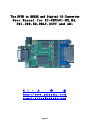
T h e GPIB to RS232 and Digital-IO Converter
User Manual for KI-GRUA01-R2,R4,
DR1,DR2,SR,DRLY,DUTY and XR1
K I
-
工
作
室
htt p : // w w w . p h k a k u . c o m
e-m ai l : k i t e c @ p h k a k u . c o m
page1
INDEX
Preface:
The design concept for KI-GRUA01 ------------------------------------1
1.
Specification of KI-GRUA01 ------------------------------------------4
Interface of GRUA01 ------------------------------------------------4
Electrical-SpecificationI of GRUA01-R2------------------------------4
Support to GPIB-Function -------------------------------------------5
The SR-Function-output of KI-GRUA01 --------------------------------6
Material and Size of KI-GRUA01-PCB ---------------------------------7
The configuration of KI-GRUA01 RS232-PORT interface-----------------7
Control-of-Data-Flow for KI-GRUA01-RS232-Port-----------------------7
Configuration of KI-GRUA01-RS232-Baudrate --------------------------8
The TTL-RS232-PORT of KI-GRUA01-------------------------------------9
The data format of KI-GRUA01-Digital-IO-PORT ----------------------11
The flowchart of KI-GRUA01-Digital-IO-PORT-Internal-Control -------11
The configuration for KI-GRUA01-GPIB-Address-----------------------12
2.
The inspection method of KI-GRUA01----------------------------------14
To inspect function of Rs232 PORTa and PORTb for KI-GRUA01---------14
To inspect function of Digital-IO PORTx and PORTy for KI-GRUA01----16
3.
Application-Example for KI-GRUA01-----------------------------------19
Example for controlling KI-GRUA01-Digital-IO-PORT with KI-GC1201---19
Examples for controlling KI-GRUA01-RS232-PORT with KI-GC1201-------21
To test KI-GRUA01-RS232-Port with Angilent 82357B------------------21
To test KI-GRUA01-Digital-IO-Port with Angilent 82357B-------------21
Programming examples for KI-GRUA01 with PC and Visual C++----------23
VISUAL C++ communication-subprograms for KI-GRUA01-RS232-PORT -----24
page2
The Electrical specification of KI-GRUA01-R2 :
Power voltage
: DC 6.8V to 7.5V
Power current
: DC 150 mA (no load) and DC 250 mA (Max)
GPIB Connector
: DB24, Female
RS232 Connector
: DB9, DTE, Female
Power-Jack
: 2.1mm*5.5mm*11mm
(Voltage for the center of Power-Jack is positive)
The ports for interface :
TTL level output port number for RS232
: 1 (PORTa).
RS232 level output port number for RS232 : 2 (PORTa and PORTb).
Port number for Digital-IO
: 2 (PORTx and PORTy).
Port number for IEEE GPIB
: 1
Interface voltage :
the output voltage of Tx pin for RS232-TTL connector : DC 5V
the input voltage of Rx pin for RS232-TTL connector
: DC 5V
the output voltage for pin of Digital-IO
: DC 5V
the input voltage for pin of Digital-IO
: DC 5V(Max)
Support to GPIB-Function :
SH, AH, L, T, SR
The configuration of KI-GRUA01 when it is powered on :
RS232-BAUDRATE
: 9600 (It can be changed by instruction 'RS232=xxxxx').
GPIB-ADDRESS
: 24,25,26,27 (It can be changed by instruction 'GPIB=xx').
The parameter value of Control-of-Data-Flow :
‘0’
All of the RS232-PORT are configured as Default-Data-Flow-Type and it
can be changed by the instruction of ‘INPUT=n’
The parameter value of Baudrate :
‘1’
The Baudrate of RS232-PORT is configured as 9600 and it
can be changed by the instruction of ‘RS232=n’
The parameter value of GPIB :
‘24’
The GPIB address of Porta, Portb, Portx and Porty is configured as
24,25,26 and 27 and it can be changed by the instruction of‘GPIB=nn’
The parameter of Rs232 interface :
Baudrate
: 2400,9600(default),14400,19200,28800,
38400,57600,115200,128000
Parity
: none
Bit-No
: 8
Stop-Bit-No
: 1
Signal-Line
: RXD(2th pin), TXD(3th pin)
Input-Buffer
: 748 bytes
RS232 Connector of PORTa-Rs232-Level : DTE
The PCB of KI-GRUA01-R2 :
Material : FR4 double-side and surface with Immersion gold.
Size
: 5.49cm x 6.48cm
page3
The Electrical specification of KI-GRUA01-R4 :
Power voltage
: DC 6.8V to 7.5V
Power current
: DC 150 mA (no load) and DC 250 mA (Max)
GPIB Connector
: DB24, Female
RS232 Connector
: DB9, DTE, Female
Power-Jack
: 2.1mm*5.5mm*11mm
(Voltage for the center of Power-Jack is positive)
The ports for interface :
TTL level output port number for RS232
: 1 (PORTa).
RS232 level output port number for RS232 : 4 (PORTa,PORTb,PORTc AND PORTd).
Port number for Digital-IO
: 2 (PORTx and PORTy).
Port number for IEEE GPIB
: 1
Interface voltage :
the output voltage of Tx pin for RS232-TTL connector : DC 5V
the input voltage of Rx pin for RS232-TTL connector
: DC 5V
the output voltage for pin of Digital-IO
: DC 5V
the input voltage for pin of Digital-IO
: DC 5V(Max)
Support to GPIB-Function :
SH, AH, L, T, SR
The configuration of KI-GRUA01 when it is powered on :
RS232-BAUDRATE
: 9600 (It can be changed by instruction 'RS232=xxxxx').
GPIB-ADDRESS
: 2,3,4,5,6 and 7 (It can be changed by instruction 'GPIB=xx').
The parameter value of Control-of-Data-Flow :
‘0’
All of the RS232-PORT are configured as Default-Data-Flow-Type and it
can be changed by the instruction of‘INPUT=n’
The parameter value of Baudrate :
‘1’
The Baudrate of RS232-PORT is configured as 9600 and it
can be changed by the instruction of‘RS232=n’
The parameter value of GPIB :
‘2’
The GPIB address of Porta, Portb, Portc, Portd, Portx and Porty
is configured as 2,3,4,5,6 and 7 and it can be changed by the
instruction of‘GPIB=nn’
The parameter of Rs232 interface :
Baudrate
: 2400,9600(default),14400,19200,28800,
38400,57600,115200,128000
Parity
: none
Bit-No
: 8
Stop-Bit-No
: 1
Signal-Line
: RXD(2th pin), TXD(3th pin)
Input-Buffer
: 748 bytes
RS232 Connector of PORTa-Rs232-Level : DTE
The PCB of KI-GRUA01-R4 :
Material : FR4 double-side and surface with Immersion gold.
Size
: 5.49cm x 6.48cm
page4
Preface
The design concept for KI-GRUA01.
The interface for the instrument:
Because the Packaged-Message and Packaged-Data are used to
make communication between the interface of LAN or USB on
the instrument and the other interface for the controller
(Such as PC). Each interface for LAN or USB need to supply
the driver to the interface-controller for which interface
is able to communicate with the controller. If there are
many different brands of instrument to be used, the design
of application program for controller will be very difficult.
But the Raw-Message and Raw-Data are used to make
communication between the interface of GPIB or RS232 on the
instrument and the other interface for the controller
(Such as PC), the interface of GPIB or RS232 will be able to
Communicate directly with the interface of controller.
Under the situation of utilizing many different brand of the
Instrument, there are no need of additional driver and the
design for program of controller will be simple as an instrument
to be used.
The LAN is usually used to make communication with the
Long-Distance or the Big-Data transmission, the cost of LAN
Included of instrument and program design will be very
expensive.
If there are no need for communication with the Long-Distance
or the Big-Data transmission, it would be cost down and raise
up the working efficiency
to use the instrument of the GPIB
or the RS232 interface.
The price of the instrument with RS232-interface is lowlier than
that with GPIB-interface but the multi-instrtuments with RS232
interface linked each other through a controller of interface
will be difficult.
The multi-instruments with RS232 interface is able to link with
this GPIB interface through the multiple RS232 interface of
KI-GRUA01, and then this GPIB will be made for connection
with the controller of interface and other instruments which
page5
have GPIB-interface.\
The internal structure of KI-GRUA01.
The function of KI-GRUA01/DR1/SR1/DRLY/DUTY/XR1:
One set signal of GPIB-Interface will be converted into:
2 sets TTL-Level of RS232-Interface (KI-GRUA01-R2/DR1/DUTY/XR1) or
1 sets TTL-Level of RS232-Interface (KI-GRUA01-SR1)
+
1 set RS232-Level of RS232-Interface (for KI-GRUA01-R2) or
2 set RS232-Level of RS232-Interface (KI-GRUA01-DR1/DR2/SR1/DRLY/DUTY/XR1)
+
2 sets Digital-IO interface (KI-GRUA01-DR1/R2/XR1) or
1 sets Digital-IO interface (KI-GRUA01-DR2/SR1/DRLY)
+
1 sets Serial-Communication-Controller interface (Called it as SCCI below)
(KI-GRUA01-DR2/SR1/DRLY/DUTY/XR1)
1 sets RELAY of LEG5 interface (KI-GRUA01-SR1/DUTY/XR1)
+
+
1 sets Square-Wave input and the output with Programmable Duty-Cycle
interface (KI-GRUA01- DUTY-XR1)
+
1 sets Square-Wave input and the output with Programmable Frequency
interface (KI-GRUA01- XR1)
and then many electrical interfaces above mentioned are controlled
through KI-GRUA01 by GPIB Controller.
page6
page7
page8
page9
The feature of KI-GRUA01:
(a) The 2 sets of instruments which are low-cost and have the
interface of RS232 only will be able to link together
and link with the other instruments which have the
interface of GPIB through KI-GRUA01.
(b) a GPIB-Controller and the two sets of Digital-IO-Port
(16-IO-PIN) for KI-GRUA01 will be able to control
the electronic-circuit-board and also read the digital
signal from it.
(c) The GPIB-Controller and PC will be able to control
the instruments of item-a (above-mentioned) after
these instruments have been linked with KI-GRUA01.
The driving of the KI-GRUA01-Interfae-signal will
be taken by Embed-MPU-8051 and Cpld-LC4128. It is
not necessary to add extra PC-Driver, operation
is easy, and many complicating programs for
controlling will be simplified as a program of
Gpib-Application.
For example:
page10
PC can get data from
Barcode-Scanner (for example: ST-66),
Control Relay (LEG-5),
execute instructions input from the
Windows-button of Windows-Program (mentioned as above) and
output exection-result to the log-file
(xxxxxxxxxxxx.log)
automacically through KI-GC1201 ,KIGRUA01 and Winows-Program
(in figures as above).
page11
Download the Visual C++6 source code of CheckLedApp program
Download the PCB-Layout-Document of Relay-Board
Download the Driver of Gpib-Controller KI-GC1201
Download RS232 Windows-APP KiGirax.exe for KI-GC1201
(d) PCB-for-testing-purpose of private-design
example: Digital-to-analog-control-PCB,
LCD-Display-PCB.. etc.
The utilization of TTL-Level RS232 interface is
more simple than that of USB or GPIB, and it is
also linked into the other instruments with
GPIB interface through KI-GRUA01
(e) The hardware size is reduced, working speed of
interface is fast, stability is up-ward, and
cost is down.
1.
The Specification of KI-GRUA01
*Interfaces of KI-GRUA01:
a. IEEE488 GPIB
: 1
b. RS232-DS275orST3232
(RS232 level,DB9,DTE,Connector Pin2=RXD,Pin3=TXD) : 1 PORTa
c. RS232 (TTL level)
:
KI-GRUA01-R2
: 2 PORTa, PORTb
KI-GRUA01-R4
: 4 PORTa, PORTb, PORTc , PORTd
Note:
If RS232-PORTa for item-c and item-b are working at the same
time, the data input from the RS232-PORTa to the IO-Buffer
of KI-GRUA01 will be set-up as unavailable.
d. Interface of Digital-IO
: 2 PORTx, PORTy
*Electrical specification of KI-GRUA01 :
Power-Voltage (input from external)
Power-Jack
: DC 6.8V
(Minimum)
DC 7V
(Typical)
DC 7.5V
(Maximum)
: 2.1mm*5.5mm*11mm
(Voltage for the center of Power-Jack is positive)
GPIB Connector
: DB24, Female
RS232 Connector
: DB9, DTE, Female
Power-Current (Power-Voltage = DC 7V)
: DC 130 mA (no load)
DC 250 mA (Max)
page12
Interface-Voltage :
RS232-TTL-Interface-Voltage
: 4.85VDC to 5.25VDC (Regulated)
Digital-IO-Interface-Voltage
: 4.85VDC to 5.25VDC (Regulated)
The output of Digital-IO-Pin :
Voltage:
Digital-IO-Interface-Voltage (Max)
Current(Source):
5 mA/Max (each pin)
The input of Digital-IO-Pin :
Voltage: TTL Level (must not excess the Digital-IO-Interface-Voltage)
The Access of Digital-IO-Pin:
Method: Directly-IO-Acess ,that is,
(a) The data input from GPIB-BUS will be
transmitted to Digital-IO-PORT directly.
(b) The data input from Digital-IO-PORT will be
transmitted to GPIB-BUS directly.
(c) The Input/Output-state of Digital-IO-PORT will
be switched automatically.
(d) The Digital-IO-PORT have the function of Latch
when being in the Output-State.
(e) The GPIB-DATA format regard to the input and
output of Digital-IO-PORT :
One Byte PORT-Value + EOI-Signal
The output of RS232 TxPIN :
Voltage:
RS232-TTL-Interface-Voltage (Max)
The input of RS232 RxPIN :
Voltage: TTL Level (must not excess the RS232-TTL-Interface-Voltage)
GPIB-Handshake-Timing (Per Byte):
Data output:
8us/Min
Data input:
50ns/Min
Support to GPIB-Function :
SH1, AH1, L4, T6, SR1
page13
KI-GRUA01 receive data which will be saved in its IO-BUFFER
from RS232-PORT. After already receiving whole BLOCK-DATA
(data+0d0a) , KI-GRUA01 will enable its REQUEST-SERVICE
signal. If all of the data in the IO-BUFFER of KI-GRUA01 are
read by GPIB-CONTROLLER, the IO-BUFFER
will be cleared and the
REQUEST-SERVICE signal will be disabled by KI-GRUA01
.
Description:
GPIB-CONTROLLER gives the Query-instruction to KI-GRUA01 if
instrument needs much time to prepare the data which will be
transmitted to GPIB-CONTROLLER. It will put to use the SR
function of KI-GRUA01 to escape making the GPIB-ERROR for
reading data from instrument too fast or wasting too much time
for reading data from the instrument too slow.
SR-Function output:
Serial Poll will output 3 bytes,
First Byte
= 50(Hex) : KI-GRUA01 IO-Buffer
First Byte
= NULL
Second Byte
= It meas that IO-Buffer of KI-GRUA01
is ready.
: KI-GRUA01 Out-Buffer
is not ready.
get ready just time for the
High-Byte-Value of the data number.
Third Byte
= It meas that IO-Buffer of KI-GRUA01
get ready just time for the
Low-Byte-Value of the data number.
Description :
To take KI-GC1201 Controller
Instruction
Rp
: SPOLL 24
: 80
Description:
Because 80 = 50Hex is means that :
KI-GRUA01 IO-Buffer is ready.
Instruction
Rp
: SPOLL& 24
: 80,1,64
Description:
First Byte
: 80
Because 80 = 50Hex is means that :
KI-GRUA01 IO-Buffer is ready.
Second Byte
: 1
page14
Third Byte
: 64
data Number in KI-GRUA01 IO-Buffer = 256*1+64
= 320
Instruction
Rp
: SPOLL&# 24
: 500140
Description:
First Byte
: 50
50Hex of first-byte is means that KI-GRUA01
IO-Buffer is ready.
Second Byte
: 01(Hex) = 1
Third Byte
: 40(Hex) = 64
data Number in KI-GRUA01 IO-Buffer = 256*1+64
= 320
KI-GC1201 GPIB-Controller(firmware Version 2.1 and further) is
to support the function for Multiple-Byte-Serial-Poll
(Serial-Poll with Multiple-Byte) and take the job of testing
the SR-Function of KI-GRUA01.
*The configuration of KI-GRUA01 when it is powered-on :
RS232-BAUDRATE
: 9600
GPIB-ADDRESS
: 24,25,26,27 (It can be changed by instruction 'GPIB=xx').
(It can be changed by instruction 'RS232=xxxxx').
Control-of-Data-Flow : All of the RS232-PORT are Default-Data-Flow-Type,
that is,the value of Input is '0', and that can
be changed by the instruction of 'INPUT==x'.
*The Material and Size of KI-GRUA01-PCB:
Material:
FR4 which is Double-side and surface with Immersion gold
Size:
5.49cm x 6.64cm
*Protocol of KI-GRUA01 RS232-PORT interface:
Baudrate
: 2400,9600(default),14400,19200,
28800, 38400,57600,115200,
128000
Parity
: none
Bit-No
: 8
Stop-Bit-No
: 1
Signal-Line
: RXD, TXD
IO-Buffer
: 748 bytes
Output format of PORTa-Rs232-Level : DTE
(Same with the output format of PC-Rs232-PORT)
page15
Note:
(a) Because KI-GRUA01 does not support RTS, CTS, DTR and
DSR of Handshake-Signal-Line, the RS232-HandshakeOption of RS232-PORT for instrument must set-up as
OFF, and then the KI-GRUA01 will be able to link
instrument with RS232-PORT.
(b) Some old type of instrument whose RS232-PORT operation
put to use the RTS, CTS, DTR and DSR of the HandshakeSignal-Line and which have no switch for the function
of the RS232-Handshake-Option is unable to link with
KI-GRUA01. There are two solutions:
(1) Utilizing the GPIB interface to link the instrument
, GPIB-Controller and the other instrument.
(2)It should put the signal of the DATA-SET-READY and
CLEAR-TO-SEND which are read through the DSR and
CTS pin by the instrument to be YES. This method is
as below:
,and then link instruments and GPIB-Controller
through the RS232-PORT of KI-GRUA01
(c) Instruments whose RS232-PORT operation does not use the
DTR and DSR of the Handshake-Signal-Line is able to link
with KI-GRUA01.
*The method of Data-Flow-Type is setup for KI-GRUA01:
1. The RS232-PORT-DTE of KI-GRUA01 is linked with that of
PC (or
USB-to-RS232 Converter) through
RS232-CABLE-FOR-CROSSOVER.
2. KI-GRUA01 is connected with power +7V (Min +6.8V, Max+7.5V).
3. The Application-Program of KiGirax.exe, WindowsXp Hyper-Terminal
or other Windows RS232-Terminal are executed and the Baudrate
page16
of RS232-PORT for PC is setup as 115200.
4. The set-up of Data-Flow-Type for KI-GRUA01:
Instruction format:
a.PORTa and PORTb are set us as Default-Data-Flow-Type.
input=0
b.PORTa is set up as Code-Reader-Data-Flow-Type and
PORTb as Default-Data-Flow-Type.
input=1
Default-Data-Flow-Type:
** It is fit for controlling general test-instrument.
** The data transmitting from instruments to
KI-GRUA01-RS232-Port.
a. Block-Data: The end of Block-Data must be with 0a, and
the bytes of total data must not excess
over 748 bytes.
b. KI-GRUA01 will save the data input from Rs232-Port in its
IO-Buffer until the data is '0a' (the end of Block-data)
from Rs232-Port, and then
set the state of Request-Service-Signal as ON,
and the state of IO-Buffer-Status as READY
(i.e. Serial-Poll-Status-Byte= 80 = 50Hex)
c. GPIP-Controller will read the data in the IO-Buffer
of KI-GRUA01 for RS232.
1. if the state of IO-Buffer-Status is not Ready,
KI-GRUA01 will not transmite data to
GPIP-Controller
2. if the state of IO-Buffer-Status is Ready,
KI-GRUA01 will transmite all of data in IO-Buffer
and signal of EOI to GPIP-Controller
3. if all of data in IO-Buffer are already read by the
GPIB-CONTROLLER, KI-GRUA01 will clear the
IO-Buffer, and
* Setup the state of IO-Buffer-Status as
unavailable
i.e. Serial-Poll-Status-Byte= 0,
page17
* Setup the state of Request-Service-Signal as
off.
** The data and the signal EOI transmitted from the GPIB-CONTROLLER
to KI-GRUA01-GPIB-Port
a.if the data is neither the 0d nor the 0a,
KI-GRUA01 will transmite the data to instrument
through KI-GRUA01-RS232-Port.
b.The number of data are not limitted.
c.if the data is the 0d or the 0a,
KI-GRUA01 will give up the data.
d.if the data is with the signal of EOI:
KI-GRUA01 will transmite data+0d+0a to instrument
through KI-GRUA01-RS232-Port
** 2 sets of RS232-PORT for KI-GRUA01 only hold one
IO-Buffer for common use. When PC give the
query-instruction to one of RS232-PORT(such as PORTb)
of KI-GRUA01 through GPIB-Controller, the next step,
PC must give the read-data-instruction to that of
KI-GRUA01 ,must read the data in output-buffer of
instrument and must send them back to PC through that
of KI-GRUA01 mentioned above. There are no data
carried away.
For instance:
Method with exaction:
SEND? 25 'VSET 5''VOUT?';SEND 26 'VSET 7'
or
SEND 25 'VSET 5''VOUT?';SEND? 25;SEND 26 'VSET 7'
Method without exaction:
SEND 25 'VSET 5''VOUT?';SEND 26 'VSET?';SEND? 25
When the data in output buffer of instrument are
sent back to PC through RS232-PORT of KI-GRUA01
the data-path for address-25 is closed and the
data-path for address-26 is opened,
by the
instruction
"SEND 26 'VSET?'",
therefore the data transmitted to PC from output
page18
buffer of instrument-address-25 will be carried
away.
Code-Reader-Data-Flow-Type:
** It is suit for transmitting a small number of data which
transmition timing is indefinited from instrument to
KI-GRUA01 RS232-PORT:
For example:
Scanner, Barcode-Reader etc.
** The data transmitting from instruments to
KI-GRUA01-RS232-Port.
a. Block-Data:
The end of Block-Data must be with 0d+0a or 0a, and
the bytes of total data must not excess over 32 bytes.
b. KI-GRUA01 will save the data input from Rs232-Port in its
IO-Buffer until the data is '0a' (the end of Block-data)
from Rs232-Port, and then
set the state of Request-Service-Signal as ON,
and the state of IO-Buffer-Status as READY
(i.e. Serial-Poll-Status-Byte= 80 = 50Hex)
c. GPIP-Controller will read the data in the IO-Buffer
of KI-GRUA01 for RS232.
1. If the state of IO-Buffer-Status is not Ready,
KI-GRUA01 will not transmite data to
GPIP-Controller
2. If IO-Buffer-Status is ready
KI-GRUA01 will transmite two sets of Syncronous-signal
(NULL0+EOI), whole data in IO-Buffer and one signal of
EOI.
3. if all of data in IO-Buffer are already read by the
GPIB-CONTROLLER, KI-GRUA01 will clear the
IO-Buffer, and
* Setup the state of IO-Buffer-Status as
unavailable
i.e. Serial-Poll-Status-Byte= 0,
* Setup the state of Request-Service-Signal as
off.
** The data and the signal EOI transmitted from the
page19
GPIB-CONTROLLER to KI-GRUA01-GPIB-Port
a.if the data is neither the 0d nor the 0a, KI-GRUA01
will transmite the data to instrument through
KI-GRUA01-RS232-Port.
b.The number of data are not limitted.
c.if the data is the 0d or the 0a, KI-GRUA01 will give
up the data.
d.if the data is with the signal of EOI:
KI-GRUA01 will transmite data+0d+0a to instrument
through KI-GRUA01-RS232-Port.
** Because Code-Reader-Data-Flow-Type Port-IO-Buffer is private
used and support the synchronous signal, it can prevent the
GPIP-Controller from reading error data from the Port-IO-Buffer
of KI-GRUA01.
Please refer the Application-POrogram as below:
CheckLedApp Visual C++6 Source-Code
** Because the Port-IO-Buffer of Code-Reader-Data-Flow-Type is private
use,there are not data carried away at switching RS232-PORT.
* The method of setting the Baudrate for RS232-PORT of KI-GRUA01:
1. RS232-PORT-DTE for PC (or USB-to-RS232 Converter)
and KI-GRUA01 will be linked together through
RS232-CABLE-FOR-CROSSOVER.
2. KI-GRUA01 make connection with the power(+7v).
3. The appliction programs which are KiGirax.exe, the
Hyper-Terminal of Windows-XP or other communiction
program of RS232-Terminal will be executed and the
RS232-BAUDRATE for PC must be setup to 115200.
4. To setup the RS232-BAUDRATE of KI-GRUA01 RS232-PORT.
Instruction format:
RS232=+BaudrateID+0d0a(Press-Enter-Key)
The relation between BaudrateID and Baudrate-Value:
BaudrateID
Baudrate-Value
0
is
2400
1
is
9600
2
is
14400
page20
(default)
3
is
19200
4
is
28800
5
is
38400
6
is
57600
7
is
115200
8
is
128000
Example:
Input:
RS232=2
(and Press-Enter-Key)
Response:
GPIB:24; BAUDRATE:14400;
Command Baudrate-Value
RS232=0
2400
RS232=1
9600(default)
RS232=2
14400
RS232=3
19200
RS232=4
28800
RS232=5
38400
RS232=6
57600
RS232=7
115200
RS232=8
128000
Description:
The instruction as mentioned above is given to KI-GRUA01
of which BaudrateID for RS232-PORT is set up as 2 and the
BaudrateID will be saved in the flash-memory of KI-GRUA01
IC-SM59264. The KI-GRUA01 will read the BaudrateID after
it is power-on and the KI-GRUA01 baudrate of RS232-PORT
will setup as 14400 after it receive data from its
GPIB-PORT.
5. To read the BAUDRATE-VALUE of KI-GRUA01 through its GPIB-PORT.
After KI-GRUA01 is power-on and before it receive data from
its GPIB-PORT,the Baudrate and GPIB-ADDRESS value saved in
the GPIB-BUFFER of KI-GRUA01 can be read from its GPIB-PORT.
Example:
Input instruction through KI-GC1201:
SEND? 24
Response:
GPIB:24; BAUDRATE:14400;
page21
*The method for KI-GRUA01 setting up GPIB-ADDRESS :
1. RS232-PORT-DTE for PC (or USB-to-RS232 Converter)
and KI-GRUA01 will be linked together through
RS232-CABLE-FOR-CROSSOVER.
2. KI-GRUA01 make connection with the power(+7v)..
3. The appliction program which is KiGirax.exe, the
Hyper-Terminal of Windows-XP or other communiction
program of RS232-Terminal will be executed and the
RS232-BAUDRATE for PC must be setup as 115200.
4. To setup the PRIMARY GPIB-ADDRESS of KI-GRUA01 :
Instruction format:
GPIB=GPIB-ADDRESS(Press-Enter-Key)
The GPIB-ADDRESS is :
a interger number between 1 to 30
MODEL KIGRUA01-R2
BASE-GPIB-ADDRESS
KEYIN-GPIB-ADDRESS
PORTid=GPIB-ADDRESS
24
0
PORTa=24 (Default)
24
1
PORTb=25 (Default)
24
2
PORTx=26 (Default)
24
3
PORTy=27 (Default)
4
4
PORTa=4
4
5
PORTb=5
4
6
PORTx=6
4
7
PORTy=7
8
8
PORTa=8
8
9
PORTb=9
8
10
PORTx=10
8
11
PORTy=11
12
12
PORTa=12
12
13
PORTb=13
12
14
PORTx=14
12
15
PORTy=15
16
16
PORTa=16
16
17
PORTb=17
16
18
PORTx=18
16
19
PORTy=19
20
20
PORTa=20
20
21
PORTb=21
20
22
PORTx=22
page22
20
23
PORTy=23
24
24
PORTa=24
24
25
PORTb=25
24
26
PORTx=26
24
27
PORTy=27
28
28
PORTa=28
28
29
PORTb=29
28
30
PORTx=30
MODEL KIGRUA01-R4
BASE-GPIB-ADDRESS
KEYIN-GPIB-ADDRESS
PORTid=GPIB-ADDRESS
0
0
unused
(Default)
0
1
unused
(Default)
0
2
PORTx=2 (Default)
0
3
PORTy=3 (Default)
0
4
PORTa=4
0
5
PORTb=5
0
6
PORTc=6
0
7
PORTd=7
8
8
PORTa=8
8
9
PORTb=9
8
10
PORTc=10
8
11
PORTd=11
8
12
PORTx=12
8
13
PORTy=13
8
14
unused
8
15
unused
16
16
PORTa=16
16
17
PORTb=17
16
18
PORTc=18
16
19
PORTd=19
16
20
PORTx=20
16
21
PORTy=21
16
22
unused
16
23
unused
24
24
PORTa=24
24
25
PORTb=25
24
26
PORTc=26
24
27
PORTd=27
24
28
PORTx=28
24
29
PORTy=29
24
30
unused
Example :
page23
Input instruction:
GPIB=0(and Press-Enter-Key)
Response:
PORTa,b,c and d =
PORTx and y =
4, 5, 6 and
2 and
7
3
Description:
The instruction as mentioned above is given to KI-GRUA01-R4,the
GPIB-ADDRESS (0) will be converted to BASE-GPIB-ADDRESS(0)
and it will be saved in the flash-memory of IC-SM59264 for
KI-GRUA01. The KI-GRUA01 will read the BASE-GPIB-ADDRESS
after the KI-GRUA01 is power-on. The GPIB-ADDRESS of KI-GRUA01
will be setup as :
BASE-GPIB-ADDRESS
PORTa
=
4
PORTb
=
5
PORTc
=
6
PORTd
=
7
PORTx
=
2
PORTy
=
3
=
0
5. To read the GPIB-ADDRESS-VALUE of KI-GRUA01 through its GPIB-PORT
After KI-GRUA01 is power-on and before it receive data from
its GPIB-PORT,the Baudrate and GPIB-ADDRESS value saved in
the GPIB-BUFFER of KI-GRUA01 can be read from its GPIB-PORT.
Example:
Input instruction through KI-GC1201:
findlisten?
Data Responded from KI-GRUA01 to PC:
2 3 4 5 6 7
Input instruction through KI-GC1201:
SEND? 2
Data Responded from KI-GRUA01 to PC:
PORTa,b,c and d =
BAUDRATE=9600
4, 5, 6 and
7; PORTx and y =
2 and
; KI-GRUA01-R4; INPUT= 0
*To read part of the data sheet for KI-GRUA01 output from
the RS232-PORTa of KI-GRUA01.
1. RS232-PORT-DTE for PC (or USB-to-RS232 Converter)
and KI-GRUA01 will be linked together through
RS232-CABLE-FOR-CROSSOVER.
page24
3;
2. KI-GRUA01 make connection with the power(+7v)..
3. The appliction program which is KiGirax.exe, the
Hyper-Terminal of Windows-XP or other communiction
program of RS232-Terminal will be executed and the
RS232-BAUDRATE for PC must be setup as 115200.
4. To read the data from the RS232-PORTa of KI-GRUA01
Rs232?(Press-Enter-Key)
gpib?(Press-Enter-Key)
input?(Press-Enter-Key)
Example:
Input:
rs232?(Press-Enter-Key)
Data Responded from KI-GRUA01 to PC :
GPIB:00; BAUDRATE:9600;
INPUT= 0;
Command Baudrate-Value
RS232=0
2400
RS232=1
9600(default)
RS232=2
14400
RS232=3
19200
RS232=4
28800
RS232=5
38400
RS232=6
57600
RS232=7
115200
RS232=8
128000
Input:
gpib?(Press-Enter-Key)
Message responded from KI-GRUA01 to PC :
PORTa,b,c and d =
PORTx and y =
4, 5, 6 and
2 and
7
3
*KI-GRUA01 的 TTL-RS232-PORT
(it is able to link with instrument through KI-GRAA02):
5V-PIN (Output) : It is Power-Source which may replace the power
of RS232-LINE-DRIVER-CIRCUIT-BOARD when it is
without power.
Note:
* if the RS232-PCB for testing has power, it
will not use the 5V-PIN.
* The current supplied from 5V-PIN must not
page25
excess over 25mA.
* 5V-PIN is unable to link to the power-pin
for PCB-connector which have power, it will
make the Short-Circuit of Power.
G-PIN (GROUND)
: it will link with the ground of the connector
in PCB-For-Testing.
Rx-PIN (INPUT)
: it will link with the RS232-TTL-LEVEL-SIGNAL
OUTPUT-PIN in the PCB-For-Testing.
example:
the Txd PIN of Micro-Computer 8051.
Tx-PIN (OUTPUT)
: it will link with the RS232-TTL-LEVEL-SIGNAL
INPUT-PIN in the PCB-For-Testing.
example:
the Rxd PIN of Micro-Computer 8051.
Note:
* if many sets of electronic circuit for interface RS233,
RS422, RS423 or RS485 which put to use the same one
PCB without power-supplier, it will only need to link
the PCB above-mentioned with one of the RS232-PORT-5VPIN for KI-GRUA01,it is the reason that all the
RS232-PORT-5V-PIN for KI-GRUA01 will commonly put to
use one 5VDC-100mA power-supplier.
*If the PCB-for-Testing need the low-noise-signal,it will
insert IC with the function of isolating noise-signal
page26
for PHOTO-COUPLER or ISOLATOR between TTL-RS232-PORT of
KI-GRUA01 and the PCB-For-Testing, which will avoid
crossing into the PCB-for-Testing from the noise of
KI-GRUA01, PC and GPIB-CONTROLLER..
*If the PCB-For-Testing or instrument need the interface of
RS422, RS423 or RS485, it will insert the IC (DS3486...)
of SIGNAL-LINE-DRIVE for RS422, RS423 or RS485 interface
between TTL-RS232-PORT of KI-GRUA01 and the PCB-For-Testing
or instrument, so PC may make the communication with the
PCB-For-Testing or instrument throuth GPIB-Controller and
KI-GRUA01.
*if there is distance over a meter between the PCB-for-Testing
and KI-GRUA01, PC take communication to the RS232 PORT of
KI-GRUA01 with TTL-LEVEL signal which attenuate easily, and
the event of transmision-Error may happen. it will be suggested
that the utilization of 'RS232-LEVEL'signal for communication
is more reliable, i.e. the TTL-LEVEL-signal for the
PCB-for-Testing and KI-GRUA01
will be transformed to
RS232-LEVEL-signal first through the RS232-LINE-DRIVER-IC
(Ds275 or ST3232CTR or Max232..etc), and then the RS232-LEVEL
signal is transmitted out by the PCB or KI-GRUA01.
*if the power of PCB-for-Testing is 3.3 VDC, it must be
decided that the Rxd-PIN of PCB-for-Testing is able to
accept the 5V-LEVEL of RS232-SIGNAL. if not accepted, it
will be suggested that
Method 1, the utilization of 'RS232-LEVEL'signal for
communication.
Method 2, Make the output of the KI-GRUA01 TTL-RS232-PORT
Txd-PIN converted to 3V through the logic gate
of 74LS07, 74LS08 or 74LS09
and then link to
the Rxd-PIN of the PCB-for-Testing.
*Instrument of the RS232-CONNECTOR signal which is RS232-LEVEL
, TTL-RS232-PORT will be made to link with the instrument of
RS232-CONNECTOR only that their signal must be converted into
signal of RS232-LEVEL first through the RS232-LINE-DRIVER-IC
of Max232, Ds275, ST3232CTR or Max232...etc.
page27
*RS232-PORT-DS275
(it is able to link with the RS232-PORT-DCE of instrument directly):
The method of connecting wire: DTE (Data Terminal Equipment)
Rxd
: Pin 2
Txd
: Pin 3
Ground : Pin 5
page28
* It may link directly to the RS232-PORT-DCE of instrument,
Because the wiring method of RS232-PORT for most instruments
are usually the DCE method (Data Communication Equipment).The
DTE (Data Terminal Equipment) of KI-GRUA01 is able to link
with DCE of instrument. However, if the wiring method of
RS232-PORT for instrument is not DCE but DTE, It is
necessary for linking the RS232-PORTs of KI-GRUA01 and
instrument with the cable of the RS232-CABLE-FOR-CROSSOVER.
* It is necessary for making the RS232-PORT-DTE of KI-GRUA01
linked to the RS232-PORT of PC throuth the cable of
RS232-CABLE-FOR-CROSSOVER, because the wiring method of the
RS232-PORT for PC are usually the method of DTE
(Data Terminal Equipment).
It is necessary for Txd-PIN to exchange Rxd-PIN through the
cable of the RS232-CABLE-FOR-CROSSOVER to make the
RS232-PORT-DTE of KI-GRUA01 linked to the RS232-PORT of
PC.instead of wiring directly DTE of KI-GRUA01 with DTE
of PC, it will make the Short-Circuit-of-Rs232-Output_Signal
and demage the PC,KI-GRUA01 and RS232-PORT of instrument..
* In a word:
a. The Txd-PIN for RS232-PORT of KI-GRAA01 must be linked
with the Rxd-PIN for PC or instrument.
b. The Rxd-PIN for RS232-PORT of KI-GRAA01 must be linked
with the Txd-PIN for PC or instrument..
* the format of data input and output for Digital-IO-PORTx and
Digital-IO-PORTy of KI-GRUA01 are always
one byte of DATA-of-PortValue + signal of EOI
in accordance with IEEE488 standard procedure to make
transmiting or receiving.
*The Controlling-Flow for KI-GRUA01-Digital-IO-PORT:
GPIB-CONTROLLER <-> IEEE488-Interface <-> Digital-IO-PORT
Description:
GPIB-Controller directly control the interface of IEEE488
with IEEE488.1 command to set up Digital-IO-PORT.
*The Digital-IO-PORTx and Digital-IO-PORTy of KI-GRUA01 have
page29
The properity of Dual-Direction.
Each Digital-IO pin of KI-GRUA01 is able to input and output
signal.
(a) KI-GRUA01 will automatically configure the Digital-IO
pin as the state of output while PC send the signal to
the Digital-IO pin through the GPIB controller.
(b) KI-GRUA01 will automatically configure the Digital-IO
pin as the state of input while PC read the signal from
the Digital-IO pin through the GPIB controller.
* Digital-IO will have the function of Latching while it is
configured as the state of output.
Note:
Instruction for reading Digital-IO-PORT (such as: READ, SEND?..)
should not be utilized if the Digital-IO-PORT of KI-GRUA01 is
taken as a Output-Control-Pin only, for the Digital-IO-PORT output
of KI-GRUA01 will be cleared and configured as High-Impedance
situation (State-of-Input) after executing the instruction for
reading.
For instance:
Executing instruction "PIO 2 3 '3AF4'"
will make the output latch of Digital-IO PORT2 as‚3A‛ and
Digital-IO PORT3 as‚F4‛.
Executing instruction "PIO? 2 3 '3AF4'"
will make the output latch of Digital-IO PORT2 and PORT3 to be
cleared and configured as State-of-Input.
*To read the data describing for KI-GRUA01 from the RS232-PORTa
of KI-GRUA01
1. RS232-PORT-DTE for PC (or USB-to-RS232 Converter)
and KI-GRUA01 will be linked together through
RS232-CABLE-FOR-CROSSOVER.
2. KI-GRUA01 make connection with the power(+7v)..
3. The appliction program which is KiGirax.exe, the
Hyper-Terminal of Windows-XP or other communiction
program of RS232-Terminal will be executed and the
RS232-BAUDRATE for PC must be setup as 115200.
page30
4. To read the data from the RS232-PORTa of KI-GRUA01
CONFIG?(Press-Enter-Key)
Data described as below wille be transmitted
From KI-GRUA01 to PC through RS232-PORT:
1. MODEL-NO of interface board: KI-GRUA01.
2. The GPIB-ADDRESS and Baudrate Value of KI-GRUA01.
3. Data-Sheet and partial User-Manual of KI-GRUA01.
Example:
Input:
CONFIG? (and Press-Enter-Key)
Data Responded from KI-GRUA01 to PC :
GPIB:24; BAUDRATE:9600;
…
* Supporting IEEE488 T and L function are inclusive of
multiple Primary-Address, which are corresponded with the
PORTx, PORTy, PORTa, PORTb, PORTc and PORTd of KI-GRUA01..
2 The inspection of KI-GRUA01 :
**To inspect the function of Rs232-PORTa and Rs232-PORTb
for KI-GRUA01
The function of Rs232-PORTa and Rs232-PORTb for
KI-GRUA01 will be instected as described below:
1. If KI-GRUA01 has been connected with the POWER (DC +7V),
the POWER must be moved out.
2. The signal wires RXD and TXD of 2 sets TTL-Level-RS232
for inspecting KI-GRUA01-Board will be linked together
as below:
PORTa-RXD
VS
PORTa-TXD
PORTb-RXD
VS
PORTb-TXD
3. Configuration of KI-GRUA01 will be taken as default,
and the GPIB-ADDRESS and RS232-Protocol described below.
Primary-Address(all position for An configured as open) :
address 24
vs
PORTa
address 25
vs
PORTb
address 26
vs
PORTx
address 27
vs
PORTy
RS232-Protocol(B1, B2 and B4 configured as open) = 9600,n,8,1
page31
4. The GPIB connector of KI-GRUA01 is linked with that
of KI-GC1201.
5. The USB connector of PC is linked with that of KI-GC1201.
6. KI-GRUA01 will be connected with the POWER (DC +7V).
7. Start to test:
(a) Instruction: SEND 24 'abcdefghijklmnopqrstuvwxyz';SEND? 24
Rp: abcdefghijklmnopqrstuvwxyz
Description :
(1) KiGirax.exe will transmite
SEND 24 'abcdefghijklmnopqrstuvwxyz';SEND? 24
to KI-GC1201.
(2)
(a) KI-GC1201 will transmite
'abcdefghijklmnopqrstuvwxyz'
to KI-GRUA01
(b) KI-GRUA01 will transmite
'abcdefghijklmnopqrstuvwxyz'
to IO-buffer of KI-GRUA01 from TXD-Pin of RS232-PORTa
through the RXD-Pin of RS232-PORTa.
(c) KI-GC1201 will read the contents of IO-Buffer in
KI-GRUA01 and send the read results back to
KiGirax.exe
(d) the contents read from item-c must be
'abcdefghijklmnopqrstuvwxyz'
(b) Instruction: SEND 25 'abcdefghijklmnopqrstuvwxyz';SEND? 25
Rp: abcdefghijklmnopqrstuvwxyz
Description :
(1) KiGirax.exe will transmite
SEND 25 'abcdefghijklmnopqrstuvwxyz';SEND? 25
to KI-GC1201.
(2)
(a) KI-GC1201 will transmite the
'abcdefghijklmnopqrstuvwxyz'
to KI-GRUA01
(b) KI-GRUA01 will transmite
'abcdefghijklmnopqrstuvwxyz'
to IO-buffer of KI-GRUA01 from the RS232-PORTb
TXD-Pin through RXD-Pin of KI-GRUA01.
(c) KI-GC1201 will read the contents of IO-Buffer in
page32
KI-GRUA01 and send the read results back to
KiGirax.exe
(d) the contents read from item-c must be
'abcdefghijklmnopqrstuvwxyz'
** To inspect the function of the Digital-IO-PORTx and
Digital-IO--PORTy of KI-GRUA01,
The verification of functions for KI-GRUA01 Digital-IO-PORT
is taken through the KI-GC1201 and KiGirax.exe, describing
as below :
1. If KI-GRUA01 has been connected with the POWER (DC +7V),
the POWER must be moved out.
2. KI-GRUA01 Digital-IO
* Digital-IO-PIN which is correspondent with PORTx and
PORTy are linked together.
Description:
pin1 of PORTx vs pin1 of PORTy
.
pin8 of PORTx vs pin8 of PORTy
3. The primary address of KI-GRUA01 is set up
such as:
KI-GRUA01:
24 and 25 and 26
and 27
(without any configuration ie. default-address)
KI-GRUA01-R4:
2 and 3 and 4
and 5 and 6
and 7
(without any configuration ie. default-address)
4. The GPIB connector of KI-GRUA01 is linked with that of
KI-GC1201
5. The USB connector of PC is linked with that of KI-GC1201.
6. KI-GRUA01 will be connected with the POWER (DC +7V) and
4 Digital-IO port of KI-GRUA01 will be set up automatically
as the state of input.
7. Start to test:
(a) PIO 26 '00';PIO# 27
Rp: 00
Description :
page33
(1) KiGirax.exe will transmite
"PIO 26 '00';PIO# 27"
to KI-GC1201.
(2)
(a) KI-GC1201 will transmite
the Hex data '00' to the
PORTx of KI-GRUA01,
i.e. KI-GC1201 transmite the following signal of
ieee488.1 to KI-GRUA01
ATN01 UNL TA00 LA26 ATN00 00
ATN01
(b) KI-GRUA01 will configure the output value of
Digital-IO
PORTx as '00'
(c) KI-GC1201 will read the input value of the KI-GRUA01
PORTy, i.e. KI-GC1201 transmite the following signal
of ieee488.1 to KI-GRUA01
ATN01 UNL LA00 TA27 ATN00 READ-DATA
ATN01
KI-GC1201 read the correct value to be '00'
(b) PIO 26 'FF';PIO# 27
Rp: FF
Description :
(1) KiGirax.exe will transmite "PIO 26 'FF';PIO# 27"
to KI-GC1201.
(2)
(a) KI-GC1201 will transmite the Hex data 'FF' to the
PORTa of KI-GRUA01, i.e. KI-GC1201 transmite the
following signal of ieee488.1 to KI-GRUA01
ATN01 UNL TA00 LA26 ATN00 FF+EOI ATN01
(b) KI-GRUA01 will configure the output value of the
Digital-IO PORTx as 'FF'
(c) KI-GC1201 will read the input value of the
PORTy of KI-GRUA01 , i.e. KI-GC1201 transmite
the following signal of ieee488.1 to KI-GRUA01
ATN01 UNL LA00 TA27 ATN00 讀-DATA ATN01
KI-GC1201 read the correct value to be 'FF'
(c) PIO 27 '00';PIO# 26
page34
Rp: 00
Description :
(1) KiGirax.exe will transmite
"PIO 27 '00';PIO# 26"
to KI-GC1201.
(2)
(a) KI-GC1201 will transmite
the Hex data '00' to
the PORTy of KI-GRUA01, i.e. KI-GC1201 transmite
the following signal of ieee488.1 to KI-GRUA01
ATN01 UNL TA00 LA27 ATN00 00+EOI ATN01
(b) KI-GRUA01 will configure the output value of
the Digital-IO PORTy as 'FF'
(c) KI-GC1201 will read the input value of the
KI-GRUA01 PORTx
ATN01 UNL LA00 TA26 ATN00 Read-Input-Value ATN01
KI-GC1201 read the correct value to be '00'
(d) PIO- 26
Description :
(1) KiGirax.exe will transmite
"PIO- 26" to
KI-GC1201
(2) KI-GRUA01 PORTx will be configured as
state of input
(a) i.e. KI-GC1201 transmite the following signal
of ieee488.1 to KI-GRUA01
ATN01 UNL TA00 LA26 ATN00
ATN01
(b) KI-GRUA01 configure the state of input for
PORTx
(e) PIO 27 'FF';PIO# 27
Rp: FF
Description :
(1) KiGirax.exe will transmite
"PIO 27 'FF';PIO# 26"
to KI-GC1201
(2)
(a) KI-GC1201 will transmite
the Hex data 'FF' to the
PORTy of KI-GRUA01, i.e. KI-GC1201 transmite
page35
the following signal of ieee488.1 to
KI-GRUA01
ATN01 UNL TA00 LA27 ATN00 FF ATN01
(b) KI-GRUA01 will configure the output value
of the Digital-IO PORTy as 'FF
(c) KI-GC1201 will read the input value of the
KI-GRUA01 PORTx, i.e. KI-GC1201 transmite the
following signal of ieee488.1 to KI-GRUA01
ATN01 UNL LA00 TA26 ATN00 讀-DATA ATN01
KI-GC1201 read the correct value to be 'FF'
3
Examples for the application of KI-GRUA01:
Examples of utilizing KI-GC1201 to control the Digital-IO-PORT
of KI-GRUA01.
KI-GC1201 firmware version 2.1 (and Further) is to support PIO only,
firmware update please contact with E-mail: [email protected].
Instruction : Findlisten?
Rp
: 24,25,26,27
Description:
1. PC give instruction 'Findlisten?' to KI-GC1201.
2. KI-GC1201 will execute the "Findlisten'procedure of IEEE488
to each GPIB address (from 1 to 30)
3. KI-GC1201 will transmite back to PC the result '24,25,26,27'
obtained from executing the item 2 above-mentioned.
* 24 means Primary-Address = 24 and without Secondary-Addres
* 25 means Primary-Address = 25 and without Secondary-Addres
* 26 means Primary-Address = 26 and without Secondary-Addres
* 27 means Primary-Address = 27 and without Secondary-Addres
Instruction : Findlisten# 24 25 26 27
Rp : ZZ18ZZ19ZZ1AZZ1B
Description :
'ZZ' in the 'ZZ18ZZ19ZZ1AZZ1B'means the GPIB without
Secondary-Address,
Example: ZZ18 means the GPIB-Address for Digital-IO
Port of KI-GRUA01 is Primary-Address=24
(Hex18=24)and without Secondary-Address..
Instruction : Findlisten? 24 25 26 27
Rp : 24,25,26,27
page36
Description:
1. PC give instruction 'Findlisten? 24 25 26 27' to KI-GC1201.
2. KI-GC1201 will execute the "Findlisten'procedure of IEEE488
to GPIB address 24,25,26 and 27.
3. KI-GC1201 will transmite back to PC the result '24,25,26,27'
obtained from executing the item 2 above-mentioned.
* 24 means Primary-Address = 24 and without Secondary-Addres
* 25 means Primary-Address = 25 and without Secondary-Addres
* 26 means Primary-Address = 26 and without Secondary-Addres
* 27 means Primary-Address = 27 and without Secondary-Addres
Instruction : PIO- 26;PIO 27 '00';idn? '(00->PORTy) Read-From-PORTx=';
PIO# 26
Rp : (00->PORTy) Read-From-PORTx=00
Description:
1. PC give the instruction
"PIO- 26;PIO 27 '00';idn? '(00->PORTy) Read-From-PORTx=';PIO# 26"
to KI-GC1201.
2. KI-GC1201 will transmite the low level instruction for 'PIO- 26'
to the PORTx(Primary-Address = 26) of KI-GRUA01 and make PORTx
to be setup as state of input.
3. KI-GC1201 will transmite '00'(Hex) and EOI Signal to PORTy
(Primary-Address = 27) of KI-GRUA01 and make the output of
PORTy to be setup as '00'(Hex).
4. KI-GC1201 will transmite
'(00->PORTy) Read-From-PORTx=' back
to PC.
5. KI-GC1201 read the PORTx input of KI-GRUA01.
6. KI-GC1201 transmite the result read from item5 back to PC.
Instruction : PIO- 26;PIO 27 'FF';idn? '(FF->PORTy) Read-From-PORTx=';
PIO# 26
Rp : (FF->PORTy) Read-From-PORTx=FF
Description:
1. PC give the instruction
"PIO- 26;PIO 27 'FF';idn? '(FF->PORTy) Read-From-PORTx=';PIO# 26"
to KI-GC1201.
2. KI-GC1201 will transmite the low level instruction for 'PIO- 26'
to the PORTx(Primary-Address = 26) of KI-GRUA01 and make PORTx
to be setup as state of input.
3. KI-GC1201 will transmite 'FF'(Hex) and EOI Signal to PORTy
(Primary-Address = 27)of KI-GRUA01 and make the output of
page37
PORTy to be setup as 'FF'(Hex).
4. KI-GC1201 will transmite
'(FF->Porty) Read-From-PORTx=' back
to PC.
5. KI-GC1201 read the PORTx input of KI-GRUA01.
6. KI-GC1201 transmite the result read from item5 back to PC
Examples of utilizing KI-GC1201 to control the RS232-PORT
of KI-GRUA01
Instruction : SEND? 24 'ABCDEFGHIJKLMNOPQRSTUVWXYZ1234567890'
Rp : ABCDEFGHIJKLMNOPQRSTUVWXYZ1234567890
Description :
Make the Txd and Rxd of KI-GRUA01 PORTa (GPIB address = 24)
short before giving instruction "SEND? 24 ..."
1. KiGirax.exe will transmite the
"SEND? 24 'ABCDEFGHIJKLMNOPQRSTUVWXYZ1234567890'"
to KI-GC1201.
2. KI-GC1201 will transmite the
'ABCDEFGHIJKLMNOPQRSTUVWXYZ1234567890'and signal of EOI
to the PORTa of KI-GRUA01
3. KI-GRUA01 will transmite
'ABCDEFGHIJKLMNOPQRSTUVWXYZ1234567890'
to IO-buffer of KI-GRUA01 from the TXD-Pin
through RXD-Pin of RS232-PORTa.
4. KI-GC1201 will read the contents of IO-Buffer in
KI-GRUA01 and send the read results back to
KiGirax.exe
5. the contents read from item-4 must be
'ABCDEFGHIJKLMNOPQRSTUVWXYZ1234567890'
Instruction : SEND 25 'ABCDEFGHIJKLMNOPQRSTUVWXYZ1234567890';SEND? 25
Rp : ABCDEFGHIJKLMNOPQRSTUVWXYZ1234567890
Description :
Make the Txd and Rxd of KI-GRUA01 PORTb (GPIB address = 25)
short before giving instruction "SEND? 25 ..."
1. KiGirax.exe will transmite the
"SEND 25 'ABCDEFGHIJKLMNOPQRSTUVWXYZ1234567890';SEND? 25'"
to KI-GC1201.
2. KI-GC1201 will transmite the
'ABCDEFGHIJKLMNOPQRSTUVWXYZ1234567890'and signal of EOI
to the PORTb of KI-GRUA01
3. KI-GRUA01 will transmite
page38
'ABCDEFGHIJKLMNOPQRSTUVWXYZ1234567890'
to IO-buffer of KI-GRUA01 from the TXD-Pin
through RXD-Pin of RS232-PORTb.
4. KI-GC1201 will read the contents of IO-Buffer in
KI-GRUA01 and send the read results back to
KiGirax.exe
5. the contents read from item-4 must be
'ABCDEFGHIJKLMNOPQRSTUVWXYZ1234567890'.
*The methods for utilizing the Angilent-82357B-Gpib-Controller
to test the functions of KI-GRUA01 RS232-Port.
* the Gpib-Controller of Angilent 82357B is linked with
the KI-GRUA01-Board through GPIB-CABLE.
* The signal-wire RXD and TXD of the TTL-Level-RS232 PORTb
for KI-GRUA01 are linked together, it means that the
TTL-Level-RS232 Port of KI-GRUA01 will be linked as
below:
PORTb-RXD
VS
PORTb-TXD
* Agilent-Connection-Expert(program) to be executed.
* (menu function) Tool of Interactive-IO to be executed.
* KI-GRUA01:
Execute the menu-function
Connect = GPIB::25::INSTR.
* command to be given
example:
a. To input '123456789asdfghjhzxcvbn' and then click
the button Send-Command,
1. Angilent 82357B Gpib-Controller will transmite
the data '123456789asdfghjhzxcvbn' to KI-GRUA01
2. KI-GRUA01 will transmite the data
'123456789asdfghjhzxcvbn'
to its IO-Buffer through PORTb-RXD and
PORTb-TXD'
b. Click the button to read response:
the data
'123456789asdfghjhzxcvbn'+EOI
in IO-Buffer of KI-GRUA01
will be transmitted back to the EDIT-WINDOW of
Agilent-Connection-Expert
* The methods for utilizing the Angilent-82357B-Gpib-Controller
page39
to test the functions of KI-GRUA01 Digital-IO-Port.
* to execute Agilent-Connection-Expert
* to execute (menu function) Tool - Interactive-IO
*
(menu function) Connect =
GPIB::27::INSTR
* KI-GRUA01:
Execute menu-function Connect = GPIB::27::INSTR.
* input command
example:
a. To input 'j' and click the button of Send-Command,
because Ascii j = Hex6A, so the output of KI-GRUA01
PORTy (GPIB-ADDRESS is 27) will be setup as
6A (Hex = 01101010)
Note:
KI-GRUA01 will receive only the first byte of
Command, so it is the same to input the 'j ' or
'jPwqerGFhurDSA12387y43zx'
b. To click the button of Read-Response(button), the data
input from KI-GRUA01 PORTy will be transmitted to
the EDIT-WINDOW of Agilent-Connection-Expert.
Example:
The GPIB-Controller KI-GC1201 and the RS232-PORTa of KI-GRUA01
(Handshake setup as OFF) are utilized for controlling the instrument
of ROHDE&SCHWARZ-SME-03. The RS232-PORT for both KI-GRUA01 and
ROHDE&SCHWARZ-SME-03 are DTE so it is necessary to take the linking
method of Cross-Link for them, described it as below :
001 -> SEND? 24 '*IDN?'
<- Rohde&Schwarz,SME03,833777/013,4.11
002 -> SEND? 24 'SOUR:POW:LEV -11''SOUR:POW:LEV?'1
<- -11.00
003 -> SEND? 24 'SOUR:FREQ 11E6''SOUR:FREQ?'1
<- 11000000.0
004 -> SEND= 24 '*ESE?''*ESR?''*PRE?''*SRE?''*STB?''*OPC?'
<- 0;128;0;0;16;1
005 -> SEND? 24 'SOUR:POW:LEV -15''SOUR:POW:LEV?'1
page40
<- -15.00
006 -> SEND? 24 'SOUR:FREQ 25E6''SOUR:FREQ?'1
<- 25000000.0
007 -> SEND? 24 'SOUR:POW:LEV -18''SOUR:POW:LEV?'1
<- -18.00
008 -> SEND? 24 'SOUR:FREQ 18E6''SOUR:FREQ?'1
<- 18000000.0
009 -> SEND? 24 'SOUR:POW:LEV -12''SOUR:POW:LEV?'1
<- -12.00
010 -> SEND? 24 'SOUR:FREQ 12E6''SOUR:FREQ?'1
<- 12000000.0
011 -> SEND? 24 'SOUR:POW:LEV -10''SOUR:POW:LEV?'1
<- -10.00
012 -> SEND? 24 'SOUR:FREQ 50E6''SOUR:FREQ?'1
<- 50000000.0
013 -> SEND? 24 'SOUR:POW:LEV -10''SOUR:POW:LEV?'1
<- -10.00
014 -> SEND? 24 'SOUR:FREQ 10E6''SOUR:FREQ?'1
<- 10000000.0
015 -> SEND? 24 'SOUR:POW:LEV -13''SOUR:POW:LEV?'
<- -13.00
016 -> SEND? 24 'SOUR:FREQ 13E6''SOUR:FREQ?'1
<- 13000000.0
017 -> SEND? 24 'SOUR:POW:LEV -16''SOUR:POW:LEV?'1
<- -16.00
018 -> SEND? 24 'SOUR:FREQ 16E6''SOUR:FREQ?'1
<- 16000000.0
019 -> SEND? 24 'SOUR:POW:LEV -19''SOUR:POW:LEV?'1
<- -19.00
020 -> SEND? 24 'SOUR:FREQ 19E6''SOUR:FREQ?'1
<- 19000000.0
021 -> SEND? 24 'SOUR:POW:LEV -22''SOUR:POW:LEV?'1
<- -22.00
022 -> SEND? 24 'SOUR:FREQ 22E6''SOUR:FREQ?'1
<- 22000000.0
023 -> SEND? 24 'SOUR:POW:LEV -26''SOUR:POW:LEV?'1
<- -26.00
024 -> SEND? 24 'SOUR:FREQ 26E6''SOUR:FREQ?'1
<- 26000000.0
025 -> SEND? 24 'SOUR:POW:LEV -29''SOUR:POW:LEV?'1
<- -29.00
026 -> SEND? 24 'SOUR:FREQ 29E6''SOUR:FREQ?'1
<- 29000000.0
027 -> SEND? 24 'SOUR:POW:LEV -32''SOUR:POW:LEV?'1
page41
<- -32.00
028 -> SEND? 24 'SOUR:FREQ 32E6''SOUR:FREQ?'1
<- 32000000.0
029 -> SEND? 24 '*CLS''*ESE 1''*PRE 32''*SRE 32''*OPC?'
<- 1
030 -> SEND? 24 'SOUR:FREQ 200E6''SOUR:FREQ?'
<- 200000000.0
031 -> SEND? 24 'SOUR:POW:LEV -30''SOUR:POW:LEV?'1
<- -30.00
032 -> SEND? 24 'SOUR:FREQ:OFFS?'1
<- 10.00
033 -> SEND? 24 'SOUR:POW:LEV -77''SOUR:POW:LEV?'1
<- -77.00
034 -> SEND? 24 'SOUR:FREQ 77E6''SOUR:FREQ?'1
<- 77000000.0
035 -> SEND? 24 'SOUR:FREQ:STEP?'1
<- 2000000.0
036 -> SEND? 24 'SOUR:POW:LEV -25''SOUR:POW:LEV?'1
<- -25.00
037 -> SEND? 24 'SOUR:FREQ 175E6''SOUR:FREQ?'1
<- 175000000.0
038 -> SEND? 24 'SOUR:POW:LIM?'1
<- 10.00
039 -> SEND? 24 'SOUR:POW:LEV -88''SOUR:POW:LEV?'1
<- -88.00
040 -> SEND? 24 'SOUR:FREQ 88E6''SOUR:FREQ?'1
<- 88000000.0
041 -> SEND? 24 'SOUR:POW:ALC:BAND:AUTO?'1
<- ON
042 -> SEND? 24 'SOUR:POW:LEV -66''SOUR:POW:LEV?'1
<- -66.00
043 -> SEND? 24 'SOUR:FREQ 66E6''SOUR:FREQ?'1
<- 66000000.0
044 -> SEND? 24 'SOUR:POW:ALC:BAND?'1
<- 100000
045 -> SEND? 24 'SOUR:CORR?'1
<- 0
046 -> SEND? 24 'SOUR:POW:LEV -44''SOUR:POW:LEV?'1
<- -44.00
047 -> SEND? 24 'SOUR:FREQ 44E6''SOUR:FREQ?'1
<- 44000000.0
048 -> SEND? 24 'OUTP:AMOD AUTO''SOUR:POW:STEP 1''*OPC?'1
<- 1
049 -> SEND? 24 'SOUR:POW:LEV -55''SOUR:POW:LEV?'1
page42
<- -55.00
050 -> SEND? 24 'SOUR:FREQ 55E6''SOUR:FREQ?'1
<- 55000000.0
051 -> SEND? 24 'SOUR:FREQ 99E6''SOUR:FREQ?'1
<- 99000000.0
052 -> SEND? 24 'SOUR:AM:EXT:COUP AC''*OPC?'1
<- 1
053 -> SEND? 24 'SOUR:FREQ 100E6''SOUR:FREQ?'1
<- 100000000.0
054 -> SEND? 24 'SOUR:POW:LEV -20''SOUR:POW:LEV?'1
<- -20.00
055 -> SEND? 24 'SOUR:FREQ 200E6''SOUR:POW:LEV -10''SOUR:FREQ?'1
<- 200000000.0
Utilizing KiGiRax and GPIB-Controller KI-GC1201 to test the functions
of KI-GRUA01.
The method described as below :
(1) Make the Rxd and Txd pin for KI-GRUA01 RS232-PORTa linked
together and the Rxd and Txd pin for KI-GRUA01 RS232-PORTb
linked together also.
(2) To execute the test-program KI-GRUA01Tst for KiGiRax.
The results for testing:
001 -> FINDLISTEN?
<- 24,25,26,27
002 -> FINDLISTEN# 24 25 26 27
<- ZZ18ZZ19ZZ1AZZ1B
003 -> PIO? 26 27 'FF00'
<- 255;00
004 -> SEND? 24 'ABCDEFGHIJKLMNOPQRSTUVWXYZ1234567890'
<- ABCDEFGHIJKLMNOPQRSTUVWXYZ1234567890
005 -> SEND? 25 'ABCDEFGHIJKLMNOPQRSTUVWXYZ1234567890'
<- ABCDEFGHIJKLMNOPQRSTUVWXYZ1234567890
006 -> SEND? 26 'FF'
<- F
007 -> SEND? 27 '00'
<- 0
008 -> SEND 25 '1234567890'
<009 -> SPOLL? 25
<- 80
010 -> SEND? 25
page43
<- 1234567890
011 -> SEND 24 '1234567890'
<012 -> SPOLL? 24
<- 80
013 -> SEND? 24
<- 1234567890
014 -> SEND? 24 'ABCDEFGHIJKLMNOPQRSTUVWXYZ1234567890'
<- ABCDEFGHIJKLMNOPQRSTUVWXYZ1234567890
015 -> SEND 25 '1234567890'
<016 -> SPOLL? 25
<- 80
017 -> SEND? 25
<- 1234567890
018 -> PIO? 27 26 '00FF'
<- 00;255
019 -> SEND? 24 'ABCDEFGHIJKLMNOPQRSTUVWXYZ1234567890'
<- ABCDEFGHIJKLMNOPQRSTUVWXYZ1234567890
020 -> SEND? 25 'ABCDEFGHIJKLMNOPQRSTUVWXYZ1234567890'
<- ABCDEFGHIJKLMNOPQRSTUVWXYZ1234567890
021 -> SEND 25 '1234567890'
<022 -> SPOLL? 25
<- 80
023 -> SEND? 25
<- 1234567890
024 -> SEND 24 '1234567890'
<025 -> SPOLL? 24;
<- 80
026 -> SEND? 24
<- 1234567890
027 -> SEND? 24 'ABCDEFGHIJKLMNOPQRSTUVWXYZ1234567890'
<- ABCDEFGHIJKLMNOPQRSTUVWXYZ1234567890
028 -> SEND 24 '1234567890'
<029 -> SPOLL? 24
<- 80
030 -> SEND? 24
<- 1234567890
Programming examples for KI-GRUA01 with PC and Visual C++:
page44
KI-GRUA01 will be configured as default situation :
Gpib-Address=24,25,26,27
Rs232-Baudrate=9600
1.
Transmitting "vset 5", "iset 0.25", "vset?" and "iset?" to
the RS232-PORTa of KI-GRUA01 and reading the value of
vset and iset from the RS232-PORTa of KI-GRUA01 should
be taken by PC and the program of Visual C++.
The codes of VISUAL C++:
::WriteFile
(
hComm,
"SEND 24 \'vset 5\'\'iset 0.25\'\r\n",
strlen("SEND 24 \'vset 5\'\'iset 0.25\'\r\n"),&nBytesWrite,NULL
);
WriteAndReadBus
(
1000,hComm,
"SEND? 24 \'vset?\'\'iset?\'\r\n",
RdDataStr
)
Description:
The value of vset and iset
,"4.992;0.2497",
will be transmitted back to PC and saved in RdDataStr
through the RS232-PORTa of KI-GRUA01 from instrument
after sub-program execute completely.
2.
To configure the output of KI-GRUA01 DIGITAL-IO-PORTc as
3aHex (00111010)
The codes of VISUAL C++:
char portc;
char buffer;
page45
portc=0x3a;
wsprintf(buffer,"PIO 26 \'%.2x\'\r\n",portc);
::WriteFile
(
hComm,buffer,strlen(buffer),&nBytesWrite,NULL
);
3. To configure the bit6 output of KI-GRUA01- PORTc as 1
The codes of VISUAL C++:
portc = portc | 0x40;
wsprintf(buffer,"PIO 26 \'%.2x\'\r\n",portc);
::WriteFile
(
hComm,buffer,strlen(buffer),&nBytesWrite,NULL
);
4. To configure the bit4 output of KI-GRUA01- PORTc as 0
The codes of VISUAL C++:
portc = portc & 0xef;
wsprintf(buffer,"PIO 26 \'%.2x\'\r\n",portc);
::WriteFile
(
hComm,buffer,strlen(buffer),&nBytesWrite,NULL
);
The VISUAL C++ communication-subprogram for PC and the
RS232 PORT of KI-GRUA01
/**********************************************************
Sub-program is used for the data from the output of
communication port, these data will be transmitted
to instrument through ki-usb-gpib-controller,in the
same way, the text data in communication port
responded from instrument will be read through
ki-usb-gpib-controller and added with characters of
0d+0a in the rear.
hWnd:
The handle of main-window
WrDataStr:
Address of buffer is used to save the
data which will be outpput from the
communication port.
page46
Wait_TicketTime: The time setup to read the input data
continuously from communication port,
unit is 1/1000 second
for example:
3000, waiting for data over 3 second, it
mean that bus is error. and the procedure
for WriteAndReadBus will be withdrawn.
RdDataStr:
Address of buffer is used to save the data
return:
number bytes of data received from
which are received from communication port.
communication port.
***********************************************************/
int CALLBACK WriteAndReadBus
(
DWORD Wait_TicketTime,HANDLE hComm,
char *WrDataStr,char *RdDataStr
)
{
MSG Message;int i,n,nReceive;
char buf[1024],rbuf[1024];DWORD dwTime,nBytesRead;
/**********************************************************
PC transmite the contents of WrDataStr to instrumene
34410a through ki-usb-gpib-controller
***********************************************************/
nReceive=0;
if(WrDataStr)
{
wsprintf(rbuf,"%s",WrDataStr);
::WriteFile(hComm,rbuf,strlen(rbuf),&nBytesWrite,NULL);
}
dwTime=GetTickCount()+Wait_TicketTime;*RdDataStr=0;
while(1)
{
if(GetTickCount()>=dwTime)
{
if(StopTest)
{
StopTest=0;
PostMessage(hWnd,WM_SYSCOMMAND,SC_CLOSE,0);
}
return NULL;
}
/**********************************************************
PC will execute the work for requirement with method of
page47
background-processing to maintain window operation.
***********************************************************/
if(::PeekMessage(&Message,NULL,0,0,PM_REMOVE))
{
if
(
(
Message.message==WM_NCLBUTTONDOWN &&
Message.wParam==0x14
)||
(
Message.message==WM_SYSCOMMAND &&
Message.wParam==SC_CLOSE
)||
(
Message.message==WM_KEYDOWN &&
LOWORD(Message.wParam)==0x1b
)
)
{
StopTest=1;
}
else
{
::TranslateMessage(&Message);::DispatchMessage(&Message);
if(haccel!=NULL)
{
(::TranslateAccelerator(hWnd,haccel,&Message));
}
}
}
/**********************************************************
Same situation as mentioned above, PC also take the method
of background-processing to poll the communication port,
the data will be responded to PC from instrument through
ki-usb-gpib-controller, PC will save these data in the
address of RdDataStr.
***********************************************************/
if(::GetCommMask(hComm,&dwEvent))
{
::ClearCommError(hComm,&dwError,&comstat);
if
(
::ReadFile(hComm,rbuf,comstat.cbInQue,&nBytesRead,NULL)
page48
&&nBytesRead
)
{
rbuf[nBytesRead]=0;n=nBytesRead;
wsprintf(buf,"%s",rbuf);
for(i=0;;i++)
{
if(i>=nBytesRead)break;
if(buf[i]!='\r'&&buf[i]!='\n')
{
wsprintf
(RdDataStr+strlen(RdDataStr),
"%c"
,buf[i]
);nReceive++;
}
if
(
i&&
(
buf[i-1]=='\r'&&buf[i]=='\n'
)
){goto COMMANDOK;}
else if(buf[i]=='\n')
{
goto COMMANDOK;
}
}
dwTime=GetTickCount()+Wait_TicketTime;
}
}continue;
COMMANDOK:
if(StopTest)
{
StopTest=0;
PostMessage(hWnd,WM_SYSCOMMAND,SC_CLOSE,0);
return 0;
}
return nReceive;
}
if(StopTest)
{
StopTest=0;
PostMessage(hWnd,WM_SYSCOMMAND,SC_CLOSE,0);
page49
return 0;
}
return 0;
}
The application example for above sub-program:
Example : SEND? 19 '*IDN?'
Rp: ADVANTEST,R3131,22286039,B02
WriteAndReadBus
(
1000,hComm,
"SEND? 19 \'*IDN?\'\r\n",
RdDataStr
)
The instruction of "SEND? 19 '*IDN?'" will be transmitted
to instrument-A19 through ki-usb/gpib-controller-KI-GC1201,
after sub-program is executed completely, the response-data
,"ADVANTEST,R3131,22286039,B02",
from instrument-A19 will be read and saved in RdDataStr by
PC.
page50