1
User Manual for the
HE693SNPMPX
SNP Multiplexer for
GE Fanuc Series 90 PLCs
Third Edition
29 November 2000
MAN0080-03
MAN0080-02
29 NOV 2000
MODEL NUMBER:
PAGE 3
HE693SNPMPX
SERIAL NUMBER:
WARRANTY REGISTRATION FORM
Please fill out this form and return it to Horner APG. This information is vital to Horner APG, should
warranty service be required. This document is also used to keep you informed of new product
enhancements, software revisions and documentation updates.
IT IS IN YOUR BEST INTEREST TO FILL OUT AND RETURN THIS FORM!
Date of purchase:
Name:
Title:
Company:
Department/Division:
Street Address:
City/State/Zip:
Area Code/Phone Number:
Purchased from (Distributor):
Please indicate the type of application where this product is to be used, check all that apply:
Chemical processing
Demo equipment
Education
Energy management
Food processing
Military
Product assembly/testing
Waste processing
Other (specify)
product:
PAGE 4
29 NOV 2000
MAN0080-02
FOLD
STAMP
Horner APG, LLC.
APG - Controls Division
640 North Sherman Drive
Indianapolis, Indiana 46201
ATTN: Warranty Registration Department
FOLD
MAN0080-02
29 NOV 2000
PAGE 5
PREFACE
This manual explains how to use the Horner APG SNP Multiplexer for use with the GE Fanuc Series 90
family of Programmable Logic Controllers.
Copyright (C) 2000 Horner APG, LLC., 640 North Sherman Drive Indianapolis, Indiana 46201. All rights
reserved. No part of this publication may be reproduced, transmitted, transcribed, stored in a retrieval
system, or translated into any language or computer language, in any form by any means, electronic,
mechanical, magnetic, optical, chemical, manual or otherwise, without the prior agreement and written
permission of Horner APG, LLC.
All software described in this document or media is also copyrighted material subject to the terms and
conditions of the Horner Software License Agreement.
Information in this document is subject to change without notice and does not represent a commitment on
the part of Horner APG, LLC.
For user manual updates, contact Horner APG, Technical Support
Division, at (317) 916-4274 or visit our website at www.heapg.com.
PAGE 6
29 NOV 2000
MAN0080-02
LIMITED WARRANTY AND LIMITATION OF LIABILITY
Horner APG, LLC. ("HE-APG") warrants to the original purchaser that the SNP Multiplexer manufactured
by HE-APG is free from defects in material and workmanship under normal use and service. The
obligation of HE-APG under this warranty shall be limited to the repair or exchange of any part or parts
which may prove defective under normal use and service within two (2) years from the date of
manufacture or eighteen (18) months from the date of installation by the original purchaser whichever
occurs first, such defect to be disclosed to the satisfaction of HE-APG after examination by HE-APG of
the allegedly defective part or parts. THIS WARRANTY IS EXPRESSLY IN LIEU OF ALL OTHER
WARRANTIES EXPRESSED OR IMPLIED INCLUDING THE WARRANTIES OF MERCHANTABILITY
AND FITNESS FOR USE AND OF ALL OTHER OBLIGATIONS OR LIABILITIES AND HE-APG
NEITHER ASSUMES, NOR AUTHORIZES ANY OTHER PERSON TO ASSUME FOR HE-APG, ANY
OTHER LIABILITY IN CONNECTION WITH THE SALE OF THIS SNP MULTIPLEXER. THIS
WARRANTY SHALL NOT APPLY TO THIS SNP MULTIPLEXER OR ANY PART THEREOF WHICH
HAS BEEN SUBJECT TO ACCIDENT, NEGLIGENCE, ALTERATION, ABUSE, OR MISUSE. HE-APG
MAKES NO WARRANTY WHATSOEVER IN RESPECT TO ACCESSORIES OR PARTS NOT
SUPPLIED BY HE-APG. THE TERM "ORIGINAL PURCHASER", AS USED IN THIS WARRANTY,
SHALL BE DEEMED TO MEAN THAT PERSON FOR WHOM THE SNP MULTIPLEXER IS
ORIGINALLY INSTALLED. THIS WARRANTY SHALL APPLY ONLY WITHIN THE BOUNDARIES OF
THE CONTINENTAL UNITED STATES.
In no event, whether as a result of breach of contract, warranty, tort (including negligence) or otherwise,
shall HE-APG or its suppliers be liable of any special, consequential, incidental or penal damages
including, but not limited to, loss of profit or revenues, loss of use of the products or any associated
equipment, damage to associated equipment, cost of capital, cost of substitute products, facilities,
services or replacement power, down time costs, or claims of original purchaser's customers for such
damages.
To obtain warranty service, return the product to your distributor with a description of the
problem, proof of purchase, post paid, insured and in a suitable package.
ABOUT PROGRAMMING EXAMPLES
Any example programs and program segments in this manual or provided on accompanying diskettes are
included solely for illustrative purposes. Due to the many variables and requirements associated with any
particular installation, Horner APG cannot assume responsibility or liability for actual use based on the
examples and diagrams. It is the sole responsibility of the system designer utilizing the SNP Multiplexer
to appropriately design the end system, to appropriately integrate the SNP Multiplexer and to make safety
provisions for the end equipment as is usual and customary in industrial applications as defined in any
codes or standards which apply.
Note: The programming examples shown in this manual are for illustrative
purposes only. Proper machine operation is the sole responsibility of the
system integrator.
MAN0080-02
29 NOV 2000
PAGE 7
Revisions to This Manual
This version (MAN0080-02) of the SNP Multiplexer User Manual contains the following revisions,
additions and deletions:
1. Converted manual into Word format.
2. Changed company name from Horner Electric, Inc. to Horner APG, LLC.
PAGE 8
29 NOV 2000
MAN0080-02
MAN0080-02
29 NOV 2000
PAGE 9
Table of Contents
PREFACE................................................................................................................................................5
ABOUT PROGRAMMING EXAMPLES ....................................................................................................6
Revisions to This Manual .........................................................................................................................7
CHAPTER 1: INTRODUCTION .............................................................................................................11
CHAPTER 2: INSTALLATION...............................................................................................................13
CHAPTER 3: POWER CONNECTIONS................................................................................................15
CHAPTER 4: OPERATION ...................................................................................................................17
PAGE 10
29 NOV 2000
NOTES
MAN0080-02
MAN0080-02
29 NOV 2000
PAGE 11
CH. 1
CHAPTER 1: INTRODUCTION
The Horner APG SNP Multiplexer (SNPM) is equipped with three (3) RS485 serial ports. Two of these
ports have been designed for direct connection to SNP "Master" devices (i.e. Workmaster or an Operator
Interface Unit), while the third port is designed for direct connection to a Series 90 CPU programming
port. This document will refer to these ports as slave port #1, slave port #2 and master port (because the
SNP multiplexer emulates two slave ports and one master port).
The SNPM receives SNP command messages through the two slave ports and passes these commands
to the master port. Any SNP response messages are received by the master port and are relayed back
to the inquiring slave port. If both slave ports present command messages simultaneously, the SNPM will
arbitrate between the two slave ports, sending one of the command messages and buffering the other.
The winner of the arbitration will then have control of the master port until the current SNP "conversation"
is complete. When the conversation ends, the buffered command message is sent to the master port and
the "loser" of the arbitration will have control of the master port until it's conversation ends.
To simplify, the SNP Multiplexer allows the user to connect TWO SNP master devices (i.e. a Workmaster,
Operator Interface Unit, Thumbwheel Interface Unit, etc.) to a single Series 90 CPU. Each of the SNPM
slave ports can be a single node on an SNP network, however the SNPM master port must be connected
to one and only one Series 90 CPU. The SNP Multiplexer does NOT support the Hand-Held
programmer.
PAGE 12
CH. 1
29 NOV 2000
NOTES
MAN0080-02
MAN0080-02
29 NOV 2000
PAGE 13
CH. 2
CHAPTER 2: INSTALLATION
The SNP Multiplexer can be panel mounted or used as a desktop accessory. An optional 15-pin cable is
available for connection between the SNPM master port and the Series 90 programming port. The pinout for the two slave ports is identical to that of a Series 90 programming port, therefore, any cables used
for connection to the Series 90 can be connected to either SNPM slave port. Note, however that the
SNPM does not support the Hand-Held programmer.
The SNPM is equipped with two banks of DIP switches accessible from the slave port end of the unit.
These switches are used to configure the communications parameters for all three of the SNPM ports.
The switch bank located near slave port #1 is used to configure slave port #1 AND the master port. The
switch bank near slave port #2 is used only for slave port #2 configuration. The table on the following
page illustrates the DIP switch setting for the desired communication parameters.
Each bank of DIP switches is used to configure three parameters (baud rate, parity and number of stop
bits). All ports are forced to 8 data bits (SNP protocol requires 8 data bits).
Table 2.1 – Baud Rate Configuration
SW3
SW2
SW1
Baud Rate
OFF
OFF
OFF
300 Baud
OFF
OFF
ON
600 Baud
OFF
ON
OFF
1200 Baud
OFF
ON
ON
2400 Baud
ON
OFF
OFF
4800 Baud
ON
OFF
ON
9600 Baud
ON
ON
OFF
19200 Baud
ON
ON
ON
19200 Baud
Table 2.2 – Parity Type Configuration
SW5
SW4
Parity
OFF
OFF
None
OFF
ON
Odd
ON
OFF
None
ON
ON
Even
Table 2.3 – Stop Bit
Configuration
SW6
Stop Bits
OFF
1
ON
2
The two slave ports can be configured with completely different communication parameters. For
example, one port could be connected to a Workmaster with a baud rate of 19200, while the other slave
port could be connected to a 1200 or 2400 baud modem. Note, however, that the master port is
configured using the slave port #1 settings.
PAGE 14
CH. 2
29 NOV 2000
NOTES
MAN0080-02
MAN0080-02
29 NOV 2000
PAGE 15
CH. 3
CHAPTER 3: POWER CONNECTIONS
The SNP Multiplexer hardware can be powered by either the Series 90 or by the external supply. The
+5VDC connection on the two slave ports can only be driven by an external supply. The SNP Multiplexer
can be powered by 24Vdc. This supply is only necessary if one of the following conditions exist:
1.
The cable between the SNP Multiplexer and the Series 90 CPU is greater than 10 feet in
length. In this case, the external power supply must be connected AND the power
selection jumper must be placed in the EXT 24V position (this jumper is accessed by
removing the base plate).
2.
A device is to be connected to one (or both) of the slave ports that requires the +5VDC
power on the slave port connector (i.e. the Horner APG Operator Interface Unit, or the
Horner APG Thumbwheel Interface Unit).
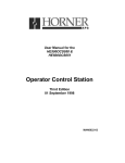
Figure 3.1 – 24V Operation from
External 24V Supply through
Terminal Connector
JP4
24V
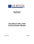
JP4
S90
The power select jumper JP4, a four-pin jumper located on the multiplexer circuit board near the power
connector, selects between 24VDC and 5VDC operation. To gain access to the jumper, remove the four
screws on the rear cover plate and remove the plate. Do not remove the top cover of the multiplexer!
The jumper configuration is as follows:
Figure 3.2 – 5V Operation from
Series 90 SNP Port through Pin
5 of Master Port
PAGE 16
CH. 3
29 NOV 2000
NOTES
MAN0080-02
MAN0080-02
29 NOV 2000
PAGE 17
CHAPTER 4: OPERATION
With the SNPM installation and configuration complete, the SNPM can now be powered-up. The SNPM
is equipped with two LED's, one near each slave port. At power-up, both LEDs will light during the SNPM
internal initialization and diagnostics. When both LEDs go out, the initialization sequence is complete.
The SNPM is then ready to accept SNP command messages through the slave ports.
During operation, the LEDs are used to indicate which of the slave ports is currently in control of the
master port. For example, if slave port #1 is given control of the master port, all SNP command data
received by slave port #2 is buffered. When slave port #1's SNP conversation is complete, slave port #1
releases control of the master port and slave port #2 is given control of the master port, the buffered
message is sent to the master port.
To gain a better understanding of the SNPM operation, a brief discussion of the SNP protocol is
necessary. SNP protocol is comprised of SNP messages. The SNP master device issues command
messages and the SNP slave devices return response messages. Each of these messages are relatively
short (usually 40 to 50 bytes each, but they can be as long as 8000 bytes). An SNP "conversation",
however, can consist of several command/response transactions, and cannot be interrupted. For
example, if slave port #1 were conducting a multi-message conversation with the Series 90 CPU
(perhaps doing a program load) and slave port #2 were to issue a request for reference table data, the
Series 90 CPU would confuse the data request for program information.
The SNPM is intelligent enough to recognize the end of an SNP conversation. A buffered command
message will not be sent to the master port until the current conversation is complete. There are,
however, some timing considerations to account for when using the SNPM. The SNP protocol has some
built-in timeouts. For example, if an SNP master does not receive a response to a command message
within a specified time limit, the master device will timeout and will attempt to re-establish the
communications link (most likely generating an error message on the user interface). This scenario,
although not serious, can be annoying if it occurs frequently.
Consider a situation where one slave port is configured for 300 baud, and the other is configured for
19200 baud. During a lengthy SNP conversation at 300 baud, a command message is received at 19200
baud and buffered. It is likely that the 19200 baud master device will timeout waiting for a response from
the slave because the amount of time required to complete the 300 baud conversation exceeds the SNP
timeout. The SNPM will yield better performance if both ports are configured for 1200 baud or higher.
Another anomaly surfaces when two SNP master devices are used and both devices set the privilege
level. For example, assume that the master device connected to slave port #1 logs on to the Series 90
and sets the privilege level to 3. After which the master device connected to slave port #2 logs on to the
Series 90 and sets the privilege level to 2. The first master might continue communicating while under
the impression that the Series 90 is still at privilege level 3. To avoid this problem, make sure that the
master device requiring the higher privilege level logs on last (allow the lower privilege level device to log
on, then invoke the higher privilege level device).
The SNP protocol is a complex protocol. The SNP Multiplexer, although complex in design, should prove
easy to implement into an end system and has been designed with ease of use in mind.
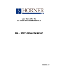
If the supplied cable is of insufficient length, the following cable can be constructed by the user.
PAGE 18
29 NOV 2000
Figure 4.1 – Cable Diagram
MAN0080-02