1
Introduction
SIMATIC FM 355 closed-loop control module
1
Product Overview
______________
SIMATIC
FM 355 closed-loop control module
Operating Instructions
Information for the controller
adjustment
2
______________
How Does the FM 355
Control?
3
______________
Installing and Removing the
FM 355
4
______________
Wiring the FM 355
5
Parameter Configuration of
the FM 355
6
Implementing the FM 355 in
the User Program
7
______________
______________
______________
8
Commissioning the FM 355
______________
Properties of Digital and
Analog Inputs and Outputs
9
______________
Connecting Measuring
Transducers and
Loads/Actuators
10
______________
Assignment of the Instance
DBs
11
______________
12
Faults and Diagnostics
______________
13
Examples
______________
This manual is part of the documentation package
with order no: 6ES7355-0VH00-8BA0
A
FB 29 and FB 30
______________
B
Data Sheet
______________
Edition 02/2006
A5E00059344-03
C
Spare Parts
______________
D
References
______________
Safety Guidelines
This manual contains notices you have to observe in order to ensure your personal safety, as well as to prevent
damage to property. The notices referring to your personal safety are highlighted in the manual by a safety alert
symbol, notices referring only to property damage have no safety alert symbol. These notices shown below are
graded according to the degree of danger.
Danger
indicates that death or severe personal injury will result if proper precautions are not taken.
Warning
indicates that death or severe personal injury may result if proper precautions are not taken.
Caution
with a safety alert symbol, indicates that minor personal injury can result if proper precautions are not taken.
Caution
without a safety alert symbol, indicates that property damage can result if proper precautions are not taken.
Notice
indicates that an unintended result or situation can occur if the corresponding information is not taken into
account.
If more than one degree of danger is present, the warning notice representing the highest degree of danger will
be used. A notice warning of injury to persons with a safety alert symbol may also include a warning relating to
property damage.
Qualified Personnel
The device/system may only be set up and used in conjunction with this documentation. Commissioning and
operation of a device/system may only be performed by qualified personnel. Within the context of the safety notes
in this documentation qualified persons are defined as persons who are authorized to commission, ground and
label devices, systems and circuits in accordance with established safety practices and standards.
Prescribed Usage
Note the following:
Warning
This device may only be used for the applications described in the catalog or the technical description and only in
connection with devices or components from other manufacturers which have been approved or recommended
by Siemens. Correct, reliable operation of the product requires proper transport, storage, positioning and
assembly as well as careful operation and maintenance.
Trademarks
All names identified by ® are registered trademarks of the Siemens AG. The remaining trademarks in this
publication may be trademarks whose use by third parties for their own purposes could violate the rights of the
owner.
Disclaimer of Liability
We have reviewed the contents of this publication to ensure consistency with the hardware and software
described. Since variance cannot be precluded entirely, we cannot guarantee full consistency. However, the
information in this publication is reviewed regularly and any necessary corrections are included in subsequent
editions.
Siemens AG
Automation and Drives
Postfach 48 48
90437 NÜRNBERG
GERMANY
Order No.: A5E00059344-03
Edition 02/2006
Copyright © Siemens AG 2006.
Technical data subject to change
Introduction
Preface
Purpose of This Manual
This manual describes all the steps that are required to use the FM 355 function module. It
supports rapid and effective familiarization with the FM 355 functionality.
Contents of the Manual
This manual describes the hardware and software of the FM 355. It consists of an instruction
section and contains reference material (appendices.)
The following subjects are covered:
• Fundamentals of controlling
• Installing and removing the FM 355
• Wiring the FM 355
• Assigning parameters to the FM 355
• Programming the FM 355
• Appendixes
Target Group
This manual is intended for the following target groups:
• Fitters
• Programmers
• Commissioning engineers
• Service and maintenance personnel
Scope of This Manual
The present manual contains the description of function module FM 355 applicable at the
time the manual was published. We reserve the right to describe changes of FM 355
functionality in a Product Information leaflet.
FM 355 closed-loop control module
Operating Instructions, Edition 02/2006, A5E00059344-03
iii
Introduction
Approvals
The S7-300 has the following approvals:
UL Recognition Mark
Underwriters Laboratories (UL) in accordance with Standard UL 508
CSA-Certification-Mark
Canadian Standard Association (CSA) to Standard C 22.2 No. 142
FM approval complying with Factory Mutual Approval Standard Class Number 3611, Class I,
Division 2, Group A, B, C, D
Warning
Personal injury and material damage may be incurred.
In potentially explosive environments, there is a risk of injury or damage if you disconnect
any connectors while the S7-300 is in operation.
Always isolate the S7-300 operated in such areas before you disconnect and connectors.
Warning
WARNING - DO NOT DISCONNECT WHILE CIRCUIT IS LIVE UNLESS LOCATION IS
KNOWN TO BE NONHAZARDOUS
CE Marking
Our products fulfill the requirements of the EU Directive 89/336/EEC ”Electromagnetic
compatibility”.
The EU conformity certificates are available for the relevant authorities and are kept at the
following address in accordance with the above-mentioned EU Directive. Article 10:
Siemens Aktiengesellschaft
Bereich Automatisierungs- und Antriebstechnik
A&D AS RD ST PLC
Postfach 1963
D-92209 Amberg
iv
FM 355 closed-loop control module
Operating Instructions, Edition 02/2006, A5E00059344-03
Introduction
Position in the Information Landscape
This manual is a component of the S7-300 and ET 200M documentation.
System
S7-300
Documentation
•
•
•
ET 200M
•
•
S7-300 Automation systems
Structure, CPU Data
S7-300, M7-300 Automation systems, Module specifications
S7-300 Operation List
ET 200M Distributed I/O Device
S7-300, M7-300 Automation systems, Module Specifications
Guide
The manual contains the following guides which provide quick access to the specific
information you need:
• At the beginning of the manual you can find a comprehensive list of contents.
• Following the appendices, you will find a glossary in which important technical terms used
in the manual are defined.
• The manual closes with a list of references and a detailed index for quick access to the
information you require.
Further Support
If you have any questions concerning the use of products which are not answered in this
manual, please contact your local Siemens partner at your Siemens office. A list of Siemens
representatives worldwide is contained, for example, in the appendix entitled "Siemens
Worldwide" of the manual "S7-300 Automation systems, Configuration of an S7-300.
We offer a range of courses to help get you started with the SIMATIC S7 programmable
controller. Please contact your local training center or the central training center in
Nuremberg, D-90327 Germany, Tel. +49 (0) 911 895 3200.
FM 355 closed-loop control module
Operating Instructions, Edition 02/2006, A5E00059344-03
v
Introduction
Up-to-the-minute Information
The SIMATIC Customer Support offers you extensive additional information on the SIMATIC
products via the on-line services:
• You can obtain general current information:
– On the Internet at http://www.ad.siemens.de/simatic
• Current product information and downloads as an additional help:
– On the Internet at http://www.ad.siemens.de/simatic-cs
– Via the Bulletin Board System (BBS) in Nuremberg
(SIMATIC Customer Support Mailbox) under +49 (911) 895-7100.
To dial the mailbox, use a modem with up to V.34 (28.8 Kbps), with the following
parameter settings: 8, N, 1, ANSI, or dial via ISDN (x.75, 64 Kbps).
Nuremberg
SIMATIC BASIC Hotline
Johnson City
SIMATIC BASIC Hotline
Singapore
SIMATIC BASIC Hotline
Local time: M - F 7:00 a.m. to 5:00 p.m. Local time: M - F 8:00 a.m. to 5:00 p.m. Local time: Mo.-Fr. 8:30 to 17:30
Phone: +49 (180) 5050-222
Phone: +1 423 461-2522
Phone: +65 740-7000
Fax: +49 (180) 5050-223
Fax: +1 423 461-2231
Fax: +65 740-7001
Email: techsupport@
Email: simatic.hotline@
Email: simatic.hotline@
ad.siemens.de
sea.siemens.com
sae.siemens.com.sg
GMT: +1:00
GMT: –5:00
GMT: +8:00
Nuremberg
SIMATIC Premium Hotline
SIMATIC authorization hotline
(fee based, only with SIMATIC Card)
Local time: M - F 7:00 a.m. to 5:00 p.m. Time: Mon.-Fri. 0:00 to 24:00
Phone: +49 (911) 895-7200
Phone: +49 (911) 895-7777
Fax: +49 (911) 895-7201
Fax: +49 (911) 895-7001
Email: authorization@
nbgm.siemens.de
GMT: +1:00
GMT: +1:00
The languages of the SIMATIC Hotlines are generally German and English, in addition, French, Italian and Spanish are
spoken on the authorization hotline.
vi
FM 355 closed-loop control module
Operating Instructions, Edition 02/2006, A5E00059344-03
Table of contents
Introduction................................................................................................................................................ iii
1
2
3
4
Product Overview ................................................................................................................................... 1-1
1.1
Introduction ................................................................................................................................ 1-1
1.2
Functionality of the FM 355........................................................................................................ 1-2
1.3
Areas of Application for the FM 355 .......................................................................................... 1-4
1.4
FM 355 Hardware ...................................................................................................................... 1-5
1.5
FM 355 Software........................................................................................................................ 1-8
Information for the controller adjustment................................................................................................. 2-1
2.1
Characteristic Values of the Controlled System ........................................................................ 2-1
2.2
Controller Types (Two-Step, Three-Step Controllers) ............................................................... 2-4
2.3
Control Response at Different Feedback Structures ................................................................. 2-7
2.4
Choosing the controller structure with a given control section ................................................ 2-14
2.5
Setting the Controller Characteristic Values (Optimization) .................................................... 2-16
2.6
Determining the System Parameters for Two-/Three-Step Controllers ................................... 2-18
2.7
Determining the System Parameters for Pure Cooling Controllers ......................................... 2-21
2.8
Establishing parameters by experiment................................................................................... 2-23
How Does the FM 355 Control?.............................................................................................................. 3-1
3.1
Basic Structure of the FM 355 ................................................................................................... 3-1
3.2
Basic Parameters....................................................................................................................... 3-4
3.3
3.3.1
3.3.2
FM 355 inputs ............................................................................................................................ 3-4
Analog inputs ............................................................................................................................. 3-5
Digital Inputs .............................................................................................................................. 3-7
3.4
Controller.................................................................................................................................... 3-8
3.5
Outputs of the FM 355 ............................................................................................................. 3-28
3.6
Functional mechanisms and data storage in the FM 355........................................................ 3-30
3.7
Characteristics of the FM 355 .................................................................................................. 3-35
3.8
Parameter optimization with temperature controllers .............................................................. 3-41
Installing and Removing the FM 355....................................................................................................... 4-1
4.1
Preparing for Installation ............................................................................................................ 4-1
4.2
Installing and Removing the FM 355 ......................................................................................... 4-3
FM 355 closed-loop control module
Operating Instructions, Edition 02/2006, A5E00059344-03
vii
Table of contents
5
6
7
Wiring the FM 355 .................................................................................................................................. 5-1
5.1
Terminal assignment of the front connectors............................................................................. 5-1
5.2
Wiring front connectors .............................................................................................................. 5-8
5.3
Module Status After First Being Switched On.......................................................................... 5-10
Parameter Configuration of the FM 355.................................................................................................. 6-1
6.1
Installing the Parameterization Interface.................................................................................... 6-1
6.2
Configuring the hardware........................................................................................................... 6-2
6.3
Parameter assignment ............................................................................................................... 6-2
Implementing the FM 355 in the User Program ...................................................................................... 7-1
7.1
Summary .................................................................................................................................... 7-1
7.2
7.2.1
7.2.2
7.2.3
7.2.4
7.2.5
7.2.6
The function block PID_FM ........................................................................................................ 7-2
Operator Control via the PID_FM FB ......................................................................................... 7-3
Monitoring via the PID_FM FB ................................................................................................... 7-3
Changing Controller Parameters Using the PID_FM FB ........................................................... 7-5
Changing controller parameters via the OP............................................................................... 7-6
Saving the parameters in EEPROM .......................................................................................... 7-7
Relationship between FB parameters and the parameterization interface................................ 7-7
7.3
The FUZ_355 function block .................................................................................................... 7-14
7.4
The FORCE355 function block ................................................................................................ 7-16
7.5
The READ_355 function block ................................................................................................. 7-18
7.6
The CH_DIAG function block ................................................................................................... 7-20
7.7
The PID_PAR function block.................................................................................................... 7-23
7.8
The CJ_T_PAR Function Block................................................................................................ 7-29
7.9
PROFINET Operation .............................................................................................................. 7-31
8
Commissioning the FM 355 .................................................................................................................... 8-1
9
Properties of Digital and Analog Inputs and Outputs .............................................................................. 9-1
10
11
viii
9.1
Properties of the Digital Inputs and Outputs (Step Controllers)................................................. 9-1
9.2
Properties of the Analog Inputs.................................................................................................. 9-3
9.3
Properties of the Analog Outputs (Continuous-Action Controllers) ........................................... 9-6
Connecting Measuring Transducers and Loads/Actuators.................................................................... 10-1
10.1
Connecting Measuring Transducers to Analog Inputs............................................................. 10-1
10.2
Use of Thermocouples ............................................................................................................. 10-5
10.3
Connecting Voltage Sensors, Current Sensors and Resistance Thermometers................... 10-10
10.4
Connecting Loads/Actuators to Analog Outputs.................................................................... 10-13
10.5
Connecting Loads/Actuators to Digital Outputs ..................................................................... 10-15
Assignment of the Instance DBs........................................................................................................... 11-1
11.1
Instance DB of the PID_FM FB ................................................................................................ 11-1
11.2
Instance DB of the FUZ_355 FB ............................................................................................ 11-20
11.3
Instance DB of the FB FORCE355 ........................................................................................ 11-23
FM 355 closed-loop control module
Operating Instructions, Edition 02/2006, A5E00059344-03
Table of contents
12
13
A
B
C
11.4
Instance DB of the READ_355 FB......................................................................................... 11-26
11.5
Instance DB of the CH_DIAG FB ........................................................................................... 11-28
11.6
Instance DB of the PID_PAR FB............................................................................................ 11-31
11.7
Instance DB of the CJ_T_PAR FB ......................................................................................... 11-33
11.8
Assignment of the DBs for Operator Control and Monitoring via OP .................................... 11-35
Faults and Diagnostics ......................................................................................................................... 12-1
12.1
Error display from the group error
12.2
Triggering diagnostic interrupts................................................................................................ 12-2
12.3
Measuring transformer error .................................................................................................... 12-6
Examples.............................................................................................................................................. 13-1
13.1
Application example for the FM 355 S..................................................................................... 13-1
13.2
Application example for the FM 355 C..................................................................................... 13-6
13.3
Application Example for Diagnostics ..................................................................................... 13-10
13.4
Interconnection example for a cascade control ..................................................................... 13-11
13.5
Interconnection example for a ratio control............................................................................ 13-12
13.6
Interconnection example for a mixed control ......................................................................... 13-13
FB 29 and FB 30.....................................................................................................................................A-1
A.1
The FB 29 "PID_PAR" function block ........................................................................................ A-1
A.2
Instance DB of the FB 29 .......................................................................................................... A-7
A.3
The FB 30 "CJ_T_PAR" function block .................................................................................... A-10
A.4
Instance DB of the FB 30 ........................................................................................................ A-12
A.5
List of RET_VALU messages................................................................................................... A-15
Data Sheet..............................................................................................................................................B-1
B.1
Technical Specifications S7-300................................................................................................ B-1
B.2
Technical Specifications FM 355 ............................................................................................... B-3
B.3
Technical Specifications of Function Blocks.............................................................................. B-9
B.4
Technical Data of Parameter Configuration Interface.............................................................. B-10
Spare Parts.............................................................................................................................................C-1
C.1
D
LED ................................................................................ 12-1
Spare Parts ................................................................................................................................C-1
References .............................................................................................................................................D-1
D.1
References.................................................................................................................................D-1
Glossary ..................................................................................................................................... Glossary-1
Index................................................................................................................................................ Index-1
FM 355 closed-loop control module
Operating Instructions, Edition 02/2006, A5E00059344-03
ix
Table of contents
Tables
Table 1-1
Inputs and outputs of the the FM 355 ........................................................................................ 1-3
Table 1-2
Diagnostics and Status LED's.................................................................................................... 1-7
Table 2-1
Suitable Controller for the Most Important Control Variables .................................................. 2-15
Table 3-1
Signal selection for setpoint value, D-action input and disturbance variable........................... 3-13
Table 3-2
Functions of the controller output and setting possibilities ...................................................... 3-26
Table 3-3
Assignment and meaning of the digital outputs ....................................................................... 3-29
Table 3-4
Conversion time of an analog input ......................................................................................... 3-36
Table 3-5
Rules for the conversion time .................................................................................................. 3-36
Table 5-1
Terminal assignment of the front connectors of the FM 355 C.................................................. 5-2
Table 5-2
Terminal assignment of the front connectors of the FM 355 S .................................................. 5-4
Table 7-1
List of the REAL and INT parameters that can be changed with the PID_PAR FB................. 7-25
Table 7-2
List of the CPUs, in which the PID_PAR FB can be used ....................................................... 7-28
Table 11-1
Input parameters of the instance DB for the PID_FM FB ........................................................ 11-2
Table 11-2
Output parameters of the instance DB for the PID_FM FB...................................................... 11-3
Table 11-3
I/O parameters of the instance DB for the PID_FM FB.......................................................... 11-11
Table 11-4
Input parameters of the instance DB for the FUZ_355 FB..................................................... 11-21
Table 11-5
Output parameters of the instance DB for the FUZ_355 FB.................................................. 11-21
Table 11-6
Input parameters of the instance DB for the FORCE355 FB................................................. 11-23
Table 11-7
Output parameters of the instance DB to the FB FORCE355 ............................................... 11-25
Table 11-8
Input parameters of the instance DB for the READ_355 FB.................................................. 11-26
Table 11-9
Output parameters of the instance DB for the READ_355 FB............................................... 11-26
Table 11-10
Input parameters of the instance DB for the CH_DIAG FB.................................................... 11-28
Table 11-11
Output parameters of the instance DB for the CH_DIAG FB................................................. 11-30
Table 11-12
Input parameters of the instance DB for the PID_PAR FB .................................................... 11-31
Table 11-13
Output parameters of the instance DB for the PID_PAR FB ................................................. 11-32
Table 11-14
Input parameters of the instance DB for the CJ_T_PAR FB.................................................. 11-33
Table 11-15
Output parameters of the instance DB for the CJ_T_PAR FB ............................................... 11-34
Table 11-16
Input parameters of the DBs for operator control and monitoring.......................................... 11-35
Table 11-17
Output parameters of the DBs for operator control and monitoring....................................... 11-43
Table 11-18
I/O parameters of the DBs for operator control and monitoring............................................. 11-51
Table 12-1
Assignments of diagnostics record DS0 .................................................................................. 12-3
Table 12-2
Assignment of Bytes 4 to 12 of the diagnostics record DS1.................................................... 12-4
Table 13-1
Blocks of Example 1................................................................................................................. 13-3
Table 13-2
Blocks of Example 2................................................................................................................. 13-7
Table A-1
List of the REAL and INT parameters that can be changed with the "PID_PAR" FB ................A-3
Table A-2
Input parameters of the instance DB for the FB 29 "'PID_PAR" ................................................A-7
x
FM 355 closed-loop control module
Operating Instructions, Edition 02/2006, A5E00059344-03
Table of contents
Table A-3
Input parameters of the instance DB for the FB 29 "'PID_PAR"................................................ A-8
Table A-4
Through parameters of the instance DB for the FB 29 "'PID_PAR" .......................................... A-9
Table A-5
Input parameters of the instance DB for the FB 30 "CJ_T_PAR" ............................................ A-12
Table A-6
Output parameters of the instance DB for the FB 30 "CJ_T_PAR" ......................................... A-13
Table A-7
Through parameters of the instance DB for the FB 30 "CJ_T_PAR"....................................... A-14
Table B-1
Technical specifications of the function blocks .......................................................................... B-9
Table B-2
Processing times of the PID_FM at various conditions.............................................................. B-9
Table B-3
Technical specifications of the instance DBs............................................................................. B-9
Table C-1
Accessories and spare parts......................................................................................................C-1
FM 355 closed-loop control module
Operating Instructions, Edition 02/2006, A5E00059344-03
xi
Table of contents
xii
FM 355 closed-loop control module
Operating Instructions, Edition 02/2006, A5E00059344-03
1
Product Overview
1.1
1.1
Introduction
Variants of the FM 355
The FM 355 is available in the following 2 variants:
• Continuous-action controller with analog outputs
• S controller (step and pulse controllers with digital outputs)
Order Numbers
Product
FM 355 C
Scope of delivery
•
•
FM 355 S
•
•
Order Number
FM 355 C module, version ≥ 6 (continuous
controller)
CD with configuration package, manual and
Getting Started
6ES7355-0VH10-0AE0
FM 355 S module, version ≥ 6 (step and pulse
controller)
CD with configuration package, manual and
Getting Started
6ES7355-1VH10-0AE0
FM 355 closed-loop control module
Operating Instructions, Edition 02/2006, A5E00059344-03
1-1
Product Overview
1.2 Functionality of the FM 355
1.2
1.2
Functionality of the FM 355
Introduction
The FM 355 function module is a controller module for use in the S7-300 Automation
systems.
Control Method
Two different control methods are implemented in the FM 355. Support in optimizing the
control system is available for both control methods:
Control method
Optimization by ...
Temperature controller (fuzzy controller)
... The module (self-tuning controller)
PID controller
... Parameter assignment interface or PID Self Tuner
Control Structures
You can use the FM 355 for the following control structures:
• Set-value control
• Follower control
• 3-component control
• Cascade control
• Ratio control
• Mix control
• Split-range control
Operating modes
The FM 355 can operate in the following modes:
• Automatic
• Manual
• Safety mode
• Follow-up control mode (changeover to preset safety value)
• Specification of the manipulated value DDC (Direct Digital Control)
• Follow-up/SPC controller (SPC = Set Point Control)
• Back-up mode (at CPU in STOP or CPU failure)
1-2
FM 355 closed-loop control module
Operating Instructions, Edition 02/2006, A5E00059344-03
Product Overview
1.2 Functionality of the FM 355
Number of Channels
The FM 355 contains 4 controllers operating independently of each other in 4 channels.
Number of Inputs and Outputs
The following table provides an overview of the number of inputs and outputs of the FM 355.
Table 1-1
Inputs and outputs of the the FM 355
Inputs/Outputs
FM 355 C
FM 355 S
Analog inputs
4
4
Digital inputs
8
8
Analog outputs
4
-
Digital outputs
-
8
Diagnostics Interrupt
The FM 355 can trigger a diagnostics interrupt if any of the following occur:
• Error in module parameterization
• Module defective
• Overflow and underflow at analog inputs
• Load break and short circuit at analog outputs
Hardware Interrupts
Hardware interrupts are not required for FM 355 operation.
Reference Junction
For operation with thermocouples the FM 355 has an additional analog input for connecting
a Pt100 in 4-wire design. This input is used to measure the reference junction temperature
and thus to carry out compensation at thermocouples.
Parameterization
The FM 355 can be parameterized by means of a parameter configuration interface.
FM 355 closed-loop control module
Operating Instructions, Edition 02/2006, A5E00059344-03
1-3
Product Overview
1.3 Areas of Application for the FM 355
1.3
1.3
Areas of Application for the FM 355
Where Can You Use the FM 355?
The FM 355 is a universally applicable controller module for the following control tasks:
• Temperature control
• Level control
• Filling level control
• Pressure control
• Flow control
• Concentration control
Applications
The FM 355 is usually used to carry out control tasks in the following branches:
• General machine construction
• Plant construction
• Industrial furnace construction
• Cooling and heating unit construction
• Food and beverage industry
• Process engineering
• Environmental technology
• Glass and ceramics manufacturing
• Rubber and plastics machines
• Woodworking and paper industry
1-4
FM 355 closed-loop control module
Operating Instructions, Edition 02/2006, A5E00059344-03
Product Overview
1.4 FM 355 Hardware
1.4
1.4
FM 355 Hardware
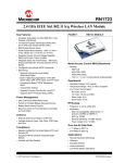
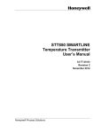
Module View
The following figure shows the FM 355 module with front connectors and the bus connector
at closed front doors.
Figure 1-1
;
FM 355 module view
①
Front connector with front connector coding
②
Type plate
③
SIMATIC interface bus connector
④
Version
⑤
Order Number
⑥
Labeling strips
⑦
LEDs
FM 355 closed-loop control module
Operating Instructions, Edition 02/2006, A5E00059344-03
1-5
Product Overview
1.4 FM 355 Hardware
Front Connectors
The FM 355 offers the following connection possibilities via the front connectors:
• 8 digital inputs
• 4 analog inputs
• 1 reference junction input
• 8 digital outputs (only step controllers)
• 4 analog outputs (only continuous-action controllers)
• Supply voltage 24 V DC between L+ and M to supply the module and the digital and
analog outputs
• Reference point of the analog circuit MANA
The front connectors must be ordered separately (refer to the "Spare Parts" appendix).
Front Connector Coding
When you press a front connector from the wiring position to the operating position, the front
connector coding engages. Thereafter, this front connector can only be attached to an FM
355 module.
Labeling strips
Enclosed with the module are two labeling strip on which you can write your signal names
individually.
The corresponding pin assignments are printed on the insides of the front panel.
Order Number and Version
The order number and the version of the FM 355 are given at the bottom of the left-hand
front panel.
Bus Connectors
The communication within a row of the S7 300 takes place via the bus connector. The bus
connector is enclosed with the FM 355.
1-6
FM 355 closed-loop control module
Operating Instructions, Edition 02/2006, A5E00059344-03
Product Overview
1.4 FM 355 Hardware
Diagnostics and Status LED's
The FM 355 has ten LEDs that can be used both for diagnostics and for indicating the status
of the FM 355 and its digital inputs.
The following table lists the LEDs with their labeling, color and function.
Table 1-2
Diagnostics and Status LED's
Labeling
Color
Function
SF
red
Group error
Backup
Yellow
Display of the backup mode
I1
Green
Status of Digital Input I1
I2
Green
Status of Digital Input I2
I3
Green
Status of Digital Input I3
I4
Green
Status of Digital Input I4
I5
Green
Status of Digital Input I5
I6
Green
Status of Digital Input I6
I7
Green
Status of Digital Input I7
I8
Green
Status of Digital Input I8
The LEDs next to the binary outputs of the FM 355 S are not controlled and do not have any
meaning.
FM 355 closed-loop control module
Operating Instructions, Edition 02/2006, A5E00059344-03
1-7
Product Overview
1.5 FM 355 Software
1.5
1.5
FM 355 Software
Software Package of the FM 355
In order to integrate the FM 355 in the S7-300 you require a software package with:
• Parameter configuration interface
• Software for the CPU (function blocks)
Parameter Configuration Interface
The FM 355 is adapted to the task in hand via parameters. These parameters are stored in
the system data and are transferred in the CPU STOP state from the programming
device/PC to the CPU and to the FM 355. In addition the CPU transfers these parameters to
the module during every transition from STOP to RUN.
You can specify the parameters via the parameter configuration interface. The parameter
configuration interface is installed on your programming device/PC and called up within
STEP 7.
Online Help
Further information about the parameter configuration is available in the integrated online
help.
Software for the S7-300 CPU (Function Blocks)
The software for the CPU consists of the function blocks:
• PID_FM for modifying parameters and operating modes (e.g. setpoint, manual to
automatic changeover) during running operation and to read out process states (e.g.
actual value).
• FORCE355 for forcing analog and digital inputs during commissioning (forcing = specify
simulation values).
• READ_355 for reading out the analog and digital input values during commissioning.
• CH_DIAG for reading out channel-specific diagnostic values during commissioning.
• FUZ_355 for reading out the parameters of the self-tuning temperature controller (fuzzy
controller) for loading these parameters to the FM 355 (e.g. at a module replacement
without renewed parameter identification of the controller).
• PID_PAR for special applications for changing further parameters during running
operation.
1-8
FM 355 closed-loop control module
Operating Instructions, Edition 02/2006, A5E00059344-03
Product Overview
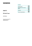
1.5 FM 355 Software
The following figure shows an S7-300 configuration with an FM 355 and several signal
modules.
Figure 1-2
SIMATIC S7-300 configuration with an FM 355
①
Programming device (PG) with STEP 7 and the parameter configuration masks
②
FM 355
③
CPU with application program and FBs of the FM 355
FM 355 closed-loop control module
Operating Instructions, Edition 02/2006, A5E00059344-03
1-9
Product Overview
1.5 FM 355 Software
1-10
FM 355 closed-loop control module
Operating Instructions, Edition 02/2006, A5E00059344-03
2
Information for the controller adjustment
2.1
2.1
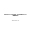
Characteristic Values of the Controlled System
Determining the Time Response from the Step Response
Time response of the controlled system can be determined by the time sequence of
Controlled variable x after an abrupt change of Manipulated variable y from 0 to 100%.
\
<K
.V
; PD[
<K
W
FM 355 closed-loop control module
Operating Instructions, Edition 02/2006, A5E00059344-03
2-1
Information for the controller adjustment
2.1 Characteristic Values of the Controlled System
[
7J
; PD[
;K
ෙ[
.V
ෙW
W
7X
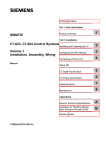
Figure 2-1
Step response of a controlled system
①
100% ON
②
0% OFF
Most of the controlled systems are so-called controlled systems with self-regulation (refer to
the figure above).
The time response can be determined by approximation using the variables Delay time Tu,
Recovery time Tg and Maximum value Xmax. The variables are determined by applying
tangents to the maximum value and the inflection point of the step response. Recording the
transition function up to the maximum value is not possible in many cases because the
controlled variable may not exceed certain values. The rate of rise vmax is therefore used for
the controlled system.
From the ratio
Tu / Tg or Tu x vmax / Xmax
it is possible to estimate the suitability of the controlled system for controlling. The following
applies:
Tu / T g
Suitability of the controlled system for controlling
< 0,1
can be controlled well
0.1 to 0.3
can still be controlled
> 0,3
difficult to control
Controlled systems can be judged on the basis of the following values:
Tu < 0.5 min, Tg < 5 min = fast controlled system
Tu > 0.5 min, Tg > 5 min = slow controlled system
2-2
FM 355 closed-loop control module
Operating Instructions, Edition 02/2006, A5E00059344-03
Information for the controller adjustment
2.1 Characteristic Values of the Controlled System
Characteristic values of important temperature controlled systems
Controlled
variable
Temperature
Type of controlled system
Delay time Tu
Recovery time Tg
Rate of rise vmax
Small electrically heated furnace
0.5 to 1 min
5 to 15 min
Up to 60 K/min.
Large electrically heated annealing
furnace
1 to 5 min
10 to 20 min
Up to 20 K/min.
Large gas-heated annealing furnace
0.2 to 5 min
3 to 60 min
1 to 30 K/min
Autoclaves
0.5 to 0.7 min
10 to 20 min
High-pressure autoclaves
12 to 15 min
200 to 300 min
Injection molding machines
0.5 to 3 min
3 to 30 min
Extruders
1 to 6 min
5 to 60 min
Packaging machines
0.5 to 4 min
3 to 40 min
FM 355 closed-loop control module
Operating Instructions, Edition 02/2006, A5E00059344-03
5 to 20 K/min
2 to 35 K/min
2-3
Information for the controller adjustment
2.2 Controller Types (Two-Step, Three-Step Controllers)
2.2
2.2
Controller Types (Two-Step, Three-Step Controllers)
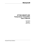
Two-Step Controllers Without Feedback
Two-step controllers have the state "ON" and "OFF" as the switching function. This
corresponds to 100% or 0% output. Through this behavior a sustained oscillation of
Controlled variable x occurs around Setpoint value w.
The amplitude and the oscillation duration increases with the ratio of the Delay time Tu to the
Recovery time Tg of the controlled system. These controllers are used mainly for simple
temperature control systems (such as electrically directly heated furnaces) or as limit-value
signaling units.
\
<K
[
Z
Figure 2-2
2-4
Characteristic curve of a two-step controller
①
ON
②
OFF
Yh
Position range
w
Reference value
FM 355 closed-loop control module
Operating Instructions, Edition 02/2006, A5E00059344-03
Information for the controller adjustment
2.2 Controller Types (Two-Step, Three-Step Controllers)
[
7J
Z
; 6G
7X
W
\
W
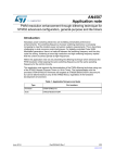
Figure 2-3
Control function of a two-step controller without feedback
①
Transition function without controller
Tu
Delay time
Tg
Recovery time
XSd
Switching difference
Two-Step Controllers With Feedback
The behavior of two-step controllers at controlled systems with high delay times, e.g.
furnaces at which the utilization room is separated from the heating, can be improved
through electronic feedbacks.
The feedback is used to increase the switching frequency of the controller, thus reducing the
amplitude of the controlled variable. In addition, the control-action results can be improved
substantially in dynamic operation. The limit for the switching frequency is set by the output
level. It should not exceed 1 to 5 switches per minute at mechanical actuators, such as
relays and contactors. In the case of voltage and current outputs with downstream thyristor
or Triac controllers high switching frequencies can be selected that exceed the limit
frequency of the controlled system by far.
FM 355 closed-loop control module
Operating Instructions, Edition 02/2006, A5E00059344-03
2-5
Information for the controller adjustment
2.2 Controller Types (Two-Step, Three-Step Controllers)
Since the switching pulses can no longer be determined at the output of the controlled
system, results comparable with those of continuous controllers are obtained.
In contrast to a continuous controller, at which the amplitude of the output signal represents
the manipulated variable, the output variable is formed at a two-step controller with feedback
through pulse width modulation.
Two-step controllers with feedback are used for temperature control in furnaces, at
processing machines in the plastics, textile, paper, rubber and foodstuff industries as well as
for heating and cooling devices.
Three-Step Controllers
Three-step controllers are used for heating/cooling. These controllers have 2 switching
points as their output. The control-action results are optimized through electronic feedback
structures. Fields of applications for such controllers are heating, low-temperature, climatic
chambers and tool heating units for plastic-processing machines.
\
\ \ \ \ [
Z
[ 6K
Figure 2-4
y
Characteristic curve of a three-step controller
Manipulated variable, e.g.
y11 = 100% heating
y12 = 0% heating
y21 = 0% cooling
y22 = 100% cooling
x
2-6
Controlled variable, e.g. temperature in °C
w
Setpoint
xSh
Distance between Switching Point 1 and Switching Point 2
FM 355 closed-loop control module
Operating Instructions, Edition 02/2006, A5E00059344-03
Information for the controller adjustment
2.3 Control Response at Different Feedback Structures
2.3
2.3
Control Response at Different Feedback Structures
Control Behavior of Controllers
In order to achieve the precision of a control system and optimal disturbance correction an
adaptation of the controller to the time response of the controlled system is required.
Feedback structures are used to this purpose. Depending on the feedback circuit structure
this can have a proportional action (P), proportional-derivative action (PD), proportionalintegral action (PI) or proportional-integral-derivative action (PID). If a jump function to the
controller input exists, jump responses arise under the condition that the delay times of the
controller are negligibly small and that the controller reacts very rapidly.
P-action Controller
[
6WHSIXQFWLRQRQWKH
FRQWUROOHULQSXW
,QSXWYDULDEOH
W
\
6WHSUHVSRQVHRIWKH
FRQWLQXRXVFRQWUROOHU
2XWSXWYDULDEOH
W
\
6WHSUHVSRQVHRIWKH
SXOVHFRQWUROOHU
2XWSXWYDULDEOH
Figure 2-5
W
The jump response of a P-action controller
FM 355 closed-loop control module
Operating Instructions, Edition 02/2006, A5E00059344-03
2-7
Information for the controller adjustment
2.3 Control Response at Different Feedback Structures
Equation for P-action controller
Output variable and input variable are directly proportional, meaning:
Output variable change = Proportional-action gain x Input variable change, or
y = GAIN x xw
PD-action controller
[
6WHSIXQFWLRQRQWKH
FRQWUROOHULQSXW
W
,QSXWYDULDEOH
\
6WHSUHVSRQVHRIWKH
FRQWLQXRXVFRQWUROOHU
70B/$*
2XWSXWYDULDEOH
W
\
6WHSUHVSRQVHRIWKH
SXOVHFRQWUROOHU
Figure 2-6
2XWSXWYDULDEOH
W
Jump response of a PD-action controller
D-action control elements are not suitable on their for controlling, since they no longer emit
an actuating command when the input variable has settled back to a static value.
In combination with P-action control elements the derivative component is used to generate
a corresponding control pulse depending on the change speed of the controlled variable
2-8
FM 355 closed-loop control module
Operating Instructions, Edition 02/2006, A5E00059344-03
Information for the controller adjustment
2.3 Control Response at Different Feedback Structures
If a Disturbance x acts on the controlled system, the PD-action controller sets a different
system deviation due to the changed degree of correction. Disturbances are not corrected
completely. The good dynamic response is advantageous. A well attenuated, non-oscillating
transition is achieved during starting up and the reference input variable. However, a
controller with D-action is not appropriate if a controlled system has pulsing measured
quantities, for example at pressure or flow control systems.
Equation for PD-action controller
The following applies for the jump response of the PD-action controller in the time range:
\
*$,1[ Z
7'
70B/$*
H
ದW
70B/$*
t = Duration since the jump of the input variable
FM 355 closed-loop control module
Operating Instructions, Edition 02/2006, A5E00059344-03
2-9
Information for the controller adjustment
2.3 Control Response at Different Feedback Structures
PI-action Controller
[
6WHSIXQFWLRQRQWKH
FRQWUROOHULQSXW
,QSXWYDULDEOH
W
\
6WHSUHVSRQVHRIWKH
FRQWLQXRXVFRQWUROOHU
2XWSXWYDULDEOH
W
\
6WHSUHVSRQVHRIWKH
SXOVHFRQWUROOHU
2XWSXWYDULDEOH
Figure 2-7
W
Jump response of a PI-action controller
I-action control elements have the integral of the input variable as the output variable, i.e. the
controller totals the deviation from the setpoint value for the duration. This means that the
controller continues to adjust until the deviation from the setpoint value has been eliminated.
In practical experience a combination of the various timing elements is ideal, depending on
the requirements placed on the control response. The time response of the individual
elements can be described by the controller parameters Proportional band GAIN, Reset time
TI (I-action) and Differential-action time TD (D-action).
2-10
FM 355 closed-loop control module
Operating Instructions, Edition 02/2006, A5E00059344-03
Information for the controller adjustment
2.3 Control Response at Different Feedback Structures
Equation for PI-action controller
The following applies for the jump response of the PI-action controller in the time range:
\
*$,1[ Z
7, W
t = Duration since the jump of the input variable
FM 355 closed-loop control module
Operating Instructions, Edition 02/2006, A5E00059344-03
2-11
Information for the controller adjustment
2.3 Control Response at Different Feedback Structures
PID-action Controller
[
6WHSIXQFWLRQRQWKH
FRQWUROOHULQSXW
,QSXWYDULDEOH
W
\
6WHSUHVSRQVHRIWKH
FRQWLQXRXVFRQWUROOHU
70B/$*
2XWSXWYDULDEOH
W
0Q
\
6WHSUHVSRQVHRIWKH
SXOVHFRQWUROOHU
2XWSXWYDULDEOH
Figure 2-8
2-12
W
Jump response of a PID-action controller
FM 355 closed-loop control module
Operating Instructions, Edition 02/2006, A5E00059344-03
Information for the controller adjustment
2.3 Control Response at Different Feedback Structures
Most of the controller systems occurring in process engineering can be controlled by means
of a controller with PI-action response. In case of slow controlled systems with a high delay
time, for example temperature control systems, the control-action results can be improved by
a controller with PID action.
[
8QLWVWHSUHVSRQVH
ZLWKRXWFRQWUROOHU
3,'
Z
3'
W
Figure 2-9
Jump response at various control responses
Controllers with PI and PID action have the advantage that the controlled variable does not
have any deviation from the setpoint value after settling. The controlled variable oscillates
over the setpoint value during starting up.
Equation for PID-action controller
The following applies for the jump response of the PI-action controller in the time range:
\
*$,1[ Z
7, W
7'
70B/$*
H
ದW
70B/$*
t = Duration since the jump of the input variable
FM 355 closed-loop control module
Operating Instructions, Edition 02/2006, A5E00059344-03
2-13
Information for the controller adjustment
2.4 Choosing the controller structure with a given control section
2.4
2.4
Choosing the controller structure with a given control section
Selection of the Suitable Controller Structures
Amongst the closed-control elements the controlled systems have a special position. Their
properties are determined by the process-specific applications and cannot be changed
afterwards. An optimal control-action result can thus only be achieved by the selection of a
suitable controller whose response can be adapted to the system data within certain limits.
Controlled system
Controller structure
P
2-14
PD
PI
PID
Pure dead time
Unusable
Unusable
Control
+ disturbance
Unusable
Dead time
+ first-order
time-delay
Unusable
Unusable
Slightly worse
than PID
Control
+ disturbance
Dead time
+ second-order
time-delay
Not suitable
Bad
Worse than PID
Control
+ disturbance
Order
+ very small dead time
(delay time)
Control
Control at delay
time
Disturbance
Disturbance at
delay time
Higher order
Not suitable
Not suitable
Slightly worse
than PID
Control
+ disturbance
Not self-regulating
Control (without
delay)
Control (with delay)
Control (without
delay)
Control (with
delay)
FM 355 closed-loop control module
Operating Instructions, Edition 02/2006, A5E00059344-03
Information for the controller adjustment
2.4 Choosing the controller structure with a given control section
Table 2-1
Suitable Controller for the Most Important Control Variables
Controller
Controlled variable
P
PD
Steady-state control deviation
PI
PID
No steady-state control deviation
Temperature
for less demands
and with P
sections with Tu /
Tg < 0.1
Well suited
The most suitable controller types for
high-quality requirements (except for
specially adapted special controllers)
Pressure
Suitable, if the
delay time is
inconsiderable
Unsuitable
The most suitable controller types for
high-quality requirements (except for
specially adapted special controllers)
Flow rate
If suitable,
because required
GAIN range
usually too large
Unsuitable
Suitable, but Iaction controller
alone often better
FM 355 closed-loop control module
Operating Instructions, Edition 02/2006, A5E00059344-03
Hardly required for
these control
variables
2-15
Information for the controller adjustment
2.5 Setting the Controller Characteristic Values (Optimization)
2.5
2.5
Setting the Controller Characteristic Values (Optimization)
Rule of Thumb for the Parameter Setting
Controller structure
Setting
P
GAIN ≈ vmax x Tu [ °C ]
PI
GAIN ≈ 1.2 x vmax x Tu [ °C ]
PD
GAIN ≈ 0.83 x vmax x Tu [ °C ]
TD ≈ 0.25 x vmax x Tu [ min ]
TM_LAG ≈ 0.5 x TD[ min ]
PID
GAIN ≈ 0.83 x vmax x Tu [ °C ]
TI ≈ 2 x Tu [ min ]
TD ≈ 0.4 x Tu [ min ]
TM_LAG ≈ 0.5 x TD[ min ]
PD/PID
GAIN ≈ 0.4 x vmax x Tu [ °C ]
TI ≈ 2 x Tu [ min ]
TD ≈ 0.4 x Tu [ min ]
TM_LAG ≈ 0.5 x TD[ min ]
Instead of Vmax = ∆x / ∆t you can use Xmax / Tg.
In the case of controllers with PID structure the setting of the reset time and differentialaction time is usually coupled with each other.
The ratio TI / TD lies between 4 and 5 and is optimal for most control systems.
Non-observance of the differential-action time TD is uncritical at PD controllers.
In the case of PI and PID controllers, control oscillations occur if the reset time TI has been
select by more than half too small.
A reset time that is too large slows down the settling times of disturbances. One cannot
expect that the control loops operate "optimally" after the first parameter settings. Experience
shows that adjusting is always necessary, when a system exists that is "difficult to control"
with Tu / Tg > 0.3.
2-16
FM 355 closed-loop control module
Operating Instructions, Edition 02/2006, A5E00059344-03
Information for the controller adjustment
2.5 Setting the Controller Characteristic Values (Optimization)
Feedbacks and Controlled Systems
Controlled
variable
Temperature
Type of controlled system
Tu or Tt1
Tg or Ts 2
Vmax. = Δx / Δt
Small electrically heated
furnace
0.5 to 1 min
5 to 15 min
1 °C/s
Large electrically heated
annealing furnace
1 to 5 min
10 to 60 min
0.3 °C/s
0.2 to 5 min
3 to 60 min
1 to 7 min
40 to 60 min
Large gas-heated
annealing furnace
Distillation tower
Autoclave (2.5
m 3)
High-pressure autoclave
(1000°C, 40 bar)
Steam superheater
Room heating
Flow rate
Pressure
Pipeline with gas
0.1 to 0.5 °C/s
0.5 to 0.7 min
10 to 20 min
12 to 15 min
200 to 230 min
30 s to 2.5 min
1 to 4 min
2°C/s
1 to 5 min
10 to 60 min
1°C/min.
–
0 to 5 s
0.2 to 10 s
Pipeline with liquid
0
0
Gas pipeline
0
0.1 s
–
Drum boiler with gas or oil
firing
0
150 s
–
1 to 2 min
2 to 5 min
–
Drum boiler with impact
grinding mills
Vessel level
Drum boiler
0.6 to 1 min
–
0.1 to 0.3 cm/s
Speed
Small electric drive
0
0.2 to 10 s
–
Large electric drive
0
5 to 40 s
–
Steam turbine
0
–
50 min–1
Small generators
0
1 to 5 s
–
Large generators
0
5 to 10 s
–
Voltage
1 Tt =
2
Dead time
TS = section constants
FM 355 closed-loop control module
Operating Instructions, Edition 02/2006, A5E00059344-03
2-17
Information for the controller adjustment
2.6 Determining the System Parameters for Two-/Three-Step Controllers
2.6
2.6
Determining the System Parameters for Two-/Three-Step Controllers
Procedure
You can record the heating and cooling behavior of the temperature controlled systems by
means of a recording unit (see figure below). To do this, proceed as follows:
1. Specify the programming device manipulated value 0 via the loop monitor.
2. Configure the controller as a PI controller.
3. Enter uncritical control parameters via the parameter configuration interface or the
PID_FM FB:
GAIN = 1.0
TI, TD = 0.0
4. Load the parameters to the module.
5. Switch to the manipulated value controller via the loop monitor.
6. Enter the setpoint temperature (1).
The module switches on the heating.
7. Wait until the process value has "settled" (2).
Remark: The setpoint value does not have to be reached.
8. Specify the setpoint temperature 0 °C. (3).
The module switches on the cooling.
Remark: Steps 7 and 8 are only required at three-step controllers.
7HPSHUDWXUH
, .
6HWWHPSHUDWXUH
09
, +
6WDUWWHPSHUDWXUH
09
Figure 2-10
+HDWLQJXSFXUYH
&RROLQJGRZQFXUYH
7LPH
Determined heating and cooling curve
You can then determine the following parameters from the curve:
TU = Delay time (in s)
SK = Maximum ascent of the cooling curve (in °C/s)
SK = Maximum ascent of the heating curve (in °C/s)
2-18
FM 355 closed-loop control module
Operating Instructions, Edition 02/2006, A5E00059344-03
Information for the controller adjustment
2.6 Determining the System Parameters for Two-/Three-Step Controllers
Determining the Controller Parameters
The sampling time
a) TA [ms] =
TA is determined by the conversion time of the FM 355. You can read off the
TA in the parameter configuration interface:
Button: Module parameters
>r&@
b) GAIN =
c) TI[s] =
6+
7$ >PV@
r&
V
7$ >PV@
78 >V@
d) TD[s] =
78 >V@
PV
V
7$ >PV@
78 >V@
PV
V
PV
V
V
V
In addition at three-step controllers:
e) LMN_LLM =
6.
r&
V
6+
r&
V
ದ>@
LMN_LLM is a parameter of the PID_FM FB. It specifies the lower limit of the controller.
You can set this value at the "Lower" parameter in the Limit manipulated value controller
mask of the parameter configuration interface.
You have to set the same value at the "Start of range input signal" parameter of manipulated
value B in the Split-range controller mask.
The two settings have to agree so that the input value of the split-range function of the
controller can take on values from the full setting range of the slit-range function.
FM 355 closed-loop control module
Operating Instructions, Edition 02/2006, A5E00059344-03
2-19
Information for the controller adjustment
2.6 Determining the System Parameters for Two-/Three-Step Controllers
Example
Manipulated
variable
0%
up to
100 %
Corresponds to heating
Manipulated
variable
- 100 %
up to
0%
Corresponds to cooling
Set the parameters of the split-range function as follows for this example:
• Manipulated value A:
– Start of range input signal = 0
– End of range input signal = 100
– Start of range output signal = 0
– End of range output signal = 100
• Manipulated value B:
– Start of range input signal = -100
– End of range input signal = 0
– Start of range output signal = 100
– End of range output signal = 0
2-20
FM 355 closed-loop control module
Operating Instructions, Edition 02/2006, A5E00059344-03
Information for the controller adjustment
2.7 Determining the System Parameters for Pure Cooling Controllers
2.7
2.7
Determining the System Parameters for Pure Cooling Controllers
Procedure
You can record the cooling-down behavior of the temperature controlled system by means of
a recording unit (see figure below).
To do this, proceed as follows:
1. Enter uncritical control parameters:
GAIN = 1.0
TI, TD = 0.0
2. Set the manipulated value to manual operation
3. Specify the manipulated value 0 via the loop monitor.
4. Let the temperature "settle" to the operating temperature by feeding external heating
energy (for example through adjacent heating zones).
5. Specify the setpoint temperature 0°C via the loop monitor (1).
6. Set the manipulated value to controller operation.
→ The module switches on the cooling.
Note
During the cooling-down process the external heating energy supply must remain
constant. For example, the adjacent heating zones have to be heated with a constant
manipulated variable.
7HPSHUDWXUH
, .
0DQI
09
09
&RROLQJGRZQFXUYH
, .
7LPH
Figure 2-11
Determined cooling-down curve
FM 355 closed-loop control module
Operating Instructions, Edition 02/2006, A5E00059344-03
2-21
Information for the controller adjustment
2.7 Determining the System Parameters for Pure Cooling Controllers
• You can then determine the following parameters from the curve:
TU = Delay time (in s)
SK = Maximum ascent of the cooling curve (in °C/s)
Tini = Initial temperature (in °C)
• In addition, the temperature TCool (in °C) of the cooling medium has to be determined.
Determining the controller parameters
a) TA [ms] =
The sampling time
TA is determined by the conversion time of the FM 355. You can read off
the
TA in the parameter configuration interface: Button: Module parameters
>r&@
b) GAIN of
200°C =
r&
6. V
r&ದ7
>r&@
.+/
7 >r&@ದ7.+/>r&@
DQI
7$ >PV@
c) TN[s] =
78 >V@
PV
V
78 >V@
7$ >PV@
PV
V
V
V
7$ >PV@
d) TD[s] =
78 >V@
2-22
PV
V
FM 355 closed-loop control module
Operating Instructions, Edition 02/2006, A5E00059344-03
Information for the controller adjustment
2.8 Establishing parameters by experiment
2.8
2.8
Establishing parameters by experiment
Procedure
As an alternative to calculating the parameters you can establish the control parameters by
means of targeted experimentation:
6WDUWSRLQW*$,1VPDOO
7' PHDQV3DWKLV
VZLWFKHGRII
7'RUVPDOO7,
([FLWDWLRQ
2QDFFRXQWRIDMXPSOLNH
VHWSRLQWFKDQJH
*$,1
\HV
3RRUDWWHQXDWLRQ"
&RQWUROOHURVFLOODWHV
QR
7'
\HV
$WWHQXDWLRQWRRJRRG"
QR
%\LQFUHDVLQJWKH7'LV
WKHUHDQRWLFHDEOH
LPSURYHPHQWLQWKH
DWWHQXWDWLRQ"
QR
\HV
5HYHUVHWKH*$,1DQG7'XQWLOWKH
WUDQVLWLRQIXQFWLRQKDVDRYHUVKRRW
7,
7'
2YHUVKRRW!"
\HV
QR
2YHUVKRRWป"
\HV
7DUJHW
UHDFKHG
QR
Figure 2-12
Setting the controller by means of targeted experimentation
FM 355 closed-loop control module
Operating Instructions, Edition 02/2006, A5E00059344-03
2-23
Information for the controller adjustment
2.8 Establishing parameters by experiment
2SWLPXPFRQWUROOHUVHWWLQJ
0' 7 'RSW
7, 7, RSW
7*$,1 *$,1 RSW
Figure 2-13
2-24
0' 7 'RSW
7, 7, RSW
7*$,1 *$,1 RSW
Effects on the optimum controller setting when changing the controller parameters
FM 355 closed-loop control module
Operating Instructions, Edition 02/2006, A5E00059344-03
How Does the FM 355 Control?
3.1
3.1
3
Basic Structure of the FM 355
Introduction
This section uses block diagrams to explain the basic structure and the interconnection
possibilities of the FM 355.
Basic Structure of the FM 355
FM 355 C and FM 355 S have a similar basic structure. It consists of the following function
blocks:
• Inputs of the FM 355
– 4 analog inputs with analog value conditioning
– 1 reference junction input for compensating thermocouples
– 8 digital inputs
• Controller
– 4 controller channels independent of each other, each subdivided into the units
Negative deviation calculation, Control algorithm and Controller output
• Outputs of the FM 355
– 4 analog outputs (only FM 355 C)
– 8 digital outputs (only FM 355 S)
FM 355 closed-loop control module
Operating Instructions, Edition 02/2006, A5E00059344-03
3-1
How Does the FM 355 Control?
3.1 Basic Structure of the FM 355
Block Diagram of the FM 355 C
The following figure shows the block diagram of the FM 355 C (continuous-action controller)
and the interconnection possibilities under the individual function blocks.
)0&LQSXWV
$QDORJLQSXW
&RQWUROOHU
)0&RXWSXWV
$QDORJYDOXH
SUHSDUDWLRQ
&RQWUROOHU
FKDQQHOV
$QDORJRXWSXW
$QDORJYDOXH
SUHSDUDWLRQ
$QDORJLQSXW
5HIHUHQFH
MXQFWLRQIRUDQDORJ
LQSXWVWR
&RQWUROOHU
FKDQQHOV
$QDORJRXWSXW
'LJLWDOLQSXW
7KHLQSXWVDQGRXWSXWVFDQ
EHDVVLJQHGIUHHO\WRWKH
FRQWUROOHUFKDQQHOV
'LJLWDOLQSXW
Figure 3-1
Block diagram of the FM 355 C (continuous-action controller)
Interconnection Possibilities of the FM 355 C
The function blocks of the FM 355 C do not have a fixed assignment to each other, so that
they can be interconnected by configuring parameters.
Each analog input has its own analog value conditioning (filtering, linearization, scaling).
Up to 4 analog inputs and up to 3 digital inputs can be assigned to each controller channel.
Each controller channel can be interconnected with the conditioned analog values, the digital
inputs or also the output of another controller channel.
Each analog output can be interconnected with a controller output or with an analog value
conditioning. The interconnection possibility with an analog value conditioning can, for
example, be used to convert a non-linear temperature value into a linear output signal.
3-2
FM 355 closed-loop control module
Operating Instructions, Edition 02/2006, A5E00059344-03
How Does the FM 355 Control?
3.1 Basic Structure of the FM 355
Block Diagram of the FM 355 S
The following figure shows the block diagram of the FM 355 S (step controller) and the
interconnection possibilities under the individual function blocks.
)06LQSXWV
$QDORJLQSXW
&RQWUROOHU
$QDORJYDOXH
SUHSDUDWLRQ
&RQWUROOHU
FKDQQHOV
$QDORJLQSXW
$QDORJYDOXH
SUHSDUDWLRQ
5HIHUHQFH
MXQFWLRQIRU
DQDORJLQSXWV
WR
&RQWUROOHU
FKDQQHOV
&RQWUROOHU
FKDQQHOV
'LJLWDOLQSXW
'LJLWDOLQSXW
Figure 3-2
&RQWUROOHU
FKDQQHOV
)0bb6RXWSXWV
GLJLWDORXWSXW
GLJLWDORXWSXW
GLJLWDORXWSXW
GLJLWDORXWSXW
GLJLWDORXWSXW
GLJLWDORXWSXW
GLJLWDORXWSXW
GLJLWDORXWSXW
7KHLQSXWVDQGRXWSXWVFDQ
EHDVVLJQHGIUHHO\WRWKH
FRQWUROOHUFKDQQHOV
Block diagram of the FM 355 S (step controller)
Interconnection Possibilities of the FM 355 S
The function blocks of the FM 355 S do not have a fixed assignment to each other, so that
they can be interconnected by configuring parameters.
Each analog input has its own analog value conditioning (filtering, linearization, scaling).
Up to 4 analog inputs and up to 5 digital inputs can be assigned to each controller channel
Each controller channel can be interconnected with the conditioned analog values, the digital
inputs or also the output of another controller channel.
Two digital outputs each have a fixed assignment to the 4 controller channels.
FM 355 closed-loop control module
Operating Instructions, Edition 02/2006, A5E00059344-03
3-3
How Does the FM 355 Control?
3.2 Basic Parameters
3.2
3.2
Basic Parameters
Introduction
The FM 355 has basic parameters that influence the interrupts and the reaction on CPUSTOP.
Basic Parameters
The basic parameters can be set under HW Config in the "Basic parameters" mask. The
following settings are possible:
• Interrupt generation
– Yes
– No
• Interrupt selection
– None
– Diagnostics interrupt
• Reaction to CPU Stop
– Continue
3.3
3.3
FM 355 inputs
Controller module inputs
Different types of sensor can be connected to the analog inputs. The input signals of the
sensors are then conditioned in accordance with the requirements.
With the aid of the digital inputs, the module can be interconnected to different operating
modes.
C controllers and S controllers have the same structure in the case of analog and digital
inputs.
3-4
FM 355 closed-loop control module
Operating Instructions, Edition 02/2006, A5E00059344-03
How Does the FM 355 Control?
3.3 FM 355 inputs
3.3.1
Analog inputs
Function blocks of an analog input
6HQVRUW\SH
$
'
)LOWHU
6TXDUHURRW 3RO\OLQH
3UHSURFHVVHG
6WDQGDUGL]H DQDORJYDOXH
5HIHUHQFH
LQSXW
FRQILJXUHG
Figure 3-3
Analog value conditioning
Adapting to sensors
The analog inputs can be configured for adaptation to different sensors. The following
settings are possible:
• Analog input is not being processed (e.g. unused input)
• Power sensors 0 mA to 20 mA
• Power sensors 4 mA to 20 mA
• Voltage sensors 0 V to 10 V
• Pt 100, –200 ... 850 °C
• Pt 100, –200 ... 556 °C (double resolution)
• Pt 100, –200 ... 130 °C (quadruple resolution)
• Thermocouple elements type B, J, K, R and S (analog input set to ±80 mV)
• Free thermocouple element (analog input set to ±80 mV)
You configure the analog inputs in the "analog input" screen.
Adapting to line frequency
To suppress interference when measuring analog signals, the input signal processing is
adapted to the line frequency. The following settings are possible:
• 50 Hz operation
• 60 Hz operation
This configuration is carried out in the parameterization interface (button: Module
parameters).
FM 355 closed-loop control module
Operating Instructions, Edition 02/2006, A5E00059344-03
3-5
How Does the FM 355 Control?
3.3 FM 355 inputs
Toggling between Celsius / Fahrenheit
Temperatures can be measured in either °C or °F.
This configuration is carried out in the parameterization interface (button: Module
parameters).
Reference junction
If you have set a thermocouple element as a sensor on an analog input, you can connect a
Pt 100 at the reference junction input of the module in order to compensate for the reference
junction temperature with thermocouple elements. Alternatively, a fixed reference junction
temperature can be configured.
This configuration is carried out in the parameterization interface (button: Module
parameters).
When using the reference junction input, the scanning time of each controller extends by the
conversion time for the reference junction input.
Analog value conditioning
The analog value conditioning offers various configurable possibilities of preparing the input
signals. The following table gives an overview of these parameters and the values that can
be set.
Parameters
Values that can be set
Note
•
•
12 bits
14 bits
Filters
•
•
ON / OFF
Time constant in s
Filter - 1st arrangement the time
response of which is established by the
time constant
Square root
•
ON / OFF
To linearize encoder signals where the
actual value is given as a physical
variable that is in quadratic connection
with the measured process variable.
Standardization
•
•
bottom
top
To convert the input signal into a
different physical unit by means of linear
interpolation between the start value
(bottom) and the end value (top)
Polyline
•
•
ON / OFF
13 support points can be chosen in
– mA with current input
– mV with voltage input
To linearize encoder characteristic
curves
Resolution
Conversion time 20 ms (50 Hz)
Conversion time 162/3 ms (60 Hz)
Conversion time 100 ms
Note
Standardization/polyline: The conversion of the unit mA or mV into a physical unit takes
place either via the polyline or - if this is not switched on - via standardization. The polyline is
used to linearize a free thermocouple element or for any other linearization.
3-6
FM 355 closed-loop control module
Operating Instructions, Edition 02/2006, A5E00059344-03
How Does the FM 355 Control?
3.3 FM 355 inputs
3.3.2
Digital Inputs
Operating Modes
The digital inputs are used to switch between operating modes of the individual controller
channels.
The direction of control action of the digital inputs can be configured. The following settings
are possible for each of the eight digital inputs:
• High active
• Low active or open
This configuration is carried out in the parameter configuration interface (Module parameters
button).
You can select the following operating modes:
• Switchover to specification of the manipulated value PID_FM FB
• Switchover to follow-up control mode (specification of the manipulated value via an
analog input)
• Switchover to safety manipulated value
In the case of a step controller you can furthermore specify the following signals via digital
inputs:
• Checkback: Actuating device at upper limit stop
• Checkback: Actuating device at lower limit stop
FM 355 closed-loop control module
Operating Instructions, Edition 02/2006, A5E00059344-03
3-7
How Does the FM 355 Control?
3.4 Controller
3.4
3.4
Controller
Controller structure
The controller of any channel of the module consists of the following blocks:
• Negative deviation generation
– Condition of setpoint value and actual value
– Signal selection for setpoint value, actual value, D-action input and disturbance
variable
• Control algorithm
– Temperature controller
– PID-action controller with dead band
• Controller output
– Manipulated value switchover
– Manipulated value conditioning
The parameter configuration is carried out in the masks "Negative deviation calculation",
"Control algorithm" and "Controller output".
The figure below provides an overview of the controller structure.
&RQWUROOHUV
(UURUVLJQDO
Figure 3-4
&RQWUROOHUDOJRULWKP
&RQWUROOHURXWSXW
Controller structure
Controller Type
You can set different controller types for each controller channel of a C or S controller
module
• Fixed setpoint or cascade controller
• Three-component controllers
• Ratio/blending controllers
The following operating modes can furthermore be selected at the step (S) controller:
• Pulse controller
• Step controller with position feedback
• Step controller without position feedback
3-8
FM 355 closed-loop control module
Operating Instructions, Edition 02/2006, A5E00059344-03
How Does the FM 355 Control?
3.4 Controller
Negative deviation generation
In the case of all controller types realized in the FM 355 C and FM 355 S, the negative
deviation generation is based on the same basic structure.
An effective setpoint value and an effective actual value is formed from the setpoint value
and actual value by corresponding conditioning. The negative deviation that is fed to the
controller is formed by subtracting the effective setpoint value and effective actual value.
A signal selection can be carried out for the setpoint and actual values. This results in
universal application possibilities for the controller module.
The structures of negative deviation generation differ depending on the selected controller
type. The differences are shown in the following figures.
3UHSDULQJWKHVHWSRLQW
6HWSRLQW
6ZLWFKLQJ
VDIHW\VHW
SRLQW
5DPS
(IIHFWLYHVHW
SRLQW
/LPLWLQJ
(UURU
VLJQDO
,QWHUUXSW$ODUP
3URFHVVYDOXH$
(IIHFWLYH
SURFHVV
YDOXH
'LQSXW
'LVWXUEDQFH
YDULDEOH
Figure 3-5
Negative Deviation Generation at Fixed Setpoint or Cascade Controller
The manipulated value of a master controller is selected at the setpoint value at the cascade
controller. In the example from the figure below the manipulated value of Controller 1 is
selected as the setpoint value at Controller 2.
If a secondary controller that is configured as a fixed setpoint controller is switched to
manual operation (not closed-loop control operation), the master controller is also switched
automatically to manual operation by the module and is held to the last manipulated value.
As soon as the secondary controller returns to closed-loop control operation, the master
controller also switches over to closed-loop control operation.
If the manipulated variable of a secondary controller enters the limiting function or if the
setpoint value increase of a secondary controller is limited by the ramp function in the
setpoint value branch, the I-action component of the master controller is blocked directionspecifically until the cause for the limitation has been eliminated in the secondary controller.
FM 355 closed-loop control module
Operating Instructions, Edition 02/2006, A5E00059344-03
3-9
How Does the FM 355 Control?
3.4 Controller
&3
/01
&RQWUROOHU
39
4/0183
&RQWUROOHU 4/01'1
6HFWLRQದ
SDUW
6HFWLRQದ
SDUW
39
Figure 3-6
Two-loop cascade control
3UHSDULQJWKHVHWSRLQW
6HWSRLQW
6ZLWFKLQJ
VDIHW\VHW
SRLQW
5DPS
(IIHFWLYHVHW
SRLQW
/LPLWLQJ
(UURUVLJQDO
7RWDOL]LQJ
)DFWRUIRUSURFHVVYDOXH%
)DFWRUIRUSURFHVVYDOXH&
2IIVHW
,QWHUUXSW
3URFHVVYDOXH
$
(IIHFWLYH
SURFHVVYDOXH
3URFHVVYDOXH
%
'LQSXW
3URFHVVYDOXH&
'LVWXUEDQFHYDULDEOH
Figure 3-7
3-10
Negative deviation generation for three-component controllers
FM 355 closed-loop control module
Operating Instructions, Edition 02/2006, A5E00059344-03
How Does the FM 355 Control?
3.4 Controller
3UHSDULQJWKHVHWSRLQW
0XOWLSO\LQJ
6HWSRLQW
6ZLWFKLQJ
VDIHW\VHW
SRLQW
5DPS
/LPLWVWDQGDUG
L]H
(IIHFWLYHVHW
SRLQW
(UURU
VLJQDO
$FWXDOYDOXH'
,QWHUUXSW$ODUP
3URFHVVYDOXH$
(IIHFWLYH
SURFHVVYDOXH
'LQSXW
'LVWXUEDQFH
YDULDEOH
Figure 3-8
Negative deviation generation for ratio or composition controllers
The following figure shows a blending control for three components.
The total quantity controller is implemented as a three-component controller/pulse controller.
The total quantity PV is calculated via its inputs "Actual value A", "Actual value B" and
"Actual value C".
The secondary controllers are configured as ratio/blending controllers. The manipulated
variable of the master controller is connected via the "Actual value D" input. The factor FAC1
to FAC3 is specified via the setpoint value input of the controller.
The manipulated variable LMN of the total quantity controller is specified in the range of
values 0% to 100%. The secondary controller converts this variable at the Actual value input
D into the value range of the Actual value A (the value range of the Actual value A consists
of the "Upper" and "Lower" normalization values of the selected analog input).
If the manipulated variable of a secondary controller enters the limiting function or if the
setpoint value increase of a secondary controller is limited by the ramp function in the
setpoint value branch, the I-action component of the master controller is blocked directionspecifically until the cause for the limitation has been eliminated in the secondary controller.
FM 355 closed-loop control module
Operating Instructions, Edition 02/2006, A5E00059344-03
3-11
How Does the FM 355 Control?
3.4 Controller
7RWDOTXDQWLW\
63
/01
ದ
&RQWUROOHUV
;
0DLQFRPSRQHQWV
63RU
4/0183
KLJKHU
ದ
&RQWUROOHU 4/01'1
3URFHVV
39
)$&
;
39
63
ದ
)$&
;
3URFHVV
3URFHVV
39
63
ದ
)$&
Figure 3-9
4/0183
&RQWUROOHU 4/01'1
4/0183
&RQWUROOHU 4/01'1
39
Mixed controllers for three components
The following figure shows a ratio control with two control loops.
Controller 1 is configured as a fixed setpoint or cascade controller.
Controller 2 is configured as a ratio/blending controller. The actual value of Controller 1 is
selected as the Actual value D of Controller 2. The ratio factor FAC is specified via the
setpoint value input of Controller 2. If a controller output is called as ratio factor FAC, then
the setpoint will be converted (standardized) with the help of an upper and lower barrier from
"0 .. 100%" to the value range "bottom barrier... top barrier" (standardized).
If the manipulated variable of a secondary controller enters the limiting function or if the
setpoint value increase of a secondary controller is limited by the ramp function in the
setpoint value branch, the I-action component of the master controller is blocked directionspecifically until the cause for the limitation has been eliminated in the secondary controller.
63b
&RQWUROOHU
/01
3URFHVV
39
;
63b
&RQWUROOHU
/01
3URFHVV
39
Figure 3-10
3-12
Ratio control with two control loops
FM 355 closed-loop control module
Operating Instructions, Edition 02/2006, A5E00059344-03
How Does the FM 355 Control?
3.4 Controller
Signal Selection for Setpoint Value, D-Action Input and Disturbance Variable
You can carry out a selection amongst various signal sources for the setpoint value, the
actual values, the value of the D-action input (differential input) and the disturbance variable
of each controller channel. The following table provides an overview of the signal selection
possibilities.
Table 3-1
Signal selection for setpoint value, D-action input and disturbance variable
Affected values
Selectable signal source
Setpoint
•
•
•
A value specified by the user program through the function block
The conditioned analog value of an analog input
The manipulated value of another controller channel (when controllers
are cascaded)
Actual values A, B and
C
•
The conditioned analog value of an analog input
Actual value D
•
(Actual values B and C can also be deactivated)
Zero
(Actual value D can also be deactivated)
Value for D-action input •
(only relevant for PD- or
PID-action controllers)
•
•
The negative deviation after the dead band of the own controller
channel
The conditioned analog value of an analog input
The negated effective actual value of the own controller channel
Interference
The conditioned analog value of an analog input
•
(the value zero can also be specified for the disturbance variable)
Setpoint Value Conditioning
Conditioning of the setpoint value to an effective setpoint value can be influenced by the
following parameter configuration possibilities:
• Switching the safety setpoint value
The following can be set here:
– A safety setpoint value
– The reaction of the controller module at a CPU failure
– The reaction of the controller module at a startup
The alternatives for the reaction of the controller module are:
Setpoint value = Last setpoint value
Setpoint value = Safety setpoint value
• Ramp
You can limit the speed of change of the setpoint value by selecting a ramp-up time from
the engineering starting value to end value.
• Limiting/Normalizing
The setpoint value is limited to a specifiable lower and upper limit when the setpoint value
is specified by the function block or when the setpoint value is a conditioned analog value
of an analog input.
FM 355 closed-loop control module
Operating Instructions, Edition 02/2006, A5E00059344-03
3-13
How Does the FM 355 Control?
3.4 Controller
If, in the case of ratio controllers, a controller output is chosen as the set value, then this
value acts as a factor for the multiplication of the actual value D. The set value that is
given at the input in %, is in this case converted (standardized) with the aid of the bottom
and top barriers.
If the manipulated value of another controller is used as the setpoint value at a fixed
setpoint or cascade controller (for example at the cascade control function, this is
normalized to an engineering value by means of the normalizing constant of the selected
actual value channel.
• Multiplication
At the "ratio controller" controller type, Actual value A is used as the controlled variable,
Actual value D as the ratio variable. The setpoint value input serves as the ratio factor. It
is conditioned as the effective setpoint value by multiplication with Actual value D and
addition of an offset that can be set. If Actual value D is deactivated, only the offset is
added to the setpoint value.
Actual Value Conditioning
In the case of the "fixed-setpoint or cascade controllers" and "ratio controllers" control
structures the effective actual value is identical with Actual value A.
In the case of the "Three-component controllers" control structure the effective actual value
is formed by totaling the three actual values A, B and C and by adding an offset that can be
set. Actual values B and C can be evaluated additionally through factors.
Interrupt
A limit monitoring function is implemented in the controller module. This allows
• either the negative deviation or
• the effective actual value
to be monitored to an upper and lower warning limit and an upper and lower interrupt limit. In
addition you can set a hysteresis for these limits (refer to the following figure).
/RZHUZDUQLQJDQG
LQWHUUXSWOLPLWV
8SSHUZDUQLQJDQG
LQWHUUXSWOLPLWV
,QFRPLQJLQWHUUXSW
RXWJRLQJLQWHUUXSW
K\VWHUHVLV
Figure 3-11
3-14
Hysteresis for warning and interrupt limits
FM 355 closed-loop control module
Operating Instructions, Edition 02/2006, A5E00059344-03
How Does the FM 355 Control?
3.4 Controller
Control Algorithm
At the control algorithm you can select between the following operating modes:
• Temperature controller (self-tuning fuzzy controller)
• PID-action controller
Continuous-action controllers and step controllers have the same control algorithm structure
(refer to the following figure).
HIIHFWLYHVHWSRLQW
HIIHFWLYHSURFHVVYDOXH
7HPSHUDWXUH
FRQWUROOHU
3,'
HIIHFWLYH
PDQLSXODWHG
YDULDEOH
(UURUVLJQDO
'HDG]RQH
'LQSXW
0DQLSXODWHGYDULDEOHIROORZXS
'LVWXUEDQFHYDULDEOH
Figure 3-12
Block diagram of the control algorithm
Temperature Controller
The temperature controller is a self-tuning fuzzy controller that operates with self-determined
control parameters after an identification of the controlled system.
The following settings are possible at the temperature controller:
• Cooling controller
• Heating controller
• Aggressivity
You can influence the speed of the transient behavior by using the Aggressivity
parameter.
Possible values for the aggressivity
–1 ≤ Aggressivity < 0
Slower transient response than determined via identification
Aggressivity = 0
Transient response as determined via identification
0 < Aggressivity ≤ 1
Faster transient response than determined via identification
You will find a detailed description of the temperature controller in the Temperature regulator
FM 355 manual.
FM 355 closed-loop control module
Operating Instructions, Edition 02/2006, A5E00059344-03
3-15
How Does the FM 355 Control?
3.4 Controller
Control Algorithm and Controller Structure
Within the cycle of the configured sampling time the manipulated variable of the continuous
controller is calculated from the negative deviation in the PID position algorithm. The
controller is designed as a purely parallel structure (refer to figure below). The proportional,
integral or derivative actions can each be deactivated individually. At the integral- and
differential-action components this is done by setting the respective parameter TI or TD to
zero.
',69B6(/
',69
3B6(/
3
*$,1
(5
,
;
/01
/LQHDUFRPELQDWLRQ
'
Figure 3-13
Control algorithm of the FM 355 (parallel structure)
Disturbance variable compensation
A disturbance variable DISV can additionally be fed forward to the output signal of the
controller. Activation and deactivation is carried out in the "Negative deviation" window of the
configuration tool via the "Signal selection disturbance variable controller" switch.
P / D part in the feedback
In a parallel structure the negative deviation is used as the input signal at every action
component of the control algorithm. In this structure setpoint steps act directly on the
controller. The manipulated variable is influenced directly via the P- and D-action
components through setpoint steps.
However, a different structure of the controller, in which the formation of the P-action and Daction components is moved to the feedback, guarantees a smooth course of the
manipulated variable at step changes in the reference variable (see following figure).
In this structure the I-action component processes the negative deviation as the input signal.
Only the negative controlled variable (factor = - 1) is fed forward to the P-action and D-action
components. In the D-action component the changeover to the feedback is carried out in the
"Negative deviation" window via the "D-action input controller" switch by selecting the
negated effective actual value as the input signal. The input variable of the D-action
component can also be selected via the D_EL_SEL parameter of the PID_FM function block.
*$,1
(5
39
;
;
,
ದ
3
/01
;
'
Figure 3-14
3-16
Control algorithm with P- and D-action component in the feedback path
FM 355 closed-loop control module
Operating Instructions, Edition 02/2006, A5E00059344-03
How Does the FM 355 Control?
3.4 Controller
Reversing of the Controller Action
Reversal means, changing the controller from the assignment
• Rising controlled variable = Rising manipulated variable to
• Rising controlled variable = Falling manipulated variable
is achieved by setting a negative proportional-action gain at the GAIN parameter. The sign of
this parameter value is defined by the direction of control action of the controller.
P-Action Control
The I-action and the D-action components are deactivated at the P-action controller. This
means that the manipulated value also equals 0 when the Negative deviation ER = 0. If an
operating point is to be ≠ 0, i.e. if a numerical value is to be set for the manipulated variable
at negative deviation zero, this can be done via the operating point:
• Operating point automatic: The operating point is set to the current (manual) manipulated
variable at the manual-automatic changeover of the controller.
• Operating point not automatic: You can configure the operating point parameter.
Example: Operating point OP = 5% results in a manipulated variable of 5% at Negative
deviation ER = 0.
3B6(/
3
*$,1
(5
;
,
$XWRPDWLF
QRWDXWRPDWLF
/01
2SHUDWLQJSRLQW
Figure 3-15
P-action controller with operating point setting via I-action element
0DQLSXODWHGYDULDEOH
(5
0DQLSXODWHG
YDULDEOH
W
(5W
W
Figure 3-16
Step response of the P-action controller
FM 355 closed-loop control module
Operating Instructions, Edition 02/2006, A5E00059344-03
3-17
How Does the FM 355 Control?
3.4 Controller
PI Control
The D-action component is deactivated at the PI-action controller. A PI -action controller
adjusts the output variable via the I-action component until the Negative deviation ER = 0.
However, this only applies if the output variable does not exceed the limits of the operating
range. If the manipulated variable limits are exceeded, the I-action component retains the
value reached at the limit (anti reset wind-up).
(5
0DQLSXODWHG
YDULDEOH
0DQLSXODWHGYDULDEOH
W
*$,1(5 *$,1(5W
(5W
*$,1(5 W
7,
Figure 3-17
Step response of the PI-action controller
Smooth Changeover between Manual and Automatic Mode
In order to change over smoothly from manual mode to automatic mode of the PI-/PID-action
controller, the integrator is corrected in manual mode so that the manipulated variable does
not carry out step changes through the P- and D-action components during a changeover
from manual to automatic mode. An existing negative deviation is only corrected slowly via
the I-action component. If no smooth changeover from manual to automatic mode is
selected, the manipulated variable makes a step change, that corresponds to the current
negative deviation, starting from the current manual value during a changeover from manual
to automatic mode. An existing negative deviation is thus corrected rapidly.
I Control
You can deactivate the P-action component in order to implement a pure I control. This is
also possible by using the P_SEL parameter of the PID_FM function block.
PD Control
The I-action component is deactivated at the PD-action controller. This means that the
output signal also equals 0 when the Negative deviation ER = 0. If an operating point is to be
≠ 0, i.e. if a numerical value is to be set for the manipulated variable at negative deviation
zero, this can be done via the operating point:
• Operating point automatic: The operating point is set to the current (manual) manipulated
variable at the manual-automatic changeover of the controller.
• Operating point not automatic: You can configure the operating point parameter.
The PD-action controller maps the input variable ER(t) proportionally to the output signal and
adds the D-action component formed through differentiation of ER(t) that is calculated with
double precision in accordance with the trapezoid rule (Padé approximant). The time
response is determined by the differentiation time constant (differential-action time) TD.
3-18
FM 355 closed-loop control module
Operating Instructions, Edition 02/2006, A5E00059344-03
How Does the FM 355 Control?
3.4 Controller
For smoothing and suppressing disturbance signals, a delay of the 1st arrangement (time
constant that can be set: TM_LAG) is integrated in the algorithm to form the D part. Usually a
small value for TM_LAG is sufficient in order to achieve the desired success.
(5
0DQLSXODWHG
YDULDEOH
*$,1
0DQLSXODWHGYDULDEOH W
7'
(5 70B/$*
(5W
*$,1(5 W
70B/$*
Figure 3-18
Step response of the PD-action controller
PID-action Control
The P-action, I-action and D-action components are activated at the PID-action controller. A
PID-action controller adjusts the output variable via the I-action component until the Negative
deviation ER = 0. However, this only applies if the output variable does not exceed the limits
of the operating range. If the manipulated variable limits are exceeded, the I-action
component retains the value reached at the limit (anti reset wind-up).
The PID-action controller maps the input variable ER(t) proportionally to the output signal
and adds the components formed through differentiation and integration of ER(t) that are
calculated with double precision in accordance with the trapezoid rule (Padé approximant).
The time response is determined by the differentiation time constant (differential-action time)
TD and the integration time constant (reset time) TI.
For smoothing and suppressing disturbance signals, a delay of the 1st arrangement (time
constant that can be set: TM_LAG) is integrated in the algorithm to form the D part. Usually a
small value for TM_LAG is sufficient in order to achieve the desired success
(5
0DQLSXODWHG
YDULDEOH
*$,1
7'
(5 70B/$*
0DQLSXODWHGYDULDEOH W
*$,1(5 *$,1(5 (5W
W
70B/$*
7,
Figure 3-19
Step response of the PID-action controller
FM 355 closed-loop control module
Operating Instructions, Edition 02/2006, A5E00059344-03
3-19
How Does the FM 355 Control?
3.4 Controller
Use and Configuration of the PID Controller
A major practical problem is the configuration of the PI-/PID-action controller parameters, i.e.
finding the "correct" setting values for the controller parameters. The quality of this
configuration is of decisive importance to ensure that the PID control functions in accordance
with the required task and requires either a high degree of practical experience, special
knowledge or a large amount of time.
The Optimize PID-action controller function contained in the Configuration tool is used for
initial setting of the controller parameters through adaptive commissioning. This means that
the process model is determined after a system identification and then the most favorable
(optimal) setting values calculated for the controller parameters. This procedure, which is
automatic to a great extent, means that the user does not have to tediously "trim" the
installed PID-action controller online manually.
Dead Band
A dead band is positioned upstream of the PID-action controller. In a steady controller state
the dead band suppresses the noise in the negative deviation signal, which can arise
through superimposition of a higher-frequency interference signal over the controlled or
reference variable, thus preventing undesired oscillation of the controller output.
The dead band width can be adjusted. If the negative deviation lies within the set dead band
width, the value 0 (Negative deviation = 0) is output at the dead band output. Only when the
input variable leaves the sensitivity range, does the output change by the same values at the
input variable (see the figure below).
This results in a transferred signal being corrupted, also outside the dead band. However,
this is accepted in order to avoid step changes at the limits of the dead band. The corruption
corresponds to the value of the dead band width and can therefore be controlled easily.
(UURUVLJQDORQ
GHDGEDQGRXWSXW
(UURUVLJQDORQWKH
GHDGEDQGLQSXW
'HDGEDQGZLGWK
Figure 3-20
3-20
Dead band
FM 355 closed-loop control module
Operating Instructions, Edition 02/2006, A5E00059344-03
How Does the FM 355 Control?
3.4 Controller
Controller Output
The controller output block of the control unit has a different structure at the continuousaction controller and at the three operating modes of the step controller.
Various interconnection possibilities are implemented at the controller output for the
manipulated value, the tracking input and the safety manipulated value (manipulated value
switchover).
To avoid the manipulated value adopting illegal values for the process, a limit is specified.
The split range function generates from the manipulated value as an input signal two
differently standardized output signals - manipulated value A and manipulated value B. This
way, for example, two values can be controlled with one manipulated value.
The manipulated value correction prevents a step change at the manipulated value during
the changeover from manual to automatic mode.
The manipulated value remains unchanged during the changeover from manual to automatic
mode. Manipulated value correction is not active when a pure P-action controller with fixed
operating point is implemented ("automatic" is not activated in the PID-action controller
mask).
Controller Output of the Continuous-Action Controller
H[WHUQDO
PDQLSXODWHG
YDULDEOH
6ZLWFK
(IIHFWLYH
PDQLSXODWHG H[WHUQDO
PDQLSXODWHG
YDULDEOH
YDOXH
0DQLSXODWHG
YDULDEOH
6ZLWFK
FRUUHFWLRQ
6ZLWFKLQJ
/LPLWLQJ
VDIHW\
PDQLSXODWHG
YDULDEOH
&RUUHFWLRQLQSXW
6SOLWUDQJH
0DQLSXODWHG
YDULDEOH$
0DQLSXODWHG
YDULDEOH%
0DQLSXODWHGYDULDEOH
IROORZXS
Figure 3-21
Controller output of the continuous-action controller
FM 355 closed-loop control module
Operating Instructions, Edition 02/2006, A5E00059344-03
3-21
How Does the FM 355 Control?
3.4 Controller
Split-Range Function
The split-range function is used to control two control valves with one manipulated variable.
The split-range function generates the two output signals, Manipulated value A and
Manipulated value B, from the manipulated value LMN as the input signal.
The following figure shows the effect of the parameters for the output manipulated value A.
0DQLSXODWHG
YDULDEOH$RXWSXW
VLJQDO
6WDUWRIRXWSXW
VLJQDOUDQJH
(QGRIRXWSXWVLJQDO
UDQJH
6WDUWRILQSXWVLJQDO
UDQJH
Figure 3-22
(QGRILQSXW
VLJQDOUDQJH
0DQLSXODWHG
YDULDEOH/01LQSXW
VLJQDO
Split-range function manipulated value A
The following figure shows the effect of the parameters for the output manipulated value B.
0DQLSXODWHG
YDULDEOH%RXWSXW
VLJQDO
6WDUWRIRXWSXW
VLJQDOUDQJH
(QGRIRXWSXWVLJQDO
UDQJH
6WDUWRILQSXWVLJQDO
UDQJH
Figure 3-23
(QGRILQSXW
VLJQDOUDQJH
0DQLSXODWHG
YDULDEOH/01LQSXW
VLJQDO
Split-range function manipulated value B
The start of range of the input signal must be smaller than the end of range of the input
signal.
3-22
FM 355 closed-loop control module
Operating Instructions, Edition 02/2006, A5E00059344-03
How Does the FM 355 Control?
3.4 Controller
Analog Output
And the analog output you can select the signal that is to be output for each channel. This is
usually the Manipulated value A of a controller. However, you can also select the
Manipulated value B of a controller or also an analog input value. The latter can be used for
the linearization of an analog value. This allows, for example, the signal supplied by a
thermocouple to be linearized and converted to 0 V to 10 V.
Controller Output of the Pulse Controller
H[WHUQDO
PDQLSX
ODWHG
YDULDEOH
HIIHFWLYH
PDQLSX
ODWHG
YDULDEOH
6ZLWFK
H[WHUQDO
PDQLSX
ODWHGYDOXH
0DQLSXODWHG
YDULDEOH
6ZLWFK
FRUUHFWLRQ
6ZLWFKLQJ
VDIHW\
PDQLSXODWHG
YDULDEOH
/LPLWLQJ
6SOLWUDQJH
SXOVHVKDSHU
&RUUHFWLRQLQSXW
0DQLSXODWHGYDULDEOHIROORZXS
Figure 3-24
Controller output of the step controller (pulse controller operating mode)
Split-Range Function/Pulse Generator
The split-range function is the preparation of the analog signal for conversion to a binary
signal.
In the case of a two-step controller (for example, a heating controller) only manipulated
variable A is relevant. The conversion of the manipulated value to the manipulated value A is
shown in the figure below "Split-range function two-step controller". The conversion to a
binary output signal is carried out so that the ratio of pulse length to period duration
corresponds to the manipulated value A at the assigned digital output.
For example, a manipulated value A of 40% at a period duration of 60 seconds results in a
pulse length of 24 seconds and a pause duration of 36 seconds.
FM 355 closed-loop control module
Operating Instructions, Edition 02/2006, A5E00059344-03
3-23
How Does the FM 355 Control?
3.4 Controller
The classification of the digital outputs to the controller channels can be found in the table in
the section "FM 355 outputs".
0DQLSXODWHG
YDULDEOH$RXWSXW
VLJQDO
6WDUWRIRXWSXW
VLJQDOUDQJH
(QGRIRXWSXWVLJQDO
UDQJH
Figure 3-25
6WDUWRILQSXWVLJQDO (QGRILQSXWVLJQDO
UDQJH
UDQJH
0DQLSXODWHG
YDULDEOH/01LQSXW
VLJQDO
Split-range function two-step controllers
In the case of a three-point controller (for example, as a heating and cooling controller) the
statements above apply for the manipulated value A. The second signal for controlling the
cooling is formed via the manipulated value B. The conversion of the manipulated value to
the manipulated values A and B is shown in the figure below. The conversion to a binary
output signal is carried out so that the ratio of pulse length to period duration corresponds to
the manipulated values A and B at the assigned digital outputs.
The classification of the digital outputs to the controller channels can be found in the table
"Functions of the controller output and setting possibilities".
0DQLSXODWHG
YDULDEOH%VWDUWRI
RXWSXWVLJQDOUDQJH
0DQLSXODWHG
YDULDEOH%VWDUWRI
LQSXWVLJQDOUDQJH
Figure 3-26
3-24
0DQLSXODWHG
YDULDEOHV$DQG%
RXWSXWVLJQDOV
0DQLSXODWHG
YDULDEOH%HQGRI
LQSXWVLJQDOUDQJH
0DQLSXODWHG
YDULDEOH%HQGRI
RXWSXWVLJQDOUDQJH
0DQLSXODWHGYDULDEOH$
0DQLSXODWHGYDULDEOH%
0DQLSXODWHG
YDULDEOH/01LQSXW
VLJQDO
Split-range function three-step controller
FM 355 closed-loop control module
Operating Instructions, Edition 02/2006, A5E00059344-03
How Does the FM 355 Control?
3.4 Controller
Controller Output of the Step Controller
H[WHUQDO
PDQLSXODWHG
YDULDEOH
HIIHFWLYH
PDQLSX
ODWHG
YDULDEOH
6ZLWFK
H[WHUQDO
PDQLSX
ODWHGYDOXH
0DQLSXODWHG
YDULDEOH
6ZLWFK
IROORZXS
6ZLWFKLQJ
VDIHW\
PDQLSXODWHG
YDULDEOH
/LPLWLQJ
3XOVH
VKDSHU
)ROORZXSLQSXW
0DQLSXODWHGYDULDEOHIROORZXS
3RVLWLRQIHHGEDFNLQSXW
Figure 3-27
Controller output of the step controller (step controller operating mode with position
feedback)
H[WHUQDOPDQLSXODWHG
YDULDEOH
HIIHFWLYH
PDQLSXODWHG
YDULDEOH
Figure 3-28
6ZLWFK
H[WHUQDO
PDQLSXODWHG
YDOXH
6ZLWFKLQJ
VDIHW\
PDQLSXODWHG
YDULDEOH
3XOVH
VKDSHU
Controller output of the step controller (step controller operating mode without position
feedback)
At a step controller without analog position feedback the external manipulated value and the
safety manipulated value act as follows:
If a value between 40.0% and 60.0% is specified, no binary output is set and the actuating
device remains unchanged.
If a value > 60.0% is specified, "Actuating signal high" is output until the checkback
"Actuating device at upper limit" is triggered.
If a value < 40.0% is specified, "Actuating signal low" is output until the checkback "Actuating
device at lower limit" is triggered.
FM 355 closed-loop control module
Operating Instructions, Edition 02/2006, A5E00059344-03
3-25
How Does the FM 355 Control?
3.4 Controller
Functions and parameters of the controller output
The following table lists the functions of the controller output and the setting possibilities.
Table 3-2
Functions of the controller output and setting possibilities
Functions of the controller output
Adjustable parameters
Switching of external manipulated value
The changeover between an external manipulated value and the effective
manipulated value is carried out alternatively by
• a binary value from the function block
• a signal that results from the ORing of a binary value from the function block
and a digital input
Tracking input
The following alternative settings are available:
• The tracking input has the value zero
• The tracking input is the conditioned analog value of an analog input
Position feedback input (only step
controller)
The following alternative settings are available:
• The position feedback input has the value zero
• The position feedback input is the conditioned analog value of an analog
input
Switching to tracking
The changeover between the manipulated value and the tracking input is carried
out alternatively
• A binary value from the function block
• A signal that results from the ORing of a binary value from the function block
and a digital input
Switching to safety manipulated value
•
•
•
•
•
Determination of the safety manipulated value
Alternative reaction of the FM 355 during start up:
– The FM 355 goes into closed-loop control operation
– The safety manipulated value is output as the manipulated value
The changeover to the safety manipulated value is carried alternatively by
– A binary value from the function block
– A signal that results from the ORing of a binary value from the function
block and a digital input
Reaction at a measuring transducer fault of Actual value A:
– The operating mode of the controller remains unchanged at the setting
"Closed-loop control operation"
– If the setting is "Manipulated value = Safety manipulated value", the
system changes over to the safety manipulated value
Reaction at a measuring transducer fault of an analog input:
– The operating mode of the controller remains unchanged at the setting
"Closed-loop control operation"
– If the setting is "Manipulated value = Safety manipulated value", the
system changes over to the safety manipulated value
Manipulated value limit
Upper and lower limit (cannot be deactivated)
Generation of the split-range
manipulated values
•
•
•
On/off (only continuous-action controllers)
Starting and end value of input signal
Starting and end value of output signal
Pulse generator (only step controller)
•
•
•
Motor actuating time
Minimum pulse time
Minimum break time
3-26
FM 355 closed-loop control module
Operating Instructions, Edition 02/2006, A5E00059344-03
How Does the FM 355 Control?
3.4 Controller
See also
Parameter optimization with temperature controllers (Page 3-41)
Introduction (Page 7-2)
FM 355 closed-loop control module
Operating Instructions, Edition 02/2006, A5E00059344-03
3-27
How Does the FM 355 Control?
3.5 Outputs of the FM 355
3.5
3.5
Outputs of the FM 355
Analog Outputs of the FM 355 C
You can carry out the following specifications through parameter configuration for each
analog output of the FM 355 C:
• Signal selection
• Signal type
The output parameters are configured in the "Signal selection analog output" and "Signal
type analog output" masks.
Signal Selection at the Analog Outputs
With the signal selection you can specify which signal value is to be output at the respective
analog output.
The following signal values can be assigned:
• The value zero
• The conditioned analog value of the four analog inputs
• Manipulated value A of one of the four controller channels
• Manipulated value B of one of the four controller channels
Signal Type at the Analog Outputs
You can determine the signal type for each analog output.
The following signal types can be assigned:
• Current output 0 mA to 20 mA
• Current output 4 mA to 20 mA
• Voltage output 0 V to 10 V
• Voltage output -10 V to 10 V
3-28
FM 355 closed-loop control module
Operating Instructions, Edition 02/2006, A5E00059344-03
How Does the FM 355 Control?
3.5 Outputs of the FM 355
Digital Outputs of the FM 355 S
The digital outputs of the FM 355 S are used to control integrating or non-integrating
actuators.
The assignment of the digital outputs to the controller channels and their meaning are shown
in the following table:
Table 3-3
Controller
channel
Assignment and meaning of the digital outputs
Digital outputs assigned to
the controller channel
1
2
3
4
Meaning of the digital
outputs at the step
controller
Assignment of the digital
outputs at the pulse
controller
1
Open
Manipulated value A
2
Close
Manipulated value B
3
Open
Manipulated value A
4
Close
Manipulated value B
5
Open
Manipulated value A
6
Close
Manipulated value B
7
Open
Manipulated value A
8
Close
Manipulated value B
Open: Opening the actuating device
Close: Closing the actuating device
FM 355 closed-loop control module
Operating Instructions, Edition 02/2006, A5E00059344-03
3-29
How Does the FM 355 Control?
3.6 Functional mechanisms and data storage in the FM 355
3.6
3.6
Functional mechanisms and data storage in the FM 355
Overview
This chapter covers important functional mechanisms and the principle of data storage in the
controller module.
The parameter configuration interface of the programming device/PC can be used to carry
out the following actions on the controller module
• parameter configuration,
• optimizing,
• operator control and monitoring.
The PID_FM function block (FB) that belongs to the scope of delivery can be used to
connect the module with a user program.
Parameter settings
The FM 355 is configured by means of a parameter configuration interface on the
programming device (refer to the chapter "Wiring the FM 355"). All the parameter
configuration data are stored in a SDB on the programming device.
Note
Only in the STOP state of the CPU can you download the SDB configuration data into the
CPU and into the FM 355 via an online connection between the programming device and the
CPU. This is only possible via the HW Config. In doing so, the parameter configuration
interface must be closed.
The FM 355 is supplied again with the parameters from the SDB in the CPU during every
start-up and during the transition of the CPU from STOP to RUN.
Downloading the Parameters Directly into the FM 355
It is also possible to download the parameters directly into the FM 355 via the parameter
configuration interface so that you do not have to close the parameter configuration interface
and set the CPU to the STOP state several times consecutively while the parameter
configuration is being tested during commissioning.
Please note that the parameters loaded by this method are overwritten by the parameters
from the SDB of the CPU when the CPU is started up and at a STOP-RUN transition of the
CPU. An FB call can also overwrite the parameters loaded directly from the parameter
configuration interface.
Downloading directly into the FM 355 is therefore only advisable when testing the parameter
configuration during commissioning.
3-30
FM 355 closed-loop control module
Operating Instructions, Edition 02/2006, A5E00059344-03
How Does the FM 355 Control?
3.6 Functional mechanisms and data storage in the FM 355
If you change the parameters via the parameter configuration interface and then download
them directly into the FM 355, step changes can occur in the manipulated value course. In
order to achieve a controlled manipulated value course we recommend the following
procedure:
1. Switch to manual operation (for example via the loop display).
2. Change the parameters.
3. Download them directly into the FM 355
4. Switch to automatic operation (for example via the loop display).
Data Flow during Parameter Configuration via the Parameter Configuration Interface
The following figure shows the path of the parameter configuration data from the parameter
configuration interface to the FM 355.
3DUDPHWHU
DVVLJQPHQW
LQWHUIDFH
+:&RQILJ
3*
2IIOLQHGDWD
VWRUDJH
'RZQORDGLQJGLUHFWO\WR
WKH)0
'RZQORDG
IURP+:
&RQILJ
&38)0
6\VWHP
GDWD
Figure 3-29
'RZQORDGLQJWKHV\VWHP
GDWDDWVWDUWXS
6723!581 RIWKH&38
Parameter configuration of the FM 355 via the programming device and via the CPU
FM 355 closed-loop control module
Operating Instructions, Edition 02/2006, A5E00059344-03
3-31
How Does the FM 355 Control?
3.6 Functional mechanisms and data storage in the FM 355
Connecting the FM 355 with the User Program
If you want to change controller parameters (for example controller gain, integration
coefficient) of the FM 355 from a user program or by operation at the programming device,
you have to use the PID_FM FB. You assign an instance data block to this FB for each
control channel that you want to use. If the LOAD_PAR parameter is set when the
PID_FM FB is called up via the user program, all the controller parameters of the FB are
transferred to the FM 355. Controller parameters are all the parameters that lie after the
cont_par variable in the instance data block.
The parameters in the instance DB have a default setting. These default settings can be
modified using the STL/LAD editor.
Note
In order to ensure that you do not overwrite the parameters that you do not want to change
by the default values from the instance DB, you must first call the PID_FM FB once with
COM_RST = TRUE during the CPU start-up. The PID_FB FB then reads the parameters that were transferred beforehand from the CPU into the FM - out of the FM 355 and places
them in its instance DB. You can now change individual parameters and transfer all the
parameters to the FM 355 with LOAD_PAR = TRUE.
Please note that the parameters in the FM 355 are always overwritten by the values from the
system data whenever the CPU is started up (transition from STOP to RUN).
&38)0
6\VWHP
GDWD
'RZQORDGLQJWKHV\VWHP
GDWDDWVWDUWXS
6723!581 RIWKH&38
,QVWDQFH'%
RIWKH)%b
3,'B)0
)%
3,'B)0
/2$'B3$5 758(
&20B567 758(
Figure 3-30
Parameter configuration of the FM 355 via system data and via the PID_FM FB
The operating parameters (for example setpoint, manual manipulated value) are transferred
cyclically by the PID_FM FB to the FM 355. Operating parameters are all the parameters that
lie between the op_par and cont_par variables in the instance data block.
To ensure this is possible without any great time expenditure in the CPU, the transfer takes
place via direct peripheral access, not via the SFC WR_REC/SFB WRREC. Since only four
bytes are available per channel in the I/O address area of the module, the data are
multiplexed. It can therefore take up to three cycles of the CPU or of the FM 355 until the
operating values have been transferred to the FM 355 – the respectively longer cycle is
decisive.
3-32
FM 355 closed-loop control module
Operating Instructions, Edition 02/2006, A5E00059344-03
How Does the FM 355 Control?
3.6 Functional mechanisms and data storage in the FM 355
If you set the parameter LOAD_OP = TRUE, then the operating parameters will be
transferred to the module in a program cycle via the SFC WR_REC/SFB WRREC. However,
this requires a higher run time (refer to the technical specifications).
The process values (for example, actual value, manipulated value) can also be read from the
PID_FM FB via direct I/O accesses. This transfer requires less run time, but entails the
functional limitations listed below. If the READ_VAR = TRUE parameter is set, then the
process values are read from the FM 355 via the SFC RD_REC/SFB RDREC. However, this
requires more run time.
Functional limitations if READ_VAR is not set:
• The SP (setpoint from the FM), ER (negative deviation), DISV (disturbance variable),
LMN_A and LMN_B variables are not updated.
• The data are multiplexed. The actual value and manipulated value as well as the binary
displays are not up-to-date until after the block has been called four times.
• If the setpoint and manual manipulated value were operated via the continuous-action
controller, these operating values are not updated (read from the FM) during the start-up
of the FB CPU.
Reference
Further information about using instance DBs is available in this documentation in the
sections "Including the FM 355 in the User Program" and "Assignment of DBs".
See also
Parameter assignment (Page 6-2)
Summary (Page 7-1)
Instance DB of the PID_FM FB (Page 11-1)
Assignment of the DBs for Operator Control and Monitoring via OP (Page 11-35)
Operator Control and Monitoring of the FM 355 via the PID_FM FB
Operator control and monitoring of the FM 355 is possible via the PID_FM FB.
If one of the following parameters "Operating setpoint SP_OP, Operating manipulated value
LMN_OP and the corresponding switches SP_OP_ON and LMNOP_ON" has been changed
through OP control, the PID_FM FB takes over these values from the FM after the CPU
start-up if the READ_VAR = TRUE parameter is set.
Operator Control and Monitoring of the FM 355 with the OP via MPI
You can establish a maximum of three connections from the FM 355 to OPs via MPI.
Operation of the FM 355 using the OP is only possible in the STOP state of the CPU or at a
CPU failure.
Monitoring of the FM 355 with the OP is always possible.
FM 355 closed-loop control module
Operating Instructions, Edition 02/2006, A5E00059344-03
3-33
How Does the FM 355 Control?
3.6 Functional mechanisms and data storage in the FM 355
The variable interface of the FM 355 contains four data blocks with the block numbers 101 to
104 for the controller channels 1 to 4 (refer to the following figure).
Note
The contents of Data blocks 101 to 104 do not automatically mirror the parameter value
effective on the FM 355. Parameters changed using the OP are only taken over into the
FM 355 after the LOAD_PAR or LOAD_OP operating bit has been set.
If you change a parameter using OP operation without setting the corresponding operating
bit, the changed parameter value is entered in the data block, but the FM 355 continues to
operate internally with the unchanged old value of the parameter.
After the operating bits have been set and the parameters taken over into the FM 355, the
operating bits LOAD_PAR or LOAD_OP are reset by the FM 355.
23
2SHUDWLRQRQO\ZKHQWKH&38LV
DW6723RULIWKH&38IDLOV
PRQLWRU
2SHUDWHDQGPRQLWRUZKHQ
WKH&38LVLQ581
&38
)0
'%b
WR
)%
3,'B)0
0D[
LQVWDQFH
'%VRIWKH
)%
3,'B)0
3DUDPHWHU
Figure 3-31
*
Operator control and monitoring of the FM.
controlled by the READ_VAR parameter of the instance DB
** controlled by the LOAD_OP and LOAD_PAR parameters
3-34
FM 355 closed-loop control module
Operating Instructions, Edition 02/2006, A5E00059344-03
How Does the FM 355 Control?
3.7 Characteristics of the FM 355
3.7
3.7
Characteristics of the FM 355
Overview
The following topics contain information about
• The processing sequence and sampling time
• Rules for operation
• Startup reaction
• Backup mode
• Firmware update
Sequence of execution
The FM 355 executes the analog inputs and controller channels in a specified sequence.
Each controller channel is executed immediately after the execution and conditioning of the
analog input with the same number. Subsequently the analog input with the next highest
number will be processed and so on. The reference junction is processed after controller
channel 4. The following figure shows the sequence of execution of the FM 355.
&RQYHUVLRQWLPHVH[DPSOH
5HIHUHQFH
PV
MXQFWLRQIRU
DQDORJLQSXWV
WR
%RRW
Figure 3-32
$QDORJLQSXW
PV
&RQWUROOHU
FKDQQHOV
$QDORJLQSXW
PV
&RQWUROOHU
FKDQQHOV
$QDORJLQSXW
PV
&RQWUROOHU
FKDQQHOV
$QDORJLQSXW
PV
&RQWUROOHU
FKDQQHOV
Sequence of execution of the FM 355 (four inputs used)
FM 355 closed-loop control module
Operating Instructions, Edition 02/2006, A5E00059344-03
3-35
How Does the FM 355 Control?
3.7 Characteristics of the FM 355
Sampling Time
The combined sampling time of all the controllers of the FM 355 results from the sum of the
conversion times of the individual analog inputs. The conversion time for the reference
junction is added, if it is used.
The conversion time of an analog input depends on the resolution, the line frequency and the
controller type used:
Table 3-4
Conversion time of an analog input
Resolution
Line frequency
Controller type
Conversion time of an analog
input
12 bits
60 Hz
No temperature controller
16 2/3 ms
12 bits
50 Hz
No temperature controller
20 ms
14 bits
50 or 60 Hz
No temperature controller
100 ms
12 or 14 bits
50 or 60 Hz
Temperature controller
100 ms
If an analog input is not executed, the controller channel with the same number is also not
executed (conversion time = 0).
No additional conversion times result for the analog outputs. The analog output values of the
FM 355 are output immediately after the corresponding output value has been calculated.
The following table contains further rules for the conversion time of the reference junction
input.
Table 3-5
Rules for the conversion time
If ...
Then ...
A resolution of 12 bits is selected at all the analog the reference junction requires the same
inputs,
conversion time as an analog input.
The higher resolution of 14 bits has been
selected for even one analog input,
One of the controllers was configured as a
temperature controller,
the reference junction requires a conversion time
of 100 ms.
The sampling time is displayed in the parameter configuration interface: Module parameters
command button.
The following sampling time results for each controller in the example shown in the previous
figure (at 50 Hz line frequency):
tSample = 100 ms + 20 ms + 20 ms + 100 ms + 20 ms = 260 ms
3-36
FM 355 closed-loop control module
Operating Instructions, Edition 02/2006, A5E00059344-03
How Does the FM 355 Control?
3.7 Characteristics of the FM 355
The following figure shows an example of the sequence of execution at only three used
analog inputs.
&RQYHUVLRQWLPHVH[DPSOH
5HIHUHQFH
PV
MXQFWLRQIRU
DQDORJLQSXWV
WR
%RRW
Figure 3-33
$QDORJLQSXW
PV
&RQWUROOHU
FKDQQHOV
$QDORJLQSXW
PV
&RQWUROOHU
FKDQQHOV
$QDORJLQSXW
1RWXVHG
PV
&RQWUROOHU
FKDQQHOV
$QDORJLQSXW
PV
&RQWUROOHU
FKDQQHOV
Sequence of execution of the FM 355 (three inputs used)
The following sampling time results for each controller in the example shown in the previous
figure (at 50 Hz line frequency):
tSample = 20 ms + 20 ms + 20 ms + 0 ms + 20 ms = 80 ms
Rules for operating the FM 355
The following rules can be summarized for operation with the FM 355:
• The FM 355 controllers can be cascaded freely. This means that you can switch the
manipulated value of a controller channel to the setpoint value of another controller
channel.
• The execution of a controller channel is carried out immediately after the conditioning of
the analog input with the same number.
If a controller uses several analog inputs, you should select the controller channel whose
number corresponds to the highest number of the used analog inputs in order to reduce
the dead times.
Example: A controller requires the signals of Analog inputs 1, 2 and 3. The smallest dead
time results when Controller No. 3 is selected.
• If you select the setting "Analog input is not executed" at the analog input, the controller
channel with the same number is then also not executed. No additional sampling time is
thus required for this analog input.
FM 355 closed-loop control module
Operating Instructions, Edition 02/2006, A5E00059344-03
3-37
How Does the FM 355 Control?
3.7 Characteristics of the FM 355
• If the reference junction input is used, it requires the same conversion time as the analog
input with the highest conversion time.
• The sampling time of a controller is the sum of the conversion times of the used analog
inputs plus the conversion time of the reference junction input.
Startup Behavior
During the startup the FM 355 initially takes over the current parameters from its EEPROM
and starts to control with these parameters. These are overwritten by the CPU with
parameters from the system data as soon as the P-bus connection between the CPU and
the FM 355 is established. If the system data do not contain any parameters for the
controller, the module continues to control with the parameters stored in the EEPROM. A
change to default parameters is unknown to the FM 355.
The following configurable options are available for the manipulated value for a restart after a
power failure:
• The controller begins with the safety manipulated value.
This setting remains effective until it is reversed by the user program via the function
block.
• The controller goes into closed-loop control operation.
The following configurable options are available for the setpoint value for a restart after a
power failure:
• The last valid setpoint value remains effective.
• A changeover to the safety setpoint value take place.
This changeover is only effective if the setpoint value is specified by the user program via
the function block. Otherwise the setpoint value is specified either by an analog input or
by or controller output, depending on the parameter configuration.
Startup Behavior in an S7-300 and Own Power Supply of the FM 355
If the FM 355 in an S7-300 system has its own 24-V supply voltage that is independent of
the CPU, the communication connection of the CPU to the FM 355 is interrupted after a
failure and return of the 24-V supply voltage of the FM 355. This is indicated as follows:
• The RET_VALU output parameter has an error value in the PID_FM FB.
• The CPU does not change to the RUN state due to the "Parameter configuration error"
error cause.
3-38
FM 355 closed-loop control module
Operating Instructions, Edition 02/2006, A5E00059344-03
How Does the FM 355 Control?
3.7 Characteristics of the FM 355
In order to restore the communication between the CPU and the FM 355, proceed as follows
for the CPUs and devices listed below:
CPU/Device
Order No.:
313
6ES7 313-1AD00-0AB0
314
6ES7 314-1AE00-0AB0
314 IFM
6ES7 314-5AE00-0AB0
315
6ES7 315-1AF00-0AB0
315-2 DP
6ES7 315-2AF00-0AB0
614
6ES7 614-1AH00-0AB0
C7 -623
6ES7 623-1AE00-0AE3
Procedure
6ES7 314-1AE01-0AB0
6ES7 623-1CE00-0AE3
C7 -624
Turn the power supply for the CPU off
and on again.
6ES7 624-1AE00-0AE3
6ES7 624-1CE00-0AE3
C7 -626
6ES7 626-1AG00-0AE3
6ES7 626-2AG00-0AE3
6ES7 626-1CG00-0AE3
6ES7 626-2CG00-0AE3
Proceed as follows at the CPUs listed below:
CPU
Order No.:
313
6ES7 313-1AD01-0AB0
314
6ES7 314-1AE02-0AB0
314 IFM
6ES7 314-5AE01-0AB0
315
6ES7 315-1AF01-0AB0
315-2 DP
6ES7 315-2AF01-0AB0
614
6ES7 614-1AH01-0AB0
Procedure
Change the CPU to the STOP state and
then back to the RUN state.
The technological function of the FM 355 is not influenced by this communication fault. In
accordance with the parameter configuration the controllers of the FM 355 start up with one
of the following operating states:
• Controller operation
– Controlling with the safety setpoint value
– Controlling with the last valid setpoint value
• Manipulated value = Safety manipulated value
FM 355 closed-loop control module
Operating Instructions, Edition 02/2006, A5E00059344-03
3-39
How Does the FM 355 Control?
3.7 Characteristics of the FM 355
Backup mode
If the CPU goes into STOP or fails or if the connection of the FM 355 to the CPU fails, the
FM 355 goes into backup operation and continues to control with the parameters valid at the
moment of failure. The FM 355 uses either the last setpoint value or the safety setpoint
value. Depending on the parameter configuration.
Backup operation is indicated by the yellow "Backup" LED.
In backup operation the FM 355 can be operated directly via the OP. As soon as the CPU
has returned to RUN, the FM 355 can no longer be operated via the OP.
See also
Functional mechanisms and data storage in the FM 355 (Page 3-30)
Firmware update
In order to extend the functionality and eliminate errors, firmware updates can be
downloaded to the operating system memory of the FM 355. This functionality is described in
the online help of the parameter configuration interface.
3-40
FM 355 closed-loop control module
Operating Instructions, Edition 02/2006, A5E00059344-03
How Does the FM 355 Control?
3.8 Parameter optimization with temperature controllers
3.8
3.8
Parameter optimization with temperature controllers
Demands on the process in the case of temperature controllers
The process should fulfill the following requirements in order to achieve optimal control using
the temperature controller:
• At bath heatings the liquid to be heated has to be mixed thoroughly.
• In case of bath-in-bath control systems both liquids have to be mixed thoroughly. At the
same time good heat transitions between all the heat-transferring media have to be
ensured. In the case of materials with poor heat-transferring properties large transfer
surfaces should ensure good heat transportation.
• In case of room temperature control systems thorough mixing (for example with fans) has
to be ensured.
• The controlling system gain may not exceed the factor of 3.
• The delay time may not exceed 3% of the recovery time.
• The temperature to be controlled should change by a maximum of 1‰ of the specified
maximum temperature at the maximum manipulated value output within the sampling
time of the controller.
Classification of the Controlled Systems
A controlled system or a process to be controlled is characterized by parameters such as the
heat output, the heating mass or the heating capacity of the medium to be heated. With
regard to the fuzzy controller a difference is made between "critical" and "non-critical"
temperature controlled systems as follows: The control system becomes increasingly critical:
• The greater the heat output,
• the greater the heating capacity of the heating,
• The lower the heating capacity of the medium to be heated,
• the greater the heat transition resistance,
• the smaller the heat transfer surface.
FM 355 closed-loop control module
Operating Instructions, Edition 02/2006, A5E00059344-03
3-41
How Does the FM 355 Control?
3.8 Parameter optimization with temperature controllers
After a manipulated value step change has been applied to the controlled system, it reacts
with a step response. The controlled system can also be classified on the basis of this step
response: The control system becomes increasingly critical the greater the ratio tu / ta is and
the greater the controlled system gain is. With tu / ta < 1/10 you have a non-critical control
section, refer to the following figure.
6WHSUHVSRQVHRID
FRQWUROOHGV\VWHPWRD
PDQLSXODWHGYDULDEOH
VWHSFKDQJH
WD
W
WX
WX 'HOD\WLPH
WD %DODQFLQJWLPH
Figure 3-34
Step response of a controlled system to a manipulated value step change
Parameter Optimization at a Temperature Controller
Parameter optimization is based on a self-optimizing fuzzy controller.
In order for the temperature controller to operate optimally, the controlled system has to be
identified. To this purpose the identification has to be activated by means of the FUZID_ON =
1 parameter in the instance DB of the PID_FM function block and a setpoint value step
change of ≥12% of the maximum setpoint value carried out.
The identification of the controlled system begins with a monitoring phase during which no
heat output takes place. The duration of the monitoring phase is as follows:
• Monitoring phase continuous controller: Approx. 1 min
• Monitoring phase step controller: Approx. 1 min + 1/2 x actuating time of final control
element
This time is used in order to determine temperature trends in the heating medium.
Afterwards the maximum heating output of 100% is output. This is visible at the LMN output
parameter in the instance DB of the PID_FM function block.
The range of the first 4% of the temperature increase of the setpoint value range is used for
the identification, whereby information about the process response is obtained at 1% and 4%
respectively of the temperature increase on the basis of the time that has passed.
3-42
FM 355 closed-loop control module
Operating Instructions, Edition 02/2006, A5E00059344-03
How Does the FM 355 Control?
3.8 Parameter optimization with temperature controllers
The identification is complete when the heating output becomes less than 100%. This
behavior can be used, for example, to deactivate the identification via the user program.
After the identification phase the controller continues to operate with the determined
parameters.
A renewed identification is carried out at every further setpoint value step change ≥12%
unless the identification has been deactivated again with FUZID_ON = FALSE.
If the setpoint value step change is not adjusted and if the heating output remains
permanently at zero, the identification has been terminated unsuccessfully, meaning that the
controller cannot control the connected controlled system.
Preconditions for the Identification
You have to ensure as far as possible that the controlled system has settled (no heating-up
or cooling-down process) or is changing slowly and monotonously before the identification is
carried out. The criterion can be that the temperature change is to approach a straight during
a period of one minute. At faster processes this requirement is particularly relevant.
Since the manipulated variable zero is output for approx. one minute by the controller at the
beginning of identification, the temperature to be controlled has to lie near the ambient
temperature.
How To Start Identification
In order to start identification you first have to switch the controller to the optimization mode.
This is done by setting the FUZID_ON bit in the instance DB of the PID_FM FB, either by the
user program or via the parameter configuration tool:
Call: Test >Controller optimization
The identification is started by a positive setpoint value step change, whereby the following
conditions have to be fulfilled:
• 1. Condition: The minimum step change size: Setpoint value step change > 5 degrees
• 2. Condition: The setpoint value after the step change:
Setpoint value after > Actual value + Setpoint value limit x 0.12
with setpoint value limit = Upper setpoint value limit of the controller
It is also possible to restart the identification by reducing and then increasing the setpoint
value. The setpoint value has to fulfill Condition 2 after it has been increased.
Completing the Identification
As long as the bit FUZID_ON = TRUE, the next identification is started whenever the setpoint
value step change is sufficiently large. We therefore recommend that the optimization mode
be deactivated immediately after the identification has been completed (FUZID_ON =
FALSE).
Information about the state of the identification is available through the IDSTATUS
parameter of the CH_DIAG FB.
FM 355 closed-loop control module
Operating Instructions, Edition 02/2006, A5E00059344-03
3-43
How Does the FM 355 Control?
3.8 Parameter optimization with temperature controllers
Canceling Identification
Identification can be canceled in the following cases:
• By the controller if a "critical" controlled system is identified. After canceling the controller
is in the error state. This state is indicated by the fact that the manipulated variable is
reset permanently by the controller. This is also not changed by deactivating the
optimization. The error state is deleted by starting a new identification.
Information about the state of the identification is available through the IDSTATUS
parameter of the CH_DIAG FB.
• By the operator by generating a negative setpoint value step change, whereby the
setpoint value must lie below that of Condition 2 (see above "How To Start identification").
Note
Deactivation of the optimizing mode with FUZID_ON=0 before identification has been
completed does not stop the identification. An identification process that has been started
continues to run under all circumstances – with the exception of a negative setpoint value
step change.
Controller behavior with different control sections
Problems do not arise in case of an "uncritical" controlled system, neither during
identification nor during controlling.
The identification of a controlled system that is "too critical" is cancelled. Controlling of an
identified "critical" controlled system is carried out very "carefully" or slowly.
Controller State Information
The IDSTATUS parameter of the FB CH_DIAG function block supplies information about the
identification state.
;
$
,
Figure 3-35
3-44
)
IDSTATUS parameter of the CH_DIAG FB
FM 355 closed-loop control module
Operating Instructions, Edition 02/2006, A5E00059344-03
How Does the FM 355 Control?
3.8 Parameter optimization with temperature controllers
The IDSTATUS parameter contains the four hexadecimal values X, A, I and F. They have
the following meaning:
X:
Without meaning (always 0)
A:
Action number:
0 = Manual operation (or no closed-loop control operation);
2 = Closed-loop control;
4 = Optimization activated (FUZID_ON = true);
6 = Transition state from manual operation to 2 or 4;
I:
Display "Identification running" and "Parameters determined, but not yet stored in
EEPROM"
0 = Identification not running, no new parameters determined
1 = Identification running, no new parameters determined
2 = Identification not running, new parameters determined, but not yet stored in EEPROM
3 = Identification running, new parameters determined, but not yet stored in EEPROM
F:
Error number:
0 = No error
4 = Excessive step change of the actual value during the identification
5 = Ratio of delay time to system time constant too large or strongly non-linear behavior of
the controlled system.
6= Temperature drop or rise during identification start too large. System not settled
sufficiently
FM 355 closed-loop control module
Operating Instructions, Edition 02/2006, A5E00059344-03
3-45
How Does the FM 355 Control?
3.8 Parameter optimization with temperature controllers
3-46
FM 355 closed-loop control module
Operating Instructions, Edition 02/2006, A5E00059344-03
Installing and Removing the FM 355
4.1
4.1
4
Preparing for Installation
Determining the Slots
The FM 355 function module occupies two slots. It can be installed like a signal module in
any of slots 4 to 11.
Mechanical Configuration
Manual /1/ describes the possibilities open to you for mechanical installation and how to
proceed when configuring. The following gives only a few supplementary notes.
1. A maximum of eight SMs or FMs are permissible per rack.
2. The maximum number is restricted by the width of the modules or the length of your
mounting rail. The FM 355 requires an installation width of 80 mm.
3. The maximum number is restricted by the total current consumptions of all modules to the
right of the CPU from the 5 V backplane bus supply. The typical current input of the
FM 355 from the 5 V backplane bus supply amounts to 50 mA.
4. The maximum number is also restricted by the memory required by the CPU software for
communications with the FM 355.
Vertical or Horizontal Arrangement
The horizontal rack installation should be used if possible. For vertical installation, you must
observe the restricted ambient temperatures (max. 40°C).
Determining the Start Address
The start address of the FM 355 is required for communication between the CPU and the
FM 355. The start address has to be entered into the instance DBs of the required FBs.
The entry is made either by using the STL/LAD editor or from the user program.
The start address of the FM 355 can be determined in accordance with the same rules as
the start address of an analog module.
FM 355 closed-loop control module
Operating Instructions, Edition 02/2006, A5E00059344-03
4-1
Installing and Removing the FM 355
4.1 Preparing for Installation
Fixed Addressing
In fixed addressing the start address depends on the slot. The tables in Manual /1/ list the
respective start address of an analog module at the various slots.
You can also calculate this fixed start address by using the following equation:
Adr. = 256 + (Rack No. x 128) + (Slot No. - 4) x 16
Free Addressing
In free addressing you specify the start address for the module under STEP 7.
Important Safety Rules
There are important rules you must observe for integrating an S7-300 with an FM 355 into a
plant or a system. These rules and regulations are explained in Manual /1/.
Reference
Further information about addressing and configuring the instance DBs is available in this
documentation in the sections "Including the FM 355 in the User Program" and "Assignment
of DBs".
See also
Summary (Page 7-1)
4-2
FM 355 closed-loop control module
Operating Instructions, Edition 02/2006, A5E00059344-03
Installing and Removing the FM 355
4.2 Installing and Removing the FM 355
4.2
4.2
Installing and Removing the FM 355
Precautions
No special protection measures (ESD guidelines) are required for installing an FM 355.
Tools Required
You require a 4.5 mm screwdriver to install and remove the FM 355.
Installing the FM 355
The following section describes how to install the FM 355 on the mounting rail. Manual /1/
contains further notes on installing modules.
1. Switch the CPU to STOP mode.
2. A bus connector is enclosed with the FM 355. Plug this into the bus connector of the
module to the left of the FM 355. (The bus connector is located on the back and you may
have to loosen the neighboring module.)
3. Hang the FM 355 onto the rail and swing it down.
4. Tighten the screw on the FM 355 (tightening torque approximately 0.8 to 1.1 Nm).
If further modules are to be installed to the right of the FM 355, first connect the bus
connector of the next module to the right-hand backplane bus connector of the FM 355.
If the FM 355 is the last module in the rack, do not connect a bus connector.
5. Label the FM 355 with its slot number. Use the number wheel supplied with the CPU for
this purpose.
Manual /1/ describes the numbering scheme you must use and how to connect the slot
numbers.
6. Install the shield contact element
Removing the FM 355 or Replacing a Module
The following section describes how to remove the FM 355. Manual /1/ contains further
notes on removing modules.
1. Switch off the supply voltage L+ at the front connector.
2. Switch the CPU to STOP mode.
3. Open the front door panels. If necessary, remove the labeling strips.
4. Release the front connectors and pull them out.
5. Loosen the fixing screws on the module.
6. Swing the module out of the mounting rail and unhook it.
7. Install the new module if applicable.
Further Information
Manual /1/ contains further notes on installing and removing modules.
FM 355 closed-loop control module
Operating Instructions, Edition 02/2006, A5E00059344-03
4-3
Installing and Removing the FM 355
4.2 Installing and Removing the FM 355
4-4
FM 355 closed-loop control module
Operating Instructions, Edition 02/2006, A5E00059344-03
5
Wiring the FM 355
5.1
5.1
Terminal assignment of the front connectors
FM 355 C front connectors
The digital inputs, the analog inputs and outputs and the power supply of the module are
connected via the two 20-pin front connectors of the FM 355 C.
The following figure shows the front of the module, a front connector and the inside of the
front panels with the pin assignments.
)0&
3,'&RQWURO
6)
,F
,Fದ
9
ದ
,F
,Fದ
9
ದ
&+
,F
Figure 5-1
"
&+
,Fದ
"
&+
9
ದ
,F
"
&+
,Fದ
"
9
ದ
0$1$
9+$(
/
0
Terminal assignment of the front connectors of the FM 355 C
①
Front view of the module
②
Front connectors
③
Terminal assignment of the left-hand front connector
④
Terminal assignment of the right-hand front connector
FM 355 closed-loop control module
Operating Instructions, Edition 02/2006, A5E00059344-03
5-1
Wiring the FM 355
5.1 Terminal assignment of the front connectors
Front Connector Assignment of the FM 355 C
Table 5-1
Terminal assignment of the front connectors of the FM 355 C
Left-hand front connector
Conne Analog
ction
input
Right-hand front connector
Name
Function
Conne
ction
Analog
output
Name
–
1
–
L+
24 V DC supply voltage
2
–
I1
Digital input
1
–
–
2
1
IC+
Constantcurrent line (pos.)
Function
3
IC–
Constantcurrent line (neg.)
3
–
I2
Digital input
4
M+:
Measuring line (pos.)
4
–
I3
Digital input
5
Measuring line (neg.)
5
–
I4
Digital input
IC +:
Constantcurrent line (pos.)
6
–
I5
Digital input
7
IC–
Constantcurrent line (neg.)
7
–
I6
Digital input
8
M+:
Measuring line (pos.)
8
–
I7
Digital input
9
M–
Measuring line (neg.)
9
–
I8
Digital input
–
6
M–
2
10
–
COMP+ Reference junction input
(pos.)
10
–
–
11
–
COMP– Reference junction input
(neg.)
11
1
Q1
12
3
IC +:
Constantcurrent line (pos.)
12
13
IC–
Constantcurrent line (neg.)
13
14
M+:
Measuring line (pos.)
14
15
M–
Measuring line (neg.)
15
IC +:
Constantcurrent line (pos.)
16
17
IC–
Constantcurrent line (neg.)
17
18
M+:
Measuring line (pos.)
18
19
M–
Measuring line (neg.)
19
–
–
–
MANA
Reference point of the
analog circuit
20
–
M
Mass of the supply voltage
24 V DC
16
20
4
–
MANA
Analog output
2
Q2
MANA
3
Q3
MANA
4
Q4
MANA
Reference point of the analog
circuit
Analog output
Reference point of the analog
circuit
Analog output
Reference point of the analog
circuit
Analog output
Reference point of the analog
circuit
Note
The MANA connections have to be connected with low impedance to the central ground
connection. If you supply the encoders externally, you must also connect the ground of this
external voltage with the ground of the CPU.
5-2
FM 355 closed-loop control module
Operating Instructions, Edition 02/2006, A5E00059344-03
Wiring the FM 355
5.1 Terminal assignment of the front connectors
FM 355 S front connectors
The analog inputs, the digital inputs and outputs and the power supply of the module are
connected via the two 20-pin front connectors of the FM 355 S.
The following figure shows the front of the module, a front connector and the inside of the
front panels with the pin assignments.
)06
3,'&RQWURO
6)
,F
,Fದ
9
ದ
,F
,Fದ
9
ದ
,F
,Fದ
9
ದ
,F
,Fದ
9
ದ
0$1$
9+$(
Figure 5-2
/
0
Terminal assignment of the front connectors of the FM 355 S
①
Front view of the module
②
Front connectors
③
Terminal assignment of the left-hand front connector
④
Terminal assignment of the right-hand front connector
FM 355 closed-loop control module
Operating Instructions, Edition 02/2006, A5E00059344-03
5-3
Wiring the FM 355
5.1 Terminal assignment of the front connectors
Front Connector Assignment of the FM 355 S
Table 5-2
Terminal assignment of the front connectors of the FM 355 S
Left-hand front connector
Con- Analog
nection input
Right-hand front connector
Name
Function
–
1
–
–
2
1
IC +:
Constantcurrent line (pos.)
ConConnection troller
channel
Name
Function
1
–
L+
24 V DC supply voltage
2
–
I1
Digital input
3
IC–
Constantcurrent line (neg.)
3
–
I2
Digital input
4
M+:
Measuring line (pos.)
4
–
I3
Digital input
5
Measuring line (neg.)
5
–
I4
Digital input
IC +:
Constantcurrent line (pos.)
6
–
I5
Digital input
7
IC–
Constantcurrent line (neg.)
7
–
I6
Digital input
8
M+:
Measuring line (pos.)
8
–
I7
Digital input
9
M–
Measuring line (neg.)
9
–
I8
Digital input
–
6
M–
2
10
–
COMP Reference junction input
+:
(pos.)
10
–
–
11
–
COMP Reference junction input
–
(neg.)
11
1
Q1
Digital output
At step controllers: Manipulated value
signal up
At pulse controllers: Manipulated value
A
12
3
IC +:
Constantcurrent line (pos.)
12
Q2
Digital output
At step controllers: Actuating Signal
Down
At pulse controllers: Manipulated value
B
13
IC–
Constantcurrent line (neg.)
13
2
Q3
Digital output
At step controllers: Manipulated value
signal up
At pulse controllers: Manipulated value
A
14
M+:
Measuring line (pos.)
14
Q4
Digital output
At step controllers: Actuating Signal
Down
At pulse controllers: Manipulated value
B
15
M–
Measuring line (neg.)
15
3
Q5
Digital output
At step controllers: Manipulated value
signal up
At pulse controllers: Manipulated value
A
5-4
FM 355 closed-loop control module
Operating Instructions, Edition 02/2006, A5E00059344-03
Wiring the FM 355
5.1 Terminal assignment of the front connectors
Left-hand front connector
Con- Analog
nection input
16
4
Name
IC +:
Function
Constantcurrent line (pos.)
Right-hand front connector
ConConnection troller
channel
16
Name
Q6
Function
Digital output
At step controllers: Actuating Signal
Down
At pulse controllers: Manipulated value
B
17
IC–
Constantcurrent line (neg.)
17
4
Q7
Digital output
At step controllers: Manipulated value
signal up
At pulse controllers: Manipulated value
A
18
M+:
Measuring line (pos.)
18
Q8
Digital output
At step controllers: Actuating Signal
Down
At pulse controllers: Manipulated value
B
19
20
–
M–
Measuring line (neg.)
19
–
–
–
MANA
Reference point of the
analog circuit
20
–
M
Mass of the supply voltage 24 V DC
Note
The MANA connection has to be connected with low impedance to the central ground
connection. If you supply the encoders externally, you must also connect the ground of this
external voltage with the ground of the CPU.
Supply voltage L+/M
Connect a direct voltage of 24 V to the L+ and M terminals for the power supply of the
modules and of the digital outputs.
Caution
Only extra low voltage ≤ 60 V DC separated safely from the system may be used for the 24
V DC power supply. Safe isolation can be implemented by one of the following requirements:
• VDE 0100 Part 410 / HD 384-4-41 / IEC 364-4-41 (as functional low voltage with safe
isolation)
• VDE 0805 / EN 60950 / IEC 950 (as safety extra-low voltage SELV)
• VDE 0106 Part 101
An integral diode protects the module from reverse polarity of the supply voltage.
FM 355 closed-loop control module
Operating Instructions, Edition 02/2006, A5E00059344-03
5-5
Wiring the FM 355
5.1 Terminal assignment of the front connectors
Input Filters for Digital Inputs
In order to suppress disturbances, digital inputs I1 to I8 have input filters (RC elements) with
a uniform filter time of 1.5 ms.
Digital outputs
The FM 355 S disposes of eight digital outputs, Q1 to Q8, that are used to directly trigger
control processes.
The digital outputs are supplied via the supply voltage L+.
The digital outputs are source outputs and can be loaded with a load current of 0.1 A. They
are protected from overload and short-circuit.
Note
Direct connection of inductivities (such as relays and contactors) is possible without external
circuiting. If SIMATIC output circuits can be deactivated by additionally installed contacts (for
example relay contacts), you have to provide additional overvoltage protection devices at
inductivities (see the following example for overvoltage protection).
Overvoltage Protection Example
The following figure shows an output circuit that requires additional overvoltage protection
devices.
6,0$7,&6
FRQWURO
&RQWDFWLQWKHRXWSXWFLUFXLW
,QGXFWDQFHUHTXLUHVDFLUFXLW
UHIHUWRILJXUHEHORZ
Figure 5-3
5-6
Relay contact in the output circuit
FM 355 closed-loop control module
Operating Instructions, Edition 02/2006, A5E00059344-03
Wiring the FM 355
5.1 Terminal assignment of the front connectors
Circuiting of Coils Operated with DC Voltage
Direct-current coils are circuited with diodes or Zener diodes.
ZLWK=HQHUGLRGH
ZLWKGLRGH
+
+
-
-
Figure 5-4
Circuiting of coils operated with DC voltage
Wiring with diodes / Zener diodes
Diode/Zener diode circuits have the following characteristics:
• Opening overvoltages can be avoided totally. Zener diodes have higher interruption
voltages.
• Long switch-off delay (6 to 9 times longer than without a protective circuit). Zener diodes
switch off faster than diode circuits.
FM 355 closed-loop control module
Operating Instructions, Edition 02/2006, A5E00059344-03
5-7
Wiring the FM 355
5.2 Wiring front connectors
5.2
5.2
Wiring front connectors
Cables
Here are some rules for you to observe when selecting cables:
• The cables for Digital inputs I1 to I8 have to be shielded if the length exceeds 600 m.
• The cables for the analog signals have to be shielded.
• You must apply the shields of the analog signal cables both at the encoder and in the
immediate vicinity of the module via the shield contact element, for example.
The following figure shows details for the connection of analog signals.
6KLHOGRQ
KRXVLQJ
6KLHOGRQWKHVKLHOG
FRQWDFWHOHPHQW
)URQWFRQQHFWRU
FRQQHF
WLRQ
0 $1$
&DEOHVWZLVWHG
Figure 5-5
Connection of analog signals
Terminal 20 (MANA) of the front connector has to be connected with low impedance to the
CPU ground. If you supply the encoder with an external voltage, you must also connect the
ground of this external voltage with the CPU ground.
• Use flexible cables with cross-sections of 0.25 to 1.5 mm2.
• You do not need wire end ferrules. If you use wire end ferrules then use only those
without insulation collar in accordance with DIN 46228 Form A, short version!
Note
Analog inputs that are not used are to be short-circuited and connected to MANA.
5-8
FM 355 closed-loop control module
Operating Instructions, Edition 02/2006, A5E00059344-03
Wiring the FM 355
5.2 Wiring front connectors
Wiring
Proceed as follows when wiring the front connector:
1. Place the front connector in the wiring position and open the front panel.
2. Strip the conductors (length 6 mm).
3. Do you want to use end ferrules?
If yes: Press the end ferrules and the cables together.
4. Feed the enclosed strain relief clamp into the front connector.
5. If the wires leave the module at the bottom, begin wiring at the bottom, otherwise begin at
the top. Also screw tight unassigned terminals (tightening torque 0.6 to 0.8 Nm).
6. Tighten the strain relief clamp for the cable chain.
7. Push the front connector into the operating position.
8. Apply the cable shields to the shield contact element or to the shield bar.
9. Label the terminals on the labeling strip.
The following figure shows the module with the shielded cables and the shield contact
element.
Figure 5-6
Connection of the shielded cables to the FM 355
FM 355 closed-loop control module
Operating Instructions, Edition 02/2006, A5E00059344-03
5-9
Wiring the FM 355
5.3 Module Status After First Being Switched On
5.3
5.3
Module Status After First Being Switched On
Characteristics
The state in which the module is after the power supply has turned on and when data have
not been transferred yet (state of delivery) is characterized by the following:
• Analog inputs: No execution
• Analog outputs (continuous-action controller): 0 mA
• Digital outputs (step controller): Zero (deactivated)
• No controller active
• Diagnostic interrupt disabled
5-10
FM 355 closed-loop control module
Operating Instructions, Edition 02/2006, A5E00059344-03
Parameter Configuration of the FM 355
6.1
6.1
6
Installing the Parameterization Interface
Prerequisites
STEP 7 must be correctly installed on your PG / PC.
Delivery format
The software is delivered on CD ROM.
Procedure
To install the software:
1. Place the CD in the CD drive of your PG / PC.
2. Under Windows 95 / NT, launch the dialog for installing software by double-clicking on
the "Software" icon in "Control panel".
3. In the dialog box, select the CD drive and then the setup.exe file and start installation
process.
4. Follow the on-screen step-by-step instructions of the installation program.
The following will be installed on your PG / PC:
• Parameterization interface
• Function blocks
• Program examples
• Online help
Program examples
The program examples can be found in the STEP 7 catalog in the sub-catalog "Examples" in
the project FM_PIDEx.
Reading the Readme file
Important up-to-date information about the provided software can be found in a Readme file.
This file is located in the start window of the SIMATIC Manager.
FM 355 closed-loop control module
Operating Instructions, Edition 02/2006, A5E00059344-03
6-1
Parameter Configuration of the FM 355
6.2 Configuring the hardware
6.2
6.2
Configuring the hardware
Procedure
Configuration assumes that you have set up a project in which you can save the
configuration. Refer to the Basic Software for S7 and M7, STEP 7 user manual for more
information on configuring modules. The following briefly explains the most important steps.
1. Launch the SIMATIC Manager and then call the configuration table in your project.
2. Select a subrack and arrange this.
3. Open the subrack.
4. Select the FM 355 from the module catalog.
5. Drag the FM 355 to the respective line of the configuration table.
6. From the configuration table, note the input address of the module, e.g. 272.
The value that you read off is displayed in decimal format.
6.3
6.3
Parameter assignment
Procedure
After configuration, you can start with the parameter assignment.
When assigning parameters you set the module parameters.
1. Double click on the order number of the module in the configuration table or select the
module and use the menu command Edit > Object properties.
Result: You end up in the "Properties" dialog box.
2. Click on the "Basic parameters" tab.
Result: You end up in the "Basic parameters" dialog box.
3. Parameterize the basic parameters of the module.
4. Click on "Parameter ...".
Result: You end up in the parameterization interface.
5. Parameterize the module and save the parameters entered with File > Save.
6. End the parameterization interface:
7. Save your project in the HW Config with Station > Save and compile.
8. Transfer the parameter data with the CPU in STOP mode by selecting Target system >
Load > Project.
Result: The data is located in the CPU´s memory and will be directly transferred from
there to the module.
9. Carry out a CPU start-up.
6-2
FM 355 closed-loop control module
Operating Instructions, Edition 02/2006, A5E00059344-03
Parameter Configuration of the FM 355
6.3 Parameter assignment
What you should note with parameterization.
The controller module checks the parameters only to the point at which a secure module
function is guaranteed. This applies, e.g. for parameters that are used for address
generation, as well as for time-dependent variables (e.g integration time constants > half
scanning time). When the controller module detects a parameterization error, then an entry
is made in the DS0 and DS1 of the module and the red error LED lights up. You can read off
parameterization errors in the Target system > Parameterization error display menu of the
parameterization interface.
Further tests for established thresholds or plausibility (e.g. upper limit > lower limit) are not
carried out.
In the parameterization interface you can select the assignment between inputs and
controller channels as well as between controller channels and outputs. Note the following:
Note
The parameterization tool does not provide an error message if when assigning the
controller channels to the inputs you assign two channels to one input.
Integrated help
Included in the parameterization interface is an integrated help that supports you in the
parameterization of the controller module. You have the following possibilities of calling the
integrated help:
• Via the menu command Help > Help topics ...
• By pressing the F1 key
• By clicking on the help button in the individual parameterization screens
The integrated help´s description of the parameterization of the module goes into more detail
than that of the manual.
See also
Diagnostics Records DS0 and DS1 (Page 12-2)
FM 355 closed-loop control module
Operating Instructions, Edition 02/2006, A5E00059344-03
6-3
Parameter Configuration of the FM 355
6.3 Parameter assignment
6-4
FM 355 closed-loop control module
Operating Instructions, Edition 02/2006, A5E00059344-03
Implementing the FM 355 in the User Program
7.1
7.1
7
Summary
Overview
The following topics contain all the information required to program the FM 355 in the
S7-300.
Seven STEP 7 blocks are provided in order to implement the FM 355 in a user program.
These allow simple handling of the desired functions.
This chapter describes the following blocks:
• PID_FM FB for operator control and monitoring via the CPU as well as online modification
of controller parameters
• FB FUZ_355 for reading and writing the parameters of all temperature controllers of the
FM 355. The block enables a fast adaptation of the controller to changes in the control
section, and a parameterization of the temperature controllers after a module
replacement or new identification.
• FORCE355 FB for simulation (forcing) of the analog and digital input value (to support
commissioning).
• READ_355 FB for reading out the digital and analog input values (to support
commissioning).
• A CH_DIAG FB for reading out further channel-specific parameters (to support
commissioning)
• The FB 39 PID_PAR for changing other parameters online.
• The FB 40 CJ_T_PAR for changing the configured reference junction temperature online.
Note
FB 39 and FB 40 from the FM_PID "FM 355, 455 PID Control" library do not run under
S7 300 CPUs with a Micro Memory Card. If you use a CPU with a PROFINET
connection, take the respective blocks from the FM_PID "FM 355 PROFINET" library,
otherwise you must use the FB 29 and the FB 30.
You will find the description of the FB 29 and FB 30 blocks in the Appendix.
FM 355 closed-loop control module
Operating Instructions, Edition 02/2006, A5E00059344-03
7-1
Implementing the FM 355 in the User Program
7.2 The function block PID_FM
7.2
7.2
The function block PID_FM
Use
The FM 355 is connected to the user program by means of the PID_FM FB. With this FB you
can change operating parameters during operation. You can, for example, specify a setpoint
value and the manipulated value or switch over to external manipulated value specification.
The data required for the PID_FM FB are stored in an instance DB on the CPU. The PID_FM
FB reads data program-controlled from the FM 355 and writes data program-controlled to the
FM 355.
The individual parameters are described in the online help and in the "Assignment of DBs"
section.
Creating and Supplying an Instance DB
Before you program the module with the user program, you have to create an instance DB
and supply it with important data for each controller channel that you want to use.
1. Use STEP 7 to create the instance DBs for the controller channels as data blocks with an
assigned PID_FM function block.
2. Enter the module address in the MOD_ADDR parameter at every instance DB.
The module address of the FM 355 is specified during the configuration of your hardware.
Take over the start address from HW Config.
3. Enter the channel number of the corresponding controller channel (1, 2, 3, or 4) in the
CHANNEL parameter at every instance DB.
4. Save the instance DBs.
Call
The PID_FM FB has to be called in the same OB as all the other FBs that access the same
FM 355.
The PID_FM FB is normally called in the watchdog interrupt OB 35. It requires an
initialization run that is started by setting the COM_RST = TRUE parameter in the start-up of
the CPU. Calling of an FB in the start-up OB is possible, but not necessary. After the
initialization run the PID_FM FB sets the COM_RST parameter to FALSE.
7-2
FM 355 closed-loop control module
Operating Instructions, Edition 02/2006, A5E00059344-03
Implementing the FM 355 in the User Program
7.2 The function block PID_FM
7.2.1
Operator Control via the PID_FM FB
Transfer of the Operating Parameters
The operating parameters (for example setpoint, manual manipulated value) are transferred
cyclically by the PID_FM FB to the FM 355. Operating parameters are all the I/O parameters
that lie between the op_par and cont_par parameters in the instance data block of the
function block.
In order to allow data transfer without high run times in the CPU, transfer is normally (when
LOAD_OP = FALSE) carried out via direct I/O accesses. Since only four bytes are available
per channel in the I/O address area of the module, the data are multiplexed. It can therefore
take up to three cycles of the CPU or of the FM 355 until the operating values have been
transferred to the FM 355 and become effective there – the respectively longer cycle is
decisive.
If you want the operating values to be transferred immediately (in one cycle of the CPU or of
the FM 355) to the FM 355, you can set the LOAD_OP parameter to TRUE. The
transmission then takes place by means of SFC WR_REC/SFB RDREC, the FB requires
more time for this (refer to Appendix A.2 "Technical specifications of function blocks"). After
a successful data transfer the LOAD_OP parameter of the PID_FM FB is reset to FALSE.
This can take a few call cycles if the FM 355 is used in distributed I/Os.
7.2.2
Monitoring via the PID_FM FB
Reading the Process Values
The FB PID_FM cyclically reads the process values (e.g. process value, manipulated
variable) from the FM 355. Process values are all the output parameters of the function block
after the out_par parameter.
The PID_FM FB also reads the process values via direct I/O accesses if READ_VAR =
FALSE. This transfer requires less run time, but entails the functional limitations listed below.
If the READ_VAR = TRUE parameter is set, then the process values are read from the FM
355 via the SFC RD_REC/SFB RDREC. However, this requires a higher run time (refer to
the technical specifications). After a successful data transfer the READ_VAR parameter of
the PID_FM FB is reset to FALSE. This can take a few call cycles if the FM 355 is used in
distributed I/Os.
Function at READ_VAR = TRUE
If one of the following parameters "Operating setpoint SP_OP, Operating manipulated value
LMN_OP and the corresponding switches SP_OP_ON" and "LMNOP_ON" has been
changed through OP control, the PID_FM FB takes over these values from the FM 355 after
the CPU start-up.
FM 355 closed-loop control module
Operating Instructions, Edition 02/2006, A5E00059344-03
7-3
Implementing the FM 355 in the User Program
7.2 The function block PID_FM
Functional Limitiations at READ_VAR = FALSE
• The SP (setpoint from the FM), ER (negative deviation), DISV (disturbance variable),
LMN_A and LMN_B parameters are not read from the FM.
• The data are multiplexed. The actual value, manipulated value and binary displays are
updated during every fourth call of the block.
• If the setpoint and manual manipulated value were operated via the MPI, these operating
values are not read from the FM during the start-up of the FB CPU.
Note
Multiplexing of the data to be transferred during access to the FM 355 via direct I/O
accresses is controlled via the PID_FM FB. This multiplex controlling does not function if
two instances of the PID_FM FB access the same channel number of a module. This
results in incorrect parameters in the FM 355 (for example setpoint value and manual
manipulated value) and incorrect displays of the PID_FM FB at its output parameters.
Error Displays
The output parameter, RET_VALU, contains the feedback value RET_VAL of the SFCs
RD_REC and WR_REC. With the blocks for PROFINET operation, the RET_VAL includes
the 2nd and 3rd bytes of the STATUS parameter of the SFB RDREC and WRREC.
RET_VAL can be evaluated if the parameters READ_PAR and LOAD_PAR are not reset.
The values of RET_VALU are described in the reference manual /2/.
An I/O access error can occur when the PID_FM FB is called, if the FM 355 is not plugged or
is not supplied with voltage. In this case the CPU changes to STOP mode if no OB 122 is
loaded in the CPU.
See also
Instance DB of the PID_FM FB (Page 11-1)
7-4
FM 355 closed-loop control module
Operating Instructions, Edition 02/2006, A5E00059344-03
Implementing the FM 355 in the User Program
7.2 The function block PID_FM
7.2.3
Changing Controller Parameters Using the PID_FM FB
Procedure
Controller parameters (such as controller gain, integration coefficient) are all the I/O
parameters that lie after the cont_par parameter in the instance DB of the function block.
Controller parameters are first configured via the parameter configuration interface and
transferred via the system data to the FM 355.
Changing controller parameters using the PID_FM FB is advisable if you want to change
these during operation depending on the process states. Proceed as follows:
1. Set the COM_RST parameter of the FB PID_FM to TRUE in the start-up of the CPU.
The FB then reads all the controller parameters from the FM 355 and places them in its
instance DB. The instance DB of the PID_FM FB is now compared with the parameters of
the parameter configuration interface (system data). After successful reading of the
parameters the PID_FM FB sets the COM_RST parameter to FALSE. This can take a few
call cycles if the FM 355 is used in distributed I/Os.
2. If COM_RST = FALSE, you can now change individual controller parameters in the
instance DB of the PID_FM FB in the user program.
To do so call the PID_FM FB by setting LOAD_PAR = TRUE. The PID_FM FB then
transfers all the controller parameters from the instance DB to the FM. After successful
transfer of the parameters the PID_FM FB resets the LOAD_PAR parameter. This can
take a few call cycles if the FM 355 is used in distributed I/Os.
Note
Please note that the parameters in the FM 355 are always overwritten by the values from the
system data whenever the CPU is started up (transition from STOP to RUN).
See also
Operator Control and Monitoring of the FM 355. (Page 3-33)
FM 355 closed-loop control module
Operating Instructions, Edition 02/2006, A5E00059344-03
7-5
Implementing the FM 355 in the User Program
7.2 The function block PID_FM
7.2.4
Changing controller parameters via the OP
Procedure
If you want to change controller parameters of the PID_FM FB at the OP, proceed as follows:
1. Write the parameters that are to be changed from the OP into an auxiliary DB (see ①).
2. Do not transfer these parameters that are to be changed from the auxiliary DB into the
instance DB of the PID_FM FB until after the initialization of the PID_FM FB triggered by
COM_RST = TRUE (see ②) has been carried out (see ③).
3. Transfer the parameters to the controller module by setting LOAD_PAR (see ④).
Storage of the parameters in an auxiliary DB is necessary, because, after the start-up of the
CPU with COM_RST = TRUE, the PID_FM FB reads those parameters from the module that
the CPU had transferred beforehand from the system data to the FM.
&38
23
$X[LOLDU\'%
DIWHULQLWLDOL]DWLRQZLWK
&20B567 758(
)0
,QVWDQFH'%
RIWKH)%b
3,'B)0
)%
3,'B)0
/2$'B3$5 758(
&20B567 758(
6\VWHP
GDWD
Figure 7-1
'RZQORDGLQJWKHV\VWHP
GDWDVWDUWXS
6723 ൺ 581 2IWKH&38
07_01_Changing controller parameters via OP
If COM_RST = TRUE is set, the CHANNEL parameter is also checked. If an invalid channel
number was configured at the CHANNEL parameter, the outputs QMOD_F and QCH_F are
set, COM_RST remains set and no further action of the FB is carried out.
7-6
FM 355 closed-loop control module
Operating Instructions, Edition 02/2006, A5E00059344-03
Implementing the FM 355 in the User Program
7.2 The function block PID_FM
If no error is found during the check and the parameters were read successfully from the
module, the COM_RST parameter is reset by the PID_FM FB.
Note
If the FB is called at the first call with COM_RST = FALSE and an invalid channel number is
configured at the MOD_ADDR or CHANNEL parameters, the FB accesses an incorrect I/O
address without any further check.
7.2.5
Saving the parameters in EEPROM
Principle
In the case of program-controlled reconfiguration (LOAD_PAR, LOAD_OP) of the controller
module by the FB PID_FM, the time thereof increases. The new parameters are always
immediately effective and are also stored in a non-volatile memory (EEPROM). After saving
the parameters in the EEPROM, any resaving is delayed by 30 minutes as the life span of
the EEPROM is restricted by the number of write operations. After recovery of the supply
voltage, it is possible to immediately save new parameters in EEPROM. Whether the
reconfiguration of the controller module takes place by the FB PID_FM shock-free depends
on the choice of the parameters.
7.2.6
Relationship between FB parameters and the parameterization interface
Overview
The following figures show the relationship between the PID_FM FB and the parameter
configuration interface of the controller module.
The parameters act at the same point at three-component controllers and ratio/blending
controllers as at fixed setpoint or cascade controllers. This also applies for the parameters
that exist equally at continuous-action controllers, at controllers with a pulse output as well
as at step controllers. As a rule the same command buttons also contain the same
parameters. Therefore, in order to obtain a clearly structured overview not all the structure
screens are shown and not all the parameters are drawn in all the screens.
However, the parameters of the PID_FM FB are contained in all the figures – with the
exception of the parameters MOD_ADDR, CHANNEL, QMOD_F, QPARA_F, QCH_F,
QLMNR_ON, RET_VALU, COM_RST, LOAD_PAR, READ_VAR, LOAD_OP.
FM 355 closed-loop control module
Operating Instructions, Edition 02/2006, A5E00059344-03
7-7
Implementing the FM 355 in the User Program
7.2 The function block PID_FM
At which points do the parameters of the PID_FM FB act?
The following figures show at which points in the module the parameters of the PID_FM FB
act.
63B+/0
63B//0
63B23
(IIHFWLYHVHW
SRLQW
63B5(
6HWSRLQW
6ZLWFKLQJ
VDIHW\VHW
SRLQW
5DPS
/LPLWLQJ
(UURU
VLJQDO
63B23B21
021(56(/
$ODUP
3URFHVVYDOXH$
+B$/0
+B:51
/B:51
/B$/0
+<6
(IIHFWLYH
SURFHVV
YDOXH
'LQSXW
'B(/B6(/
'LVWXUEDQFH
YDULDEOH
Figure 7-2
Negative deviation generation at fixed setpoint or cascade controller
)8=,'B21
HIIHFWLYHVHWSRLQW
HIIHFWLYHSURFHVVYDOXH
'($'%B:
7HPSHUDWXUH
FRQWUROOHU
HIIHFWLYHPDQLSXODWHG
YDULDEOH
*$,1 70B/$*
3B6(/
7,
3)'%B6(/
7'
(UURUVLJQDO
'HDG]RQH
'LQSXW
0DQLSXODWHGYDULDEOHIROORZXS
'LVWXUEDQFHYDULDEOH
Figure 7-3
7-8
Block diagram of the control algorithm
FM 355 closed-loop control module
Operating Instructions, Edition 02/2006, A5E00059344-03
Implementing the FM 355 in the User Program
7.2 The function block PID_FM
/01B5(
/01B5(21
H[WHUQDO
PDQLSXODWHG
YDULDEOH
/0123B21
/01B23
6$)(B21
/01B6$)(
6ZLWFK
HIIHFWLYH
PDQLSXODWHG H[WHUQDO
/0175.21
PDQLSXODWHG
YDULDEOH
YDOXH
6ZLWFK
FRUUHFWLRQ
/01B+/0
/01B//0
0DQLSXODWHG
YDULDEOH
6ZLWFKLQJ
/LPLWLQJ
VDIHW\
PDQLSXODWHG
YDULDEOH
0DQLSXODWHGYDULDEOH$
6SOLWUDQJH
0DQLSXODWHGYDULDEOH%
&RUUHFWLRQLQSXW
0DQLSXODWHGYDULDEOH
IROORZXS
Figure 7-4
Controller output of the continuous-action controller
H[WHUQDO
PDQLSX
ODWHG
YDULDEOH
HIIHFWLYH
PDQLSX
ODWHG
YDULDEOH
6ZLWFK
H[WHUQDO
PDQLSX
ODWHGYDOXH
0DQLSXODWHG
YDULDEOH
6ZLWFK
FRUUHFWLRQ
6ZLWFKLQJ
VDIHW\
PDQLSXODWHG
YDULDEOH
/LPLWLQJ
38/6(B70
%5($.B70
6SOLWUDQJH
SXOVHVKDSHU
&RUUHFWLRQLQSXW
0DQLSXODWHGYDULDEOHIROORZXS
Figure 7-5
Controller output of the step controller (pulse controller operating mode)
FM 355 closed-loop control module
Operating Instructions, Edition 02/2006, A5E00059344-03
7-9
Implementing the FM 355 in the User Program
7.2 The function block PID_FM
H[WHUQDO
PDQLSX
ODWHG
YDULDEOH
HIIHFWLYH
PDQLSX
ODWHG
YDULDEOH
6ZLWFK
H[WHUQDO
PDQLSX
ODWHGYDOXH
075B70
38/6(B70
%5($.B70
0DQLSXODWHG
YDULDEOH
6ZLWFK
FRUUHFWLRQ
6ZLWFKLQJ
VDIHW\
PDQLSXODWHG
YDULDEOH
/LPLWLQJ
3XOVH
VKDSHU
&RUUHFWLRQLQSXW
0DQLSXODWHGYDULDEOHIROORZXS
3RVLWLRQIHHGEDFNLQSXW
Figure 7-6
Controller output of the step controller (step controller operating mode with position
feedback)
/01'1B23
/0183B23
/0162321
/0156B21
075B70
38/6(B70
%5($.B70
/01569$/
$FWXDWLQJ
VLJQDO
KLJK
H[WHUQDOPDQLSXODWHG
YDULDEOH
ORZ
HIIHFWLYH
PDQLSX
ODWHG
YDULDEOH
Figure 7-7
7-10
6ZLWFK
H[WHUQDO
PDQLSX
ODWHGYDOXH
6ZLWFKLQJ
VDIHW\
PDQLSXODWHG
YDULDEOH
3XOVH
VKDSHU
/015+65(
/015/65(
Controller output of the step controller (step controller operating mode without position
feedback)
FM 355 closed-loop control module
Operating Instructions, Edition 02/2006, A5E00059344-03
Implementing the FM 355 in the User Program
7.2 The function block PID_FM
At which points are the parameters of the PID_FM FB generated?
The following figures show at which points in the module the output parameters of the
PID_FM FB are generated.
4835/0
4'15/0
63B23
463+/0
463//0
63B5(
6HWSRLQW
6ZLWFKLQJ
VDIHW\VHW
SRLQW
5DPS
(IIHFWLYHVHW
SRLQW
&3
/LPLWLQJ
(5
(UURU
VLJQDO
39
4632321
$ODUP
4+B$/0
4+B:51
4/B:51
4/B$/0
(IIHFWLYH
SURFHVVYDOXH
3URFHVVYDOXH$
'LQSXW
',69
'LVWXUEDQFH
YDULDEOH
Figure 7-8
Negative deviation generation at fixed setpoint or cascade controller
463/(39
HIIHFWLYHVHWSRLQW
HIIHFWLYHSURFHVVYDOXH
7HPSHUDWXUH
FRQWUROOHU
4)8==<
HIIHFWLYHPDQLSXODWHG
YDULDEOH
3,'
(UURUVLJQDO
'HDG]RQH
'LQSXW
0DQLSXODWHGYDULDEOHIROORZXS
'LVWXUEDQFHYDULDEOH
Figure 7-9
Block diagram of the control algorithm
FM 355 closed-loop control module
Operating Instructions, Edition 02/2006, A5E00059344-03
7-11
Implementing the FM 355 in the User Program
7.2 The function block PID_FM
H[WHUQDO
PDQLSXODWHG
YDULDEOH
HIIHFWLYH
PDQLSXODWHG
YDULDEOH
4/012321
4/015(
/01B23
6ZLWFK
H[WHUQDO
PDQLSXODWHG 4/0175.
YDOXH
4/01B+/0
4/016$)( 4/01B//0 /01
4635
0DQLSXODWHG
YDULDEOH
6ZLWFKLQJ
VDIHW\
PDQLSXODWHG
YDULDEOH
6ZLWFK
FRUUHFWLRQ
6SOLWUDQJH
/LPLWLQJ
/01B$
0DQLSXODWHG
YDULDEOH$
/01B%
0DQLSXODWHG
YDULDEOH%
&RUUHFWLRQLQSXW
0DQLSXODWHGYDULDEOHIROORZXS
Figure 7-10
Controller output of the continuous-action controller
H[WHUQDO
PDQLSX
ODWHG
YDULDEOH
HIIHFWLYH
PDQLSX
ODWHG
YDULDEOH
6ZLWFK
H[WHUQDO
PDQLSX
ODWHGYDOXH
0DQLSXODWHG
YDULDEOH
6ZLWFK
FRUUHFWLRQ
6ZLWFKLQJ
VDIHW\
PDQLSXODWHG
YDULDEOH
/LPLWLQJ
4/0183
4/01'1
6SOLWUDQJH
SXOVHVKDSHU
&RUUHFWLRQLQSXW
0DQLSXODWHGYDULDEOHIROORZXS
Figure 7-11
7-12
Controller output of the step controller (pulse controller operating mode)
FM 355 closed-loop control module
Operating Instructions, Edition 02/2006, A5E00059344-03
Implementing the FM 355 in the User Program
7.2 The function block PID_FM
H[WHUQDO
PDQLSX
ODWHG
YDULDEOH
HIIHFWLYH
PDQLSX
ODWHG
YDULDEOH
6ZLWFK
H[WHUQDO
PDQLSX
ODWHGYDOXH
0DQLSXODWHG
YDULDEOH
6ZLWFK
FRUUHFWLRQ
6ZLWFKLQJ
VDIHW\
PDQLSXODWHG
YDULDEOH
4/015+6
4/015/6
/LPLWLQJ
3XOVH
VKDSHU
4/01'1
&RUUHFWLRQLQSXW
4/0183
0DQLSXODWHGYDULDEOHIROORZXS
/01B$
3RVLWLRQIHHGEDFNLQSXW
Figure 7-12
Controller output of the step controller (step controller operating mode with position
feedback)
4/015+6
4/015/6
H[WHUQDOPDQLSXODWHG
YDULDEOH
4/0183
4/01'1
HIIHFWLYH
PDQLSX
ODWHG
YDULDEOH
Figure 7-13
6ZLWFK
H[WHUQDO
PDQLSX
ODWHGYDOXH
6ZLWFKLQJ
VDIHW\
PDQLSXODWHG
YDULDEOH
3XOVH
VKDSHU
Controller output of the step controller (step controller operating mode without position
feedback)
See also
Instance DB of the PID_FM FB (Page 11-1)
FM 355 closed-loop control module
Operating Instructions, Edition 02/2006, A5E00059344-03
7-13
Implementing the FM 355 in the User Program
7.3 The FUZ_355 function block
7.3
7.3
The FUZ_355 function block
Use
The FUZ_355 FB is used for the temperature controller of the FM 355 (fuzzy controller). This
FB can be used to read and write the parameters of all the temperature controllers of the
FM 355. This function is suitable for the following applications:
• Transfer of the controller parameters determined through identification to the FM 355
after module replacement
• Adapting the FM 355 to different controlled systems
Note
You may not change the parameters determined through identification by the FM 355 since
they have been optimized for the process.
The FUZ_355 FB does not require an initialization run.
Creating and Supplying an Instance DB
Before you program the module with the user program, you have to create an instance DB
and supply it with important data.
1. Use STEP 7 to create the instance DB as a data block with an assigned FUZ_355
function block.
2. Enter the module address in the MOD_ADDR parameter at the instance DB.
The module address of the FM 355 is specified during the configuration of your hardware.
Take over the start address from HW Config.
3. Save the instance DB.
Call
The FUZ_355 FB has to be called in the same OB as all the other FBs that access the same
FM 355.
7-14
FM 355 closed-loop control module
Operating Instructions, Edition 02/2006, A5E00059344-03
Implementing the FM 355 in the User Program
7.3 The FUZ_355 function block
Using the FM FUZ_355
When you have carried out an identification of the temperature controllers and the controllers
control with satisfactory results, call the FUZ_355 FB and set the READ_PAR parameter to
TRUE.
The FB then reads the parameters of all four temperature controllers of the FM 355 and
places them in the instance DB. After the temperature controller parameters have been read
out successfully, the FUZ_355 FB sets the READ_PAR parameter to FALSE. This can take a
few call cycles if the FM 355 is used in distributed I/Os. You should therefore call the FB
conditionally after READ_PAR has been set as long as READ_PAR = TRUE.
You should set the LOAD_PAR parameter of the FUZ_355 FB in the start-up of the CPU and
then call the block conditionally in the cyclic program as long as LOAD_PAR = TRUE. If the
LOAD_PAR = TRUE parameter is set, then the FB writes the parameters of all the
temperature controllers of the FM 355 from the instance DB to the FM 355. After a
successful transmission of the parameters, the FB PID_FM sets the LOAD_PAR parameter
to FALSE. This can take a few call cycles if the FM 355 is used in distributed I/Os.
When the temperature controller parameters are read, a parameter configuration error of the
temperature controller parameters is displayed in the PARAFFUZ parameter as follows:
High byte of PARAFFUZ not euqal to zero means that a parameter configuration error exists.
The low byte contains the byte offset of the incorrect parameter, referenced to the beginning
of the static variables. For example, PARAFFUZ = W#16#0104 means that the second
parameter is incorrect.
The error display can only be displayed if you manipulate the temperature controller
parameters in the instance DB and write to the FM 355. You can also read out these
parameter assignment errors by using the PLC > Parameter Assignment Error menu of the
parameter configuration interface.
The output parameter, RET_VALU, contains the feedback value RET_VAL of the SFCs
RD_REC and WR_REC. With the blocks for PROFINET operation, the RET_VAL includes
the 2nd and 3rd bytes of the STATUS parameter of the SFB RDREC and WRREC.
RET_VALU can be evaluated if the parameters READ_PAR and LOAD_PAR are not reset.
The values of RET_VALU are described in the reference manual /2/.
See also
Instance DB of the FUZ_355 FB (Page 11-20)
FM 355 closed-loop control module
Operating Instructions, Edition 02/2006, A5E00059344-03
7-15
Implementing the FM 355 in the User Program
7.4 The FORCE355 function block
7.4
7.4
The FORCE355 function block
Use
The FORCE355 FB is used to simulate (force) the analog and digital input values to support
commissioning.
The FORCE355 FB does not require an initialization run. It is normally called cyclically.
Creating and Supplying an Instance DB
Before you program the module with the user program, you have to create an instance DB
and supply it with important data.
1. Use STEP 7 to create the instance DB as a data block with an assigned FORCE355
function block.
2. Enter the module address in the MOD_ADDR parameter at the instance DB.
The module address of the FM 355 is specified during the configuration of your hardware.
Take over the start address from HW Config.
3. Save the instance DB.
Call
The FORCE355 FB has to be called in the same OB as all the other FBs that access the
same FM 355.
Simulating Analog Values
Simulation of the analog values for channels one to four is activated via the switches
S_AION[ i ] or S_PVON[ i ], whereby 1 ≤ i ≤ 4. The following figure shows at which point the
simulated analog value is effective.
The simulation values for the channels one to four are specified via the parameters PV_SIM[
i ].
You can have the simulation values become effective at two points:
• S_AION[ i ] = TRUE (1 ≤ i ≤ 4)
The value PV_SIM[ i ] is used instead of the value of analog input i of the module.
• S_PVON[ i ] = TRUE (1 ≤ i ≤ 4)
The value PV_SIM[ i ] is used instead of the conditioned value of analog input i of the
module.
7-16
FM 355 closed-loop control module
Operating Instructions, Edition 02/2006, A5E00059344-03
Implementing the FM 355 in the User Program
7.4 The FORCE355 function block
Simulating Digital Values
Simulation of the values for the digital inputs one to eight is activated via the switches
S_DION[ i ], whereby 1 ≤ i ≤ 8.
The simulation values are specified via the parameters DI_SIM[ i ].
• S_DION[ i ] = TRUE (1 ≤ i ≤ 8)
The value DI_SIM[ i ] is used instead of the value of digital input i of the module.
Note
LEDs I1 to I8 also always display the state of the corresponding digital input during
simulation.
6LPXODWLRQYDOXH
39B6,0>L@
ืL ื
6LPXODWLRQ
VZLWFKRQ
6B$,21>L@
6LPXODWLRQ
VZLWFKRQ
6B3921>L@
6HQVRUW\SH
$
'
)LOWHU
6TXDUHURRW
5HIHUHQFH
LQSXW
6WDQGDUGL]H
3UHSUR
FHVVHG
DQDORJYDOXH
6LPXODWLRQVZLWFKRQ
6B',21>L@
6LPXODWLRQYDOXH
',B6,0>L@
FRQILJXUHG
'LJLWDOLQSXW
Figure 7-14
3RO\OLQH
'LJLWDOYDOXH
Effect of simulation values
At a restart of the FM 355 after a power-off the simulation switches on the FM 355 are
positioned again to FALSE.
The output parameter, RET_VALU, contains the feedback value RET_VAL of the SFCs
RD_REC and WR_REC. With the blocks for PROFINET operation, the RET_VAL includes
the 2nd and 3rd bytes of the STATUS parameter of the SFB RDREC and WRREC. The
values of RET_VALU are described in the reference manual /2/.
Note
Activation and specification of the simulation values (forcing) is not carried out via the
parameter configuration interface. The corresponding switches and connecting lines are
therefore drawn dashed.
FM 355 closed-loop control module
Operating Instructions, Edition 02/2006, A5E00059344-03
7-17
Implementing the FM 355 in the User Program
7.5 The READ_355 function block
See also
Instance DB of the FB FORCE355 (Page 11-23)
7.5
7.5
The READ_355 function block
Use
The READ_355 FB is used to read out the digital and analog input values to support
commissioning.
The READ_355 FB does not require an initialization run. It is normally called cyclically.
Creating and Supplying an Instance DB
Before you program the module with the user program, you have to create an instance DB
and supply it with important data.
1. Use STEP 7 to create the instance DB as a data block with an assigned READ_355
function block.
2. Enter the module address in the MOD_ADDR parameter at the instance DB.
The module address of the FM 355 is specified during the configuration of your hardware.
Take over the start address from HW Config.
3. Save the instance DB.
Call
The READ_355 FB has to be called in the same OB as all the other FBs that access the
same FM 355.
Displayed values
The following values are displayed:
• The CJ_TEMP parameter shows the reference junction temperature measured at the
reference junction in degrees C or in degrees F (depending on the temperature unit that
was configured). If no "Thermocouple" sensor type was configured or if the configured
reference junction temperature was selected at all the analog inputs, 0.0 is displayed at
the CJ_TEMP parameter.
• The actual states of digital inputs 1 to 8 are displayed at parameters STAT_DI[1] to
STAT_DI[8], even if these are simulated.
• The values of analog inputs 1 to 4 are displayed at parameters DIAG[1].PV_PER to
DIAG[4].PV_PER in the unit mA or mV respectively. If the simulation of the analog input
value is activated via the FORCE355 FB, the simulated value is displayed.
7-18
FM 355 closed-loop control module
Operating Instructions, Edition 02/2006, A5E00059344-03
Implementing the FM 355 in the User Program
7.5 The READ_355 function block
• The values of analog inputs 1 to 4 are displayed at parameters DIAG[1].PV_PER to
DIAG[4].PV_PER in the unit mA or mV respectively. If the simulation of the conditioned
physical analog input value is activated via the FORCE355 FB, the simulated value is
displayed.
',$*>L@39B3(5
',$*>L@39B3+<
ืL ื
6HQVRUW\SH
$
'
)LOWHU
5HIHUHQFH
LQSXW
FRQILJXUHG
Figure 7-15
6TXDUHURRW
3RO\OLQH
6WDQGDUGL]H
3UHSUR
FHVVHG
DQDORJYDOXH
&-B7(03
5HIHUHQFH
MXQFWLRQ
WHPSHUDWXUH
Displayed input value
The output parameter, RET_VALU, contains the feedback value RET_VAL of the SFCs
RD_REC and WR_REC. With the blocks for PROFINET operation, the RET_VAL includes
the 2nd and 3rd bytes of the STATUS parameter of the SFB RDREC and WRREC.
The values of RET_VALU are described in the reference manual /2/.
See also
Instance DB of the READ_355 FB (Page 11-26)
FM 355 closed-loop control module
Operating Instructions, Edition 02/2006, A5E00059344-03
7-19
Implementing the FM 355 in the User Program
7.6 The CH_DIAG function block
7.6
7.6
The CH_DIAG function block
Use
The CH_DIAG FB reads out further channel-specific parameters from the module (to support
commissioning).
The CH_DIAG FB does not require an initialization run. It is normally called cyclically.
Creating and Supplying an Instance DB
Before you program the module with the user program, you have to create an instance DB
and supply it with important data for each controller channel that you want to use.
1. Use STEP 7 to create the instance DBs for the controller channels as data blocks with an
assigned CH_DIAG function block.
2. Enter the module address in the MOD_ADDR parameter at every instance DB.
The module address of the FM 355 is specified during the configuration of your hardware.
Take over the start address from HW Config.
3. Enter the channel number of the corresponding controller channel (1, 2, 3, or 4) in the
CHANNEL parameter at every instance DB
4. Save the instance DBs.
Call
The CH_DIAG FB has to be called in the same OB as all the other FBs that access the same
FM 355.
Displayed values
The following values are displayed:
• The parameter SP_R is only relevant at ratio or blending controllers. It shows the ratio
factor specified via the setpoint value input (refer to the following figure).
• The parameter PV_R is only relevant at a blending controller. It displays the effective
actual value (process value) and is calculated as follows: PV_R = (PV - Offset) / PV_D
(refer to the following figure). Offset is the parameter that can be configured via the
"Multiply" command button.
• DIF_I is the input value of the D-action components of the PID-action controller, not only
at ratio or blending controllers (refer to the following figure).
7-20
FM 355 closed-loop control module
Operating Instructions, Edition 02/2006, A5E00059344-03
Implementing the FM 355 in the User Program
7.6 The CH_DIAG function block
63B5
&3
0XOWLSO\LQJ
6HWSRLQW
6ZLWFK
VDIHW\YDOXH
5DPS
HIIHFWLYH
VHWSRLQW
/LPLWLQJ1RUPDOL
]LQJ
$FWXDOYDOXH'
(UURU
VLJQDO
39B'
$ODUP
3URFHVVYDOXH$
HIIHFWLYH
SURFHVV
YDOXH
',)B,
39
'LQSXW
'LVWXUEDQFH
YDULDEOH
Figure 7-16
Displayed diagnostic values of the negative deviation
• LMN_P is the P part of the PID controller (see following figure)
• LMN_I is the I part of the PID controller (see following figure)
• LMN_D is the D part of the PID controller (see following figure)
FM 355 closed-loop control module
Operating Instructions, Edition 02/2006, A5E00059344-03
7-21
Implementing the FM 355 in the User Program
7.6 The CH_DIAG function block
,'67$786
HIIHFWLYHVHWSRLQW
HIIHFWLYHSURFHVV
YDOXH
7HPSHUDWXUH
FRQWUROOHU
HIIHFWLYH
PDQLSXODWHG
YDULDEOH
/01B3
/01B,
/01B'
3,'
(UURUVLJQDO
'HDG]RQH
'LQSXW
0DQLSXODWHGYDULDEOHIROORZXS
'LVWXUEDQFHYDULDEOH
Figure 7-17
Displayed values of the control algorithm
H[WHUQDO
PDQLSXODWHG
YDULDEOH
HIIHFWLYH
PDQLSXODWHG
YDULDEOH
6ZLWFK
H[WHUQDO
PDQLSXODWHG
YDOXH
0DQLSXODWHG
YDULDEOH
6ZLWFK
FRUUHFWLRQ
6ZLWFKLQJ
VDIHW\
PDQLSXODWHG
YDULDEOH
75$&.3(5
/LPLWLQJ
6SOLWUDQJH
0DQLSXODWHG
YDULDEOH$
0DQLSXODWHG
YDULDEOH%
&RUUHFWLRQLQSXW
0DQLSXODWHGYDULDEOHIROORZXS
Figure 7-18
Displayed values of the continuous-action controller or step controller
The output parameter, RET_VALU, contains the feedback value RET_VAL of the SFCs
RD_REC and WR_REC. With the blocks for PROFINET operation, the RET_VAL includes
the 2nd and 3rd bytes of the STATUS parameter of the SFB RDREC and WRREC.
The values of RET_VALU are described in the reference manual /2/.
See also
Parameter optimization with temperature controllers (Page 3-41)
Introduction (Page 7-20)
Instance DB of the CH_DIAG FB (Page 11-28)
7-22
FM 355 closed-loop control module
Operating Instructions, Edition 02/2006, A5E00059344-03
Implementing the FM 355 in the User Program
7.7 The PID_PAR function block
7.7
7.7
The PID_PAR function block
Use
The PID_PAR FB is used for online changing of further parameters that cannot be specified
via the PID_FM FB.
The PID_PAR FB does not require an initialization run. To this purpose it has to be called
with the COM_RST = TRUE parameter before it writes data records to the FM 355.
Otherwise calling the FB generates a parameter configuration error on the module. You can
also read out these parameter assignment errors by using the PLC > Parameter Assignment
Error menu of the parameter configuration interface.
In order to save run time the PID_PAR FB should not be called cyclically but only when
parameters are to be changed. COM_RST must then be FALSE.
Creating and Supplying an Instance DB
Before you program the module with the user program, you have to create an instance DB
and supply it with important data for each controller channel that you want to use.
1. Use STEP 7 to create the instance DBs for the controller channels as data blocks with an
assigned PID_PAR function block.
2. Enter the module address in the MOD_ADDR parameter at every instance DB.
The module address of the FM 355 is specified during the configuration of your hardware.
Take over the start address from HW Config.
3. Enter the channel number of the corresponding controller channel (1, 2, 3, or 4) in the
CHANNEL parameter at every instance DB
4. Save the instance DBs.
Call
The PID_PAR FB has to be called in the same OB as all the other FBs that access the same
FM 355.
FM 355 closed-loop control module
Operating Instructions, Edition 02/2006, A5E00059344-03
7-23
Implementing the FM 355 in the User Program
7.7 The PID_PAR function block
Changing Parameter Values
With the PID_PAR FB you can change one each of the REAL parameters listed in the table
below and one each of the INT parameters during each call.
Note
With PROFIBUS DP operation, with FB 39 from the "FM 355, 455 PID Control" library there
is the restriction that only REAL values with INDEX_R = 30...48 can be transferred
simultaneously with an INTEGER value.
The assignment of the specified value to the parameter is carried out via the index numbers
contained in the table that you specify at the parameter INDEX_R or INDEX_I in the instance
DB of the PID_PAR FB.
If the input COM_RST = TRUE, the FB reads the parameters from the system data are
stores them in static variables. The parameters to be changed are overwritten there and the
complete data record then transferred to the FM. Since the FB thus has its own data
management for the parameters in its static variables, further parameters can also be
changed. To this purpose you have to call up the same instance DB several times
consecutively with COM_RST = FALSE and with different index numbers.
The parameter COM_RST is an input parameter that is not reset by the FB PID_PAR FB.
The output parameter, RET_VALU, contains the feedback value RET_VAL of the SFCs
RD_REC and WR_REC. With the blocks for PROFINET operation, the RET_VAL includes
the 2nd and 3rd bytes of the STATUS parameter of the SFB RDREC and WRREC.
The values of RET_VALU are described in the reference manual /2/.
If the FM 355 is used in distributed I/Os, it may take a few call cycles until the parameters
have been transferred to the FM 355. The parameter BUSY has the value TRUE until the
transfer has been completed. You should therefore repeatedly call the FB PID_PAR when
changing parameters until BUSY = FALSE and RET_VALU = 0.
Note
Please note that parameters that you have changed using the PID_PAR FB are overwritten
by the parameters from the system data during the start-up.
7-24
FM 355 closed-loop control module
Operating Instructions, Edition 02/2006, A5E00059344-03
Implementing the FM 355 in the User Program
7.7 The PID_PAR function block
Example
During operation you want to change the ramp-up time for the reference variable as well as
use different analog input values as the actual value depending on the process state.
• Call the PID_PAR FB with COM_RST = TRUE in the start-up of the CPU.
• In order to configure the ramp-up time for the reference variable to 10.0, call the
PID_PAR FB during operation with INDEX_R = 30, VALUE_R = 10.0 and INDEX_I = 0.
• If you want to configure the analog input value 4 of the module as the actual value, during
runtime call the FB PID_PAR with INDEX_R = 0, INDEX_I = 50 and VALUE_I = 4.
Changeable Parameters
Table 7-1
List of the REAL and INT parameters that can be changed with the PID_PAR FB
Data type
–
Description
Index number
No parameter selected
0
REAL
Filter time constant for analog input
1
REAL
End of measurement (100%)
2
REAL
Beginning of measurement (0%)
3
REAL
Polygon, Interpolation value 1 input side
4
REAL
Polygon, Interpolation value 2 input side
5
REAL
Polygon, Interpolation value 3 input side
6
REAL
Polygon, Interpolation value 4 input side
7
REAL
Polygon, Interpolation value 5 input side
8
REAL
Polygon, Interpolation value 6 input side
9
REAL
Polygon, Interpolation value 7 input side
10
REAL
Polygon, Interpolation value 8 input side
11
REAL
Polygon, Interpolation value 9 input side
12
REAL
Polygon, Interpolation value 10 input side
13
REAL
Polygon, Interpolation value 11 input side
14
REAL
Polygon, Interpolation value 12 input side
15
REAL
Polygon, Interpolation value 13 input side
16
REAL
Polygon, Interpolation value 1 output side
17
REAL
Polygon, Interpolation value 2 output side
18
REAL
Polygon, Interpolation value 3 output side
19
REAL
Polygon, Interpolation value 4 output side
20
REAL
Polygon, Interpolation value 5 output side
21
REAL
Polygon, Interpolation value 6 output side
22
REAL
Polygon, Interpolation value 7 output side
23
REAL
Polygon, Interpolation value 8 output side
24
REAL
Polygon, Interpolation value 9 output side
25
REAL
Polygon, Interpolation value 10 output side
26
REAL
Polygon, Interpolation value 11 output side
27
REAL
Polygon, Interpolation value 12 output side
28
FM 355 closed-loop control module
Operating Instructions, Edition 02/2006, A5E00059344-03
7-25
Implementing the FM 355 in the User Program
7.7 The PID_PAR function block
Data type
Description
Index number
REAL
Polygon, Interpolation value 13 output side
29
REAL
Ramp-up time for reference variable
30
REAL
Safety reference variable or safety reference variable response
31
REAL
Offset for setpoint value linkage (ratio/blending controller)
32
REAL
Factor for actual value B (three-component controller)
33
REAL
Factor for actual value C (three-component controller)
34
REAL
Offset for actual value linkage (three-component controller)
35
REAL
Factor for disturbance variable linkage
36
REAL
Operating point
37
REAL
Aggressivity at fuzzy controller
38
REAL
Vertices for split-range function: Start of range input signal A
39
REAL
Vertices for split-range function: End of range input signal A
40
REAL
Vertices for split-range function: Start of range output signal A
41
REAL
Vertices for split-range function: End of range output signal A
42
REAL
Vertices for split-range function: Start of range input signal B
43
REAL
Vertices for split-range function: End of range input signal B
44
REAL
Vertices for split-range function: Start of range output signal B
45
REAL
Vertices for split-range function: End of range output signal B
46
REAL
Minimum pulse time
47
REAL
Minimum break time
48
INT
Selection of the reference variable SP or SP_RE for the controller
49
0: Setpoint value SP_RE from function block
1 to 4: Analog input value 1 to 4
17 to 20: Manipulated variable (LMN) of Controller 1 to 4
INT
Selection of the main controlled variable actual value A for the controller
50
0: Actual value A = 0.0
1 to 4: Analog input value 1 to 4
INT
Selection of the auxiliary controlled variable actual value B for the controller
51
0: Actual value B = 0.0
1 to 4: Analog input value 1 to 4
INT
Selection of the auxiliary controlled variable actual value C for the controller
52
0: Actual value C = 0.0
1 to 4: Analog input value 1 to 4
INT
Selection of the auxiliary controlled variable actual value D for the controller
53
0: Actual value D = 0.0
1 to 4: Analog input value 1 to 4
17 to 20: Manipulated variable (LMN) of Controller 1 to 4
INT
Selection of the disturbance variable DISV for the controller
54
0: Disturbance variable = 0.0
1 to 4: Analog input value 1 to 4
INT
Selection of the position tracking TRACK_PER for the controller
55
0: Position adjustment = 0.0
1 to 4: Analog input value 1 to 4
7-26
FM 355 closed-loop control module
Operating Instructions, Edition 02/2006, A5E00059344-03
Implementing the FM 355 in the User Program
7.7 The PID_PAR function block
Data type
INT
Description
Selection of the position tracking LMNR_PER for the controller
Index number
56
0: Position adjustment = 0.0
1 to 4: Analog input value 1 to 4
INT
Selection of the signal for changeover to safety value for the manipulated value of the
controller
57
0: Only specification via SAFE_ON parameter of the PID_FM FB
1 to 8: Specification via SAFE_ON parameter of the PID_FM FB ORed with digital input
1 to 8
INT
Selection of the signal for changeover to tracking function of the manipulated value of
the controller
58
0: Only specification via LMNTRKON parameter of the PID_FM FB
1 to 8: Specification via LMNTRKON parameter of the PID_FM FB ORed with digital
input 1 to 8
INT
Selection of the signal for changeover of the manipulated value of the controller to
LMN_RE
59
0: Only specification via LMN_REON parameter of the PID_FM FB
1 to 8: Specification via LMN_REON parameter of the PID_FM FB ORed with digital
input 1 to 8
INT
Selection of the upper endstop signal of the position feedback
60
0: Only specification via LMNRHSRE parameter of the PID_FM FB
1 to 8: Specification via LMNRHSRE parameter of the PID_FM FB ORed with digital
input 1 to 8
INT
Selection of the lower endstop signal of the position feedback
61
0: Only specification via LMNRLSRE parameter of the PID_FM FB
1 to 8: Specification via LMNRLSRE parameter of the PID_FM FB ORed with digital
input 1 to 8
Note
The FB 39 PID_PAR from the "FM 355, 455 PID Control" library uses the SFC 54
RD_DPARM. Therefore, you can only use the FB PID_PAR in the CPUs listed in the
following table.
FM 355 closed-loop control module
Operating Instructions, Edition 02/2006, A5E00059344-03
7-27
Implementing the FM 355 in the User Program
7.7 The PID_PAR function block
Table 7-2
List of the CPUs, in which the PID_PAR FB can be used
CPU
Order No.:
CPU 312IFM
6ES7 312-5AC01-0AB0
CPU 313
6ES7 313-1AD02-0AB0
CPU 314
6ES7 314-1AE03-0AB0
CPU 314IFM
6ES7 314-5AE02-0AB0
CPU 315
6ES7 315-1AF02-0AB0
CPU 315DP
6ES7 315-2AF02-0AB0
CPU 316
6ES7 316-1AG00-0AB0
CPU 614
6ES7 614-1AH02-0AB3
CPU 412-1
6ES7 412-1XF02-0AB0
CPU 412-2
6ES7 412-2XG00-0AB0
CPU 413-1
6ES7 413-1XG02-0AB0
CPU 413-2
6ES7 413-2XG02-0AB0
CPU 414-1
6ES7 414-1XG02-0AB0
CPU 414-2
6ES7 414-2XG02-0AB0
CPU 414-2
6ES7 414-2XJ01-0AB0
CPU 414-3
6ES7 414-3XJ00-0AB0
CPU 414-3H
6ES7 414-3HJ00-0AB0
CPU 416-1
6ES7 416-1XJ02-0AB0
CPU 416-2
6ES7 416-2XK01-0AB0
CPU 416-2
6ES7 416-2XL01-0AB0
CPU 416-3
6ES7 416-3XL00-0AB0
CPU 417-4
6ES7 417-4XL00-0AB0
CPU 417-4H
6ES7 417-4HL00-0AB0
All future CPUs:
Note
If you are using a new S7 300 CPU with Micro Memory Card without PROFINET connection,
instead of:
FB 39 you must use FB 29
FB 40 you must use FB 30
. The descriptions of both file types used are available in the Appendix.
With a CPU with PROFINET connection you should use the same block from the FM_PID
"FM 355 PROFINET" library.
See also
Instance DB of the PID_PAR FB (Page 11-31)
7-28
FM 355 closed-loop control module
Operating Instructions, Edition 02/2006, A5E00059344-03
Implementing the FM 355 in the User Program
7.8 The CJ_T_PAR Function Block
7.8
7.8
The CJ_T_PAR Function Block
Use
The CJ_T_PAR FB is used for online modification of the configured reference junction
temperature. This is necessary if a temperature control system with several FM 355 units
with thermocouple inputs is to be operated without a Pt 100 having to be connected to each
FM 355.
If, for example, the reference junction temperature is measured with an FM 355 at an
extruder control system with more than four heating zones, this can be read out via
READ_355 FB at the CJ_TEMP parameter and configured at the other FM 355 units via the
CJ_T_PAR FB.
The CJ_T_PAR FB requires an initialization run. To this purpose it has to be called once in
the start-up of the CPU using the COM_RST = TRUE parameter.
The CJ_T_PAR FB is normally called cyclically. To this purpose COM_RST should be set to
FALSE for run time reasons.
The COM_RST parameter is an input parameter that is not reset by the CJ_T_PAR FB.
Creating and Supplying an Instance DB
Before you program the module with the user program, you have to create an instance DB
and supply it with important data.
1. Use STEP 7 to create the instance DB as data blocks with an assigned CJ_T_PAR
function block.
2. Enter the module address in the MOD_ADDR parameter at the instance DB.
The module address of the FM 355 is specified during the configuration of your hardware.
Take over the start address from HW Config.
3. Enter the channel number of the corresponding controller channel (1, 2, 3, or 4) in the
CHANNEL parameter at the instance DB
4. Save the instance DB.
The reference junction temperature can be specified at the CJ_T parameter.
The output parameter RET_VALU includes the return value RET_VAL of the SFCs 58 and
59. The values of the RET_VALU are described in the /2/ reference manual.
If the FM 355 is used in distributed I/Os, it may take a few call cycles until the parameter has
been transferred to the FM 355. The parameter BUSY has the value TRUE until the transfer
has been completed. You should therefore repeatedly call the CJ_T_PAR FB when changing
parameters until BUSY = FALSE.
FM 355 closed-loop control module
Operating Instructions, Edition 02/2006, A5E00059344-03
7-29
Implementing the FM 355 in the User Program
7.8 The CJ_T_PAR Function Block
Call
The FB CJ_T-PAR must be called in the same OB as all the other FBs that access the same
FM 355.
Note
The FB 40 CJ_T_PAR from the "FM 355,455 PID Control" library uses the SFC 54
RD_DPARM. You can therefore only use the CJ_T_PAR FB in the CPUs listed in the
previous table:
Note
If you are using a new S7-300 CPU with Micro Memory Card, then insetad of
FB 39 you must use FB 29
and instead of FB 40 you must use FB 30
. The descriptions of both file types used are available in the Appendix.
With a CPU with PROFINET connection you should use the same block from the FM_PID
"FM 355 PROFINET" library
See also
Instance DB of the CJ_T_PAR FB (Page 11-33)
7-30
FM 355 closed-loop control module
Operating Instructions, Edition 02/2006, A5E00059344-03
Implementing the FM 355 in the User Program
PROFINET Operation
7.9
PROFINET Operation
General
For the PROFINET operation you have to use the blocks from the FM_PID libraries under
"FM 355 PROFINET". Their functionalities correspond to the blocks under "FM 355/455 PID
Control" and are described in the same way in chapter 7 and 11. The blocks for PROFINET
operation use the SFBs 52/53/81 for data transfer on the FM 355.
SFCs for data transfer without PROFINET
operation
SFBs for data transfer with PROFINET operation
SFC 58 "WR_REC”
SFB 53 "WRREC”
SFC 59 "RD_REC”
SFB 52 "RDREC”
SFC 54 "RD_DPARM”
SFB 81 "RD_DPAR”
SFC 102 "RD_DPARA”
SFB 81 "RD_DPAR”
In the blocks from "FM 355 PROFINET", the output parameter RET_VALU is formed from
the 2nd and 3rd byte of the STATUS parameter of the SFBs.
FM 355 closed-loop control module
Operating Instructions, Edition 02/2006, A5E00059344-03
7-31
Implementing the FM 355 in the User Program
PROFINET Operation
Switching to PROFINET operation
The blocks are not interface compatible. When replacing proceed as follows:
Tool
Function
Comment
LAD/STL/FDB
File-> Source generation...
To not lose the parameter assignment again,
generate the STL sources of the instance DBs.
SIMATIC Manager
Copying
Copy the required blocks from the "FM_PID>FM355 PROFINET" library into the user
program. The existing blocks can be
overwritten.
LAD/STL/FDB
File-> Compile
Compile STL sources created above.
The following table shows the blocks with their SFCs/SFBs for the data transfer and the
corresponding blocks for PROFINET operation.
"FM 355/455 PID Control" blocks for the
Centralized configuration and
PROFIBUS operation
"FM 355 PROFINET" blocks for the PROFINET
operation
FB31 "PID_FM"
FB31 "PID_FM"
SFC58 WR_REC; SFC59 RD_REC
SFB52 RDREC; SFB53 WRREC
FB32 "FUZ_355"
FB32 "FUZ_355"
SFC58 WR_REC; SFC59 RD_REC
SFB52 RDREC; SFB53 WRREC
FB34 "FORCE355"
FB34 "FORCE355"
SFC58 WR_REC
SFB53 WRREC
FB 36 "READ_355"
FB36 "READ_355"
SFC59 RD_REC
SFB52 RDREC
FB39 "PID_PAR"
FB39 "PID_PAR"
SFC58 WR_REC; SFC54 RD_DPARM
SFB53 WRREC; SFC81 RD_DPAR
FB 40 "CJ_T_PAR"
FB40 "CJ_T_PAR"
SFC58 WR_REC; SFC54 RD_DPARM
SFB53 WRREC; SFC81 RD_DPAR
CPUs with Micro Memory Card:
Use the FB39. Note however the different
functions between FB39 und FB29.
FB29 "PID_PAR using SFC102"
SFC58 WR_REC; SFC102 RD_DPARA
CPUs with Micro Memory Card:
FB30 "CJ_T_PAR using SFC102"
Use the FB40. Note however the different
functions between FB40 and FB30.
SFC58 WR_REC; SFC102 RD_DPARA
7-32
FM 355 closed-loop control module
Operating Instructions, Edition 02/2006, A5E00059344-03
8
Commissioning the FM 355
Introduction
In this chapter we show you in a few steps how to commission the FM 355.
HW Installation and Wiring
In order to obtain a better overview the commissioning process is divided into several small
steps. In this first section you install the FM 355 into your S7-300 and wire the external I/O
elements.
Step
1
2
3
What to do
✓
Determining the slot
Slot 4 to 11 in Rack 0
❐
Slot 4 to 11 in Rack 1
❐
Slot 4 to 11 in Rack 2
❐
Slot 4 to 11 in Rack 3
❐
Installing the FM 355
• Switch the CPU to STOP mode.
• Remove the neighboring module and plug in the bus connector.
• Hook in the FM 355 onto the rail and screw it tight.
• Clip on the slot number.
• Install the shield contact element
Wiring the FM 355
• Analog inputs (left-hand front connector)
• Digital inputs (right-hand front connector)
• Analog outputs (only continuous-action controllers, right-hand front connector)
• Digital outputs (only step controllers, right-hand front connector)
• Wiring the supply voltage
•
❐
❐
❐
❐
❐
❐
❐
❐
❐
❐
24 V supply voltage L+: right-hand front connector Pin 1
❐
Mass of supply voltage M: right-hand front connector Pin 20
Wiring the reference potential of the analog measuring circuit
❐
MANA left-hand front connector Pin 20
4
Front connectors
The front connectors have to be latched in.
5
Shield
Check the shield of the individual cables.
6
❐
❐
Switching the power supply on
Switch on the 24 V supply for the FM 355.
FM 355 closed-loop control module
Operating Instructions, Edition 02/2006, A5E00059344-03
❐
8-1
Commissioning the FM 355
Setting Up a New Project
If you want to insert the FM 355 into an existing project, go to the next section.
If you do not have a project yet, create a new project under STEP 7 so that configuration
with the parameter configuration mask is possible:
Step
What to do
✓
1
Create a new project under STEP 7.
❐
2
Create a new rack.
❐
3
Enter your hardware structure in the rack in HW Config.
❐
4
Select the FM 355 from the module catalog and drag it to the selected slot.
❐
5
Write down the module address that is now displayed.
This value is required for when preparing the instance DB.
6
Now call the parameter configuration masks for the FM 355 by double-clicking the
FM 355 order number.
____
❐
Now go to the Parameter Configuration section.
Inserting an FM 355 into an Existing Project
If you want to insert an FM 355 into a SIMATIC 300 station of an existing project, proceed as
follows:
Step
1
What to do
✓
Open the SIMATIC 300 station of your existing project.
❐
2
Select the FM 355 from the module catalog and drag it to the selected slot.
❐
3
Write down the module address that is now displayed.
This value is required for when preparing the instance DB.
4
Now call the parameter configuration masks for the FM 355 by double-clicking the
FM 355 order number.
____
❐
Parameter Configuration
Configure the module.
Step
1
8-2
What to do
✓
Fill out the masks of the basic configuration:
• In the interrupt selection specify whether the FM 355 is to trigger interrupts.
❐
2
Click the Parameters... button.
❐
3
Fill out the dialog boxes.
❐
4
Save the parameter configuration using the File > Save menu item.
❐
FM 355 closed-loop control module
Operating Instructions, Edition 02/2006, A5E00059344-03
Commissioning the FM 355
Saving Parameter Configuration Data and Transferring Them to the FM 355
After you have completed the parameter configuration, you have to save the data and
prepare the system for operation.
Step
What to do
✓
1
Terminate the parameter configuration interface.
2
Save the project via the File > Save and compile menu.
❐
3
Switch the CPU to the STOP mode.
❐
Transfer the data to the CPU via the Download to PLC ... menu.
❐
4
❐
The data are transferred directly to the CPU and to the FM 355.
Creating an Instance DB
An instance DB has to be created for each controller channel so that you can use the
functions of the module.
Step
1
2
What to do
✓
Create the instance DBs for the controller channels as data blocks with an
assigned FB 31 PID_FM function block.
❐
Enter the module address in the MOD_ADDR parameter at every instance DB.
❐
You wrote down the address while configuring the hardware with STEP 7.
3
Enter the channel number for every instance DB in the CHANNEL parameters.
❐
Commissioning the FM 355
You can now optimize and test your controlled system.
Step
What to do
✓
1
Switch the CPU to the RUN mode.
❐
2
Open the parameter configuration interface and measure the motor actuating
time:
❐
Test > Measure motor actuating time (only at step controllers)
3
Call up the controller optimization:
❐
Test > Controller optimization
4
Carry out the controller optimization steps.
❐
5
Monitoring and controlling the control loop using the loop monitor:
❐
Test > Loop monitor
6
Monitor the control loop using the curve recorder:
❐
Test > Curve recorder
FM 355 closed-loop control module
Operating Instructions, Edition 02/2006, A5E00059344-03
8-3
Commissioning the FM 355
Saving the Project
When you have carried out all the tests successfully and the FM 355 configuration is
optimized, you have to save the data again.
Step
What to do
✓
1
Save all the data in the parameter configuration interface by using File > Save.
❐
2
Terminate the parameter configuration interface.
❐
3
Save the project via the File > Save menu.
❐
4
Transfer the data to the CPU in the STOP mode via the Download to PLC ...
menu.
❐
5
Switch the CPU to the RUN mode.
❐
See also
Installing and Removing the FM 355 (Page 4-3)
Wiring front connectors (Page 5-8)
8-4
FM 355 closed-loop control module
Operating Instructions, Edition 02/2006, A5E00059344-03
Properties of Digital and Analog Inputs and Outputs
9.1
9.1
9
Properties of the Digital Inputs and Outputs (Step Controllers)
Properties
The digital inputs and outputs of the FM 355 S have the following properties:
• 8 inputs
• 8 outputs
• Output current 0.1 A
• Rated load voltage: 24 V DC
• Suitable for switches, 2- /3-/4-wire proximity switches (BEROs), solenoid valves, DC
contactors and indicator lights
Special Feature
When you supply the 24 V DC supply voltage by means of a mechanical contact, the FM
outputs carry the "1" signal for approximately 50 µs, depending on the circuit. You need to
take this into account if you connect the FM to fast counters.
FM 355 closed-loop control module
Operating Instructions, Edition 02/2006, A5E00059344-03
9-1
Properties of Digital and Analog Inputs and Outputs
9.1 Properties of the Digital Inputs and Outputs (Step Controllers)
Wiring and Block Diagrams
The following figure shows the wiring diagram and the block diagram of the digital inputs and
outputs of the FM 355 S.
,QSXWV
/
/
%DFNSODQH
EXV
0 ,QWHUQDO
0
2XWSXWV
/
%DFNSODQH
EXV
0 ,QWHUQDO
0
0
7HUPLQDOGLDJUDP
%ORFNGLDJUDP
&KDQQHOQXPEHU
6WDWXV/('JUHHQ
Figure 9-1
Wiring diagram and block diagram of the digital inputs and outputs (step controllers)
The LEDs of the digital outputs are not controlled and do not have any meaning.
See also
Basic Structure of the FM 355 (Page 3-1)
9-2
FM 355 closed-loop control module
Operating Instructions, Edition 02/2006, A5E00059344-03
Properties of Digital and Analog Inputs and Outputs
9.2 Properties of the Analog Inputs
9.2
9.2
Properties of the Analog Inputs
Properties
The analog inputs of the FM 355 have the following properties:
• 4 inputs
• Measured value resolution
– 12 bits
– 14 bits
• Measuring method selectable per analog input:
– Voltage
– Current
– Resistance
– Temperature
• Measuring range selection per analog input
• Programmable diagnostics
• Programmable diagnostic interrupt
• Limit monitoring
• Programmable interrupt when limit is exceeded
Current Measurement
At current measurement an external measuring resistor of 50 Ω has to be connected to the
analog inputs between M+ and M– .
Reference Input COMP+, COMPIf you connect a Pt 100 to the analog inputs COMP+ and COMP- to measure the reference
junction temperature, you have to supply current to this Pt 100 from the CH3 input
(connections IC3+ and IC3–). It is then not possible to connect a Pt 100 to the CH3 input.
However, input CH3 can still be used for current or voltage measurement or to connect a
thermocouple (refer to the next figure).
Resolution
The integration time results from the selected resolution of the measured value. The higher
the resolution precision of the measured value, the longer is the integration time for an
analog input channel.
FM 355 closed-loop control module
Operating Instructions, Edition 02/2006, A5E00059344-03
9-3
Properties of Digital and Analog Inputs and Outputs
9.2 Properties of the Analog Inputs
Connection diagram
The following figure shows the connection diagram of the analog inputs of the FM 355.
9ROWDJHPHDVXUHPHQW
)DXOW/('VUHG
7KHUPRFRXSOHHOHPHQWV
5HVLVWDQFH
PHDVXUH
PHQW
&XUUHQWPHDVXUHPHQW
)0bb6
3,'&RQWURO
6)
,F
,Fದ
0
0ದ
9
ದ
,F
,Fದ
&+
0
&+
0ದ
&203
9
ದ
&203ದ
,F
,Fದ
0
0ದ
9
ದ
,F
,Fದ
&+
0
&+
0ದ
0 $1$
9
ದ
0$1$
,&
,&ದ
0
0ದ
,&
,&ದ
0
0ದ
&203
&+
&+
&203ದ
,&
,&ದ
&+
0
0ದ
,&
,&ದ
&+
0
0ದ
0 $1$
9+$(
7HUPLQDOGLDJUDP
Figure 9-2
9-4
ZLWKFRPSHQVDWLRQRIWKHUHIHUHQFH
MXQFWLRQWHPSHUDWXUHZLWK3W
Connection diagram of the analog inputs
FM 355 closed-loop control module
Operating Instructions, Edition 02/2006, A5E00059344-03
Properties of Digital and Analog Inputs and Outputs
9.2 Properties of the Analog Inputs
Block Diagram
The following figure shows the block diagram of the analog inputs. The input impedance is
determined by the set measuring range.
&KDQQHODFWLYDWLRQ
3RZHUVRXUFH
&+
&+
ವವ
ವ
$'&
3URFHVVLQJLQ
WKH)0
H[WHUQDO
FRPSHQVD
WLRQ
ವವ
ವ
&+
&RQILJXUHG
FRPSHQVDWLRQ
&+
/
LQWHUQDO
SRZHUVXSSO\
9'&
0
Figure 9-3
Block diagram of the analog inputs
See also
Basic Structure of the FM 355 (Page 3-1)
FM 355 closed-loop control module
Operating Instructions, Edition 02/2006, A5E00059344-03
9-5
Properties of Digital and Analog Inputs and Outputs
9.3 Properties of the Analog Outputs (Continuous-Action Controllers)
9.3
9.3
Properties of the Analog Outputs (Continuous-Action Controllers)
Properties
The analog outputs of the FM 355 C have the following properties:
• 4 outputs
• The output channels can be programmed as
– Voltage output
– Current output
• Resolution 12 bits
• Programmable diagnostics
Note
When you switch the supply voltage (L+) off and on, the output may carry incorrect
interim values for the duration of approx. 10 ms.
9-6
FM 355 closed-loop control module
Operating Instructions, Edition 02/2006, A5E00059344-03
Properties of Digital and Analog Inputs and Outputs
9.3 Properties of the Analog Outputs (Continuous-Action Controllers)
Connection diagram
The following figure shows the connection diagram of the analog outputs of the FM 355 C.
/
9ROWDJHRXWSXW
/
,
,
,
,
,
,
,
,
/
,
,
,
,
,
,
,
,
9
&+
4,
0 $1$ &+
&+
4,
0 $1$ &+
4,
0 $1$ &+
4,
0 $1$ &+
49
0 $1$
49
0 $1$
49
0 $1$
49
0 $1$
0
0
&+
&+
0
&XUUHQWRXWSXW
0
9
&+
&+
&+
&+
0
7HUPLQDOGLDJUDP
Figure 9-4
Connection diagram of the analog outputs (continuous-action controllers)
FM 355 closed-loop control module
Operating Instructions, Edition 02/2006, A5E00059344-03
9-7
Properties of Digital and Analog Inputs and Outputs
9.3 Properties of the Analog Outputs (Continuous-Action Controllers)
Block Diagram
The following figure shows the block diagram of the analog outputs of the FM 355 C.
'$&
4
0 $1$
4
3URFHVVLQJLQ
WKH)0
0 $1$
4
0 $1$
4
0 $1$
/
LQWHUQDO
SRZHU
VXSSO\
0
&+
&+
&+
&+
9'&
%ORFNGLDJUDP
0 $1$ $OOFKDQQHOVDUHFRQQHFWHGLQWHUQDOO\
Figure 9-5
Block diagram of the analog outputs (continuous-action controllers)
See also
Basic Structure of the FM 355 (Page 3-1)
9-8
FM 355 closed-loop control module
Operating Instructions, Edition 02/2006, A5E00059344-03
Connecting Measuring Transducers
and Loads/Actuators
10.1
10.1
10
Connecting Measuring Transducers to Analog Inputs
Introduction
Depending on the measuring type used you can connect various measuring transducers to
the analog inputs of the FM 355:
• Voltage sensor
• Current sensor as 4-wire measuring transducer and 2-wire measuring transducer
• Resistance
In this section you will find out how to connect the measuring transducers and what to watch
for when doing so.
Lines for Analog Signals
You should use shielded and twisted-pair lines for the analog signals. This reduces the effect
of interference. You should ground the shield of the analog lines at both ends of the line. Any
potential difference between the cable ends may cause an equipotential current on the
shield, and thus disturbance on analog signals. If this is the case, you should only ground the
shield at one end of the line.
Reference Point MANA
When operating the FM 355 always interconnect the reference point MANA of the measuring
circuit with terminal M of the CPU. Wire the MANA terminal to the M terminal of the CPU. Any
potential difference between MANA and the M terminal of the CPU could otherwise corrupt the
analog signal.
FM 355 closed-loop control module
Operating Instructions, Edition 02/2006, A5E00059344-03
10-1
Connecting Measuring Transducers and Loads/Actuators
10.1 Connecting Measuring Transducers to Analog Inputs
Abbreviations Used
The abbreviations used in the figures below have the following meaning:
M+:
Measuring line (positive)
M–
Measuring line (negative)
MANA
Reference potential of the analog measuring circuit
M
Ground terminal
L+
Power supply 24 V DC
UCM
Potential difference between inputs and the reference potential of measuring
circuit MANA
Connecting measuring sensors to analog inputs
No potential difference ≥|UCM| (common mode voltage) may occur between the measuring
lines M- of the input channels and the reference point of measuring circuit MANA. In order for
the permitted value not to be exceeded, you have to carry out different measures depending
on the potential connection of the sensor (insulated, non-insulated). The steps you have to
take are described in this chapter.
Isolated Measuring Transducers
The isolated measuring transducers are not connected to the local ground potential. They
can be operated in electrically isolated mode. Depending on local conditions or interference,
potential differences UCM (static or dynamic) can occur between the measuring lines M- of
the input channels and the reference point of the measuring circuit MANA.
Note
In order to ensure that the permissible value (UCM) is not exceeded you must connect M- to
MANA.
You must also establish a connection from M- to MANA when resistance-type sensors are
connected. This also applies to inputs which are programmed accordingly, but remain
unused.
10-2
FM 355 closed-loop control module
Operating Instructions, Edition 02/2006, A5E00059344-03
Connecting Measuring Transducers and Loads/Actuators
10.1 Connecting Measuring Transducers to Analog Inputs
The following figure shows the connection in principle of insulated measuring transducers to
an FM 355.
/
)0
0
0
0ದ
,QVXODWHG
WUDQVGXF
HUV
0
0ದ
0 $1$
$'&
/RJLF
&38
0
/
0
*URXQGEXV
Figure 10-1
Block diagram for the connection of electrically isolated measuring transducers
Non-Isolated Measuring Transducers
The non-isolated measuring transducers are connected to the local ground potential. You
must connect MANA to the ground potential. Local conditions or disturbance may cause
potential differences CMV (static or dynamic) between locally distributed measuring points.
If the permissible value for UCM is exceeded, interconnect the measuring points by means of
equipotential conductors.
The CPU must be operated ground-coupled. This means that you must provide a jumper
between
and M at the CPU.
FM 355 closed-loop control module
Operating Instructions, Edition 02/2006, A5E00059344-03
10-3
Connecting Measuring Transducers and Loads/Actuators
10.1 Connecting Measuring Transducers to Analog Inputs
The following figure shows the connection in principle of non-isolated measuring transducers
to an FM 355.
/
)0
0
0
0ದ
QRQ
LQVXODWHG
WUDQVGXF
HUV
0
0ದ
8 &0
0 $1$
$'&
/RJLF
&38
0
/
0
&DSDFLW\FRPSHQ
VDWLQJFDEOH
*URXQGEXV
Figure 10-2
10-4
Block diagram of the connection of non-insulated measuring transducers
FM 355 closed-loop control module
Operating Instructions, Edition 02/2006, A5E00059344-03
Connecting Measuring Transducers and Loads/Actuators
10.2 Use of Thermocouples
10.2
10.2
Use of Thermocouples
Introduction
This section describes the design of thermocouples and the points to be observed when
connecting thermocouples.
Thermocouple Structure
A thermocouple comprises
• The thermocouple (detecting elements) and
• The mounting and connection parts required in each case.
The thermocouple consists of two wires made of different metals, or of metal alloys soldered
or welded together at their ends. The different thermocouple types, for example, B, J or K,
are derived from diverse material compositions. The measuring principle of all
thermocouples is the same, irrespective of their type.
°C
Figure 10-3
Thermocouple structure
①
Measuring point
②
Thermocouple with plus and minus thermo-shanks
③
Connection point
④
Equalizing lead
⑤
Reference junction
⑥
Supply line
⑦
Trimming resistor
⑧
Measuring point of the thermoelectric voltage
FM 355 closed-loop control module
Operating Instructions, Edition 02/2006, A5E00059344-03
10-5
Connecting Measuring Transducers and Loads/Actuators
10.2 Use of Thermocouples
Operating Principle of Thermocouples
Any temperature difference between the measuring point and the free ends of the
thermocouple induces a thermoelectric voltage which is tapped at the terminating ends.
The thermoelectric voltage induced on the thermocouple is a function of the temperature
difference between the measuring point and the free ends, and is also determined by the
material factor. Thermocouples always sense a temperature difference. It is therefore
essential to hold the free ends at the known temperature of a reference junction, in order to
be able to determine the temperature at the measuring junction.
If this is not possible, the reference junction temperature has to be detected and equalized
via the additional input with a Pt 100.
Extension to a Reference Junction
The thermocouples can be extended from their connecting point by means of equalizing
lines to a point with a temperature which remains constant as far as possible (reference
junction).
These compensating wires are made of the same materials as the thermocouple wires. The
incoming lines are made of copper. Ensure that the polarity of the equalizing lines is not
reversed since large measuring errors will otherwise arise.
Compensation of the Reference Junction Temperature
The influence of temperature fluctuations at the reference junction can be compensated by
measuring the reference junction temperature outside the module.
Measuring of the reference junction temperature
The influence of the temperature on the reference junction of a thermocouple (for example
the terminal box) can be equalized by measuring the reference junction temperature with a
Pt 100.
If the actual reference temperature differs from the comparison temperature, the
temperature-dependent resistance changes. A positive or negative compensation voltage
occurs that is added to the thermo-electromotive force.
Please note:
• The power supply of Channel 3 must be used to supply the constant current for the
Pt 100.
• Channel 3 can then not be used for Pt 100 measurement.
10-6
FM 355 closed-loop control module
Operating Instructions, Edition 02/2006, A5E00059344-03
Connecting Measuring Transducers and Loads/Actuators
10.2 Use of Thermocouples
Use of Thermocouples
The following points must be observed when connecting thermocouples:
Depending on where the reference junction is required, either configured or external
compensation can be used.
In case of configured compensation a configurable reference junction temperature of the
module is used for comparison.
In the case of external compensation the temperature of the reference junction of the
thermocouples is taken into consideration by means of a Pt 100.
This Pt 100 is connected to Connections 10 and 11 at the left-hand front connector of the
module, whereby the Pt 100 must be applied to the reference junction of the thermocouples.
Its power supply must be taken from Channel 3 (Connections 12 and 13 of the left-hand front
connector).
The following restrictions apply:
• External compensation with connection of the Pt 100 to Connections 10 and 11 of the
module can only be carried out at one thermocouple type. This means that all channels
operating with external compensation must use the same type.
Abbreviations Used
The abbreviations used in the figures below have the following meaning:
M+:
Measuring line (positive)
M–
Measuring line (negative)
COMP+:
Compensating terminal (positive)
COMP–
Compensating terminal (negative)
M
Ground terminal
L+
Power supply 24 V DC
Connection Alternatives for Thermocouples
The following figures show the various possibilities of connecting thermocouples to external
and configured compensation.
In addition to the information below the information contained in the section "Connecting
Measuring Transducers to Analog Inputs" applies.
In the figures below the required connecting lines between the M-connection of the CPU, M-,
MANA and the potential to ground which result from the potential connection of the FM 355 to
the sensor (insulated, non-insulated) are not shown. This means that you must continue to
observe and implement the information given in the section "Connecting Measuring
Transducers to Analog Inputs".
FM 355 closed-loop control module
Operating Instructions, Edition 02/2006, A5E00059344-03
10-7
Connecting Measuring Transducers and Loads/Actuators
10.2 Use of Thermocouples
Thermocouples with External Compensation of the Reference Junction
If all the thermocouples which are connected to the inputs of the FM 355 have the same
reference junction, carry out compensation as shown in the following figure. The
thermocouples which use a reference junction must be of the same type.
6XSSO\FRQGXFWRU
FRSSHU
/
)0
0
0
0ದ
7KHUPR
FRXSOH
HOHPHQWV
/RJLF
0
0ದ
&RPSHQVDW
LQJFDEOH
VDPH
PDWHULDODV
IRUWKHUPR
FRXSOH
HOHPHQWV
,&
3URFHVV
LQJLQWKH
)0
$'&
&203
&203ದ
,&ದ
5HIHUHQFHMXQFWLRQ
Figure 10-4
Block diagram for connecting thermocouples with external compensation
Grounding of thermocouples is shown in the figures in the section "Connecting Measuring
Transducers to Analog Inputs".
10-8
FM 355 closed-loop control module
Operating Instructions, Edition 02/2006, A5E00059344-03
Connecting Measuring Transducers and Loads/Actuators
10.2 Use of Thermocouples
Thermocouples with Configured Compensation of the Reference Junction
The configured temperature compensation can be used when thermocouples are connected
directly or via equalizing lines to the inputs of the module.
6XSSO\
FRQGXFWRU
FRSSHU
/
)0
0
0
0ದ
7KHUPR
FRXSOH
HOHPHQWV
/RJLF
0
0ದ
&RPSHQVDW
LQJFDEOH
VDPH
PDWHULDODV
IRUWKHUPR
FRXSOH
HOHPHQWV
,&
3URFHVV
LQJLQWKH
)0
$'&
&203
&203ದ
,&ದ
0 $1$
5HIHUHQFHMXQFWLRQ
&RPSHQVDWLRQVSHFLILHGE\WKHSDUDPHWHUDVVLJQPHQW
LQWHUIDFH
Figure 10-5
Block diagram for connecting thermocouples with configured compensation
Grounding of thermocouples is shown in the figures in the section "Connecting Measuring
Transducers to Analog Inputs".
FM 355 closed-loop control module
Operating Instructions, Edition 02/2006, A5E00059344-03
10-9
Connecting Measuring Transducers and Loads/Actuators
10.3 Connecting Voltage Sensors, Current Sensors and Resistance Thermometers
10.3
Connecting Voltage Sensors, Current Sensors and Resistance
Thermometers
10.3
Introduction
The following figures show how to connect voltage sensors, current sensors and resistance
thermometers.
Abbreviations Used
The abbreviations used in the figures below have the following meaning:
IC+
Constantcurrent line (positive)
IC–
Constantcurrent line (negative)
M+:
Measuring line (positive)
M–
Measuring line (negative)
MANA
Reference potential of the analog measuring circuit
M
Ground terminal
L+
Power supply 24 V DC
In addition to the information below the information contained in the section "Connecting
Measuring Transducers to Analog Inputs" applies.
In the figures below the required connecting lines between the M-connection of the CPU, M-,
MANA and the potential to ground which result from the potential connection of the FM 355 to
the sensor (insulated, non-insulated) are not shown. This means that you must continue to
observe and implement the information given in the section "Connecting Measuring
Transducers to Analog Inputs".
Connection of Voltage Sensors
The following figure shows the connection of voltage sensors to an FM 355.
/
)0
0
8
ದ
8
ದ
0
0ದ
0
$'&
/RJLF
0ದ
3URFHVVLQJLQ
WKH)0
0 $1$
Figure 10-6
10-10
Connection of voltage sensors
FM 355 closed-loop control module
Operating Instructions, Edition 02/2006, A5E00059344-03
Connecting Measuring Transducers and Loads/Actuators
10.3 Connecting Voltage Sensors, Current Sensors and Resistance Thermometers
Connection of Current Sensors As Four-Wire Measuring Transducers
Four-wire measuring transducers have a separate power supply.
The following figure shows the connection of current sensors as 4-wire measuring
transducers to an FM 355.
/
ZLUHPHDVXU
LQJWUDQVGXFHU
6HQVRUHJ
SUHVVXUHJDXJH
3
)0
0
0
$'&
/RJLF
3URFHVVLQJLQ
WKH)0
0ದ
ದ
0 $1$
/
0
H[WHUQDOUHVLVWDQFH വ
0
Figure 10-7
Connecting 4-wire measuring transducers
Connection of Current Sensors As Two-Wire Measuring Transducers
The 2-wire measuring transducer converts the fed measured variable into a current.
You have to wire the supply voltage short-circuit-proof to the 2-wire measuring transducer.
Provide for a fuse as shown in the following figure.
2-wire measuring transducers must be electrically isolated.
The following figure shows the connection of current sensors as 2-wire measuring
transducers.
3
/
0
)0
%DFNXS
ZLUHPHDVXU
LQJWUDQVGXFHU
6HQVRUHJ
SUHVVXUHJDXJH
0
$'&
/RJLF
3URFHVVLQJLQ
WKH)0
0ದ
ದ
0 $1$
0
Figure 10-8
H[WHUQDOUHVLVWDQFH വ
Connecting 2-wire measuring transducers
FM 355 closed-loop control module
Operating Instructions, Edition 02/2006, A5E00059344-03
10-11
Connecting Measuring Transducers and Loads/Actuators
10.3 Connecting Voltage Sensors, Current Sensors and Resistance Thermometers
Connection of Resistance Thermometers (For Example, Pt 100) and Resistors
The resistance thermometers/resistors are measured in a four-wire connection. Constant
current is fed to the resistance thermometers/resistors by means of the connections IC+ and
IC-. The voltage arising at the resistance thermometer/resistor is measured at the connection
M + and M -. This ensures highly accurate measurement results with the four-conductor
connection.
The following figure shows the connection of resistance thermometers to an FM 355.
/
)0
0
0
0ದ
,&
,&
$'&
/RJLF
3URFHVVLQJLQ
WKH)0
,&ದ
0 $1$
Figure 10-9
Connecting resistance thermometers
With the two/three-conductor connection, you must apply corresponding jumpers to the
module between M+ and IC+ or M- and IC-. However, you have to expect a loss of accuracy in
the measurement results.
10-12
FM 355 closed-loop control module
Operating Instructions, Edition 02/2006, A5E00059344-03
Connecting Measuring Transducers and Loads/Actuators
10.4 Connecting Loads/Actuators to Analog Outputs
10.4
10.4
Connecting Loads/Actuators to Analog Outputs
Introduction
With the FM 355 C you can supply the loads / actuators with current or voltage. The figure
below illustrates the principle.
Lines for Analog Signals
You should use shielded and twisted-pair lines for the analog signals. This reduces the effect
of interference. You should ground the shield of the analog lines at both ends of the line. If
there are differences in potential between the ends of the cables, equipotential current may
flow across the shield, which could disturb the analog signals. If this is the case, you should
only ground the shield at one end of the line.
Reference Point MANA
When operating the module always interconnect the reference point MANA of the measuring
circuit with terminal M of the CPU. Connect the MANA terminal to the M terminal of the CPU.
A difference in potential between MANA and the M connection of the CPU might give rise to a
corruption of the analog signal.
Abbreviations Used
The abbreviations used in the figure below have the following meaning:
Q
Analog output (current or voltage, depending on the configuration)
MANA
Reference potential of the analog circuit
RL:
Load/Actuator
L+
Power supply 24 V DC
M
Ground terminal
FM 355 closed-loop control module
Operating Instructions, Edition 02/2006, A5E00059344-03
10-13
Connecting Measuring Transducers and Loads/Actuators
10.4 Connecting Loads/Actuators to Analog Outputs
Connecting Loads to an Analog Output
Loads at an analog output have to be connected to Q and the reference point of the analog
circuit MANA.
Loads can only be connected to an analog output with a 2-wire connection.
The following figure shows the principle connection of loads to an analog output of an
FM 355 C.
/
)0
0
4
3URFHVVLQJLQ
WKH)0
/RJLF
'$&
5/
0 $1$
&38
0
/
0
*URXQGEXV
Figure 10-10 Connecting a load to an FM 355 C
10-14
FM 355 closed-loop control module
Operating Instructions, Edition 02/2006, A5E00059344-03
Connecting Measuring Transducers and Loads/Actuators
10.5 Connecting Loads/Actuators to Digital Outputs
10.5
10.5
Connecting Loads/Actuators to Digital Outputs
Introduction
Voltage can be supplied to loads/actuators by means of the FM 355 S. The following figure
illustrates the principle:
Abbreviations Used
The abbreviations used in the figure below have the following meaning:
Q
Digital output
RL:
Load/Actuator
L+
Power supply 24 V DC
M
Ground terminal
Connecting Loads/Actuators to a Digital Output
The following figure shows the connection in principle of loads/actuators to a digital output of
an FM 355 S.
/
)0
4
3URFHVVLQJLQ
WKH)0
/RJLF
5/
0
Figure 10-11 Connection of loads/actuators to an FM 355 S
FM 355 closed-loop control module
Operating Instructions, Edition 02/2006, A5E00059344-03
10-15
Connecting Measuring Transducers and Loads/Actuators
10.5 Connecting Loads/Actuators to Digital Outputs
10-16
FM 355 closed-loop control module
Operating Instructions, Edition 02/2006, A5E00059344-03
Assignment of the Instance DBs
11.1
11.1
11
Instance DB of the PID_FM FB
Introduction
If you want to communicate with the FM 355 from the user program, you require the PID_FM
FB. In addition you have to create an instance DB, that is assigned to the FB, for each used
controller channel.
Note
All the in/out parameters are set to FALSE after an instance DB has been created.
In order to transfer the parameters from the FM 355 to the instance DB you have to carry out
an initialization run at which the in/out parameter COM_RST = TRUE.
The following tables list the parameters of this instance DB:
• Input parameters
• Output parameters
• In/out parameters
FM 355 closed-loop control module
Operating Instructions, Edition 02/2006, A5E00059344-03
11-1
Assignment of the Instance DBs
11.1 Instance DB of the PID_FM FB
Input Parameters
Table 11-1
Add.
Input parameters of the instance DB for the PID_FM FB
Parameter
Data
Type
Comment
English
Permitted range of
values
Default
setting
Explanation
In the
parameter
assignme
nt screen
form
256
The module address
that resulted from the
configuration with
STEP 7 is given at this
input.
-
0.0
MOD_ADD INT
R
FM 355/455
module address
2.0
CHANNEL
INT
Channel Number
1 to 4
1
The number of the
controller channel to
which the instance DB
refers is configured at
the "Channel number"
input.
-
4.0
PHASE
INT
Phase of PID self
tuner
Is not configured
0
The PHASE parameter
can be interconnected
with the PHASE output
parameter of a PID
self-tuner (program for
self-tuning of controller
parameters). The
phase state of the PID
self tuner can then be
displayed in clear text
in the loop monitor.
This parameter is not
relevant for the OP.
-
11-2
FM 355 closed-loop control module
Operating Instructions, Edition 02/2006, A5E00059344-03
Assignment of the Instance DBs
11.1 Instance DB of the PID_FM FB
Output Parameters
Table 11-2
Addr.
6.0
Output parameters of the instance DB for the PID_FM FB
Parameter
RET_VALU
Data
type
INT
Comment
English
Permitted range of Default
values
setting
0
Return value
SFC 58/59
SFB 52/53
Explanation
In the
parameter
assignment
screen
form
RET_VALU includes
the return value
RET_VAL of the
SFC 58/59. With the
block for PROFINET
Mode, the RET_VAL
includes the 2nd and
3rd bytes from the
STATUS parameter of
the SFB 52/53.
RET_VALU can be
evaluated if an error is
reported via the
QMOD_F (see
reference manual /2/).
-
8.0
out_par
WORD Begin of output
parameters
W#16#3130
W#16# The out_par parameter
3130
may not be overwritten
by the user. It marks
the start of the output
parameter that is read
by the module if
READ_VAR = TRUE is
set.
-
10.0
SP
REAL
Technical range of
values
0.0
The setpoint value that
is currently in effect is
available at the
"Setpoint" output.
-
0.0
The effective process
variable is output at the
"process variable"
output.
-
0.0
The effective negative
deviation is output at
the "Negative deviation"
output.
-
0.0
The effective
disturbance variable is
output at the
"Disturbance variable"
output.
-
Setpoint
(physical variable)
14.0
PV
REAL
Process variable Technical range of
values
(physical variable)
18.0
ER
REAL
Error signal
Technical range of
values
(physical variable)
22.0
DISV
REAL
Disturbance
variable
FM 355 closed-loop control module
Operating Instructions, Edition 02/2006, A5E00059344-03
-100.0...100.0 (%)
11-3
Assignment of the Instance DBs
11.1 Instance DB of the PID_FM FB
Addr.
Parameter
Data
type
Comment
English
Permitted range of Default
values
setting
Explanation
In the
parameter
assignment
screen
form
26.0
LMN
REAL
Manipulated
value
-100.0...100.0 (%)
0.0
The effective
manipulated value is
output at the
"Manipulated value"
output. At a step
controller without
analog position
feedback the unlimited
P- + D-action
component is output at
the LMN parameter.
-
30.0
LMN_A
REAL
Manipulated
value A of split
range
function/repeate
d manipulated
value
-100.0...100.0 (%)
0.0
On the output
"Manipulated value A of
the split range function /
position feedback" in
the case of continuous
controllers the
manipulated value A of
the split range function,
and with step
controllers with analog
position feedback, the
position feedback is
displayed.
-
The LMN_A output can
only be used for an
approximate display of
a respective simulated
manipulated variable. In
doing so, the start value
LMNRSVAL of the
simulated position
feedback has to be
configured accordingly
and becomes effective
when LMNRS_ON is
set.
34.0
11-4
LMN_B
REAL
Manipulated
value B of split
range function
-100.0...100.0 (%)
0.0
Manipulated value B of
the split-range function
is displayed at the
output "Manipulated
value B of the splitrange function§ at a
continuous-action
controller.
-
FM 355 closed-loop control module
Operating Instructions, Edition 02/2006, A5E00059344-03
Assignment of the Instance DBs
11.1 Instance DB of the PID_FM FB
Addr.
Parameter
Data
type
Comment
English
Permitted range of Default
values
setting
Explanation
In the
parameter
assignment
screen
form
38.0
QH_ALM
BOOL
High limit alarm
reached
FALSE The actual value or the
controlled variable is
monitored for four
limits. Exceeding of the
limit H_ALM is signaled
at the "Upper limit
alarm triggered" output.
-
38.1
QH_WRN
BOOL
High limit
warning reached
FALSE The actual value or the
controlled variable is
monitored for four
limits. Exceeding of the
limit H_WRN is
signaled at the "Upper
limit warning triggered"
output.
-
38.2
QL_WRN
BOOL
Lower limit
warning reached
FALSE The actual value or the
controlled variable is
monitored for four
limits. Exceeding of the
limit L_WRN is signaled
at the "Lower limit
warning triggered"
output.
-
38.3
QL_ALM
BOOL
Low limit alarm
reached
FALSE The actual value or the
controlled variable is
monitored for four
limits. Exceeding of the
limit L_ALM is signaled
at the "Lower limit
alarm triggered" output.
-
38.4
QLMN_HLM
BOOL
High limit of
manipulated
value reached
FALSE The manipulated
variable is always
limited to an high and a
low limit. The "high limit
of manipulated value
reached" output
displays the exceeding
of the upper limit.
-
(this does not apply to
step-action controllers
without analog position
feedback).
FM 355 closed-loop control module
Operating Instructions, Edition 02/2006, A5E00059344-03
11-5
Assignment of the Instance DBs
11.1 Instance DB of the PID_FM FB
Addr.
38.5
Parameter
Data
type
QLMN_LLM
BOOL
Comment
English
Low limit of
manipulated
value reached
Permitted range of Default
values
setting
Explanation
FALSE The manipulated
variable is always
limited to an high and a
low limit. The "low limit
of manipulated value
reached" output
displays the falling
short of the low limit.
In the
parameter
assignment
screen
form
-
(this does not apply to
step-action controllers
without analog position
feedback).
38.6
QPARA_F
BOOL
Parameter
assignment
error
FALSE The module checks the
validity of the
parameters. A
parameter configuration
error is displayed at the
"Parameter
configuration error"
output. You can also
read out these
parameter assignment
errors by using the PLC
> Parameter
Assignment Error
menu of the parameter
configuration interface.
-
38.7
QCH_F
BOOL
Channel error
FALSE The output "Channel
error" is set if the
controller channel
cannot supply any valid
results. "Channel error"
(e.g. wire break) is also
set if QPARA_F = 1 or
QMOD_F = 1. If
QCH_F = TRUE, then
the precise error
information in the
diagnostic record DS1
of the module is read
off.
-
39.0
QUPRLM
BOOL
Limit of positive
setpoint
inclination
reached
FALSE The setpoint is limited
in positive and negative
inclination. If the output
"Limit of positive
setpoint inclination
triggered" is set, the
positive setpoint
inclination is limited.
-
11-6
FM 355 closed-loop control module
Operating Instructions, Edition 02/2006, A5E00059344-03
Assignment of the Instance DBs
11.1 Instance DB of the PID_FM FB
Addr.
Parameter
Data
type
Comment
English
Permitted range of Default
values
setting
Explanation
In the
parameter
assignment
screen
form
39.1
QDNRLM
BOOL
Limit of negative
setpoint
inclination
reached
FALSE The setpoint is limited
in positive and negative
inclination. If the
"negative set value
inclination reached"
output is set, then the
set value inclination is
restricted.
-
39.2
QSP_HLM
BOOL
High limit of
setpoint reached
FALSE The setpoint is always
limited by an upper and
lower limit. The output
"Upper limit of setpoint
value triggered"
indicates that the upper
limit has been
exceeded.
-
39.3
QSP_LLM
BOOL
Low limit of
setpoint reached
FALSE The setpoint is always
limited to a high and a
low limit. The "low limit
of set value reached"
output displays the
falling short of the low
limit.
-
39.4
QLMNUP
BOOL
Manipulated
signal up
FALSE This is the output
"Manipulated value
signal up".
-
(For step controllers or
pulse controllers only)
39.5
QLMNDN
BOOL
Manipulated
signal down
FALSE This is the output
"Manipulated value
signal down".
-
(For step controllers or
pulse controllers only)
39.6
QID
BOOL
Identification in
work
FM 355 closed-loop control module
Operating Instructions, Edition 02/2006, A5E00059344-03
FALSE QID = TRUE shows
that an identification is
running (not that it is
switched on). After the
end of identification the
identification result can
be read out via the
IDSTATUS parameter
of the CH_DIAG FB.
-
11-7
Assignment of the Instance DBs
11.1 Instance DB of the PID_FM FB
Addr.
Parameter
Data
type
Comment
English
Permitted range of Default
values
setting
Explanation
In the
parameter
assignment
screen
form
40.0
QSPOPON
BOOL
Setpoint
operation on
FALSE The output "set value
operation on" shows if
the set value is being
operated by the
configuration tool. If the
bit is set, the value
SP_OP is used as the
setpoint value.
-
40.1
QLMNSAFE
BOOL
Safety operation
FALSE If the output "Safety
mode" is set, the safety
manipulated value is
output as the
manipulated value.
-
40.2
QLMNOPON
BOOL
Manipulated
value operation
on
FALSE The output
"manipulated value
operation on" shows if
the set value is being
operated by the
configuration tool. If the
bit is set, the value
LMN_OP is used as the
manipulated value.
-
40.3
QLMNTRK
BOOL
Follow-up
operation
FALSE The output "Follow-up
mode" indicates
whether the
manipulated value is
tracked via an analog
input.
-
40.4
QLMN_RE
BOOL
Manual = 1
Automatic = 0
FALSE The output "manual =
1; automatic = 0"
indicates whether or not
the manipulated value
is set on the external
manipulated value
LMN_RE (manual = 1).
-
40.5
QLMNR_HS
BOOL
High limit signal
of repeated
manipulated
value
FALSE The output "Upper end
stop signal of position
feedback" indicates
whether the control
valve is at its upper
limit.
QLMNR_HS = TRUE
means: The control
valve is at its upper
limit.
-
(For step controllers
only)
11-8
FM 355 closed-loop control module
Operating Instructions, Edition 02/2006, A5E00059344-03
Assignment of the Instance DBs
11.1 Instance DB of the PID_FM FB
Addr.
40.6
Parameter
Data
type
QLMNR_LS
BOOL
Comment
English
Low limit signal
of repeated
manipulated
value
Permitted range of Default
values
setting
Explanation
FALSE The output "Lower end
stop signal of position
feedback" indicates
whether the control
valve is at its lower
limit.
QLMNR_LS = TRUE
means: The control
valve is at its lower
limit.
In the
parameter
assignment
screen
form
-
(For step controllers
only)
40.7
QLMNR_ON
BOOL
Repeated
manipulated
value on
FALSE The output "position
feedback on" shows the
set mode "step
controller with position
feedback" or "step
controller without
position feedback".
-
41.0
QFUZZY
BOOL
PID
algorithm = 0
fuzzy = 1
FALSE If the output
QFUZZY = 1 is set, the
controller operates with
the fuzzy algorithm.
-
41.1
QSPLEPV
BOOL
Fuzzy display:
Setpoint <
process variable
FALSE The output "Display of
FUZZY controller: set
value < actual value" is
set when the fuzzy
controller is switched
on, if the set value is
less than the effective
actual value.
-
41.2
QSPR
BOOL
Split-range
operation
FALSE If the output "Splitrange operation" is set,
the continuous
controller is operating in
split-range mode.
-
FM 355 closed-loop control module
Operating Instructions, Edition 02/2006, A5E00059344-03
11-9
Assignment of the Instance DBs
11.1 Instance DB of the PID_FM FB
Addr.
41.4
Parameter
QMAN_FC
Data
type
Comment
English
BOOL
Manual mode or
anti-resetwindup by
follower
controller
Permitted range of Default
values
setting
Explanation
FALSE The output "QMAN_FC"
is set in the following
two cases:
In the
parameter
assignment
screen
form
-
the slave controller is in
manual mode and the
main controller is
followed up to the
actual value of the
slave controller.
The I-action component
of the master controller
is stopped because the
setpoint value or
manipulated variable of
the secondary
controller is limited or
because the secondary
controller is in manual
mode.
41.7
11-10
QPARABUB
BOOL
Internal value
FALSE This parameter is set
by the FM when
operating parameters
are changed via the
OP. If READ_VAR =
TRUE and if this
display is set by the
FM, the PID_FM FB
reads the parameters
SP_OP_ON,
LMNOP_ON, SP_OP
and LMN_OP out of the
FM and saves them in
the instance DB. The
FB thus takes over the
operating state of the
FM. After the reading
process the parameter
is set to FALSE.
-
FM 355 closed-loop control module
Operating Instructions, Edition 02/2006, A5E00059344-03
Assignment of the Instance DBs
11.1 Instance DB of the PID_FM FB
Addr.
Parameter
42.0
QMOD_F
Data
type
Comment
English
BOOL
Module error
Permitted range of Default
values
setting
Explanation
FALSE The function block
checks correct reading
and writing of a data
record. In the case of
detected errors the
output "Module error" is
set. The error cause
can be: An incorrect
module address at the
parameter
MOD_ADDR, an
incorrect channel
number at the
parameter CHANNEL
or a defective module.
In the
parameter
assignment
screen
form
-
In/Out Parameters
Table 11-3
Addr.
44.0
I/O parameters of the instance DB for the PID_FM FB
Parameter
COM_RST
Data
type
Comment
English
BOOL
Read control
parameters from
FM 355/455
FM 355 closed-loop control module
Operating Instructions, Edition 02/2006, A5E00059344-03
Permitted range of
values
Default
setting
FALSE
Explanation
In parameter
configuration
mask
If the parameter
COM_RST = TRUE is
set, the PID_FM FB
carries out an
initialization run. In the
process the control
parameters (all the
parameters after
cont_par) are read from
the FM and stored in the
instance DB. In addition,
the validity of the
parameters MOD_ADDR
and CHANNEL is
checked. After the
initialization run the
parameter is set to
FALSE.
-
11-11
Assignment of the Instance DBs
11.1 Instance DB of the PID_FM FB
Addr.
Parameter
Data
type
Comment
English
Permitted range of
values
Default
setting
Explanation
In parameter
configuration
mask
44.1
LOAD_OP
BOOL
Load operator
parameter to
FM 355/455
FALSE
If the through parameter
"Load operator parameter
to FM 355/455" is set, the
operating parameters are
loaded into the module
and the through
parameter is reset.
-
44.2
READ_VAR
BOOL
Read variables
from FM 355/455
FALSE
If the through parameter
"Read variables from FM
355/455" is set, the
output parameters are
read from the module
and the through
parameter is reset.
-
44.3
LOAD_PAR
BOOL
Load control
parameter to
FM 355/455
FALSE
If the through parameter
"Load control parameter
to FM 355/455" is set, the
control parameters are
loaded into the module
and the through
parameter is reset.
-
46.0
op_par
WOR
D
Begin of
operating
parameters
W#16#3130
W#16#3
1302)
The op_par parameter
may not be overwritten by
the user. It identifies the
start of the operator
parameters that are
transferred to the
module, if LOAD_OP =
TRUE is set. The end of
the operating parameter
is shown by cont_par.
-
48.0
SP_RE
REAL
External setpoint
Technical range of
values
0.0
An external setpoint is
connected to the
controller at the "external
setpoint" input.
-
0.0
An external manipulated
value is interconnected to
the controller at the input
"External manipulated
value".
-
FALSE
The configuration tool
has access to the
through parameter
"Setpoint operation on". If
the bit is set, the value
SP_OP is used as the
setpoint value.
-
(physical variable)
52.0
LMN_RE
REAL
External
manipulated
value
56.0
SP_OP_ON1)
BOOL
Setpoint
operation on
11-12
-100.0...100.0 (%)
FM 355 closed-loop control module
Operating Instructions, Edition 02/2006, A5E00059344-03
Assignment of the Instance DBs
11.1 Instance DB of the PID_FM FB
Addr.
56.1
Parameter
SAFE_ON
Data
type
BOOL
Comment
English
Safety position
on
Permitted range of
values
Default
setting
FALSE
Explanation
In parameter
configuration
mask
If the "assume safety
position" input is set, a
security value is adopted
as the manipulated value.
-
Note: The actuating
signal processing via
LMNDN_OP,
LMNUP_OP and
LMNSOPON with step
controllers has greater
priority than the safety
manipulated variable.
56.2
LMNOP_ON
BOOL
Manipulated
value operation
on
FALSE
The configuration tool
has access to the
through parameter
"Manipulated variable
operation on". If the bit is
set, the value LMN_OP is
used as the manipulated
value.
-
56.3
LMNTRKON
BOOL
Match (LMN from
analog input)
FALSE
If the input "Track (LMN
via analog input)" is set,
the manipulated value is
tracked to an analog
input.
-
1)
(this does not apply to
step-action controllers
without analog position
feedback).
56.4
LMN_REON
BOOL
External
manipulated
value on
FALSE
If the input "Switch
external manipulated
value on" is set, the
external manipulated
value LMN_RE is used as
the manipulated value.
-
56.5
LMNRHSRE
BOOL
High limit signal
of repeated
manipulated
value
FALSE
The signal "Manipulated
valve on high stop" is
switched on the "high
stop signal of the position
feedback" input.
LMNRHSRE = TRUE
means: The control valve
is at its upper limit.
-
(For step controllers only)
FM 355 closed-loop control module
Operating Instructions, Edition 02/2006, A5E00059344-03
11-13
Assignment of the Instance DBs
11.1 Instance DB of the PID_FM FB
Addr.
56.6
Parameter
Data
type
LMNRLSRE
BOOL
Comment
English
Low limit signal
of repeated
manipulated
value
Permitted range of
values
Default
setting
FALSE
Explanation
In parameter
configuration
mask
The signal "Manipulated
valve on low stop" is
switched on the "low stop
signal of the position
feedback" input.
LMNRLSRE = TRUE
means: The control valve
is at its lower limit.
-
(For step controllers only)
56.7
LMNSOPON
BOOL
1)
Manipulated
signal operation
on
FALSE
If the bit on the input
"Manipulated value signal
operation on" is set, the
signals LMNUP_OP and
LMNDN_OP are adopted
as the manipulated value
signals.
-
(For step controllers only)
57.0
LMNUP_OP
BOOL
1)
Manipulated
signal up
operation
FALSE
If LMNSOPON is set, the
value at the input
"Manipulated value signal
up operation" as the
manipulated value signal.
-
(For step controllers only)
57.1
LMNDN_OP
1)
BOOL
Manipulated
signal down
operation
FALSE
If LMNSOPON is set, the
value at the input
"Manipulated value signal
down operation" as the
manipulated value signal.
-
(For step controllers only)
11-14
FM 355 closed-loop control module
Operating Instructions, Edition 02/2006, A5E00059344-03
Assignment of the Instance DBs
11.1 Instance DB of the PID_FM FB
Addr.
57.3
Parameter
Data
type
Comment
English
LMNRS_ON
BOOL
Simulation of the
repeated
manipulated
value on
Permitted range of
values
Default
setting
FALSE
Explanation
In parameter
configuration
mask
If no position feedback is
available, this can be
simulated. The function is
switched on on the input
"simulation of the position
feedback on". The
configuration tool
(controller optimization)
also has access to these
parameters, as at least
one simulated
manipulated variable is
required for optimization
if a step controller without
position feedback is
being configured. The
simulated value is
displayed at the
parameter LMN_A. When
the simulation is
activated, the value of the
parameter LMNRSVAL is
set as the start value.
-
CAUTION: Over time the
simulation deviates
increasingly from the true
position feedback.
(Only in the case of step
controllers without analog
position feedback)
57.4
FUZID_ON
BOOL
Fuzzy
identification on
58.0
SP_OP1)
REAL
Setpoint
operation
Technical range of
values
(physical variable)
FM 355 closed-loop control module
Operating Instructions, Edition 02/2006, A5E00059344-03
FALSE
The identification of the
fuzzy algorithm is
activated at the input
"Switch fuzzy
identification on".
-
0.0
The configuration tool
(controller optimization)
has access to the
through parameter
"Setpoint operation". If
the bit SP_OP_ON is set,
the value "Setpoint
operation" is used as the
setpoint value.
-
11-15
Assignment of the Instance DBs
11.1 Instance DB of the PID_FM FB
Addr.
Parameter
Data
type
Comment
English
Permitted range of
values
Default
setting
Explanation
In parameter
configuration
mask
62.0
LMN_OP1)
REAL
Manipulated
value operation
-100.0...100.0 (%)
0.0
The configuration tool
has access to the
through parameter
"Manipulated variable
operation". If the bit
LMNOP_ON is set, the
value "Manipulated value
operation" is used as the
manipulated value.
-
66.0
LMNRSVAL
REAL
Start value of the
repeated
manipulated
value in
simulation
-100.0...100.0 (%)
0.0
The configuration tool
(controller optimization)
has access to the input
"Start value of the
simulated position
feedback". The start
value of the simulation is
entered at the parameter.
-
(Only in the case of step
controllers without analog
position feedback)
70.0
cont_par
WOR
D
Begin of control
parameters
72.0
P_SEL
BOOL
72.1
PFDB_SEL
BOOL
11-16
W#16#3130
W#16#3
1302)
The cont_par parameter
may not be overwritten by
the user. It characterizes
the start of the controller
parameter that is read
from the FM and stored in
the instance DB, if
COM_RST = TRUE and
which is transferred to the
FM when LOAD_PAR =
TRUE. The end of the
controller parameter is
the end of the instance
DB.
-
P action on
TRUE 2)
The PID algorithm allows
individual PID-actions to
be switched on and off.
The proportional action is
activated when the
"Activate P-action
component" input is set.
PID
Controlle
r
P action in
feedback path
FALSE
In the PID algorithm, the
P and D actions can be
included in the feedback
path. The proportional
action is in the feedback
path when the "P-action
component in the
feedback" input is set.
PID
Controlle
r
2)
FM 355 closed-loop control module
Operating Instructions, Edition 02/2006, A5E00059344-03
Assignment of the Instance DBs
11.1 Instance DB of the PID_FM FB
Addr.
72.2
74.0
Parameter
Data
type
MONERSEL
BOOL
D_EL_SEL
INT
Comment
English
Permitted range of
values
Monitoring:
process
variable = 0
error signal = 1
D-element input
for the controller
Default
setting
FALSE
2)
0 to 4 or 17
0 2)
Explanation
In parameter
configuration
mask
The controller possesses
a limit value detector that
can be applied either for
the actual value or for the
error signal. If the input
"Monitoring: actual value
= 0, control deviation = 1"
is set, the control
deviation will be
monitored.
Alarm
controller
The D-element in the PID
algorithm can be laid to a
separate input. This is
selected at the input "Delement input".
control
deviation
(...)
controller
0: Error signal/Negative
deviation
1 to 4: Analog input 1 to 4
17: Negative actual
process value, D-action
component in the
feedback
76.0
80.0
84.0
88.0
SP_HLM
SP_LLM
H_ALM
H_WRN
REAL
REAL
REAL
REAL
Setpoint high
limit
> SP_LLM
100.0
(physical variable)
2)
Setpoint low limit
< SP_HLM
0.0
(physical variable)
2)
High limit alarm
High limit
warning
FM 355 closed-loop control module
Operating Instructions, Edition 02/2006, A5E00059344-03
> H_WRN
100.0
(physical variable)
2)
H_ALM...L_WRN
90.0
(physical variable)
2)
The setpoint is always
limited to a high and a
low limit. The "Setpoint
high limit" input specifies
the upper limit.
Limiting
setpoint
controller
The setpoint is always
limited to a high and a
low limit. The "Setpoint
low limit" input specifies
the lower limit.
Limiting
setpoint
controller
Four limits can be
assigned for monitoring
the process variable or
the negative deviation.
The "Upper limit alarm"
input specifies the
highest limit.
Alarm
controller
Four limits can be
assigned for monitoring
the process variable or
the negative deviation.
The "Upper limit warning"
input specifies the
second high limit.
Alarm
controller
11-17
Assignment of the Instance DBs
11.1 Instance DB of the PID_FM FB
Addr.
92.0
96.0
100.0
104.0
108.0
Parameter
L_WRN
L_ALM
HYS
DEADB_W
GAIN
Data
type
Comment
English
REAL
Low limit warning
REAL
REAL
REAL
REAL
Low limit alarm
Hysteresis
Dead band width
Proportional gain
Permitted range of
values
Default
setting
H_WRN...L_ALM
10.0
(physical variable)
2)
< L_WRN
0.0
(physical variable)
2)
≥ 0.0
1.0
(physical variable)
2)
≥ 0.0
0.0
(physical variable)
2)
Complete range of
values
1.0
2)
(dimensionless)
112.0
TI
REAL
Reset time (s)
= 0.0 or ≥ 0.5
3000.0
2)
116.0
120.0
124.0
TD
TM_LAG
LMN_SAFE
REAL
REAL
REAL
Derivative time
(s)
= 0.0 or ≥ 1.0
Time lag of the
derivative action
(s)
TM_LAG ≥ 0.5
Safety
manipulated
value
-100.0...100.0 (%)
Safety
manipulated
variable
11-18
0.0
2)
5.0
2)
0.0
2)
Explanation
In parameter
configuration
mask
Four limits can be
assigned for monitoring
the process variable or
the negative deviation.
The "Lower limit warning"
input specifies the
second lower limit.
Alarm
controller
Four limits can be
assigned for monitoring
the process variable or
the negative deviation.
The "Lower limit alarm"
specifies the lowest limit.
Alarm
controller
To prevent flickering of
the monitoring displays a
hysteresis can be
configured at the
"hysteresis" input.
Alarm
controller
A dead band is applied to
the negative deviation.
The "Dead band width"
input determines the size
of the dead band.
Dead
band
controller
The input "proportional
gain" indicates the
controller gain.
PID
Controller
The "integration time"
input determines the time
response of the
integrator. If TI = 0, the
integrator is deactivated
PID
Controller
The "derivative time"
input determines the time
response of the
derivative unit. If TD = 0,
the derivative unit is deactivated.
PID
Controller
The algorithm of the Daction includes a time lag
that can be assigned to
the "Time lag of the
derivative action (s)"
input.
PID
Controller
For the manipulated
value, a security value
can be configured on the
"Security manipulated
value" input.
Switching
to safety
manipula
ted value
controller
FM 355 closed-loop control module
Operating Instructions, Edition 02/2006, A5E00059344-03
Assignment of the Instance DBs
11.1 Instance DB of the PID_FM FB
Addr.
128.0
Parameter
LMN_HLM
Data
type
REAL
Comment
English
Manipulated
value high limit
Upper limit of
manipulated
value
Permitted range of
values
Default
setting
LMN_LLM...100.0
100.0
(%)
2)
Explanation
In parameter
configuration
mask
The manipulated variable
is always limited to an
high and a low limit. The
"Upper limit of
manipulated value" input
specifies the upper limit.
Limits of
manipula
ted value
controller
(this does not apply to
step-action controllers
without analog position
feedback).
132.0
LMN_LLM
REAL
Manipulated
value low limit
Lower limit of
manipulated
value
-100.0...LMN_HLM
0.0
(%)
2)
The manipulated variable
is always limited to an
high and a low limit. The
"Lower limit of
manipulated value" input
specifies the lower limit.
Limits of
manipula
ted value
controller
(this does not apply to
step-action controllers
without analog position
feedback).
136.0
MTR_TM
REAL
Motor
manipulated
value (s)
MTR_TM ≥ 0.001
60.0
2)
Motor actuating
time (s)
The actuating time from
end stop to end stop of
the control valve is
entered in the ”Motor
actuating time”
parameter.
Pulseshaper
controller
(Applies only to step
controllers)
140.0
PULSE_TM
REAL
Minimum pulse
time (s)
≥ 0.0
0.2
2)
Minimum pulse
width (s)
144.0
BREAK_TM
REAL
Minimum break
time (s)
(For step controllers or
pulse controllers only)
≥ 0.0
Minimum
interpulse width
(s)
1) You
A minimum pulse length
can be configured on the
"minimum pulse time"
parameter.
0.2
2)
A minimum pulse
duration can be assigned
with the parameter
"Minimum break time."
(For step controllers or
pulse controllers only)
Pulseshaper
controller
Splitrange
function/
Pulse
generator
controller
Pulseshaper
controller
Splitrange/
pulse
generator
controller
can also change these parameters via the loop display.
2) Default
values of the module after the first start-up of the PID_FM FB with COM_RST = TRUE
FM 355 closed-loop control module
Operating Instructions, Edition 02/2006, A5E00059344-03
11-19
Assignment of the Instance DBs
11.2 Instance DB of the FUZ_355 FB
Note
If LOAD_PAR = TRUE is set, all the control parameters are loaded permanently to the
EEPROM of the FM 355.
With LOAD_OP = TRUE only the setpoint SP_RE of the operator parameters is loaded
permanently to the EEPROM of the FM 355. All the other operator parameters have the
values 0 or FALSE pre-assigned during the FM 355 startup.
The EEPROM of the module could be destroyed by excessive writing processes. In order to
prevent this the module delays renewed writing to the EEPROM by 30 minutes.
See also
Error display from the group error
11.2
11.2
LED (Page 12-1)
Instance DB of the FUZ_355 FB
Introduction
The FUZ_355 FB can be used to read the controller parameters of the fuzzy temperature
controller out of the FM 355. You can then, for example, transfer these parameters back to
the module after you have replaced the FM 355.
Note
You may not change the parameters determined through identification by the FM 355 since
they have been optimized for the process.
The following tables list the parameters of this instance DB:
• Input parameters
• Output parameters
11-20
FM 355 closed-loop control module
Operating Instructions, Edition 02/2006, A5E00059344-03
Assignment of the Instance DBs
11.2 Instance DB of the FUZ_355 FB
Input Parameters
Table 11-4
Addr.
0.0
Input parameters of the instance DB for the FUZ_355 FB
Parameter
MOD_ADDR
Data
type
INT
Comment
English
Permitted range of
values
FM 355/455
module address
Default
setting
256
Explanation
In parameter
configuration
mask
This input contains the
module address
resulting from the
configuration with
STEP 7.
-
Explanation
In the
parameter
assignment
screen
form
RET_VALU includes
the return value
RET_VAL of the
SFC 58/59. With the
block for PROFINET
Mode, the RET_VAL
includes the 2nd and
3rd bytes from the
STATUS parameter of
the SFB 52/53.
RET_VALU can be
evaluated if an error is
reported via the
QMOD_F (see
reference manual /2/).
-
Output Parameters
Table 11-5
Addr-
2.0
Output parameters of the instance DB for the FUZ_355 FB
Parameter
RET_VALU
Data
type
WORD
Comment
English
Return value
SFC 58/59
SFB 52/53
FM 355 closed-loop control module
Operating Instructions, Edition 02/2006, A5E00059344-03
Permitted range of
values
Default
setting
0
11-21
Assignment of the Instance DBs
11.2 Instance DB of the FUZ_355 FB
Addr-
4.0
Parameter
PARAFFUZ
Data
type
WORD
Comment
English
Parameter fault
display
Permitted range of
values
Default
setting
0
Explanation
In the
parameter
assignment
screen
form
On the PARAFFUZ
parameter a
parameterization error
created by the FB
FUZ_355 is displayed
as follows:
-
High byte of
PARAFFUZ = 01: A
parameter
configuration error
exists.
High byte of
PARAFFUZ = 00: A
parameter
configuration error
does not exist.
The low byte contains
the offset of the
parameter that caused
the parameter
configuration error,
calculated from the
static variable
FUZ_PAR[1].
6.0
READ_PAR
BOOL
Read fuzzy
parameters
FALSE
If the READ_PAR
parameter is set, the
fuzzy parameters are
read out of the module
and stored in the static
variables of the
instance DB.
-
6.1
LOAD_PAR
BOOL
Write fuzzy
parameters
FALSE
If the LOAD_PAR
parameter is set, the
fuzzy parameters are
read out of the static
variables of the
instance DB module
and transferred to the
module.
-
11-22
FM 355 closed-loop control module
Operating Instructions, Edition 02/2006, A5E00059344-03
Assignment of the Instance DBs
11.3 Instance DB of the FB FORCE355
11.3
11.3
Instance DB of the FB FORCE355
Introduction
The FB FORCE355 is required to simulate analog or digital input values of the FM 355.
The following tables list the parameters of this instance DB:
• Input parameters
• Output parameters
Input Parameters
Table 11-6
Addr.
Input parameters of the instance DB for the FORCE355 FB
Parameter
Data
type
Comment
English
Permitted range of
values
Default
setting
Explanation
In the
parameter
assignment
screen
form
0.0
S_AION
ARRAY Switch: simulation
[1..4] of of analog input by
BOOL
PV_SIM
FALSE
If, for example, the
S_AION[1] switch is
set to TRUE, the value
PV_SIM[1] is used
instead of the analog
input value 1 of the
module.
-
2.0
S_PVON
ARRAY Switch: simulation
[1..4] of of linearized
BOOL
analog input by
PV_SIM
FALSE
If, for example, the
S_PVON[1] switch is
set to TRUE, the value
PV_SIM[1] is used
instead of the
conditioned analog
input value 1 of the
module.
-
FM 355 closed-loop control module
Operating Instructions, Edition 02/2006, A5E00059344-03
11-23
Assignment of the Instance DBs
11.3 Instance DB of the FB FORCE355
Addr.
Parameter
Data
type
Comment
English
Permitted range of
values
Default
setting
Explanation
In the
parameter
assignment
screen
form
0.0 to 20.0 [mA] or
-1500 to
+10000 [mV] or
technical range of
values
0.0
For example, input
PV_SIM[1] specifies
the simulation value for
the analog input 1. If
S_PVON = TRUE,
then the preprocessed
analog input value is
specified in this case.
If S_PVON = FALSE
and S_AION = TRUE
then the analog input
value, which is
transformed into a
preprocessed value by
means of the
preprocessing
functions, is specified
in mA or mV.
-
If, for example,
S_DION[1] is set to
TRUE, the value
DI_SIM[1] is used as
the digital value
instead of the digital
input value 1 of the
module.
-
4.0
PV_SIM
ARRAY Simulated analog
[1..4] of input value
REAL
20.0
S_DION
ARRAY Switch: simulation
[1..8] of of digital input by
BOOL
DI_SIM
FALSE
22.0
DI_SIM
ARRAY Simulated digital
[1..8] of input value
BOOL
FALSE
24.0
MOD_ADDR
INT
256
11-24
FM 355/455
module address
-
The module address
that resulted from the
configuration with
STEP 7 is given at this
input.
-
FM 355 closed-loop control module
Operating Instructions, Edition 02/2006, A5E00059344-03
Assignment of the Instance DBs
11.3 Instance DB of the FB FORCE355
Output Parameters
Table 11-7
Addr.
26.0
Output parameters of the instance DB to the FB FORCE355
Parameter
RET_VALU
Data
type
WORD
Comment
English
Return value
SFC 58/59
SFB 52/53
FM 355 closed-loop control module
Operating Instructions, Edition 02/2006, A5E00059344-03
Permitted range of
values
Default
setting
0
Explanation
In the
parameter
assignment
screen
form
RET_VALU includes
the return value
RET_VAL of the
SFC 58/59. With the
block for PROFINET
Mode, the RET_VAL
includes the 2nd and
3rd bytes from the
STATUS parameter of
the SFB 52/53.
RET_VALU can be
evaluated if an error is
reported via the
QMOD_F (see
reference manual /2/).
-
11-25
Assignment of the Instance DBs
11.4 Instance DB of the READ_355 FB
11.4
11.4
Instance DB of the READ_355 FB
Introduction
The READ_355 FB is required to read analog or digital input values out of the FM 355.
The following tables list the parameters of this instance DB:
• Input parameters
• Output parameters
Input Parameters
Table 11-8
Addr.
0.0
Input parameters of the instance DB for the READ_355 FB
Parameter
MOD_ADDR
Data
type
INT
Comment
English
Permitted range of
values
FM 355/455
module address
Default
setting
256
Explanation
In the
parameter
assignment
screen
form
This input contains the
module address
resulting from the
configuration with
STEP 7.
-
Explanation
In the
parameter
assignment
screen
form
On the CJ_TEMP
output, the measured
reference junction
temperature is
displayed by the
module if a
thermocouple element
input is configured and
the reference junction
temperature is not
configured.
-
Output Parameters
Table 11-9
Addr.
2.0
11-26
Output parameters of the instance DB for the READ_355 FB
Parameter
Data type
CJ_TEMP
REAL
Comment
English
Cold junction
temperature
Permitted range of
values
Default
setting
0.0
FM 355 closed-loop control module
Operating Instructions, Edition 02/2006, A5E00059344-03
Assignment of the Instance DBs
11.4 Instance DB of the READ_355 FB
Addr.
Parameter
Data type
Comment
English
6.0
STAT_DI
ARRAY[1. Status of binary
.8] of
input DI1 to DI8
BOOL
FALSE
The states of digital
inputs 1 to 8 are
displayed at the
STAT_DI parameters.
-
(channel
number)
x8
DIAG[x].P
V_PER
ARRAY
[1..4] of
STRUCT
Analog input (0
to 20mA, -1500
to 10000 mV)
0.0
The parameter
DIAG[1].PV_PER
displays, for example,
the analog input value
of the module in the
unit mA or mV.
-
(channel
number)
x8+4
DIAG[x].P
V_PHY
ARRAY
[1..4] of
STRUCT
Linearized
analog input
(physical)
0.0
The conditioned
analog input value of
the module is, for
example, displayed at
the parameter
DIAG[1].PV_PHY.
-
40.0
RET_VAL
U
WORD
Return value
SFC 58/59
0
RET_VALU includes
the return value
RET_VAL of the
SFC 58/59. With the
block for PROFINET
Mode, the RET_VAL
includes the 2nd and
3rd bytes from the
STATUS parameter of
the SFB 52/53.
RET_VALU can be
evaluated if an error is
reported via the
QMOD_F (see
reference manual /2/).
-
SFB 52/53
FM 355 closed-loop control module
Operating Instructions, Edition 02/2006, A5E00059344-03
Permitted range of
values
Default
setting
Explanation
In the
parameter
assignment
screen
form
11-27
Assignment of the Instance DBs
11.5 Instance DB of the CH_DIAG FB
11.5
11.5
Instance DB of the CH_DIAG FB
Introduction
The FB CH_DIAG is needed to read out additional channel-specific diagnostic variables from
the module.
The following tables list the parameters of this instance DB:
• Input parameters
• Output parameters
Input Parameters
Table 11-10 Input parameters of the instance DB for the CH_DIAG FB
Addr.
Parameter
Data
type
Comment
English
Permitted range of
values
Default
setting
Explanation
In the
parameter
assignment
screen
form
256
The module address
that resulted from the
configuration with
STEP 7 is given at this
input.
-
1
The number of the
controller channel to
which the instance DB
refers is configured at
the "Channel number"
input.
-
0.0
MOD_ADDR
INT
FM 355/455
module address
2.0
CHANNEL
INT
Channel Number
4.0
SP_R
REAL
Setpoint ratio
0.0
If a ratio controller is
set, the input value of
the setpoint value is
assigned to the
parameter.
-
8.0
PV_R
REAL
Process variable
ratio
0.0
The parameter only
has the following value
assigned to it at a set
ratio controller:
(Process value A Setpoint value offset) /
Process value D
-
11-28
1 to 4
FM 355 closed-loop control module
Operating Instructions, Edition 02/2006, A5E00059344-03
Assignment of the Instance DBs
11.5 Instance DB of the CH_DIAG FB
Addr.
Parameter
Data
type
Comment
English
Permitted range of
values
Default
setting
Explanation
In the
parameter
assignment
screen
form
12.0
DIF_I
REAL
Derivative unit
input
0.0
The input variable of
the D-action
component at the
DIF_I parameter. This
is particularly of
interest if, for example,
an analog input is
configured as the input
variable of the D-action
component.
-
16.0
TRACKPER
REAL
Input value for
LMN tracking
0.0
The TRACKPER
parameter shows the
input size at which the
set value is being
followed up if the
controller is switched
to set value follow-up.
-
20.0
IDSTATUS
WORD
Status of
identification
0.0
This parameter is
described in chapter
"Parameter
optimization with
temperature
controllers".
-
22.0
LMN_P
REAL
Proportionality
component
0.0
The P part of the
manipulated variable is
shown on the LMN_P
parameter.
-
26.0
LMN_I
REAL
Integral
component
0.0
The I-action
component of the
manipulated variable is
displayed at the LMN_I
parameter.
-
30.0
LMN_D
REAL
Derivative
component
0.0
The D part of the
manipulated variable is
shown on the LMN_D
parameter.
-
FM 355 closed-loop control module
Operating Instructions, Edition 02/2006, A5E00059344-03
11-29
Assignment of the Instance DBs
11.5 Instance DB of the CH_DIAG FB
Output Parameters
Table 11-11 Output parameters of the instance DB for the CH_DIAG FB
Address
34.0
Parameter
RET_VALU
Data
type
WORD
Comment
English
Return value
SFC 58/59
SFB 52/53
11-30
Permitted range of
values
Default
setting
0
Explanation
In the
parameter
assignment
screen
form
RET_VALU includes
the return value
RET_VAL of the
SFC 58/59. With the
block for PROFINET
Mode, the RET_VAL
includes the 2nd and
3rd bytes from the
STATUS parameter of
the SFB 52/53.
RET_VALU can be
evaluated if an error is
reported via the
QMOD_F (see
reference manual /2/).
-
FM 355 closed-loop control module
Operating Instructions, Edition 02/2006, A5E00059344-03
Assignment of the Instance DBs
11.6 Instance DB of the PID_PAR FB
11.6
11.6
Instance DB of the PID_PAR FB
Introduction
The FB PID_PAR is used to change parameters on-line which are not contained in FB
PID_FM.
The following tables list the parameters of this instance DB:
• Input parameters
• Output parameters
Input Parameters
Table 11-12 Input parameters of the instance DB for the PID_PAR FB
Addr.
Parameter
Data
type
Comment
English
Permitted range of
values
Default
setting
Explanation
In the
parameter
assignment
screen
form
0.0
COM_RST
BOOL
Read parameters
from system data
TRUE
If the parameter
COM_RST = TRUE is
set, the PID_PAR FB
carries out an
initialization run. In the
process the
parameters are read
from the system data
of the CPU and saved
in the instance DB.
-
2.0
MOD_ADDR
INT
FM 355/455
module address
256
The module address
that resulted from the
configuration with
STEP 7 is given at this
input.
-
4.0
CHANNEL
INT
Channel Number
1 to 4
1
The number of the
controller channel to
which the instance DB
is referenced is
configured at input
"channel number".
-
6.0
INDEX_R
INT
Index for REALparameter
0 to 48
0.0
Refer to the section
"The PID_PAR
Function Block"
-
8.0
VALUE_R
REAL
Value for REALparameter
Depending on the
respective
parameter
0.0
Refer to the section
"The PID_PAR
Function Block"
-
12.0
INDEX_I
INT
Index for INT
parameter
0.49 to 61
0.0
Refer to the section
"The PID_PAR
Function Block"
-
FM 355 closed-loop control module
Operating Instructions, Edition 02/2006, A5E00059344-03
11-31
Assignment of the Instance DBs
11.6 Instance DB of the PID_PAR FB
Addr.
14.0
Parameter
VALUE_I
Data
type
INT
Comment
English
Value for INT
parameter
Permitted range of
values
Default
setting
Depending on the
respective
parameter
0.0
Explanation
Refer to the section
"The PID_PAR
Function Block"
In the
parameter
assignment
screen
form
-
Output Parameters
Table 11-13 Output parameters of the instance DB for the PID_PAR FB
Addr.
Parameter
Data
type
Comment
English
Permitted range of
values
Default
setting
16.0
RET_VALU
WORD
Return value
SFC 58/59
SFB 52/53
0
18.0
BUSY
BOOL
BUSY value of
SFC WR_REC
SFB WRREC
FALSE
Explanation
RET_VALU includes
the return value
RET_VAL of the
SFC 58/59. With the
block for PROFINET
Mode, the RET_VAL
includes the 2nd and
3rd bytes from the
STATUS parameter of
the SFB 52/53.
RET_VALU can be
evaluated if an error is
reported via the
QMOD_F (see
reference manual /2/).
If BUSY = TRUE, the
parameters have not
yet been transferred
from the module (at
distributed I/Os). The
call of the PID_PAR
FB should then be
repeated in the next
cycle.
In the
parameter
assignment
screen
form
-
-
See also
Introduction (Page 7-23)
11-32
FM 355 closed-loop control module
Operating Instructions, Edition 02/2006, A5E00059344-03
Assignment of the Instance DBs
11.7 Instance DB of the CJ_T_PAR FB
11.7
11.7
Instance DB of the CJ_T_PAR FB
Introduction
The FB JC_T_PAR is used to change the configured reference junction temperature on the
module on-line.
The following tables list the parameters of this instance DB:
• Input parameters
• Output parameters
Input Parameters
Table 11-14 Input parameters of the instance DB for the CJ_T_PAR FB
Addr.
Parameter
Data
type
Comment
English
Permitted range
of values
Default
setting
Explanation
In the
parameter
assignment
screen
form
0.0
COM_RST
BOOL
Read parameters
from system data
-
If the parameter
COM_RST = TRUE is
set, the CJ_T_PAR FB
carries out an
initialization run. In the
process the
parameters are read
from the system data
of the CPU and saved
in the instance DB.
-
2.0
MOD_ADDR
INT
FM 355/455
module address
256
The module address
that resulted from the
configuration with
STEP 7 is given at this
input.
-
4.0
CJ_T
REAL
Cold junction
temperature
0.0
The reference junction
temperature can be
specified at the CJ_T
parameter.
-
FM 355 closed-loop control module
Operating Instructions, Edition 02/2006, A5E00059344-03
Depending on
the sensor type
11-33
Assignment of the Instance DBs
11.7 Instance DB of the CJ_T_PAR FB
Output Parameters
Table 11-15 Output parameters of the instance DB for the CJ_T_PAR FB
Addr.
8.0
Parameter
RET_VALU
Data
type
Comment
English
WORD Return value
SFC 58/59
Permitted range
of values
Default
setting
Explanation
In the
parameter
assignment
screen
form
0
RET_VALU includes
the return value
RET_VAL of the
SFC 58/59. With the
block for PROFINET
Mode, the RET_VAL
includes the 2nd and
3rd bytes from the
STATUS parameter of
the SFB 52/53.
RET_VALU can be
evaluated if an error is
reported via the
QMOD_F (see
reference manual /2/).
-
FALSE
If BUSY = TRUE, the
parameters have not
yet been transferred
from the module (at
distributed I/Os). The
call of the PID_PAR
FB should then be
repeated in the next
cycle.
-
SFB 52/53
10.0
BUSY
BOOL
BUSY value of
SFC 59
SFB 53
11-34
FM 355 closed-loop control module
Operating Instructions, Edition 02/2006, A5E00059344-03
Assignment of the Instance DBs
11.8 Assignment of the DBs for Operator Control and Monitoring via OP
11.8
11.8
Assignment of the DBs for Operator Control and Monitoring via OP
Introduction
The variable interface of the FM 355 contains four data blocks with the block numbers 101 to
104 for the controller channels 1 to 4 that are used for operator control and monitoring of the
FM 355 via an OP.
The following tables list the parameters of these instance DBs:
• Input parameters
• Output parameters
• In/Out parameters
Input Parameters
Table 11-16 Input parameters of the DBs for operator control and monitoring
Addr.
0.0
Parameter
SP_HLM
Data
type
Comment
English
SP_LLM
H_ALM
In the
parameter
assignment
screen
form
Setpoint high limit
> SP_LLM
(physical variable)
100.0
The setpoint is
always limited by an
upper and lower limit.
The "Setpoint high
limit" input specifies
the upper limit.
Limiting
setpoint
controller
REAL
Setpoint low limit
< SP_HLM
(physical variable)
0.0
The setpoint is
always limited by an
upper and lower limit.
The "Setpoint low
limit" input specifies
the lower limit.
Limiting
setpoint
controller
REAL
High limit alarm
> H_WRN
(physical variable)
100.0
Four limits can be
assigned for
monitoring the
process variable or
the negative
deviation. The "Upper
limit alarm" input
specifies the highest
limit.
Alarm
controller
1)
8.0
Explanation
REAL
1)
4.0
Permitted range of Default
values
setting
1)
FM 355 closed-loop control module
Operating Instructions, Edition 02/2006, A5E00059344-03
11-35
Assignment of the Instance DBs
11.8 Assignment of the DBs for Operator Control and Monitoring via OP
Addr.
12.0
Parameter
H_WRN
Data
type
Comment
English
L_WRN
L_ALM
H_ALM...L_WRN
(physical variable)
90.0
Four limits can be
assigned for
monitoring the
process variable or
the negative
deviation. The "Upper
limit warning" input
specifies the second
high limit.
Alarm
controller
REAL
Low limit warning
H_WRN...L_ALM
(physical variable)
10.0
Four limits can be
assigned for
monitoring the
process variable or
the negative
deviation. The "Lower
limit warning" input
specifies the second
lower limit.
Alarm
controller
REAL
Low limit alarm
< L_WRN
(physical variable)
0.0
Four limits can be
assigned for
monitoring the
process variable or
the negative
deviation. The "Lower
limit alarm" specifies
the lowest limit.
Alarm
controller
REAL
Hysteresis
≥ 0.0
(physical variable)
1.0
To prevent flickering
of the monitoring
displays a hysteresis
can be configured at
the "hysteresis" input.
Alarm
controller
REAL
Dead band width
≥ 0.0
(physical variable)
0.0
A dead band is
applied to the
negative deviation.
The "Dead band
width" input
determines the size
of the dead band.
Dead
band
controller
REAL
Proportional gain
Complete range of
values
(dimensionless)
1.0
The input
"proportional gain"
indicates the
controller gain.
PID
Controller
REAL
Reset time (s)
= 0.0 or ≥ 0.5
3000.0
The "integration time"
input determines the
time response of the
integrator. If TI = 0,
the integrator is
deactivated
PID
Controller
1)
24.0
HYS
1)
28.0
DEADB_W
1)
32.0
GAIN
1)
36.0
TI
1)
11-36
In the
parameter
assignment
screen
form
High limit warning
1)
20.0
Explanation
REAL
1)
16.0
Permitted range of Default
values
setting
FM 355 closed-loop control module
Operating Instructions, Edition 02/2006, A5E00059344-03
Assignment of the Instance DBs
11.8 Assignment of the DBs for Operator Control and Monitoring via OP
Addr.
40.0
Parameter
TD
Data
type
Comment
English
Permitted range of Default
values
setting
TM_LAG
Derivative time (s)
= 0.0 or ≥ 1.0
0.0
The "derivative time"
input determines the
time response of the
derivative unit. If
TD = 0, the derivative
unit is de-activated.
PID
Controller
REAL
Time lag of the
derivative action
(s)
TM_LAG ≥ 0.5
5.0
The algorithm of the
D part includes a time
lag that can be
assigned to the "Time
lag of the D part"
input.
PID
Controller
REAL
Safety
manipulated value
-100.0...100.0 (%)
0.0
For the manipulated
value, a security
value can be
configured on the
"Security manipulated
value" input.
Switching
to safety
manipulat
ed value
controller
REAL
Manipulated value
high limit
LMN_LLM...100.0
(%)
100.0
The manipulated
variable is always
limited to an high and
a low limit. The
"Upper limit of
manipulated value"
input specifies the
upper limit.
(this does not apply
to step-action
controllers without
analog position
feedback).
Limits of
manipulat
ed value
controller
REAL
Manipulated value
low limit
-100.0...LMN_HLM 0.0
(%)
The manipulated
variable is always
limited to an high and
a low limit. The
"Lower limit of
manipulated value"
input specifies the
lower limit.
(this does not apply
to step-action
controllers without
analog position
feedback).
Limits of
manipulat
ed value
controller
1)
48.0
LMN_SAFE
1)
52.0
LMN_HLM
1)
56.0
LMN_LLM
1)
In the
parameter
assignment
screen
form
REAL
1)
44.0
Explanation
FM 355 closed-loop control module
Operating Instructions, Edition 02/2006, A5E00059344-03
11-37
Assignment of the Instance DBs
11.8 Assignment of the DBs for Operator Control and Monitoring via OP
Addr.
60.0
Parameter
MTR_TM
Data
type
PULSE_TM
BREAK_TM
SP_RE
60.0
The actuating time
from end stop to end
stop of the control
valve is entered in the
”Motor actuating time”
parameter.
(For step controllers
only)
Pulseshaper
controller
REAL
Minimum pulse
time (s)
≥ 0.0
0.2
A minimum pulse
length can be
configured on the
"minimum pulse time"
parameter.
(applies to step
controllers or pulse
controllers only)
Pulseshaper
controller
Splitrange
function/P
ulse
generator
controller
REAL
Minimum break
time (s)
≥ 0.0
0.2
A minimum pulse
duration can be
assigned with the
parameter "Minimum
break time."
(applies to step
controllers or pulse
controllers only)
Pulseshaper
controller
Splitrange
function/P
ulse
generator
controller
REAL
External setpoint
Technical range of
values
physical variable)
0.0
An external setpoint
is connected to the
controller at the
"external setpoint"
input.
-
REAL
External
manipulated value
-100.0...100.0 (%)
0.0
An external
manipulated value is
interconnected to the
controller at the input
"External
manipulated value".
-
REAL
Start value of the
repeated
manipulated value
in simulation
-100.0...100.0 (%)
0.0
The configuration tool
has access to the
input "Start value of
the simulated position
feedback". The start
value of the
simulation is entered
at the parameter.
(Only in the case of
step controllers
without analog
position feedback)
-
2)
76.0
LMN_RE
2)
80.0
LMNRSVAL
2)
11-38
In the
parameter
assignment
screen
form
MTR_TM ≥ 0.001
1)
72.0
Explanation
Motor manipulated
value (s)
1)
68.0
Permitted range of Default
values
setting
REAL
1)
64.0
Comment
English
FM 355 closed-loop control module
Operating Instructions, Edition 02/2006, A5E00059344-03
Assignment of the Instance DBs
11.8 Assignment of the DBs for Operator Control and Monitoring via OP
Addr.
84.0
Parameter
SAFE_ON
LMNTRKON
LMN_REON
Safety position on
FALSE If the "assume safety
position" input is set,
a security value is
adopted as the
manipulated value.
Note: The actuating
signal processing via
LMNDN_OP,
LMNUP_OP and
LMNSOPON with
step controllers has
greater priority than
the safety
manipulated variable.
-
BOOL
Match (LMN from
analog input)
FALSE If the input "Track
(LMN via analog
input)" is set, the
manipulated value is
tracked to an analog
input.
(this does not apply
to step-action
controllers without
analog position
feedback).
-
BOOL
External
manipulated value
on
FALSE If the input "Switch
external manipulated
value on" is set, the
external manipulated
value LMN_RE is
used as the
manipulated value.
-
BOOL
High limit signal of
repeated
manipulated value
FALSE The signal
"Manipulated valve
on high stop" is
switched on the "high
stop signal of the
position feedback"
input.
LMNRHSRE = TRUE
means: The control
valve is at its upper
limit.
(For step controllers
only)
-
2)
84.3
LMNRHSRE
2)
In the
parameter
assignment
screen
form
BOOL
2)
84.2
Explanation
Comment
English
2)
84.1
Permitted range of Default
values
setting
Data
type
FM 355 closed-loop control module
Operating Instructions, Edition 02/2006, A5E00059344-03
11-39
Assignment of the Instance DBs
11.8 Assignment of the DBs for Operator Control and Monitoring via OP
Addr.
84.4
LMNRLSRE
BOOL
Low limit signal of
repeated
manipulated value
FALSE The signal
"Manipulated valve
on low stop" is
switched on the "low
stop signal of the
position feedback"
input.
LMNRLSRE = TRUE
means: The control
valve is at its lower
limit.
(For step controllers
only)
-
BOOL
Manipulated signal
operation on
FALSE If the bit on the input
"Manipulated value
signal operation on"
is set, the signals
LMNUP_OP and
LMNDN_OP are
adopted as the
manipulated value
signals.
(For step controllers
only)
-
BOOL
Manipulated signal
up operation
FALSE If LMNSOPON is set,
the value at the input
"Manipulated value
signal up operation"
as the manipulated
value signal.
(For step controllers
only)
-
BOOL
Manipulated signal
down operation
FALSE If LMNSOPON is set,
the value at the input
"Manipulated value
signal down
operation" as the
manipulated value
signal.
(For step controllers
only)
-
LMNSOPON
LMNUP_OP
2)
84.7
LMNDN_OP
2)
11-40
In the
parameter
assignment
screen
form
Comment
English
2)
84.6
Explanation
Data
type
2)
84.5
Permitted range of Default
values
setting
Parameter
FM 355 closed-loop control module
Operating Instructions, Edition 02/2006, A5E00059344-03
Assignment of the Instance DBs
11.8 Assignment of the DBs for Operator Control and Monitoring via OP
Addr.
85.0
85.1
BOOL
Monitoring:
Process
variable = 0 Error
signal = 1
FALSE The controller
possesses a limit
value detector that
can be applied either
for the actual value or
for the error signal. If
the input "Monitoring:
actual value = 0,
control deviation = 1"
is set, the control
deviation will be
monitored.
Alarm
controller
BOOL
Simulation of the
repeated
manipulated value
on
FALSE If no position
feedback is available,
this can be simulated.
The function is
switched on on the
input "simulation of
the position feedback
on".
CAUTION: Over time
the simulation
deviates increasingly
from the true position
feedback.
(Only in the case of
step controllers
without analog
position feedback)
-
BOOL
Fuzzy identification
on
FALSE The identification of
the fuzzy algorithm is
activated at the input
"Switch fuzzy
identification on".
-
BOOL
Operator input:
external = 0
internal = 1
FALSE The input "operating
input: external = 0,
internal = 1"
determines the input
that is transferred as
a set value to the
module.
SPINT_EN = TRUE:
SP_INT is
transferred.
SPINT_EN = FALSE:
SP_RE is transferred.
-
LMNRS_ON
FUZID_ON
2)
85.3
In the
parameter
assignment
screen
form
MONERSEL
2)
85.2
Explanation
Data
type
1)
SPINT_EN
2)
Comment
English
Permitted range of Default
values
setting
Parameter
FM 355 closed-loop control module
Operating Instructions, Edition 02/2006, A5E00059344-03
11-41
Assignment of the Instance DBs
11.8 Assignment of the DBs for Operator Control and Monitoring via OP
Addr.
85.4
Parameter
P_SEL
Data
type
Comment
English
Permitted range of Default
values
setting
PFDB_SEL
D_EL_SEL
1)
1)
The PID algorithm
allows individual PIDactions to be
switched on and off.
The proportional
action is activated
when the "Activate Paction component"
input is set.
PID
Controller
P action on
TRUE
BOOL
P action in
feedback path
FALSE In the PID algorithm,
PID
the P and D actions
Controller
can be included in the
feedback path. The
proportional action is
in the feedback path
when the "P-action
component in the
feedback" input is
set.
INT
D-element input for 0 to 4 or 17
the controller
0
1)
86.0
In the
parameter
assignment
screen
form
BOOL
1)
85.5
Explanation
The D element in the
PID algorithm can be
placed at a separate
input. This is selected
at the input "Delement input".
0: Error
signal/Negative
deviation
1 to 4: Analog input 1
to 4
17: Negative actual
process value
control
deviation
(...)
controller
Control parameters
Control parameters are downloaded to the module if the I/O parameter LOAD_PAR is set. All the control parameters
are loaded permanently to the EEPROM of the FM 355.
2) Operating
parameters:
Operating parameters are downloaded to the module if the I/O parameter LOAD_OP is set.
Only the setpoint SP_RE of the operator parameters is loaded permanently to the EEPROM of the FM 355. All the other
operator parameters have the values 0 or FALSE pre-assigned during the FM 355 startup.
Note
The EEPROM of the module could be destroyed by excessive writing processes. In order to
prevent this the module delays renewed writing to the EEPROM by 30 minutes.
11-42
FM 355 closed-loop control module
Operating Instructions, Edition 02/2006, A5E00059344-03
Assignment of the Instance DBs
11.8 Assignment of the DBs for Operator Control and Monitoring via OP
Output Parameters
Table 11-17 Output parameters of the DBs for operator control and monitoring
Addr.
94.0
Parameter
SP
Data
type
REAL
Comment
English
Setpoint
Permitted range of Default
values
setting
Technical range of
values
Explanation
In the
parameter
assignment
screen
form
0.0
The setpoint value that
is currently in effect is
available at the
"Setpoint" output.
-
0.0
The effective process
variable is output at the
"process variable"
output.
-
0.0
The effective negative
deviation is output at
the "Negative
deviation" output.
-
(physical variable)
98.0
PV
REAL
Process variable
Technical range of
values
(physical variable)
102.0
ER
REAL
Error signal
Technical range of
values
(physical variable)
106.0
DISV
REAL
Disturbance variable -100.0...100.0 (%)
0.0
The effective
disturbance variable is
output at the
"Disturbance variable"
output.
-
110.0
LMN
REAL
Manipulated value
0.0
The effective
manipulated value is
output at the
"Manipulated value"
output. At a step
controller without
analog position
feedback the unlimited
P- + D-action
component is output at
the LMN parameter.
-
FM 355 closed-loop control module
Operating Instructions, Edition 02/2006, A5E00059344-03
-100.0...100.0 (%)
11-43
Assignment of the Instance DBs
11.8 Assignment of the DBs for Operator Control and Monitoring via OP
Addr.
114.0
Parameter
LMN_A
Data
type
REAL
Comment
English
Permitted range of Default
values
setting
Manipulated value A -100.0...100.0 (%)
of split range
function/repeated
manipulated value
0.0
Explanation
In the
parameter
assignment
screen
form
On the output
"Manipulated value A of
the split range function
/ position feedback" in
the case of continuous
controllers the
manipulated value A of
the split range function,
and with step
controllers with analog
position feedback, the
position feedback is
displayed.
-
In the case of step
controllers without
analog position
feedback the simulated
position feedback is
displayed.
118.0
LMN_B
REAL
Manipulated value B -100.0...100.0 (%)
of split range
function
0.0
Manipulated value B of
the split-range function
is displayed at the
output "Manipulated
value B of the splitrange function§ at a
continuous-action
controller.
-
122.0
QH_ALM
BOOL
High limit alarm
reached
FALSE The actual value or the
controlled variable is
monitored for four
limits. Exceeding of the
limit H_ALM is signaled
at the "Upper limit
alarm triggered" output.
-
122.1
QH_WRN
BOOL
High limit warning
reached
FALSE The actual value or the
controlled variable is
monitored for four
limits. Exceeding of the
limit H_WRN is
signaled at the "Upper
limit warning triggered"
output.
-
11-44
FM 355 closed-loop control module
Operating Instructions, Edition 02/2006, A5E00059344-03
Assignment of the Instance DBs
11.8 Assignment of the DBs for Operator Control and Monitoring via OP
Addr.
Parameter
Data
type
Comment
English
Permitted range of Default
values
setting
Explanation
In the
parameter
assignment
screen
form
122.2
QL_WRN
BOOL
Lower limit warning
reached
FALSE The actual value or the
controlled variable is
monitored for four
limits. Exceeding of the
limit H_WRN is
signaled at the "Lower
limit warning triggered"
output.
-
122.3
QL_ALM
BOOL
Low limit alarm
reached
FALSE The actual value or the
controlled variable is
monitored for four
limits. Exceeding of the
limit H_ALM is signaled
at the "Lower limit
alarm triggered" output.
-
122.4
QLMN_HLM
BOOL
High limit of
manipulated value
reached
FALSE The manipulated
variable is always
limited to an high and a
low limit. The "high limit
of manipulated value
reached" output
displays the exceeding
of the upper limit.
-
(this does not apply to
step-action controllers
without analog position
feedback).
122.5
QLMN_LLM
BOOL
Low limit of
manipulated value
reached
FALSE The manipulated
variable is always
limited to an high and a
low limit. The "low limit
of manipulated value
reached" output
displays the falling
short of the low limit.
-
(this does not apply to
step-action controllers
without analog position
feedback).
122.6
QSPINTON
BOOL
Internal setpoint on
FM 355 closed-loop control module
Operating Instructions, Edition 02/2006, A5E00059344-03
FALSE The output "Internal
setpoint on" indicates
that SP_INT was
transferred to the
module.
-
11-45
Assignment of the Instance DBs
11.8 Assignment of the DBs for Operator Control and Monitoring via OP
Addr.
Parameter
Data
type
Comment
English
Permitted range of Default
values
setting
Explanation
In the
parameter
assignment
screen
form
123.0
QPARA_F
BOOL
Parameter
assignment error
FALSE The module checks the
validity of the
parameters. A
parameter configuration
error is displayed at the
"Parameter
configuration error"
output. You can also
read out these
parameter assignment
errors by using the PLC
> Parameter
Assignment Error
menu of the parameter
configuration interface.
-
123.1
QCH_F
BOOL
Channel error
FALSE The output "Channel
error" is set if the
controller channel
cannot supply any valid
results. "Channel error"
(e.g. wire break) is also
set if QPARA_F = 1 or
QMOD_F = 1. If
QCH_F = TRUE, then
the precise error
information in the
diagnostic record DS1
of the module is read
off.
-
123.2
QUPRLM
BOOL
Limit of positive
setpoint inclination
reached
FALSE The setpoint is limited
to a positive and
negative gradient. If the
output "Limit of positive
setpoint inclination
triggered" is set, the
positive setpoint
inclination is limited.
-
123.3
QDNRLM
BOOL
Limit of negative
setpoint inclination
reached
FALSE The setpoint is limited
to a positive and
negative gradient. If the
"negative set value
inclination reached"
output is set, then the
set value inclination is
restricted.
-
11-46
FM 355 closed-loop control module
Operating Instructions, Edition 02/2006, A5E00059344-03
Assignment of the Instance DBs
11.8 Assignment of the DBs for Operator Control and Monitoring via OP
Addr.
Parameter
Data
type
Comment
English
Permitted range of Default
values
setting
Explanation
In the
parameter
assignment
screen
form
123.4
QSP_HLM
BOOL
High limit of setpoint
reached
FALSE The setpoint is always
limited to a high and a
low limit. The output
"Upper limit of setpoint
value triggered"
indicates that the upper
limit has been
exceeded.
-
123.5
QSP_LLM
BOOL
Low limit of setpoint
reached
FALSE The setpoint is always
limited to a high and a
low limit. The "low limit
of set value reached"
output displays the
falling short of the low
limit.
-
123.6
QSPOPON
BOOL
Setpoint operation
on
FALSE The output "set value
operation on" indicates
whether the set value is
being operated by the
configuration tool (circle
diagram). If the bit is
set, the value SP_OP is
used as the setpoint
value.
-
123.7
QLMNSAFE
BOOL
Safety operation
FALSE If the output "Safety
mode" is set, the safety
manipulated value is
output as the
manipulated value.
-
124.0
QLMNOPON
BOOL
Manipulated value
operation on
FALSE The output
"Manipulated value
operation on" indicates
whether the
manipulated value is
being operated via the
configuration tool (loop
display). If the bit is set,
the value LMN_OP is
used as the
manipulated value.
-
124.1
QLMNTRK
BOOL
Follow-up operation
FALSE The output "Follow-up
mode" indicates
whether the
manipulated value is
tracked via an analog
input.
-
FM 355 closed-loop control module
Operating Instructions, Edition 02/2006, A5E00059344-03
11-47
Assignment of the Instance DBs
11.8 Assignment of the DBs for Operator Control and Monitoring via OP
Addr.
Parameter
Data
type
Comment
English
Permitted range of Default
values
setting
Explanation
In the
parameter
assignment
screen
form
124.2
QLMN_RE
BOOL
Manual = 1
Automatic = 0
FALSE The output "Manual =
1; Automatic = =0"
indicates whether the
manipulated value is
set to the external
manipulated value
LMN_RE (Manual = 0)
or not.
-
124.3
QLMNR_HS
BOOL
High limit signal of
repeated
manipulated value
FALSE The output "Upper end
stop signal of position
feedback" indicates
whether the control
valve is at its upper
limit.
QLMNR_HS = TRUE
means: The control
valve is at its upper
limit.
-
(For step controllers
only)
124.4
QLMNR_LS
BOOL
Low limit signal of
repeated
manipulated value
FALSE The output "Lower end
stop signal of position
feedback" indicates
whether the control
valve is at its lower
limit.
QLMNR_LS = TRUE
means: The control
valve is at its lower
limit.
-
(For step controllers
only)
124.5
QLMNR_ON
BOOL
Repeated
manipulated value
on
FALSE The output "position
feedback on" shows
the set mode "step
controller with position
feedback" or "step
controller without
position feedback".
-
124.6
QFUZZY
BOOL
PID algorithm = 0
fuzzy = 1
FALSE If the output "PID
algorithm = 0,
Fuzzy = 1" is set, the
controller operates with
the fuzzy algorithm.
-
11-48
FM 355 closed-loop control module
Operating Instructions, Edition 02/2006, A5E00059344-03
Assignment of the Instance DBs
11.8 Assignment of the DBs for Operator Control and Monitoring via OP
Addr.
Parameter
Data
type
Comment
English
Permitted range of Default
values
setting
Explanation
In the
parameter
assignment
screen
form
124.7
QSPLEPV
BOOL
Fuzzy display:
Setpoint < process
variable
FALSE The output "Display of
FUZZY controller: set
value < actual value" is
set when the fuzzy
controller is switched
on, if the set value is
less than the effective
actual value.
-
125.0
QSPR
BOOL
Split-range
operation
FALSE If the output "Splitrange operation" is set,
the continuous
controller is operating
in split-range mode.
-
125.1
QLMNUP
BOOL
Manipulated signal
up
FALSE Is the output
"Manipulated value
signal up".
-
(For step controllers or
pulse controllers only)
125.2
QLMNDN
BOOL
Manipulated signal
down
FALSE Is the output
"Manipulated value
signal down".
-
(For step controllers or
pulse controllers only)
125.4
QBACKUP
BOOL
backup
FALSE 0= No backup state
(CPU in RUN)
-
1= Backup state (CPU
in STOP or failed)
125.5
QID
BOOL
Identification in work
FM 355 closed-loop control module
Operating Instructions, Edition 02/2006, A5E00059344-03
FALSE QID = TRUE shows
that an identification is
running (not that it is
switched on). After the
end of the identification
the identification result
can be read off from
the parameters
IDSTATUS of the FB
CH_DIAG.
-
11-49
Assignment of the Instance DBs
11.8 Assignment of the DBs for Operator Control and Monitoring via OP
Addr.
Parameter
Data
type
Comment
English
Permitted range of Default
values
setting
Explanation
In the
parameter
assignment
screen
form
125.6
QMAN_FC
BOOL
Manual mode or
anti-reset-windup by
follower controller
FALSE The controller is a
master controller which
is tracked by manual
operation of a
secondary controller is
tracked to its process
variable or whose
integral component is
halted because the
setpoint value or
manipulated variable of
the secondary
controller is in the
limitation.
-
126.0
RET_VALU
INT
Return value
SFC 58/59
0
-
SFB 52/53
11-50
RET_VALU includes
the return value
RET_VAL of the
SFC 58/59. With the
block for PROFINET
Mode, the RET_VAL
includes the 2nd and
3rd bytes from the
STATUS parameter of
the SFB 52/53.
RET_VALU can be
evaluated if an error is
reported via the
QMOD_F (see
reference manual /2/).
FM 355 closed-loop control module
Operating Instructions, Edition 02/2006, A5E00059344-03
Assignment of the Instance DBs
11.8 Assignment of the DBs for Operator Control and Monitoring via OP
In/Out Parameters
Table 11-18 I/O parameters of the DBs for operator control and monitoring
Address
128.0
Parameter
SP_INT
Data
type
REAL
Comment
English
Permitted range of
values
Default
setting
Internal setpoint
Technical range of
values
Explanation
In the
parameter
assignment
screen
form
0.0
The through
parameter "internal set
value" serves to
specify a set value by
means of operating
and monitoring
functions.
-
0.0
The configuration tool
(loop display) has
access to the through
parameter "Setpoint
operation". If the bit
SP_OP_ON is set, the
value "Setpoint
operation" is used as
the setpoint value.
-
0.0
The configuration tool
(loop display) has
access to the through
parameter
"Manipulated variable
operation". If the bit
LMNOP_ON is set, the
value "Manipulated
value operation" is
used as the
manipulated value.
-
(physical variable)
132.0
SP_OP
REAL
2)
Setpoint
operation
Technical range of
values
(physical variable)
136.0
LMN_OP
REAL
Manipulated
value operation
BOOL
Setpoint
operation on
FALSE
The configuration tool
(circle diagram) has
access to the through
parameter "Set value
operation on". If the bit
is set, the value
SP_OP is used as the
setpoint value.
-
BOOL
Manipulated
value operation
on
FALSE
The configuration tool
(circle diagram) has
access to the through
parameter
"Manipulated variable
operation on". If the bit
is set, the value
LMN_OP is used as
the manipulated value.
-
2)
140.0
SP_OP_ON
2)
140.1
LMNOP_ON
2)
FM 355 closed-loop control module
Operating Instructions, Edition 02/2006, A5E00059344-03
-100.0...100.0 (%)
11-51
Assignment of the Instance DBs
11.8 Assignment of the DBs for Operator Control and Monitoring via OP
Address
Parameter
Data
type
Comment
English
140.2
LOAD_PAR
BOOL
140.3
LOAD_OP
BOOL
1) Control
Permitted range of
values
Default
setting
Explanation
In the
parameter
assignment
screen
form
Load control
parameter to
FM 355/455
FALSE
If the through
parameter "Load
control parameter to
FM 355/455" is set,
the control parameters
are loaded into the
module and the
through parameter is
reset.
-
Load operator
parameter to
FM 355/455
FALSE
If the through
parameter "Load
operator parameter to
FM 355/455" is set,
the operating
parameters are loaded
into the module and
the through parameter
is reset.
-
parameters
Control parameters are downloaded to the module if the in/out parameter LOAD_PAR is set. All the control parameters are
loaded permanently to the EEPROM of the FM 355.
2) Operating
parameters
Operating parameters are downloaded to the module if the in/out parameter LOAD_OP is set.
See also
Error display from the group error
LED (Page 12-1)
Parameter optimization with temperature controllers (Page 3-41)
11-52
FM 355 closed-loop control module
Operating Instructions, Edition 02/2006, A5E00059344-03
12
Faults and Diagnostics
12.1
12.1
Error display from the group error
When does the group error
LED
LED light up?
If the red group error LED lights up, there is either an error on the module (internal error) or
in the line connections (external error).
If the yellow LED flashes, then the firmware has been deleted. This status can only occur in
the case of faulty hardware or if the loading procedure of the firmware is aborted.
Which errors are displayed?
The following errors are displayed by the group error LED lighting up:
Type of
error
Internal
errors
External
errors
Diagnostic message
Possible cause
Correction
Module defective
Hardware error
Replace the module
Time watchdog tripped
Hardware error
Replace the module
EEPROM content is
invalid
Failure of the supply voltage
when configuring
Reconfigure module
Incorrect parameters in
module
Incorrect parameters have been
transferred to the module
Reconfigure module
Errors with the analog
inputs or analog outputs
Analog input hardware error
Replace the module
Analog input wire break
Remedy wire break
Analog input measuring range
violation (underrange)
Check measuring signal
Analog input measuring range
violation (overrange)
Check measuring signal
Missing external auxiliary
supply
Analog output wire break
Remedy wire break
Analog output short circuit
Eliminate short circuit
24 V supply missing
Restore 24 V supply
Diagnostic interrupt in the case of errors
All errors can trigger a diagnostic interrupt if you have enabled the diagnostic interrupt in the
respective parameterization screen. From the diagnostic data records DS0 and DS1 you can
see which errors have caused the LED to light up. The assignment of the diagnostic data
records DS0 and DS1 is described in the next section.
FM 355 closed-loop control module
Operating Instructions, Edition 02/2006, A5E00059344-03
12-1
Faults and Diagnostics
12.2 Triggering diagnostic interrupts
12.2
12.2
Triggering diagnostic interrupts
What is a diagnostic interrupt?
If the user program reacts to an internal or external error, you can configure a diagnostic
interrupt that interrupts the cyclic program of the CPU and calls the diagnostic interrupt OB,
OB 82.
Which events can trigger a diagnostic interrupt?
The list shows which events can trigger a diagnostic interrupt:
• The module has not been configured or is incorrectly configured
• Module defective
• Wire break with analog inputs (only 4 to 20 mA)
• Overflow and underflow with analog inputs
• Load break and short circuit with analog outputs
Default setting
The diagnostic interrupt is blocked by default.
Enabling the diagnostic interrupt
In the "Basic parameters" screen you can block or enable the diagnostic interrupt for the
module.
Responses to an interrupt-triggering event
The following happens when an event occurs that could trigger a diagnostic interrupt:
• The diagnostic information is stored in the diagnostic records DS0 and DS1 on the
module.
• The group error LED lights up.
• The diagnostic interrupt OB (OB 82) is called.
• The diagnostic record DS0 is entered in the start information of the diagnostic interrupt
OB.
• If there is no hardware fault, the module continues to control.
If no OB 82 is programmed, the CPU goes to STOP.
Diagnostic data record DS0 and DS1
The information as to which event has triggered a diagnostic interrupt is stored in the
diagnostic data records DS0 and DS1. The diagnostic data record DS0 contains four bytes,
the DS1 16 bytes, whereby the first four bytes are identical to those of the DS0.
12-2
FM 355 closed-loop control module
Operating Instructions, Edition 02/2006, A5E00059344-03
Faults and Diagnostics
12.2 Triggering diagnostic interrupts
Reading the Record from the Module
Diagnostic data record DS0 is automatically transferred to the start information when the
diagnostic OBs are called. There these four bytes are stored in the local data (byte 8 - 11) of
the OB 82.
The diagnostic data record DS1 (and hence also the content of the DS0) can be read from
the module by means of SFC 59 "RD_REC" or SFB 52 "RDREC". It only makes sense to do
this, if a fault in a channel is signaled in DS0.
The SFC 59 or SFB 52 must be called in the same OB as the FB PID_FM. This is achieved
by the following measure: Set a bit while the OB 82 is being executed. Query this bit in the
OB, in which the FB PID_FM is also called, and then, with a set bit call the SFC 59 or
SFB 52.
How Does the Diagnostics Text Appear in the Diagnostics Buffer?
If you want to enter the diagnostics message in the diagnostics buffer, you must call the
SFC 52 "Enter user-specific message in diagnostics buffer" in the user program. The event
number of the respective diagnostics message is specified in the input parameter EVENTN.
The interrupt is entered in the diagnostics buffer with x=1 as incoming and with x=0 as
outgoing. The diagnostics buffer contains the relevant diagnostics text in the "Meaning"
column as well as the time of the entry.
Assignments of the Diagnostics Record DS0 in the Start Information
The following table shows the assignments of the diagnostics record DS0 in the start
information. All unlisted bits are not significant and are set to zero.
Table 12-1
Byte
0
Assignments of diagnostics record DS0
Bit
Meaning
Note
Event No.
0
Module malfunction
Is set at every diagnostics event
8:x:00
1
Internal fault
Is set at all internal faults:
• Watchdog time-out
• EEPROM contents invalid. Module starts
up without controlling and waits for
renewed parameter configuration by the
CPU.
• EPROM error
• ADC/DAC fault
• Analog input, hardware fault
8:x:01
2
External error
Is set at all external errors:
• Missing external auxiliary supply
• Parameter configuration faulty
• Analog input, wire breakage (only range 4
to 20 mA)
• Analog input, measuring range violation
(underrange)
• Analog input, measuring range violation
(overrange)
• Analog output, wire breakage
• Analog output, short circuit
8:x:02
FM 355 closed-loop control module
Operating Instructions, Edition 02/2006, A5E00059344-03
12-3
Faults and Diagnostics
12.2 Triggering diagnostic interrupts
Byte
Bit
Meaning
Note
Event No.
3
Fault in a channel
See DS1, from byte 7, for further breakdown
8:x:03
4
Missing external
auxiliary supply
24 V power supply of the FM 355 failed
8:x:04
6
EEPROM contents
invalid
Failure of the supply voltage during a writing
process to the EEPROM. The module starts
up with default parameters.
8:x:03
7
Parameter
configuration faulty
The module cannot use a parameter. Reason:
Parameter unknown or impermissible
combination of parameters.
8:x:07
Refer to the menu PLC > Parameter
Assignment Error
1
0 ... 3
Module class
Always has 8 assigned
–
4
Channel-specific
diagnostics
Is set if the module can supply additional
channel information and if a channel error
exists (refer to DS 1 Byte 7 to 12)
–
2
3
Watchdog time-out
Hardware fault
8:x:33
3
2
EPROM error
Module defective
8:x:42
4
ADC/DAC fault
Module defective
8:x:44
Assignments of Diagnostics Record DS1
The diagnostics record DS1 consists of 16 bytes. The first 4 bytes are identical with
diagnostics record DS0. The following table shows the assignment of the remaining bytes.
All unlisted bits are not significant and are set to zero.
Table 12-2
12-4
Assignment of Bytes 4 to 12 of the diagnostics record DS1
Byte
Bit
Meaning
Note
Event No.
4
0 ... 7
Channel type
Always has 75H assigned
–
5
0 ... 7
Length of the diagnostic
information
Always has 8 assigned
–
6
0 ... 7
Number of channels
Always has 5 assigned (4 controllers
+ 1 reference channel)
–
7
0 ... 7
Channel error vector
One bit is assigned to each channel
–
8
0
Analog input, hardware fault
1
Unused
2
Analog input wire break (only
area 4 to 20 mA)
Channel-specific
diagnostics
channel 1
3
Unused
8:x:B3
4
Analog input below
measuring range
8:x:B4
5
Analog input, measuring
range violation (overrange)
8:x:B5
6
Analog output, wire breakage
8:x:B0
8:x:B1
8:x:B2
Only with the
current output of
the C controller
8:x:B6
FM 355 closed-loop control module
Operating Instructions, Edition 02/2006, A5E00059344-03
Faults and Diagnostics
12.2 Triggering diagnostic interrupts
Byte
Bit
Meaning
7
Analog output, short circuit
9
0 ... 7
See Byte 8
Channel-specific diagnostics channel
2
See above
10
0 ... 7
See Byte 8
Channel-specific diagnostics channel
3
See above
11
0 ... 7
See Byte 8
Channel-specific diagnostics channel
4
See above
12
0 ... 5
See Byte 8
Diagnostics for reference channel
See above
FM 355 closed-loop control module
Operating Instructions, Edition 02/2006, A5E00059344-03
Note
Event No.
Only with the
voltage output of
the C controller
8:x:B7
12-5
Faults and Diagnostics
12.3 Measuring transformer error
12.3
12.3
Measuring transformer error
Faults at Measuring Transducers
The following measuring transducer faults can be recognized by the controller module:
• Measuring range violation (underrange)
• Measuring range violation (overrange)
• Wiring breakage (not at all measuring ranges)
If one of these faults occurs, the group error bit "External error" is set in the diagnostics
record DS0 and the channel-specific error bits in the diagnostics record DS1 (refer to the
tables in the previous section). When these faults disappear, the corresponding bits are
reset.
The following table shows at which limits in the individual measuring ranges the error bits are
set and reset:
Measuring range
Error bit measuring range
violation (underrange) at ...
DS1: Byte 10 to 26, Bit 4
Error bit measuring range
violation (overrange) at ...
Error bit wire breakage
indication
DS1: Byte 10 to 26, Bit 5
DS1: Byte 10 to 26, Bit 2
0 to 20 mA
< –3.5 mA
> 23.5 mA
–
4 to 20 mA
Error bit = 1 at < 3.6 mA
> 22.8 mA
Error bit = 1 at < 3.6 mA
0 V to 10 V
<–1.175 V
> 11.75 V
–
Pt 100
< 30.82 mV
> 650.46 mV
–
< 30.82 mV
> 499.06 mV
–
< 30.82 mV
> 254.12 mV
–
Error bit = 0 at < 3.8 mA
Error bit = 0 at < 3.8 mA
(–200 to 850°C)
(–328 to 1562°F)
Pt 100
(–200 to 556°C)
(–328 to 1032°F)
Pt 100
(–200 to 130°C)
(–328 to 264°F)
Thermocouple Type B
< 0 mV
> 13.81 mV
–
Thermocouple Type J
< –8.1 mV
> 69.54 mV
–
Thermocouple Type K
< –6.45 mV
> 54.88 mV
–
Thermocouple Type R
< –0.23 mV
> 21.11 mV
–
Thermocouple Type S
< –0.24 mV
> 18.7 mV
–
Free thermocouple
< Lower input value of the
polyline
< Upper input value of the
polyline
–
12-6
FM 355 closed-loop control module
Operating Instructions, Edition 02/2006, A5E00059344-03
13
Examples
13.1
13.1
Application example for the FM 355 S
Introduction
The FM_PIDEx project contains the example "SIMATIC 300 Station1 (S)" that shows you the
operation of the controller module S at a system simulated in the CPU. This means that you
can test the module without a real process.
Prerequisites
Requirements for working with the example program:
• CPU 314 is inserted at Slot 2
• FM 355 S is plugged into slot 4
• CPU and FM 355 S are supplied with voltage
• There is an online connection PG / PC to the CPU
If you wish to work with a different CPU or FM 355, you must adapt the example under
Configure hardware.
Load the sample program
To install the program, proceed as follows:
1. Download the user program blocks from example 355 S to the CPU.
2. In "HW Config: configure hardware", launch the parameterization screen of the FM 355.
3. Use the Test > ...> Open instance DB menu item to open the DB 31.
You can now work with the loop display, the curve recorder and the controller optimization.
FM 355 closed-loop control module
Operating Instructions, Edition 02/2006, A5E00059344-03
13-1
Examples
13.1 Application example for the FM 355 S
Application of the Example Program
The example (Example 355 S) includes a step controller in conjunction with a simulated
control section that comprises a 3rd arrangement delay element (PT3).
The example program can be used to create a step controller without any difficulty and to
configure and test it in all its properties in an offline interaction with a typical system
arrangement.
The example program makes it easy to understand the functionality and configuration of
controllers with discontinuous output, such as they are very often used to control systems
with motor-controlled actuators. It can therefore also be used for familiarizing and training.
You approximate the controlled system to the properties of the real process by selecting the
parameters correspondingly. The configuration tool can be used to find a set of suitable
controller characteristics through identification of the model system.
Functions of the Example Program
The example Example 355 S essentially comprises the two function blocks PID_FM (FB 31)
and PROC_S (FB 100). PID_FM embodies the step controller while PROC_S simulates a
controlled system with the function elements "Valve" and PT3 (refer to the figure below).
Information about the position of the actuator and, if appropriate, stop signals that have been
reached are transferred to the machine in addition to the controlled variable.
',69
6HWSRLQW
6WHSDFWLRQ
FRQWUROOHU
$FWXDOYDOXH
37
$FWXDWRU
6WRSVLJQDOV
3RVLWLRQIHHGEDFN
&RQWUROOHU
Figure 13-1
&RQWUROOHGV\VWHP
Example Example 355 S, control circuit
The PROC_S function block simulates a series connection that consists of the integrating
actuator and three first-order time delays (refer to the following figure). The disturbance
variable DISV is always added to the output signal of the actuator so that system
disturbances can be fed forward manually at this point. The static system gain can be
determined by means of the GAIN factor.
13-2
FM 355 closed-loop control module
Operating Instructions, Edition 02/2006, A5E00059344-03
Examples
13.1 Application example for the FM 355 S
The parameter for the motor actuating time MTR_TM defines the time that the actuator
requires to pass from end stop to end stop.
4/015B+6
4/015B/6
',69
*$,1
,19B83
2879
;
,19B'2:1
/015B+/0
/015B//0
075B70
Figure 13-2
70B/$*
70B/$*
70B/$*
Structure and parameters of the controlled system block PROC_S
Block Structure
Example 1 consists of the function APP_1, that encompasses the blocks for the controller
and the simulated controlled system, as well as of the call blocks for restarting (OB 100) and
a watchdog interrupt level (OB 35 with 100 ms cycle) .
Table 13-1
Block
Blocks of Example 1
Name
(in the toolbar)
Description
OB 100
Restart OB
OB 35
Time-controlled OB: 100 ms
FC100
APP_1
Example 1
FC101
SIM_355
Process value transfer in the controller module S
FB 31
PID_FM
Step controller in the controller module S
FB 100
PROC_S
Controlled system for step controller
DB 100
PROCESS
Instance DB for PROC_S
DB 31
DB_PID_FM
Instance DB for PID_FM
FM 355 closed-loop control module
Operating Instructions, Edition 02/2006, A5E00059344-03
13-3
Examples
13.1 Application example for the FM 355 S
Parameters of the Model Controlled System for Step Controller
The following figure shows the function scheme and the parameters of the controlled system.
,QSXWSDUDPHWHUV
3DUDPHWHU
7\SH
&20B567
%22/ )$/6(b
&<&/(
7,0( 7V
*$,1
5($/ ',69
5($/ ,19B83
%22/ )$/6(b
,19B'2:1 %22/ )$/6(b
2XWSXWSDUDPHWHUV
352&B6)%
6LJQDO
7\SH
4/015B+6 %22/
2879
5($/
4/015B/6 %22/
/015
5($/
)$/6(b
)$/6(b
5($/ /015B+/0
/015B//0 5($/ 075B70
7,0(
7V
70B/$*
7,0(
7V
70B/$*
7,0(
7V
70B/$*
7,0(
7V
Figure 13-3
*
Function scheme and parameters of the system model PROC_S
Default setting when the instance DB is created
Parameters and Step Response
The reaction of a control loop with simulated PT 3rd-order controlled system is shown by
means of a concrete parameter configuration of the step controller with PI-action and
activated dead band. The set system parameters with 10 s delay time each approximately
simulate the behavior of a rapid temperature process or a filling level control system.
Setting one of the delay times to TM_LAGx = 0 s reduces the order of the system by one
degree.
13-4
FM 355 closed-loop control module
Operating Instructions, Edition 02/2006, A5E00059344-03
Examples
13.1 Application example for the FM 355 S
The curve diagram (configuration tool) shows the dynamic and transient response of the
closed loop circuit after a setpoint value change of 60 percent (refer to the figure below). The
table contains the currently set values of the relevant parameters for controller and controlled
system.
Parameter
Type
Parameterization
Description
Controller:
GAIN
REAL
0.31
P-action coefficient
TI
TIME
19.190 s
MTR_TM
TIME
20 s
Motor actuating time
PULSE_TM
TIME
100 ms
Minimum pulse time
BREAK_TM
TIME
100 ms
Minimum break time
DEADB_ON
BOOL
TRUE
DEADB_W
REAL
0.5
CYCLE
TIME
100 ms
GAIN
REAL
1.5
Servo gain
MTR_TM
TIME
20 s
Motor actuating time
TM_LAG1
TIME
10 s
Time lag 1
TM_LAG2
TIME
10 s
Time lag 2
TM_LAG3
TIME
10 s
Time lag 3
Integration time
Dead Band On
Dead band width
Controlled system
Sampling time
Step Response
6HWSRLQW
$FWXDOYDOXH
3RVLWLRQ
IHHGEDFN
Figure 13-4
Control loop with step controller after setpoint step change
FM 355 closed-loop control module
Operating Instructions, Edition 02/2006, A5E00059344-03
13-5
Examples
13.2 Application example for the FM 355 C
13.2
13.2
Application example for the FM 355 C
Introduction
The project FM_PIDEx can be found in the example "SIMATIC 300 Station2 (C)", and it
enables you to operate the FM 355 C in a section that is simulated in the CPU. This means
that you can test the module without a real process.
Prerequisites
Requirements for working with the example program:
• CPU 314 is inserted at Slot 2
• FM 355 C is plugged into slot 4
• CPU and FM 355 C are supplied with voltage
• There is an online connection PG / PC to the CPU
If you wish to work with a different CPU or FM 355, you must adapt the example under
Configure hardware.
Load the sample program
To install the program, proceed as follows:
1. Download the user program blocks from example 355 C to the CPU.
2. In "HW Config: configure hardware", launch the parameterization screen of the FM 355.
3. Use the Test > ...> Open instance DB menu item to open the DB 31.
You can now work with the loop display, the curve recorder and the controller optimization.
Application of the Example Program
The example (Example 355 C) includes a continuous controller in conjunction with a
simulated control section that comprises a 3rd arrangement delay element (PT3).
The example program can be used to generate a PID controller without any difficulty and to
configure and test it in all its properties in an offline interaction with a typical system
arrangement.
The example program makes it easy to understand the functionality and configuration of
controllers with an analog output signal, such as they are very often used to control systems
with actuators that act proportionally. It can therefore also be used for familiarizing and
training.
You approximate the controlled system to the properties of the real process by selecting the
parameters correspondingly. The configuration tool can be used to find a set of suitable
controller characteristics through identification of the model system.
13-6
FM 355 closed-loop control module
Operating Instructions, Edition 02/2006, A5E00059344-03
Examples
13.2 Application example for the FM 355 C
Functions of the Example Program
The example Example 355 C essentially comprises the two function blocks PID_FM (FB 31)
and PROC_C (FB 100). PID_FM embodies the controller while PROC_C simulates a
controlled system with a third-order regulation (refer to the figure below).
',69
&3
ದ
39
&RQWLQXRXV
FRQWUROOHU
/01
37
&RQWUROOHGV\VWHP
&RQWUROOHU
Figure 13-5
Example Example 355 C, control circuit
The PROC_C function block simulates a series connection that consists of three first-order
time delays (refer to the following figure). The disturbance variable DISV is always added to
the output signal of the actuator so that system disturbances can be fed forward manually at
this point. The static system gain can be determined by means of the GAIN factor.
',69
*$,1
,19
2879
;
70B/$*
Figure 13-6
70B/$*
70B/$*
Structure and parameters of the controlled system block PROC_C
Block structure
Example 2 consists of the function APP_2, that encompasses the blocks for the controller
and the simulated controlled system, as well as of the call blocks for restarting (OB 100) and
a watchdog interrupt level (OB 35 with 100 ms cycle).
Table 13-2
Block
Blocks of Example 2
Name
(in the toolbar)
Description
OB 100
Restart OB
OB 35
Time-controlled OB 100 ms
FC100
APP_2
Example 2
FC101
SIM_355
Process value transfer in the controller module C
FB 31
PID_FM
Continuous-action controller in the controller module C
FB 100
PROC_C
Controlled system for continuous-action controller
DB 100
PROCESS
Instance DB for PROC_C
DB 31
DB_PID_FM
Instance DB for PID_FM
FM 355 closed-loop control module
Operating Instructions, Edition 02/2006, A5E00059344-03
13-7
Examples
13.2 Application example for the FM 355 C
Parameters of the Model Controlled System for Continuous-Action Controllers
The following figure shows the function scheme and the parameters of the controlled system.
,QSXWSDUDPHWHUV
3DUDPHWHU
7\SH
2XWSXWSDUDPHWHUV
352&B&)%
6LJQDO
7\SH
2879
5($/
&20B567 %22/ )$/6(b
&<&/(
7,0(
7V
*$,1
5($/
',69
5($/
,19B'2:1 5($/
70B/$*
7,0(
7V
70B/$*
7,0(
7V
70B/$*
7,0(
7V
Figure 13-7
*)
Function scheme and parameters of the system model PROC_C
Default setting when the instance DB is created
Parameters and Step Response
The reaction of a control loop with simulated PT 3rd-order controlled system is shown by
means of a concrete parameter configuration of the continuous-action controller with PIDaction. The set system parameters with 10 s delay time each approximately simulate the
behavior of a pressure control system or a filling level control system.
Setting one of the delay times to TM_LAGx = 0 s reduces the order of the system by one
degree.
The curve diagram (configuration tool) shows the dynamic and transient response of the
closed loop circuit after a series of setpoint changes of 20 percent each of the measuring
range (refer to the figure below). The table contains the currently set values of the relevant
parameters for controller and controlled system.
Parameter
Type
Controller:
GAIN
REAL
TI
TIME
TD
TIME
TM_LAG
TIME
Controlled system:
CYCLE
TIME
GAIN
REAL
TM_LAG1
TIME
TM_LAG2
TIME
TM_LAG3
TIME
13-8
Parameterization
Description
1.535
22.720 s
5.974 s
1.195 s
P-action coefficient
Integration time
Derivative time
D-action component delay time
100 ms
1.5
10 s
10 s
10 s
Sampling time
Servo gain
Time lag 1
Time lag 2
Time lag 3
FM 355 closed-loop control module
Operating Instructions, Edition 02/2006, A5E00059344-03
Examples
13.2 Application example for the FM 355 C
Step Response
2XWSXW
YDULDEOH
6HWSRLQW
&RQWUROOHG
YDULDEOHV
Figure 13-8
Control system with continuous-action controller and setpoint step changes across the
entire measuring range
FM 355 closed-loop control module
Operating Instructions, Edition 02/2006, A5E00059344-03
13-9
Examples
13.3 Application Example for Diagnostics
13.3
13.3
Application Example for Diagnostics
Introduction
The FM_PIDEx project contains the example "SIMATIC 300 Station3 (C)" that shows you the
application and the evaluation of the diagnostics in the DS1 of the controller module.
Prerequisites
Requirements for working with the example:
• CPU 314 is inserted at Slot 2
• FM 355 C is inserted at Slot 4
• CPU and FM 355 C are supplied with power
• Online connection programming device/PC to the CPU exists
If you want to use a different CPU or FM355, you have to adapt the example under the
hardware configuration section.
Note
Diagnostic interrupts are only triggered in the CPU if you select the following settings at the
"Basic parameters" tab in the "Properties - FM 355 C PID Control" window under HW Config
:
• Interrupt generation: Yes
• Interrupt selection: Diagnosis
Loading the Example Program
Download the Blocks user program with the system data to the CPU.
Application of the Example Program
If a diagnostics interrupt occurs, the DIAG_ON parameter of the FB1 FM_DIAG_355 is set in
the OB 82. The FM_DIAG_355 is called in the OB 35. It reads the diagnostics record DS1 of
the module.
See also
Triggering diagnostic interrupts (Page 12-2)
13-10
FM 355 closed-loop control module
Operating Instructions, Edition 02/2006, A5E00059344-03
Examples
13.4 Interconnection example for a cascade control
13.4
13.4
Interconnection example for a cascade control
Double loop cascade control
The following figure shows a double loop cascade control:
&RQWUROOHU
SXOVH
FRQWUROOHU
Figure 13-9
/01
&RQWUROOHU
VWHS
DFWLRQ
FRQWUROOHU
/01
/01'1
6HFWLRQದ
SDUW
6HFWLRQದ
SDUW
Double loop cascade control
You realize this controller interconnection with a controller module S, whereby you configure
a pulse controller as the main controller and select the manipulated value of the main
controller on the set value input.
You can also realize a controller cascade by means of a controller module C. The main
controller is then not a pulse controller and the slave controller is not a step controller. The
interconnection must be realized identically.
In the slave controller, the manipulated value of the main controller is standardized from the
value range 0 to 100% to the value range of the actual value A and is then further processed
as the set value.
0DQLSXODWHG
YDULDEOH/01RI
WKHPDVWHU
FRQWUROOHU
3UHSDULQJWKHVHWSRLQW
6HWSRLQW
6ZLWFKLQJ
VDIHW\VHW
SRLQW
5DPS
(IIHFWLYHVHW
SRLQW
/LPLWLQJ
(UURU
VLJQDO
$ODUP
3URFHVVYDOXH$
(IIHFWLYH
SURFHVV
YDOXH
'LQSXW
'LVWXUEDQFHYDULDEOH
Figure 13-10 Realizing the cascade control with the controller module
FM 355 closed-loop control module
Operating Instructions, Edition 02/2006, A5E00059344-03
13-11
Examples
13.5 Interconnection example for a ratio control
13.5
13.5
Interconnection example for a ratio control
Ratio controlling with two control circuits
The following figure shows a ratio control with two control circuits:
63b
/01
3URFHVV
/01
3URFHVV
&RQWUROOHU
39
)$&
;
63b
&RQWUROOHU
39
Figure 13-11 Ratio controlling with two control circuits
The controller 1 is configured as the fixed set point controller. Controller 2 is configured as a
ratio / mixed controller. The following figure explains its interconnection.
The ratio factor FAC is specified by the set value input of the FB PID_FM (SP_RE or
SP_OP).
3UHSDULQJWKHVHWSRLQW
0XOWLSOLFDWLRQ
)$&
6HWSRLQW
3URFHVVYDOXH
39
6ZLWFKLQJ
VDIHW\VHW
SRLQW
5DPS
/LPLWLQJ
(IIHFWLYHVHW
SRLQW
(UURU
VLJQDO
$FWXDOYDOXH'
3URFHVVYDOXH
39
$ODUP
3URFHVVYDOXH$
(IIHFWLYH
SURFHVV
YDOXH
'LQSXW
'LVWXUEDQFHYDULDEOH
Figure 13-12 Realizing the ratio control with the controller module
13-12
FM 355 closed-loop control module
Operating Instructions, Edition 02/2006, A5E00059344-03
Examples
13.6 Interconnection example for a mixed control
13.6
13.6
Interconnection example for a mixed control
Mixed controllers for three components
The following figure shows a mixed control for three components:
0DLQFRPSRQHQWV
7RWDOTXDQWLW\
&3
ದ
39
&RQWUROOHU /01
SXOVH
FRQWUROOHU
63RUKLJKHU
;
ದ
&RQWUROOHU 4/0183
VWHSDFWLRQ 4/01'1
FRQWUROOHU
3URFHVV
&RQWUROOHU 4/0183
VWHSDFWLRQ 4/01'1
FRQWUROOHU
3URFHVV
39
)$&
;
63
ದ
39
)$&
;
;
)$&
63
ದ
&RQWUROOHU 4/0183
VWHSDFWLRQ 4/01'1
FRQWUROOHU
)$&
3URFHVV
39
;
)$&
Figure 13-13 Mixed controllers for three components
The main controller is configured as a three-component controller and pulse controller. The
controllers 1, 2 and 3 are configured as ratio / mixed controllers. The interconnection for the
main controller is shown in the following figure.
FM 355 closed-loop control module
Operating Instructions, Edition 02/2006, A5E00059344-03
13-13
Examples
13.6 Interconnection example for a mixed control
You can configure the mixing factors for the components PV2 and PV3 via the "add up"
button. If you have to change these factors during runtime, it is possible to do this via the FB
PID_PAR.
3UHSDULQJWKHVHWSRLQW
6HWSRLQW
6ZLWFKLQJ
VDIHW\VHW
SRLQW
3URFHVVYDOXH
39
3URFHVVYDOXH
39
5DPS
/LPLWLQJ
7RWDOL]LQJ
)DFWRUIRUSURFHVVYDOXH%
)DFWRUIRUSURFHVVYDOXH&
2IIVHW
3URFHVVYDOXH
$
(IIHFWLYHVHW
SRLQW
(UURU
VLJQDO
$ODUP
(IIHFWLYH
SURFHVV
YDOXH
3URFHVVYDOXH%
3URFHVVYDOXH
39
3URFHVVYDOXH&
'LQSXW
'LVWXUEDQFHYDULDEOH
Figure 13-14 Realizing the total amount controller (main controller)
The slave controllers are configured as ratio / mixed controllers. The example of the
component PV1 in the figure below shows their interconnection. The mixing factor FAC is
specified by the set value input of the FB PID_FM (SP_RE or SP_OP).
13-14
FM 355 closed-loop control module
Operating Instructions, Edition 02/2006, A5E00059344-03
Examples
13.6 Interconnection example for a mixed control
In the slave controller (mixed controller), the manipulated variable of the main controller is
standardized from the value range 0 to 100% to the value range of the actual value A and is
then further processed as the set value D.
3UHSDULQJWKHVHWSRLQW
0XOWLSO\LQJ
)$&
6HWSRLQW
0DQLSXODWHG
YDULDEOH/01RI
WKHPDVWHU
FRQWUROOHU
6ZLWFKLQJ
VDIHW\VHW
SRLQW
5DPS
/LPLWLQJ1RUPDOL]
LQJ
(IIHFWLYHVHW
SRLQW
(UURU
VLJQDO
3URFHVVYDOXH$
3URFHVVYDOXH
39
$ODUP
3URFHVVYDOXH%
(IIHFWLYH
SURFHVV
YDOXH
'LQSXW
'LVWXUEDQFHYDULDEOH
Figure 13-15 Realizing the component controller (slave controller)
See also
Introduction (Page 7-23)
FM 355 closed-loop control module
Operating Instructions, Edition 02/2006, A5E00059344-03
13-15
Examples
13.6 Interconnection example for a mixed control
13-16
FM 355 closed-loop control module
Operating Instructions, Edition 02/2006, A5E00059344-03
A
FB 29 and FB 30
A.1
A.1
A
The FB 29 "PID_PAR" function block
Use
FB 29 "PID_PAR” is used for online modification of parameters that cannot be specified
through FB PID_FM.
The block uses SFC 102 and can therefore only be deployed in the new S7-300 CPU with
MMC.
Creating and supplying power to the instance DB
Before you program the module with the user program, you need to create an instance DB
for each controller channel you wish to use and supply them with the required data.
1. In STEP 7, create the instance DBs as data blocks with an assigned FB "PID_PAR”
function block.
2. For each instance DB enter the module address in the MOD_ADDR parameter. The
module address of the FM 355 is determined by the configuration of your hardware. Take
the start address from HW Config.
3. Enter the channel number of the corresponding controller channel (1, 2, 3 or 4) in the
CHANNEL parameter for each instance DB.
4. Store the instance DBs.
You can also supply the values of MOD_ADDR and CHANNEL when you call up the block.
Start and Initialization
FB 29 "PID_PAR” must be started in the same watchdog OB as all other FBs that access the
same FM 355.
FB 29 "PID_PAR" requires an initialization run. it is automatically triggered if the system data
(SDB default data of the FM 355) has not yet been read from the FB29 "PID_PAR". You can
also start the initialization yourself with COM_RST=TRUE, which is usually done in OB100
since the system data is sent to the FM 355 after STOP-RUN of the CPU. The initialization
process lasts several cycles. No data is sent to the FM 355 via SFC 58 during the
initialization (COM_RST=TRUE). The block automatically resets the COM_RST parameter
after the initialization.
When the FM 355 is used in distributed I/O, it may take several start cycles for the
parameters to be completely sent to the FM 355 via SFC 58. The BUSY parameter has the
value TRUE as long as the transmission is ongoing. To change the parameters, you should
call the block repeatedly over several cycles until BUSY = FALSE and RET_VALU = 0.
FM 355 closed-loop control module
Operating Instructions, Edition 02/2006, A5E00059344-03
A-1
FB 29 and FB 30
A.1 The FB 29 "PID_PAR" function block
To conserve system resources and time, FB 29 "PID_PAR” should be called only when
parameters are to be changed and not in every cycle.
Description
FB 29 "PID_PAR” can be used to change one of the REAL parameters and one of the INT
parameters listed in the following table each time it is called.
The assignment of the specified value to the parameter is carried out via the index numbers
listed in the table, which you can specify in the INDEX_R or INDEX_I parameter in the
instance DB of "FB PID_PAR”.
If the input COM_RST = TRUE, the FB reads the parameters from the system data and
saves them in static variables. The parameters to be changed are overwritten there and the
complete record is then transferred to the FM 355. Since the FB has its own data retention
for the parameters in its static variables, additional parameters can also be changed without
initialization. To this purpose you must call up the same instance DB several times
consecutively with different index numbers. Take into consideration the maximum number
write and read requests by SFC 58/59 in the respective CPU.
The output parameter RET_VALU contains the RET_VAL of SFC102 during the initialization.
The RET_VAL of SFC 58 is displayed when writing to the FM 355. The values of RET_VAL
are described in the reference manual /2/. If the INDEX_R or INDEX_I parameter is outside
the allowed range, RET_VALU = W#16#80FF is output. If the CHANNEL parameter is
outside its allowed range, RET_VALU = W#16#80B0 is output.
Note
Note that the parameters you change by using FB 29 "PID_PAR” are overwritten by the
parameters of the system data when the CPU starts up.
Example
During operation you want to modify the start-up time of the ramp for the reference variable
and, depending on the process state, use different analog input values as the process value.
• Set the COM_RST parameter as TRUE in the instance DB in the CPU startup (OB 100).
• To configure the ramp-up time of the ramp for the reference variable to 10.0, call the
block with INDEX_R = 30, VALUE_R = 10.0. In the same call, you can also configure
analog input value 4 of the module as the process value. Call the block INDEX_I = 50 and
VALUE_I = 4 to do this.
• Call the block over several cycles until BUSY = FALSE, RET_VALU = 0 and COM_RST =
FALSE.
A-2
FM 355 closed-loop control module
Operating Instructions, Edition 02/2006, A5E00059344-03
FB 29 and FB 30
A.1 The FB 29 "PID_PAR" function block
Modifiable Parameters
Table A-1
List of the REAL and INT parameters that can be changed with the "PID_PAR" FB
Data type
Description
Index number
-
No parameter selected
0
REAL
Filter time constant for the analog input
1
REAL
Measurement end (100%)
2
REAL
Measurement start (0%)
3
REAL
Polyline, interpolation point 1 input side
4
REAL
Polyline, interpolation point 2 input side
5
REAL
Polyline, interpolation point 3 input side
6
REAL
Polyline, interpolation point 4 input side
7
REAL
Polyline, interpolation point 5 input side
8
REAL
Polyline, interpolation point 6 input side
9
REAL
Polyline, interpolation point 7 input side
10
REAL
Polyline, interpolation point 8 input side
11
REAL
Polyline, interpolation point 9 input side
12
REAL
Polyline, interpolation point 10 input
side
13
REAL
Polyline, interpolation point 11 input
side
14
REAL
Polyline, interpolation point 12 input
side
15
REAL
Polyline, interpolation point 13 input
side
16
REAL
Polyline, interpolation point 1 output
side
17
REAL
Polyline, interpolation point 2 output
side
18
REAL
Polyline, interpolation point 3 output
side
19
REAL
Polyline, interpolation point 4 output
side
20
REAL
Polyline, interpolation point 5 output
side
21
REAL
Polyline, interpolation point 6 output
side
22
REAL
Polyline, interpolation point 7 output
side
23
REAL
Polyline, interpolation point 8 output
side
24
REAL
Polyline, interpolation point 9 output
side
25
REAL
Polyline, interpolation point 10 output
side
26
REAL
Polyline, interpolation point 11 output
side
27
FM 355 closed-loop control module
Operating Instructions, Edition 02/2006, A5E00059344-03
A-3
FB 29 and FB 30
A.1 The FB 29 "PID_PAR" function block
Data type
Description
Index number
REAL
Polyline, interpolation point 12 output
side
28
REAL
Polyline, interpolation point 13 output
side
29
REAL
Start-up time of the ramp for the
reference variable
30
REAL
Safety reference variable or safety
reference variable response
31
REAL
Offset for setpoint link (ratio/mixing
controller)
32
REAL
Factor for process value B (three
component controller)
33
REAL
Factor for process value C (three
component controller)
34
REAL
Offset for process value link (three
component controller)
35
REAL
Factor for disturbance variable link
36
REAL
Operating point
37
REAL
Aggressivity at fuzzy controller
38
REAL
Vertices for split range function: Start of 39
input signal A range
REAL
Vertices for split range function: End of
input signal A range
REAL
Vertices for split range function: Start of 41
output signal A range
REAL
Vertices for split range function: End of
output signal A range
REAL
Vertices for split range function: Start of 43
input signal B range
REAL
Vertices for split range function: End of
input signal B range
REAL
Vertices for split range function: Start of 45
output signal B range
REAL
Vertices for split range function: End of
output signal B range
46
REAL
Minimum pulse time
47
REAL
Minimum pulse time
48
INT
Choice of reference variable SP or
SP_RE for the controller
49
40
42
44
0: Setpoint SP_RE of the function block
1 to 4: Analog input value 1 to 4
17 to 20: Manipulated variable (LMN) of
controllers 1 to 4
INT
Selection of the main control variable
process value A for the controller
50
0: Process value A = 0.0
1 to 4: Analog input value 1 to 4
A-4
FM 355 closed-loop control module
Operating Instructions, Edition 02/2006, A5E00059344-03
FB 29 and FB 30
A.1 The FB 29 "PID_PAR" function block
Data type
Description
Index number
INT
Selection of the auxiliary control
variable process value B for the
controller
51
0: Process value B = 0.0
1 to 4: Analog input value 1 to 4
INT
Selection of the auxiliary control
variable process value C for the
controller
52
0: Process value C = 0.0
1 to 4: Analog input value 1 to 4
INT
Selection of the auxiliary control
variable process value C for the
controller
53
0: Process value D = 0.0
1 to 4: Analog input value 1 to 4
17 to 20: Manipulated variable (LMN) of
controllers 1 to 4
INT
Selection of the DISV disturbance
variable for the controller
54
0: Disturbance variable = 0.0
1 to 4: Analog input value 1 to 4
INT
Selection of the position tracking
TRACK_PER for the controller
55
0: Position adjustment = 0.0
1 to 4: Analog input value 1 to 4
INT
Selection of the position tracking
LMNR_PER for the controller
56
0: Position adjustment = 0.0
1 to 4: Analog input value 1 to 4
INT
Selection of the signal for switching to
the safety value for the manipulated
varaible of the controller
57
0: Selected only via SAFE_ON
parameter of FB PID_FM
1 to 8: Selection via SAFE_ON
parameter of FB PID_FM ORed with
digital input 1 to 8
INT
Selecting the signal for switching over
to tracking function of the manipulated
variable of the controller
58
0: Selected only via LMNTRKON
parameter of FB PID_FM
1 to 8: Selection via LMNTRKON
parameter of FB PID_FM ORed with
digital input 1 to 8
FM 355 closed-loop control module
Operating Instructions, Edition 02/2006, A5E00059344-03
A-5
FB 29 and FB 30
A.1 The FB 29 "PID_PAR" function block
Data type
Description
Index number
INT
Selecting the signal for switching over
the manipulated variable of the
controller to LMN_RE
59
0: Selected only via LMN_REON
parameter of FB PID_FM
1 to 8: Selection via LMN_REON
parameter of FB PID_FM ORed with
digital input 1 to 8
INT
Selection of the upper stop signal of the 60
position feedback
0: Selected only via LMNRHSRE
parameter of FB PID_FM
1 to 8: Selection via LMNRHSRE
parameter of FB PID_FM ORed with
digital input 1 to 8
INT
Selection of the lower stop signal of the 61
position feedback
0: Selected only via LMNRLSRE
parameter of FB PID_FM
1 to 8: Selection via LMNRLSRE
parameter of FB PID_FM ORed with
digital input 1 to 8
A-6
FM 355 closed-loop control module
Operating Instructions, Edition 02/2006, A5E00059344-03
FB 29 and FB 30
A.2 Instance DB of the FB 29
A.2
A.2
Instance DB of the FB 29
Introduction
The parameters of the instance DB are listed in the following tables:
• Input parameters
• Output parameters
• Through parameters
Input parameters
Table A-2
Input parameters of the instance DB for the FB 29 "'PID_PAR"
Default
setting
Explanation
256
The module address
that resulted from the
configuration with
STEP 7 is given at this
input.
1 to 4
1
The number of the
controller channel to
which the instance DB
is referenced is
configured at input
"Channel number".
-
Index for
REAL
parameter
Index for
REAL
parameter
0 to 48
0.0
Refer to the section
"The PID_PAR
Function Block"
-
REAL
value for
REAL
parameter
value for
REAL
parameter
depending
on
respective
parameter
0.0
Refer to the section
"The PID_PAR
Function Block"
-
INDEX_I
INT
Index for INT
parameter
Index for INT
parameter
0. 49 to 61
0.0
Refer to the section
"The PID_PAR
Function Block"
-
VALUE_I
INT
Value for INT
parameter
Value for INT
parameter
depending
on
respective
parameter
0.0
Refer to the section
"The PID_PAR
Function Block"
-
Address
Parameter
Data type
Comment
English
0.0
MOD_ADDR
INT
FM 355
module
address
FM 355
module
address
2.0
CHANNEL
INT
Channel
number 1 to 4
Channel
number 1..4
4.0
INDEX_R
INT
6.0
VALUE_R
10.0
12.0
FM 355 closed-loop control module
Operating Instructions, Edition 02/2006, A5E00059344-03
Permitted
range of
values
In the
parameter
assignment
screen form
A-7
FB 29 and FB 30
A.2 Instance DB of the FB 29
Output parameters
Table A-3
Input parameters of the instance DB for the FB 29 "'PID_PAR"
Address
Parameter
Data type Comment
English
14.0
RET_VALU
WORD
Return value of
SFC 58 and SFC
102
Permitted
range of
values
Default
setting
Explanation
In the
parameter
assignme
nt screen
form
0
RET_VALU contains
the return value
RET_VAL of the
SFC58 for
COM_RST=FALSE
and SFC 102 for
COM_RST=TRUE..
-
Return value of
SFC 58 and SFC
102
RET_VALU=W#16#8
0FF if INDEX_R or
INDEX_I are not
within permitted
value range.
RET_VALU=W#16#8
0B0 if CHANNEL is
not within permitted
value range.
16.0
BUSY
BOOL
BUSY value of
SFC 58 and SFC
102
BUSY display of the
SFC 58 and SFC
102
A-8
FALSE
BUSY contains the
return value BUSY of
the SFC 58 for
COM_RST=FALSE
and SFC 102 for
COM_RST=TRUE.
If BUSY = TRUE, the
parameters have not
yet been entered in
the module (for
distributed I/Os). FB
PID_PAR should
then be called again
in the next cycle
taking RET_VALU
into account.
FM 355 closed-loop control module
Operating Instructions, Edition 02/2006, A5E00059344-03
FB 29 and FB 30
A.2 Instance DB of the FB 29
Through parameters
Table A-4
Through parameters of the instance DB for the FB 29 "'PID_PAR"
Address
Parameter
Data
type
Comment
English
18.0
COM_RST
BOOL
read parameters
from system data
Read parameters
from system data
FM 355 closed-loop control module
Operating Instructions, Edition 02/2006, A5E00059344-03
Permitted
range of
values
Default
setting
Explanation
TRUE
If the parameter
COM_RST = TRUE,
the FB PID_PAR
performs an
initialization. The
parameters are read
from the system data
of the CPU and
saved in the
instance DB. The
block sets
COM_RST
automatically. The
user usually sets
COM_RST to TRUE
in OB100.
In the para
meter
assignment
screen
A-9
FB 29 and FB 30
A.3 The FB 30 "CJ_T_PAR" function block
A.3
A.3
The FB 30 "CJ_T_PAR" function block
Use
The FB 30 "CJ_T_PAR" is used for online modification of the configured reference junction
temperature. This is required when a temperature control system with several FM 355s with
thermoelement inputs is operated without connecting a Pt 100 to each FM 355.
If, for example, the reference junction temperature is measured with an FM 355 at an
extruder control system with more than four heating zones, this can be read out via
READ_355 FB at the CJ_TEMP parameter and configured at the other FM 355 units via the
FB 30 "CJ_T_PAR".
Creating and supplying power to the instance DB
Before you program the module with the user program, you need to create an instance DB
and supply it with the required data.
1. Use STEP 7 to create the instance DB as data blocks with an assigned FB 30
"CJ_T_PAR" function block.
2. Enter the module address in the MOD_ADDR parameter for the instance DB. The module
address of the FM 355 is determined by the configuration of your hardware. Take the
start address from HW Config.
3. Save the instance DB.
The reference junction temperature can be specified via the CJ_T parameter.
The RET_VALU output value contains the return value RET_VAL of the SFC58 for
COM_RST=FALSE and SFC 102 for COM_RST=TRUE.
Start and Initialization
The FB 30 "CJ_T_PAR" must be called in the same OB as all the other FBs that access the
same FM 355.
The FB 30 "CJ_T_PAR" requires an initialization run. it is automatically triggered if the
system data (SDB default data of the FM 355) has not yet been read from the FB 30
"CJ_T_PAR". You can also start the initialization yourself with COM_RST=TRUE, which is
usually done in OB100 since the system data is sent to the FM 355 after STOP-RUN of the
CPU. The initialization process lasts several cycles. No data is sent to the FM 355 via SFC
58 during the initialization (COM_RST=TRUE). The block automatically resets the
COM_RST parameter after the initialization.
A-10
FM 355 closed-loop control module
Operating Instructions, Edition 02/2006, A5E00059344-03
FB 29 and FB 30
A.3 The FB 30 "CJ_T_PAR" function block
The FB 30 "CJ_T_PAR" is usually called cyclically. When the FM 355 is used in distributed
I/O, it may take several start cycles for the parameters to be completely sent to the FM 355
via SFC 58. The BUSY parameter has the value TRUE as long as the transmission is
ongoing and RET_VALU is does not equal zero. Changes in the reference temperature are
not transmitted during this period. The internal sampling time of the FM 355 must also be
taken into consideration here.
Note
Note
Note that the reference junction temperature you change by using FB 30 "CJ_T_PAR” is
overwritten by the parameters of the system data when the CPU starts up.
FM 355 closed-loop control module
Operating Instructions, Edition 02/2006, A5E00059344-03
A-11
FB 29 and FB 30
A.4 Instance DB of the FB 30
A.4
A.4
Instance DB of the FB 30
Introduction
The parameters of the instance DB are listed in the following tables:
• Input parameters
• Output parameters
• Through parameters
Input parameters
Table A-5
Input parameters of the instance DB for the FB 30 "CJ_T_PAR"
Address
Parameter
Data type
Comment
English
0.0
MOD_ADDR
INT
FM 355/455
module
address
2.0
CJ_T
REAL
Cold junction
temperature
A-12
Permitted
range of
values
depending
on sensor
type
Default
setting
Explanation
In the
parameter
assignment
screen form
256
The module address
that resulted from the
configuration with
STEP 7 is given at this
input.
0.0
The reference junction
temperature can be
specified via the CJ_T
parameter.
-
FM 355 closed-loop control module
Operating Instructions, Edition 02/2006, A5E00059344-03
FB 29 and FB 30
A.4 Instance DB of the FB 30
Output parameters
Table A-6
Output parameters of the instance DB for the FB 30 "CJ_T_PAR"
Address
Parameter
Data type
Comment
English
6.0
RET_VALU
WORD
8.0
BUSY
BOOL
Default
setting
Explanation
In the
parameter
assignment
screen form
return value
SFC 58/59
0
RET_VALU contains
the return value
RET_VAL of the
SFC58 for
COM_RST=FALSE
and SFC 102 for
COM_RST=TRUE..
-
BUSY value
of SFC
WR_REC
FALSE
BUSY contains the
return value BUSY of
the SFC 58 for
COM_RST=FALSE
and SFC 102 for
COM_RST=TRUE.
-
Permitted
range of
values
If BUSY = TRUE, the
parameters have not
yet been entered in
the module (for
distributed I/Os). The
FB PID_PAR should
then be called again in
the next cycle taking
RET_VALU into
account (with
distributed I/O). The
FB PID_PAR should
then be called again in
the next cycle.
FM 355 closed-loop control module
Operating Instructions, Edition 02/2006, A5E00059344-03
A-13
FB 29 and FB 30
A.4 Instance DB of the FB 30
Through parameters
Table A-7
Through parameters of the instance DB for the FB 30 "CJ_T_PAR"
Address
Parameter
Data type
Comment
English
10.0
COM_RST
BOOL
read
parameters
from system
data
A-14
Permitted
range of
values
Default
setting
Explanation
In the
parameter
assignment
screen form
-
If the parameter
COM_RST = TRUE,
the FB PID_PAR
performs an
initialization. The
parameters are read
from the system data
of the CPU and saved
in the instance DB.
The block sets
COM_RST
automatically.
COM_RST is usually
set to TRUE in OB100
by the user.
-
FM 355 closed-loop control module
Operating Instructions, Edition 02/2006, A5E00059344-03
FB 29 and FB 30
A.5 List of RET_VALU messages
A.5
A.5
List of RET_VALU messages
RET_VALU messages
JOB_ERR
(Hex)
JOB_ERR
(Dec)
JOB_ERR
(Int)
Meaning
7000
28672
-32624
First call with REQ=0: no data transmission active; BUSY has
the value 0.
7001
28673
-32624
First call with REQ=1: data transmission initiated; BUSY has
the value 1.
7002
28674
-32624
Interim call (REQ irrelevant). Data transmission already
active; BUSY has the value 1.
8090
32912
-32624
Specified logical base address invalid: There is no assignment
in the SDB1/SDB2x, or it is not a base address.
80A0
32928
-32608
Negative acknowledgment when reading from the module.
Module was removed during the read operation or the module
is defective.
80A1
32929
-32607
Negative acknowledgment when writing to the module.
Module was removed during the write operation or the module
is defective.
80A2
32930
-32606
DP protocol error at layer 2
80A3
32931
-32605
DP protocol error in user interface/user
80A4
32932
-32604
Communication bus error
80B1
32945
-32591
Incorrect length specification. FM_TYPE parameter in channel
DB not set correctly for the module in use.
80B2
32946
-32590
The configured slot is not being used.
80B3
32947
-32589
Actual module type is not match configured module type.
80C0
32960
-32576
Module data not ready for reading.
80C1
32961
-32575
Data of a write job of the same type have not yet been
processed by the module.
80C2
32962
-32574
The module is currently processing the maximum possible
number of jobs.
80C3
32963
-32573
Required resources (memory etc.) currently occupied.
80C4
32964
-32572
Communication error
80C5
32965
-32571
Distributed I/O not available.
80C6
32966
-32570
Priority class abort (restart or background).
8522
34082
-31454
Channel DB or parameter DB too short. The data cannot be
read off the DB. (Write job)
8532
34098
-31438
DB number of the parameter DBs too high. (Write job)
853A
34106
-31430
Parameter DB not present. (Write job)
8544
34116
-31420
Error at n-th (n > 1) read access to a DB after an error has
occurred. (Write job)
8723
34595
-30941
Channel DB or parameter DB too short. The data cannot be
written to the DB. (Read job)
8730
34608
-30928
Parameter DB in the CPU is write protected. The data cannot
be written to the DB (read job)
8732
34610
-30926
DB number of the parameter DBs too high (Read job)
FM 355 closed-loop control module
Operating Instructions, Edition 02/2006, A5E00059344-03
A-15
FB 29 and FB 30
A.5 List of RET_VALU messages
JOB_ERR
(Hex)
JOB_ERR
(Dec)
JOB_ERR
(Int)
Meaning
873A
34618
-30918
Parameter DB not present. (Read job)
8745
34629
-30907
Error at n-th (n > 1) write access to a DB after an error has
occurred. (Read job)
80ff
33023
-32513
Incorrect index specification with block FMT_PAR
Errors 80A2..80A4 and 80Cx are temporary, i.e. after a waiting period they can be eliminated without
any action on your part. Messages of the 7xxx form indicate temporary operating states of
communication.
A-16
FM 355 closed-loop control module
Operating Instructions, Edition 02/2006, A5E00059344-03
B
B
Data Sheet
B.1
B.1
Technical Specifications S7-300
General technical specifications
General technical specifications are
• Electromagnetic compatibility
• Shipping and storage conditions
• Mechanical and climatic environmental conditions
• Specifications for insulation tests, protection class and degree of protection
These general technical specifications are explained in Manual /1/. They contain standards
and test values that the S7-300 fulfils and the criteria used to test the S7-300.
Approbations
The S7-300 has the following approvals:
UL Recognition Mark
Underwriters Laboratories (UL) in accordance with Standard UL 508
CSA-Certification-Mark
Canadian Standard Association (CSA) to Standard C22.2 No. 142
FM approval complying with Factory Mutual Approval Standard Class Number 3611, Class I,
Division 2, Group A, B, C, D
Warning
Personal injury and material damage may be incurred.
In potentially explosive environments, there is a risk of injury or damage if you disconnect
any connectors while the S7-300 is in operation.
Always isolate the S7-300 operated in such areas before you disconnect and connectors.
FM 355 closed-loop control module
Operating Instructions, Edition 02/2006, A5E00059344-03
B-1
Data Sheet
B.1 Technical Specifications S7-300
Warning
DO NOT DISCONNECT WHILE CIRCUIT IS LIVE UNLESS LOCATION IS KNOWN TO BE
NONHAZARDOUS
CE Marking
Our products fulfill the requirements of the EU Directive 89/336/EEC ”Electromagnetic
compatibility”.
The EU conformity certificates are available for the relevant authorities and are kept at the
following address in accordance with the above-mentioned EU Directive. Article 10:
Siemens Aktiengesellschaft
Bereich Automatisierungs- und Antriebstechnik
A&D AS RD ST PLC
Postfach 1963
D-92209 Amberg
Area of Application
SIMATIC products are designed for use in industrial environments.
SIMATIC products may be also used in combination with an individual license in residential
areas (residential, commercial and industrial areas, small enterprises).
Area of application
Industry
Requirements in respect of
Emitted interference
Interference immunity
EN 50081-2 : 1993
EN 50082-2 : 1995
Observe the Installation Guidelines
SIMATIC products fulfill the requirement if you observe the installation guidelines described
in the manuals during installation and operation.
B-2
FM 355 closed-loop control module
Operating Instructions, Edition 02/2006, A5E00059344-03
Data Sheet
B.2 Technical Specifications FM 355
B.2
B.2
Technical Specifications FM 355
Technical Specifications of the FM 355
Dimensions and Weight
Dimensions
W x H x D (mm)
80 x 125 x 120
Weight
Approx. 470 g
Module-Specific Data
Number of digital inputs
8
Number of digital outputs
8 (only step controller)
Number of analog inputs
4
Number of analog outputs
4 (only continuous-action controller)
Length of cable
• Digital signals unshielded
• Digital signals shielded
• Analog signals shielded
Max. 600 m
Max. 1000 m
200 m
50 m at 80 mV and thermocouples
Voltages, Currents, Potentials
Rated load voltage L+
• Permitted range
• Polarity reversal protection for input supply
• Polarity reversal protection for output supply
24 V DC
20.4 to 28.8 V
Yes
Yes
Number of digital inputs that can be triggered
simultaneously
• Horizontal mounting
up to 60°C
• Vertical mounting
up to 40°C
8
Total current of the digital outputs
• Horizontal mounting
up to 40°C
up to 60°C
• Vertical mounting
up to 40°C
max. 0.4 A
max. 0.4 A
Electrical isolation
• To the backplane bus
• Between the channels
Permissible potential difference
• Between input (M terminal) and central grounding
point
• Between the analog inputs and MANA (UCM)
– At signal = 0 V
• Insulation tested with
FM 355 closed-loop control module
Operating Instructions, Edition 02/2006, A5E00059344-03
8
max. 0.4 A
Yes (optocoupler)
No
75 V DC,
60 V AC
2.5 V DC
500 V DC
B-3
Data Sheet
B.2 Technical Specifications FM 355
Current consumption
• From the backplane bus
• From L+ (no load)
– Continuous-action controller
– Step controller
Typ. 50 mA, max. 75 mA
Typ. 260 mA, max. 310 mA
Typ. 220 mA, max. 270 mA
Power dissipation of the module
• Continuous-action controller
• Step controller
typ. 6.5 W, max. 7.8 W
typ. 5.5 W, max. 6.9 W
Status, Interrupts, Diagnostics
Status display
Yes, green LED per digital input channel
Interrupts
• Limit value interrupt
• Diagnostics interrupt
yes, configurable
yes, configurable
Diagnostic functions
• Fault indication on the module in the event of a
group fault
• Reading diagnostic information
Yes, configurable
Backup operation
Yes display through yellow LED
Yes, red LED
Yes
Interference Suppression, Error Limits (Inputs)
Interference voltage suppression for f = n x (f1 ± 1 %),
(f1 = interference frequency)
• Common-mode noise (Vpp < 2.5 V)
• Series-mode interference (peak value of disturbance
< rated input range)
> 70 dB
Crosstalk between the inputs
• At 50 Hz
• At 60 Hz
50 dB
50 dB
Operational error limits (across the temperature range,
referenced to the input range)
• 80 mV
• 250 mV to 1000 mV
• From 2.5 V to 10 V
• 3.2 mA to 20 mA
Basic error limit (operational limit at 25°C, referenced to
input range)
• 80 mV
• 250 mV to 1000 mV
• From 2.5 V to 10 V
• 3.2 mA to 20 mA
B-4
> 40 dB
±1%
± 0,6 %
± 0,8 %
± 0,7 %
± 0,6 %
± 0,4 %
± 0,6 %
± 0,5 %
Temperature error (referenced to the input range)
±0.005%/K
Linearity error (referenced to the input range)
± 0,05 %
Repeat accuracy (in transient state at 25°C, referenced
to input range)
± 0,05 %
FM 355 closed-loop control module
Operating Instructions, Edition 02/2006, A5E00059344-03
Data Sheet
B.2 Technical Specifications FM 355
Interference Suppression, Error Limits (Outputs)
Crosstalk between the outputs
40 dB
Operational error limit (in the entire temperature range,
referenced to the output range)
• Voltage
• Current
± 0,5 %
± 0,6 %
Basic error limit (operational limit at 25°C, referenced to
output range)
• Voltage
• Current
± 0,4 %
± 0,5 %
Temperature error (referenced to output range)
± 0.02 %/K
Linearity error (referenced to output range)
± 0,05 %
Repeat accuracy (in transient state at 25°C, referenced
to output range)
± 0,05 %
Output ripple; range 0 kHz to 50 kHz (referenced to
output range)
± 0,05 %
Data for Selecting a Sensor (Digital Inputs)
Input voltage
• Rated value
• For signal "1"
• For signal "0"
DC 24 V
from 13 to 30 V
from –3 to 5 V
Input current
• At signal "1"
Typ. 7 mA
Input delay time
• Configurable
• At "0" to "1"
• At "1" to "0"
no
from 1.2 to 4.8 ms
from 1.2 to 4.8 ms
Input characteristics
To IEC 1131, Type 2
Connection of 2-wire BEROs
• Permissible quiescent current
Possible
≤ 1.5 mA
Data for Selecting a Sensor (Analog Inputs)
Input ranges rated values (display range) / input impedance
•
•
•
Voltage **
Current **
Thermocouple type **
FM 355 closed-loop control module
Operating Instructions, Edition 02/2006, A5E00059344-03
± 80 mV (–80 to +80 mV)***
/10 MΩ
0 to 10 V (–1.175 to 11.75 V)
/100 kΩ
0 to 20 mA (–3.5 to 23.5mA)
/50 Ω *
4 to 20 mA (0 to 23.5 mA)
/50 Ω *
B (0 to 13.81 mV) [42.15°C to 1820.01°C]
/10 MΩ
J (-8.1 to 69.54 mV) [–210.02°C to 1200.02°C]
/10 MΩ
K (–6.45 to 54.88 mV) [–265.40°C to 1372.11°C]
/10 MΩ
R (–0.23 to 21.11 mV) [–51.37°C to 1767.77°C]
/10 MΩ
S (–0.24 to 18.7 mV) [–50.40°C to 1767.98°C]
/10 MΩ
B-5
Data Sheet
B.2 Technical Specifications FM 355
•
Resistance
thermometer **
Pt 100, current 1.667 mA pulsed:
/10 MΩ
(30,82 ... 650.46 mV) –200.01 ... 850.05 °C
(single resolution)
(30,82 ... 499.06 mV) –200.01°C to 556.26°C
(double resolution)
(30,82 ... 254.12 mV) –200.01°C to 129.20°C
(fourfold resolution)
*
External measuring resistor
**
The same limits apply for underflow and overflow indication as for the indication
range. Exception: Underflow indication at 4 to 20 mA: 1 at < 3.6 mA; 0 at > 3.8 mA.
In the case of a wire break the underflow display shows between 4 and 20 mA.
***
Or the lower or upper input value respectively of the polygon. The lower value
applies.
Further data for selecting a sensor (analog inputs)
Permissible input voltage for voltage input (destruction
limit)
30 V (for a maximum of 2 inputs)
Permissible input current at current input (destruction
limit)
40 mA
Connection of signal sensors
• For voltage measurement
• For current measurement as four-wire measuring
transducers
Possible
Possible
Characteristics linearization
• For thermocouples
• For thermoresistors
Yes, configurable
Temperature compensation
• Internal temperature compensation
• External temperature compensation with Pt 100
Yes, configurable
Type B, J, K, R, S
Pt 100 (standard range)
Possible
Possible
Data for Selecting an Actuator (Digital Outputs)
B-6
Output voltage
• At signal "1"
Min. L+ (–2.5 V)
Output current
• Rated value at Signal "1"
permissible range
• Leakage current at "0" signal
0.1 A
From 5 mA to 0.15 A
Max. 0.5 mA
Load impedance range
240 Ω to 4 kΩ
Output power
• Lamp load
Max. 5 W
Connection in parallel of two outputs
• For logic operation
• For performance increase
Possible
not possible
Controlling of a digital input
Possible
FM 355 closed-loop control module
Operating Instructions, Edition 02/2006, A5E00059344-03
Data Sheet
B.2 Technical Specifications FM 355
Further data for selecting a sensor (analog inputs)
Switching frequency
• At resistive load/lamp load
• At inductive load
Max. 100 Hz
Max. 0.5 Hz
Internal limiting of the inductive shutdown voltage to
Typ. L+ (–1.5 V)
Short-circuit protection of the output
Yes, electronic
Actuator selection data (Digital outputs)
Output ranges
± 10 V
(Rated values)
from 0 to 10 V
from 0 to 20 mA
from 4 to 20 mA
Load resistance
• At voltage outputs
– Capacitive load
• At current outputs
– Inductive load
min. 1 kΩ
max. 1 µF
max. 500 Ω
max. 1 mH
Voltage output
• Short-circuit protection
• Short-circuit current
Yes
Max. 25 mA
Current output
• Open-circuit voltage
Max. 18 V
Connection of actuators
• At voltage output with 2-wire connection
• At current output with 2-wire connection
Possible
Possible
Analog Value Generation
Measuring principle
Integrating
Resolution (incl. overrange)
Configurable:
12 bits
14 bits
Conversion time (per analog input)
• At 12 bits resolution
• At 12 bits resolution
• At 14 bits resolution
16 2/3 ms (at 60 Hz)
20 ms (at 50 Hz)
100 ms (at 50 and 60 Hz)
Settling time
• For resistive load
• For capacitive load
• For inductive load
0.2 ms
3.3 ms
0.5 ms
Input of substitution values
Yes, configurable
Time per channel
Integration time
Conversion time Resolution
•
Configurable
•
Integration time
162/3 ms
20 ms
100 ms
•
Basic conversion time incl. processing time
17 ms
22 ms
102 ms
•
Additional conversion time for resistance
measurement
1 ms
1 ms
1 ms
•
Additional conversion time for reference junction 162/3 ms
input
20 ms
100 * ms
FM 355 closed-loop control module
Operating Instructions, Edition 02/2006, A5E00059344-03
B-7
Data Sheet
B.2 Technical Specifications FM 355
Further data for selecting a sensor (analog inputs)
•
Resolution in bits (including overshoot range)
measuring range
12
12
14
•
Interference voltage suppression at interference 60
frequency f1 in Hz
50
50, 60
* Applies if a resolution of 14 bits is configured at at least one input.
B-8
FM 355 closed-loop control module
Operating Instructions, Edition 02/2006, A5E00059344-03
Data Sheet
B.3 Technical Specifications of Function Blocks
B.3
B.3
Technical Specifications of Function Blocks
Technical Specifications of the Function Blocks
Table B-1
Technical specifications of the function blocks
Function
blocks
Assignment in
Processing time in
RAM
Load memory
Local data
area
CPU 314
CPU 414
PID_FM
1592 bytes
1976 bytes
40 bytes
FORCE355
630 bytes
790 bytes
52 bytes
2.2 ms
2.0 ms
READ_355
526 bytes
644 bytes
66 bytes
2.5 ms
2.2 ms
CH_DIAG
302 bytes
420 bytes
64 bytes
2.3 ms
2.1 ms
FUZ_355
356 bytes
464 bytes
22 bytes
2.1 ms
1.9 ms
PID_PAR
918 bytes
1074 bytes
24 bytes
4.3 to 8 ms
3.8 to 7.2 ms
Refer to following table
Depending on whether INDEX_R
and INDEX_I are both ≠ 0
CJ_T_PAR
Table B-2
274 bytes
354 bytes
22 bytes
1.8 ms
1.6 ms
Processing times of the PID_FM at various conditions
Conditions
Processing time in
READ_VAR
LOAD_OP
LOAD_PAR
CPU 314
CPU 414-2 DP
FALSE
FALSE
FALSE
0.65 ms
0.077 ms
TRUE
FALSE
FALSE
2.85 ms
2.36 ms
*)
TRUE
FALSE
4.56 ms
4.48 ms
FALSE
FALSE
TRUE
3.75 ms
2.59 ms
TRUE
FALSE
TRUE
5.95 ms
5.15 ms
*)
TRUE
TRUE
7.66 ms
7.1 ms
*) If LOAD_OP = TRUE, READ_VAR is also set to TRUE by the PID_FM FB.
Table B-3
Technical specifications of the instance DBs
Instance DBs of the function
blocks ...
Assignment in
RAM
Load memory
PID_FM
190 bytes
490 bytes
FORCE355
64 bytes
214 bytes
READ_355
78 bytes
184 bytes
CH_DIAG
72 bytes
178 bytes
FUZ_355
80 bytes
172 bytes
PID_PAR
290 bytes
410 bytes
CJ_T_PAR
58 bytes
130 bytes
FM 355 closed-loop control module
Operating Instructions, Edition 02/2006, A5E00059344-03
B-9
Data Sheet
B.4 Technical Data of Parameter Configuration Interface
B.4
B.4
Technical Data of Parameter Configuration Interface
Parameter Configuration Interface
B-10
Technical specifications
Parameter configuration interface
Required memory (hard disk)
4 Mbytes
Technical specifications
System data
Required memory in the CPU
1258 bytes
FM 355 closed-loop control module
Operating Instructions, Edition 02/2006, A5E00059344-03
C
C
Spare Parts
C.1
C.1
Spare Parts
Spare Parts
The following table lists all spare parts of the S7-300 that you can order for the FM 355 either
additionally or later.
Table C-1
Accessories and spare parts
S7-300 parts
Order No.:
Bus connector
6ES7 390-0AA00-0AA0
Label sheet
6ES7 392-2XX00-0AA0
Slot number label
6ES7 912-0AA00-0AA0
Screw-type front connector (20-pin)
6ES7 392-1AJ00-0AA0
Shield contact element (with 2 screw-type
bolts)
6ES7 390-5AA00-0AA0
Shield terminals for
• 2 cables, each with a shield diameter of 2
to 6 mm
• 1 cable with a shield diameter of 3 to
8 mm
• 1 cable with a shield diameter of 4 to
13 mm
FM 355 closed-loop control module
Operating Instructions, Edition 02/2006, A5E00059344-03
6ES7 390-5AB00-0AA0
6ES7 390-5BA00-0AA0
6ES7 390-5CA00-0AA0
C-1
Spare Parts
C.1 Spare Parts
C-2
FM 355 closed-loop control module
Operating Instructions, Edition 02/2006, A5E00059344-03
D
D
References
D.1
D.1
References
Supplementary References
The table below lists all the manuals referred to in this manual.
No.
Title
Order No.:
/1/
SIMATIC S7; S7-300 Programmable Controller;
Hardware and Installation
6ES7 398-8AA03-8AA0
/2/
SIMATIC; System Software for S7-300 and S7-400
System and Standard Functions
Belongs to Package
6ES7 810-4CA04-8AR0
Basics
The basics of control technology can be found, for example, in the following books:
Title
"Vom Prozeß zur Regelung"
(From a process to a control
system)
Author
Gißler/Schmid
"Regeln mit SIMATIC S5
Siemens
Grundlagen" (Basic principles of
controlling with SIMATIC S5)
FM 355 closed-loop control module
Operating Instructions, Edition 02/2006, A5E00059344-03
Order No.:
A19100-L531-F196
ISBN 3-8009-1551-0
E80850-C331-X-A2
D-1
References
D.1 References
D-2
FM 355 closed-loop control module
Operating Instructions, Edition 02/2006, A5E00059344-03
Glossary
Cascade control
The cascade control is a consecutive switching of controllers, whereupon the first controller
(master controller) specifies the setpoint for the series-connected controllers (secondary
controllers) or influences the setpoints in accordance with the current negative deviation of
the main control variable.
By involving additional process variables, the controller result can be improved by using a
cascade control. To do this, at a suitable point an auxiliary control variable PV2 is recorded
and this controls the reference setpoint (output of the master controller SP2). The master
controller controls the process value PV1 on the fixed setpoint SP1 and adjusts the SP2 in
such a way that this objective is achieved as quickly as possible, and without overshooting.
Configuration
Tool (software) for creating and configuring a control as well as for optimizing the controller
with the aid of the data gained from a section identification.
Control device
Totality of the controller, control device and detector (measuring device) for the control
variable.
A control device is the part of the control circuit that serves to influence the control variable
on the process input. Usually consists of the association of the control drive and actuator.
Control loop
With the control loop you describe a connection of the section output (control variable) with
the controller input and the controller output (manipulated variable) with the process input, so
that the controller and process form a closed loop.
Control variable
Process variable (output variable of the control section) that is to be compared to the current
value of the reference variable. Your current value is called the process value.
FM 355 closed-loop control module
Operating Instructions, Edition 02/2006, A5E00059344-03
Glossary-1
Glossary
Controlled system
With a controlled system we describe the part of the unit in which the control variable is
influenced by the manipulated variable (by changing the control energy or the flow
dimension). This enables subdivisions in the control device and the influenced process.
Controller
A controller is a device that constantly records the negative deviation (comparer) and, if
necessary generates a time-dependent function to form the control signal (output variable)
with the objective of iradicating the negative deviation as quickly as possible and without
overshooting.
Controller parameters
Controller parameters are parameters for the static and dynamic adaptation of the controller
behavior to the given section or process properties.
D part (derivative component)
The D part is the derivative component of the controller. D elements alone are unsuitable for
controlling, as they do not issue an output signal when setting the input variables to a stead
value.
Dead time
Dead time is the time delay for the control variable reaction to disturbances or changes to
the manipulated variable for transportation processes. The input variable of a dead time
element is set to the value of the dead time 1 : 1 is issued on the output.
Digital control (sample controlling) (digital control)
Controller that records a new value for the control variable (process value) at constant
intervals 〈→ sampling time, and then, in dependence on the actual negative deviation,
calculates a new value for the manipulated variable.
Disturbance variable
All influence variables on the control variable - with the exception of the manipulated variable
- are called disturbance variables. Additive influences on the section output signal can be
compensated for by superimposing with the actuating signal.
Disturbance variable compensation
The disturbance variable compensation is a procedure for reducing / removing the influence
of a dominating (measurable) disturbance variable (e.g. external temperature) on the control
circuit. A corrective operation is derived from the measured disturbance variable DISV, so
that changes to the DISV can be reacted to more quickly. In the ideal case scenario, the
influence is fully compensated for without the controller itself having to execute a corrective
process (via the I part).
Glossary-2
FM 355 closed-loop control module
Operating Instructions, Edition 02/2006, A5E00059344-03
Glossary
Fixed setpoint control
A fixed setpoint control is a control with a fixed, only rarely changing reference variable.
Controls any disturbance variables that occur during the process.
Follow-up control
Follow-up control is a control where the reference value is constantly influenced from outside
(underlaid controller of a multi-loop control). The task of the follow-up controller is to cover
the local control variable with the reference variable as quickly and precisely as possible.
I part (integral component)
Integral component of the controller. After a jump-like change to the control variable (or
negative deviation), the output variable changes ramp-like over the time, and at a rate of
change that is proportionate to the integrated gain KI (= 1/TI). In a closed control loop the
integral part adjusts the controller output variable until the negative deviation becomes zero.
Limit alarm monitor
Algorithm (function) for monitoring an analog variable for four specified limits. When reaching
or exceeding / falling short of these limits, an associated warning (1st limit) or alarm signal
(2nd limit) is generated. To prevent signal flicker the disable threshold (switch-back
difference) of the limit signals can be set via a parameter for the hysteresis.
Limiter
Algorithm (function) for restricting the value range of constant variables to specified lower /
upper limit values.
Manipulated value correction
The manipulated value correction prevents a step change at the manipulated value during
the changeover from manual to automatic mode. The manipulated value remains unchanged
during the changeover from manual to automatic mode.
Manipulated variable
The manipulated variable is the output variable of the controller or input variable of the
control section. The actuating signal can portray the range of the manipulated variable
analogously as a percentage or as a impulse value or pulse width. With integrated actuators
(e.g. motor) it is sufficient to provide binary upwards / downwards or forwards / backwards
switching signals.
Mixing control
The mixing control is a control structure whereby the setpoint for the entire quantity SP is
calculated as a percentage of the desired number of parts of the individual controlled
components. The total of the mixing factors FAC must be 1 (= 100%).
FM 355 closed-loop control module
Operating Instructions, Edition 02/2006, A5E00059344-03
Glossary-3
Glossary
Negative deviation
The negative deviation is a function to form the negative deviation ER = SP-PV. At the
reference junction, the difference between the desired setpoint and the actual existing
process value is formed. This value is transmitted to the control algorithm as an input. Old
description: Control deviation.
P controller (P algorithm)
Algorithm for calculating an output signal whereby characteristics exist with a proportionate
connection between the negative deviation and the change in manipulated variable:
remaining negative deviation, not to be used on dead time sections.
Parallel structure
The parallel structure is a special kind of signal processing in the controller (type of
mathematical processing). The P, I and D parts are calculated as interaction-free and
parallel and are then added up.
Physical standardization
→ standardization
PI controller (PI algorithm)
Algorithm for calculating an output signal where the change to the manipulated variable is
made up from a part proportionate to the negative deviation and from an I part which is
proportionate to the value of the negative deviation and the time. Features: no remaining
negative deviation, quicker controlling than that with the I controller, suitable for all sections.
PID controller (PID algorithm)
Algorithm for calculating an output signal that is formed by the multiplication, integration and
differentiation of the negative deviation. The PID algorithm is designed as a purely parallel
structure. Feature: greater quality of control can be achieved, provided the dead time of the
control section is not greater than the total of the remaining time constants.
Process identification
The process identification is a function of the configuration tool. It provides information
regarding the transmission behavior and the structure of the process. A device-independent
process model is conveyed as a result - this describes the process in its static and dynamic
behavior. Optimum values for the controller parameters are calculated from this (controller
design).
Glossary-4
FM 355 closed-loop control module
Operating Instructions, Edition 02/2006, A5E00059344-03
Glossary
Process value
The current value of the control variable is PV
Ratio control
• single-loop ratio control
A single-loop ratio control is employed if the ratio of two control variables is more important
for a process than the absolute values of the control variables (e.g. speed regulation).
• multiple-loop ratio control
With a multiple-loop ratio control the relationship of the two process variables PV1 and
PV2 is kept constant. To do this, the setpoint of the 2nd control circuit is calculated from
the control variable of the 1st control circuit. Even with a dynamic change to the process
variable PV1 it is ensured that the specified relationship is maintained.
Reference variable
The reference variable specifies the desired value or course of the process variables of
interest. Your current value is → setpoint (SP).
Section
→ control section
Setpoint
The setpoint is the value that the control variable should adopt from the effects of a
controller.
Square root
→ square root extraction
Square root extraction
With the square root function SQRT quadratic associations can be linearized.
Standardization
The standardization is a procedure (algorithm) for converting (standardizing) the physical
values of a process variable into the (internally processed) percentage value of the control
and then converting the other way round to the output. The standardization line is
established by the start value and the end value.
FM 355 closed-loop control module
Operating Instructions, Edition 02/2006, A5E00059344-03
Glossary-5
Glossary
Step and pulse controller
The step and pulse controller is a virtually constant controller with two binary output signals.
The step controller serves to drive the integrated elements (e.g. step motor for opening and
closing a valve). The pulse controller serves to drive the non-integrated elements (e.g.
switching a heating on or off).
Three step controller
Controller with which the output variable can accept only three discreet states: e.g. "hot - off cool" or "right - standstill - left."
Glossary-6
FM 355 closed-loop control module
Operating Instructions, Edition 02/2006, A5E00059344-03
Index
A
Action mechanisms, 3-30
Activated state, 5-10
Actual value
Conditioning, 3-14
Signal selection, 3-13
Actuators
Connecting to analog output, 10-13
Connecting to digital output, 10-15
Adapting
Analog inputs to line frequency, 3-5
Analog inputs to sensors, 3-5
Address
Start addresses, 4-1
Addressing
Fixed address, 4-2
Free Address, 4-2
Analog input
Connecting measuring transducers, 10-2
Analog inputs
Adapting to line frequency, 3-5
Adapting to sensors, 3-5
Block diagram, 3-5, 9-5
Connection diagram, 9-4
For Pt100, 1-3
Number, 1-3
Properties, 9-3
Analog output
Connecting loads/actuators, 10-13
Analog outputs
Block diagram, 9-8
Connection diagram, 9-7
Number, 1-3
Properties, 9-6
Signal selection, 3-28
Signal type, 3-28
Analog outputs of the FM 355 C, 3-28
Analog signal
Cables, 5-8
Corruption, 10-1
Lines for, 10-1, 10-13
Shield, 5-8
Analog value conditioning, 3-6
FM 355 closed-loop control module
Operating Instructions, Edition 02/2006, A5E00059344-03
Anti reset wind-up, 3-18
Application example
Diagnosis, 13-10
FM 355 C, 13-6
Applications
FM 355, 1-4
Approbation, B-1
Approval, B-1
CSA, B-1
FM, B-1
UL, B-1
B
Backup mode, 3-40
Basic parameters, 3-4
Basic structure
355, 3-1
Block diagram
FM 355 C, 3-2
FM 355 S, 3-3
Bus connector, 4-3
Bus connectors, 1-6
C
Cables
Cross-section, 5-8
Selecting, 5-8
Cascade control, 3-14
Example, 13-11
CE
Marking, iv, B-2
Certification, iv
CH_DIAG
Displayed values, 7-20
Purpose, 7-20
CH_DIAG FB
Displayed values, 7-20
Instance DB, 11-28
Purpose, 7-20
Changeover
Manual/automatic, 3-18
Changing controller parameters, 7-2
Index-1
Index
Via the OP, 7-6
Via the PID_FM FB, 7-5
Channel number
Entering in DB, 7-2, 7-20, 7-23, 7-29
Channels
Number, 1-3
Characteristic values
for temperature controlled system, 2-3
CJ_T_PAR
Purpose, 7-29
CJ_T_PAR FB
Instance DB, 11-33
Purpose, 7-29
Coil circuiting, 5-7
Commissioning
Creating an instance DB, 8-3
HW installation and wiring, 8-1
Inserting FM 355 into project, 8-2
Parameter configuration, 8-2
Saving the project, 8-4
Setting up a new project, 8-2
Compensation
Configured, 10-7
External, 10-7
of the reference junction temperature, 3-6
Reference junction temperature, 10-6
Configuring, 4-1
Hardware, 6-2
Connecting
Connecting loads/actuators to analog output, 1013
Four-wire measuring transducer:, 10-1
Measuring transducers at analog input, 10-2
Two-wire measuring transducer, 10-1
Voltage sensor, 10-1
Connecting to digital output
Loads/Actuators, 10-15
Connection assignment, 1-6
Connector assignment
FM 355 C, 5-2
FM 355 S, 5-4
Continuous-action controller, 1-1
Control algorithm
Block diagram, 3-15
PID-action controller, 3-16
Control method
Fuzzy controller, 1-2
PID controller, 1-2
Control parameters, 11-20, 11-42, 11-52
Control response, 2-7
Selection, 2-14
Control structures
FM 355, 1-2
Control tasks, 1-4
Index-2
Controlled system
Characteristic values, 2-1
Critical/non-critical, 3-41
Optimize, 8-3
Controlled systems
Types, 2-14
Controller
Cascade option, 3-37
Continuous-action, 1-1
self-tuning, 1-2
Step and pulse controller, 1-1
Type, 3-8
Controller module
Properties, 3-35
Controller module inputs, 3-4
Controller output, 3-21
Analog output, 3-23
Continuous-action controller, 3-21
Functions, 3-26
Step controller with/without a position feedback
signal, 3-25
Step controller, pulse mode, 3-23
Controller parameters
Saving in EEPROM, 7-7
Controllers
Structure, 3-8
Controllers of the FM 355, 3-1
CPU stop, 3-40
CSA approval, B-1
D
Data management, 3-30
Dead band, 3-20
Dead time, 3-37
Determining
System parameters for 2-/3-step controllers, 218
System parameters for cooling controllers, 2-21
Time response from step response, 2-1
Determining the controller parameters
Example, 2-20
Diagnostic data record, 12-2
Diagnostic interrupt
Default setting, 12-2
Definition, 12-2
enable, 12-2
OB 82, 12-2
trigger, 12-1, 12-2
Diagnostic LEDs
Meaning, 1-7
Diagnostics interrupt, 1-3
Diagnostics record, 12-3
FM 355 closed-loop control module
Operating Instructions, Edition 02/2006, A5E00059344-03
Index
Diagnostics record DS0
Assignment, 12-3
Diagnostics record DS1
Assignment, 12-4
Diagnostics text, 12-3
Differential input
Signal selection, 3-13
Digital inputs
Cables, 5-8
Input filters, 5-6
Number, 1-3
Operating modes, 3-7
Properties, 9-1
Shield, 5-8
Wiring and block diagrams, 9-2
Digital outputs, 5-6
Connecting loads/actuators, 10-15
Number, 1-3
of the FM 355 S, 3-29
Properties, 9-1
Wiring and block diagrams, 9-2
Direction of control action, 3-17
Disturbance variable
Signal selection, 3-13
Disturbance variable compensation, 3-16
E
Error
external, 12-1
Internal, 12-1
Error display, 12-1
Establish
Section parameters (empirically), 2-23
Example
Cascade control, 13-11
Determining the controller parameters, 2-20
Mixed control, 13-13
Ratio control, 13-12
Example APP_1
Application, 13-2
Block structure, 13-3
Functionality, 13-2
Parameterization, 13-4
Parameters of the system model, 13-4
Step response of the control loop, 13-5
Example APP_2
Application, 13-6
Block structure, 13-7
Functionality, 13-7
Parameterization, 13-8
Parameters of the system model, 13-8
Step response of the control loop, 13-9
FM 355 closed-loop control module
Operating Instructions, Edition 02/2006, A5E00059344-03
Example application
FM x55 S, 13-1
Example program
Application, 13-2, 13-6
External errors, 12-1
F
Fields of application
FM 355, 1-4
Filters, 3-6
Firmware update, 3-40
FM
Approval, B-1
FM 355
Applications, 1-4
Basic structure, 3-1
Control structures, 1-2
Hardware, 1-5
Inserting in project, 8-2
Installation, 4-3
Installing on a mounting rail, 4-3
Module view, 1-5
Operating Modes, 1-2
Order Numbers, 1-1
Parameter configuration, 3-30
Removing, 4-3
Replacing a module, 4-3
Rules for operation, 3-37
S7-400 configuration, 1-9
Software, 1-8
Technical specifications, B-3
Variants, 1-1
FM 355 C
Analog outputs, 3-28
Application example, 13-6
Block diagram, 3-2
Front connectors, 5-1
Interconnection possibilities, 3-2
FM 355 hardware, 1-5
FM 355 S
Block diagram, 3-3
digital outputs, 3-29
Front connectors, 5-3
Interconnection possibilities, 3-3
FM approval, B-1
FM x55 S
Example application, 13-1
Followup, 3-26
FORCE355
Purpose, 7-16
Simulation of analog values, 7-16
Simulation of digital values, 7-17
Index-3
Index
FORCE355 FB
Instance DB, 11-23
Purpose, 7-16
Simulation of analog values, 7-16
Simulation of digital values, 7-17
Four-wire measuring transducer
Connecting, 10-1, 10-11
Front connector coding, 1-6
Front connector FM 355 C
Connector assignment, 5-2
View, 5-1
Front connector FM 355 S
Connector assignment, 5-4
View, 5-3
Front connectors
Connection possibilities, 1-6
Order, 1-6
Wiring, 5-9
Function block
Creating an instance DB, 7-20, 7-23, 7-29
Creatting an instance DB, 7-14, 7-16, 7-18
Function blocks
for S7-300-CPU, 1-8
Overview, 7-1
Technical specifications, B-9
FUZ_355
Purpose, 7-14
using, 7-15
FUZ_355 FB
Instance DB, 11-20
Purpose, 7-14
using, 7-15
G
Group error LED, 12-1
H
Hardware
Configuring, 6-2
Hardware interrupts, 1-3
HW installation and wiring, 8-1
Hysteresis for warning and interrupt limits, 3-14
I
I control, 3-18
Identification
Cancel, 3-44
Completion, 3-43
of the controlled system, 3-42
Index-4
Possible problems, 3-44
Preconditions, 3-43
Starting, 3-43
State, 3-44
IDSTATUS, 3-44
IDSTATUS controller state, 3-44
Input delay, 5-6
Input filters, 5-6
Inputs of the FM 355, 3-1
installing
FM 355 on mounting rail, 4-3
Installing
FM 355, 4-3
Parameter setting interface, 6-1
Installing and removing the FM 355, 4-3
Instance DB
CH_DIAG FB, 11-28
CJ_T_PAR FB, 11-33
Creating, 8-3
Creating and supplying, 7-2, 7-14, 7-16, 7-18, 720, 7-23, 7-29
For OP, 11-13, 11-35
FORCE355 FB, 11-23
FUZ_355 FB, 11-20
PID_FM FB, 11-1, 11-25
PID_PAR FB, 11-31
READ_355 FB, 11-26
Integration time, 9-3
Interconnection possibilities
FM 355 C, 3-2
FM 355 S, 3-3
Internal errors, 12-1
Interrupt, 3-14
L
Labeling strips, 1-6
Limiting/Normalizing, 3-13
Line frequency
Adapting, 3-5
Lines
For analog signals, 10-1, 10-13
Loads
Connecting to analog output, 10-13, 10-14
Connecting to digital output, 10-15
M
Manipulated value
At restart, 3-38
Limit, 3-26
Switching of external, 3-26
Manipulated value correction, 3-21
FM 355 closed-loop control module
Operating Instructions, Edition 02/2006, A5E00059344-03
Index
Manipulated value limit, 3-26
Marking
CE, iv, B-2
Measured value resolution, 9-3
Measuring range violation (overrange), 12-6
Measuring range violation (underrange), 12-6
Measuring transducer fault, 3-26, 12-6
Measuring transducers
at analog input, 10-2
Connecting, 10-1
Isolated, 10-2
Non-isolated, 10-3
Mechanical design, 4-1
Mixed control
Example, 13-13
Module
Replacing (in FM 355), 4-3
Module address
Entering in DB, 7-2, 7-14, 7-16, 7-18, 7-20, 7-23,
7-29
Module view
FM 355, 1-5
Monitoring via the FB PID_FM, 7-3
Mounting position, 4-1
MPI
Operator control and monitoring with OP, 3-33
Multiplication, 3-14
N
Negative deviation generation, 3-9
Signal selection, 3-13
Normalizing/Limiting, 3-13
O
OB 82
Diagnostic interrupt, 12-2
Online help, 1-8
OP
Instance DB, 11-35
Operating modes
Digital inputs, 3-7
FM 355, 1-2
Operating parameters, 11-20, 11-42, 11-52
Operating point for a P(D)-action controller:, 3-21
Operating via the FB PID_FM, 7-3
Operator control and monitoring
Via OP (assignment of the DBs), 11-35
Via PID_FM FB, 3-33
with the OP, 3-33
Order Number
Information location, 1-6
FM 355 closed-loop control module
Operating Instructions, Edition 02/2006, A5E00059344-03
Order Numbers
FM 355, 1-1
Outputs of the FM 355, 3-1
Overvoltage protection, 5-6
P
P-action control, 3-17
P-action controller, 2-7
Parameter
Control parameters, 11-20, 11-42, 11-52
Operating parameters, 11-20, 11-42, 11-52
Parameter assignment, 6-2
Parameter configuration, 3-30, 8-2
Data flow, 3-31
Parameter configuration data
Back up, 8-3
Transfer, 8-3
Parameter configuration interface, 1-8, 3-30
Technical specifications, B-10
Parameter optimization
Temperature controller, 3-42
Parameter setting interface
installing, 6-1
Parameterization screens
integrated help, 6-3
Parameters
downloading directly, 3-30
PD control, 3-18
PD-action controller, 2-8
Time lag of the D-action, 3-19
PD-action in feedback, 3-16
PI control, 3-18
PI-action controller, 2-10
PID_FM
Action of the input parameters, 7-8
For monitoring, 7-3
For operation, 7-3
Generating output parameters, 7-11
Purpose, 7-2
To change parameters, 7-5
PID_FM FB
Action of the input parameters, 7-8
For monitoring, 7-3
For operation, 7-3
Generating output parameters, 7-11
Instance DB, 11-1, 11-21
Parameters and parameter configuration
interface, 7-7
Purpose, 7-2
To change parameters, 7-5
PID_PAR
Changeable parameters, 7-25
Index-5
Index
Changing values, 7-24
Purpose, 7-23
PID_PAR FB
Changeable parameters, 7-25
Changing values, 7-24
Instance DB, 11-31
Purpose, 7-23
PID-action control, 3-19
PID-action controller, 2-12
Control algorithm, 3-16
Controller structure, 3-16
Dead band, 3-20
Parameterization, 3-20
Polyline, 3-6
Position feedback input, 3-26
Power supply
of the encoders, 5-5
Program examples, 6-1
Properties
Controller module, 3-35
Pt100
Connection to FM 355, 1-3
Pulse generator, 3-26
Q
Q1 to Q8, 5-6
R
Ramp, 3-13
Ratio control
Example, 13-12
READ_355
Displayed values, 7-18, 7-22
Purpose, 7-18
READ_355 FB
Displayed values, 7-18
Instance DB, 11-26
Purpose, 7-18
Readme file, 6-1
Reference input, 9-3
Reference junction, 1-3, 3-6, 3-35, 10-7
at thermocouple, 10-6
Reference junction input, 3-38
Reference junction temperature, 9-3, 10-6
Compensation, 10-6
Measurement, 10-6
Reference point, 10-1, 10-13
References, D-1
Removing
FM 355, 4-3
Removing the FM 355, 4-3
Index-6
Resistance thermometer
Connecting, 10-12
Resolution, 3-6
Measured value, 9-3
RET_VALU messages, A-15
Reversing of the controller action, 3-17
Rules for operation, 3-37
S
S7-300-CPU
Function blocks, 1-8
Safety manipulated value, 3-26
Safety rules, 4-2
Safety setpoint value, 3-13
Sampling time, 3-36, 3-38
Scanning time, 3-6
Section parameters
Empirically establishing, 2-23
Selecting
Cables, 5-8
Self-tuning controller, 1-2
Sequence of execution, 3-35, 3-37
Setpoint
At restart, 3-38
Conditioning, 3-13
Signal selection, 3-13
Setting up a project
New, 8-2
Shielding contact element, 5-9
Simulation
of analog values, 7-16
of digital values, 7-17
Slots
Permissible, 4-1
Smooth changeover, 3-18
Software
of the FM 355, 1-8
Spare parts list, C-1
Split-range function, 3-21
Continuous-action controller, 3-22
Three-step controllers, 3-23
Two-step controllers, 3-23
Split-range manipulated values, 3-26
Square root, 3-6
Standardization, 3-6
Start addresses, 4-1
Startup behavior
At separate power supply, 3-38
General, 3-38
Status LEDs
Meaning, 1-7
Step and pulse controller, 1-1
FM 355 closed-loop control module
Operating Instructions, Edition 02/2006, A5E00059344-03
Index
Step controller, 1-1
Step response
Time response from ~ determining, 2-1
Supply voltage L+ M, 5-5
Switching
Temperature measurement, 3-6
System parameters
Determining for 2-/3-step controllers, 2-18
Determining for cooling controllers, 2-21
Time lag of the D-action (TM_LAG), 3-19
TM_LAG, 3-19
Tracking input, 3-26
Two-step controllers
Split-range function, 3-23
With feedback, 2-5
Without feedback, 2-4
Two-wire measuring transducer
Connecting, 10-1, 10-11
T
U
Technical specifications
FM 355, B-3
Function blocks (FBs), B-9
Parameter configuration interface, B-10
Temperature controlled systems
Important characteristic values, 2-3
Temperature controller, 3-15
Parameter optimization, 3-42
Requirements for process, 3-41
Temperature measurement
Celsius / Fahrenheit, 3-6
Thermocouple, 10-5
Connecting, 10-7
Connection alternatives, 10-7
Method of operation, 10-6
Reference junction, 10-6
Structure, 10-5
Types, 10-5
With configured compensation, 10-9
With external compensation, 10-8
Three-step controllers, 2-6, 3-24
Split-range function, 3-23
UL approval, B-1
User program
Connection, 7-2
FM 355 closed-loop control module
Operating Instructions, Edition 02/2006, A5E00059344-03
V
Variants
FM 355, 1-1
Version, 1-6
Voltage sensor
Connecting, 10-1, 10-10
W
Wire breakage, 12-6
Wire end ferrule, 5-8
Wiring
Front connectors, 5-9
with the parameterization
What you should note, 6-3
Index-7
Index
Index-8
FM 355 closed-loop control module
Operating Instructions, Edition 02/2006, A5E00059344-03