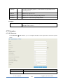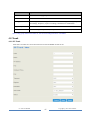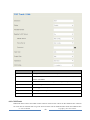
1
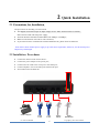
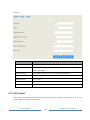
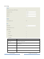
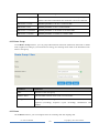
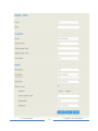
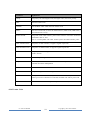
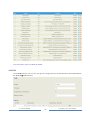
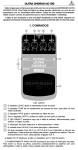
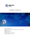
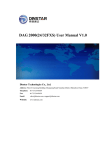
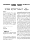
UC100 User Manual v1.0 Dinstar Technologies Co., Ltd. Address: 9th Floor, Guoxing Building, Changxing Road, Nanshan District, Shenzhen, China Postal Code: 518052 Telephone: +86 755 61919966 Fax: +86 755 2645 6659 Emails: [email protected], [email protected] Website: www.dinstar.com, www.dinstar.cn Revision Records Document Name UC100 User Manual v1.0 Document version V1.0 Firmware version 2.53.0.24 Revised by Ivanka Yuan Date 2014.5.19 Table of Contents 1 Product Description.............................................................................................................. 1 1.1 Overview............................................................................................................................... 1 1.2 Application Scenario ............................................................................................................. 1 1.3 Product Appearance ............................................................................................................. 2 1.3.1 Images of UC100............................................................................................................................................................ 2 1.3.2 Description of Ind icators ............................................................................................................................................... 2 1.4 Features & Functions............................................................................................................ 3 1.4.1 Key Features.................................................................................................................................................................... 3 1.4.2 So ftware Features ........................................................................................................................................................... 3 1.4.3 Vo ice Capabilit ies ........................................................................................................................................................... 4 1.4.4 Supplementary Services ................................................................................................................................................ 4 1.4.5 Physical Interfaces.......................................................................................................................................................... 4 1.4.6 FXS ................................................................................................................................................................................... 5 1.4.7 FXO .................................................................................................................................................................................. 5 1.4.8 Mobile .............................................................................................................................................................................. 5 1.4.9 Hardware Specifications & Environ ment................................................................................................................... 5 2 Quick Installation ................................................................................................................. 6 2.1 Precautions for Installation................................................................................................... 6 2.2 Installation Procedures ......................................................................................................... 6 2.3 Network Connection ............................................................................................................. 7 2.3.1 Network Connection Diagram under Route Mode ................................................................................................... 7 2.3.2 Network Connection Diagram under Bridge Mode.................................................................................................. 7 3 Basic Operation .................................................................................................................... 9 3.1 Methods to Number Dialing .................................................................................................. 9 3.2 Call Holding.......................................................................................................................... 9 3.3 Call Waiting .......................................................................................................................... 9 3.4 Call Transfer......................................................................................................................... 9 3.4.1 Blind Transfer.................................................................................................................................................................. 9 3.4.2 Attended Transfer ......................................................................................................................................................... 10 3.4.3 Call Transfer via Pressing Flash-hook...................................................................................................................... 10 3.5 Description of Feature Codes .............................................................................................. 10 3.6 Send or Receive Fax ............................................................................................................ 11 3.6.1 Fax Mode Supported.................................................................................................................................................... 11 3.6.2 Explanation of T.38 and Pass -through ...................................................................................................................... 11 3.7 Restore Default IP and Password ........................................................................................ 12 3.8 Restore Default Setting ....................................................................................................... 12 4 Configurations on Web Inte rface ...................................................................................... 13 4.1 How to Log in Web Interface .............................................................................................. 13 4.1.1 Preparations for Login ................................................................................................................................................. 13 4.1.2 Log in Web Interface.................................................................................................................................................... 13 4.2 Configuration Wizard ......................................................................................................... 14 4.2.1 UC100 regarded as Terminal and Registered to SIP Server .................................................................................. 14 4.2.2 FXS/ FXO Port Registered to SIP Server.................................................................................................................. 15 4.2.3 Other SIP Clients registered to UC100 ..................................................................................................................... 15 4.2.4 UC100 Connected to PBX through Trunking.......................................................................................................... 15 4.3 Status .................................................................................................................................. 16 4.3.1 Overview........................................................................................................................................................................ 16 4.3.2 SIP ................................................................................................................................................................................... 16 4.3.3 PSTN .............................................................................................................................................................................. 17 4.3.4 Current Call ................................................................................................................................................................... 18 4.3.5 CDRs .............................................................................................................................................................................. 19 4.3.6 Service ............................................................................................................................................................................ 19 4.3.7 About .............................................................................................................................................................................. 20 4.4 System ................................................................................................................................ 20 4.4.1 Setting ............................................................................................................................................................................. 21 4.4.2 User Manager ................................................................................................................................................................ 22 4.4.3 Provision ........................................................................................................................................................................ 22 4.4.4 Operation Log ............................................................................................................................................................... 23 4.4.5 Service Log .................................................................................................................................................................... 24 4.4.6 Backup/Restore/Upgrade ............................................................................................................................................ 24 4.4.7 Automatch Impedance ................................................................................................................................................. 25 4.4.8 Vo ice ............................................................................................................................................................................... 25 4.4.9 Reboot ............................................................................................................................................................................ 26 4.5 Network .............................................................................................................................. 26 4.5.1 Setting ............................................................................................................................................................................. 26 4.5.2 Access Control .............................................................................................................................................................. 28 4.5.3 Firewall........................................................................................................................................................................... 29 4.5.4 DHCP Server Setting ................................................................................................................................................... 31 4.5.5 Client List ...................................................................................................................................................................... 31 4.5.6 Po rt Mapping................................................................................................................................................................. 32 4.5.7 DMZ Setting .................................................................................................................................................................. 33 4.5.8 Diagnostics .................................................................................................................................................................... 33 4.6 Profile ................................................................................................................................. 34 4.6.1 SIP Profile ...................................................................................................................................................................... 34 4.6.2 FXS/ FXO ....................................................................................................................................................................... 36 4.6.3 Codec .............................................................................................................................................................................. 39 4.6.4 Nu mber........................................................................................................................................................................... 40 4.6.5 Time ................................................................................................................................................................................ 41 4.6.6 Manipulat ion ................................................................................................................................................................. 41 4.6.7 Dialplan .......................................................................................................................................................................... 42 4.7 Extension ............................................................................................................................ 44 4.7.1 SIP Extension ................................................................................................................................................................ 44 4.7.2 FXS ................................................................................................................................................................................. 45 4.7.3 Ring Group .................................................................................................................................................................... 46 4.8 Trunk .................................................................................................................................. 47 4.8.1 SIP Trunk ....................................................................................................................................................................... 47 4.8.2 FXO Trunk..................................................................................................................................................................... 48 4.8.3 GSM Trunk .................................................................................................................................................................... 49 4.9 Call Control ........................................................................................................................ 50 4.9.1 Setting ............................................................................................................................................................................. 51 4.9.2 Route Group .................................................................................................................................................................. 52 4.9.3 Route............................................................................................................................................................................... 52 4.9.4 Feature Code ................................................................................................................................................................. 54 4.9.5 IVR .................................................................................................................................................................................. 55 4.9.6 SM S ................................................................................................................................................................................ 56 1 Product Description 1.1 Overview UC100 is a multi-functional and all-in-one gateway, which integrates voice service and data service. It provides three voice ports (including GSM, FXS and FXO), offering seamless connectivity to VoIP Network, PLMN and PSTN. Based on SIP, it not only can interacts with VoIP network, but also supports four types of GSM frequency ranges, thus meeting the worldwide requirements about the mobile network. UC100 supports WiFi and has high-speed data-handling capacity, allowing users to enjoy high-speed internet surfing through WiFi or the LAN port. With VPN transparent transfer function, UC100 is ideally suitable for personal use. Meanwhile, it is perfect for small and micro enterprises, providing high-speed internet access, good voice service as well as message service. 1.2 Application Scenario UC100 provides high-quality and cost-effective VoIP solution. Its application scenario is shown as follows: SMS/Call/USSD GSM UC100 FXO SIP LAN PSTN FXS WAN WiFi Trunk Internet Laptop Softphone UC100 User M anual 1 Analog Phone SIP Server Copyright @ 2011-2015 Dinstar 1.3 Product Appearance 1.3.1 Images of UC100 Front View Back View 1.3.2 Description of Indicators Indicator Status Description PWR Flash slowly The system is initialized successfully and is in normal running. On green The system is being initialized. On dull There is no power supply or power supply is abnormal. UC100 User M anual 2 Copyright @ 2011-2015 Dinstar WiFi GSM Flash quickly WiFi is in normal running On dull WiFi is turned off. Flash slowly SIM card has not yet been inserted or SIM card is not registered. FXS/FXO WAN/LAN Flash quickly SIM card is successfully registered. On dull Fault occurs in GSM module Flash slowly FXS/FXO is idle or no off-hook is detected. On green FXS/FXO is in off-hook status. On dull Fault occurs in FXS/FXO module Flash quickly Network is successfully connected. On dull Network does not work or network cable is not connected. 1.4 Features & Functions 1.4.1 Key Features FXS/FXO/GSM interface on a single device/gateway Send/receive calls from PSTN/PLMN via FXO/GSM Flexible dial plan, via time, numbers, source IP etc. IVR customization High speed NAT forwarding, Built-in SIP server, support up to 8 SIP Extensions support WIFI hotspot User-friendly web interface, multiple management ways 1.4.2 Software Features Ring Group Routing Groups Caller/Called Number Manipulation Routing Base on Time Period Routing Base on Caller/Called Prefixes Routing Base on Source Trunks Dial Rules UC100 User M anual 3 Copyright @ 2011-2015 Dinstar Failover Routing FXO Impedance Auto Match IVR Customization Auto Attendant Function CDRs 1.4.3 Voice Capabilities VoIP Protocols: SIP over UDP/TCP/TLS,SDP,RTP/SRTP Codecs: G.711a/μ law,G.723.1, G.729A/B, iLBC,G.726 Silence Suppression Comfort Noise Generator(CNG) Voice Activity Detection(VAD) Echo Cancellation: G.168 with up to 128ms Dynamic Jitter Buffer Adjustable Gain Control Automatic Gain Control (AGC) Call Progress Tones: Dial Tone, Ring Back Tone, Busy Tone FAX: T.38 and Pass-through NAT: STUN/UPnP DTMF: RFC2833/Signal/Inband 1.4.4 Supplementary Services Call Waiting Call Transfer (Blind & Attended) Call Forwarding (Unconditional/Busy/No Reply) Call Holding No Disturbing Hotline 1.4.5 Physical Interfaces FXO Port: 1 FXS Port: 1 SIM Slot: 1 Ethernet Interfaces:1WAN&1LAN 10/100 Base-T RJ45 WIFI:2.4GHz , 802.11n UC100 User M anual 4 Copyright @ 2011-2015 Dinstar 1.4.6 FXS Connector: RJ11 Caller ID: Bellcore Type 1&2, ETSI,BT,NTT and DTMF Answer and Disconnect Signaling: Answer, Disconnect, Busy Tone Polarity Reversal Hook Flash 1.4.7 FXO Connector: RJ11 Caller ID: FSK, DTMF Polarity Reversal Answer Delay Busy Tone Detection No Current Detection 1.4.8 Mobile GSM: 850/900/1800/1900MHz SIM/UIM: 1 SIM/UIM per Channel SIM Card: 1.8V, 3.0V Antenna: 3.0dB, SMA Interface SMS/USSD Bulk SMS SMS Code/Decode: ASCII, Unicode IMEI/PIN Code Management 1.4.9 Hardware Specifications & Environment Power Supply: 12VDC, 1A Power Consumption: 10W Operating Temperature. Storage Temperature: -20 ℃ ~80 ℃ Humidity: 10%-90%, Non-Condensing Dimensions (W/D/H): 126×75×25mm Unit Weight: 0.7kg UC100 User M anual 0 ℃ ~ 45 ℃ 5 Copyright @ 2011-2015 Dinstar 2 Quick Installation 2.1 Precautions for Installation The precautions for installing UC100 include: The adapter of UC100 accepts AC input voltage of 110- 220 V and converts it to 12V DC; Please ensure stable and safe power supply; Network interface should be standard RJ45 with 10Mbps or 100Mbps; Make sure the antenna of UC100 is well-connected; If you want UC100 to communicate with the GSM network, please insert an SIM card. Note: Please check whether power supply is up to the above requirement; otherwise, UC100 and its power adapter may be damaged. 2.2 Installation Procedures Connect the antenna to the UC100 device Connect the power adapter to the power port; Connect network cable to the LAN port or the WAN port; Connect telephone wire to the FXO port and the FXS port; Insert SIM card to the SIM slot. Power Adapter UC100 User M anual WAN Cable LAN Cable 6 Analog Phone Telco Fixed Line Copyright @ 2011-2015 Dinstar 2.3 Network Connection UC100 works in two modes: route mode and bridge mode. When it is under the route mode, the IP address of WAN port must be different from the IP address of LAN port. But when it is under the bridge mode, the IP address of WAN port and the IP address of LAN port are the same. 2.3.1 Network Connection Diagram under Route Mode Under the route mode, the default IP address of WAN port is a DHCP IP address, while the default IP address of the LAN port is a static IP address, namely 192.168.11.1. Note: The IP address of LAN port of UC100 and the IP address of PC are at the same network segment, while the IP address of WAN port is at a different network segment. 2.3.2 Network Connection Diagram under Bridge Mode Under the Bridge mode, both the default IP address of WAN port and that of LAN port are 192.168.11.1. UC100 User M anual 7 Copyright @ 2011-2015 Dinstar Note: The IP address of PC and the IP address of WAN port of UC100 are at the same network segment. For more details about installation, please make reference to Quick Installation Guide. UC100 User M anual 8 Copyright @ 2011-2015 Dinstar 3 Basic Operation 3.1 Methods to Number Dialing There are two methods to dial telephone number or extension number: Dial the called number and wait for 4 seconds for dialing timeout, or dial the called number directly (the system will judge whether the dialing is completed according to the Digitmap dialplan format). Dial the called number and press #. 3.2 Call Holding If a calling party places a call to a called party which is otherwise engaged, and the called party has the call holding feature enabled, the called party is able to switch to the new incoming call while keeping the current call holding on by pressing the flash button or the flash hook. When the called party presses the flash button or the flash hook once again, he or she will switch back to the first call. 3.3 Call Waiting If a calling party places a call to a called party which is otherwise engaged, and the called party has the call waiting feature enabled, the calling party will hear a IVR voice ‘Please hold on, the subscriber you dialed is busy’ and the called party will hear three beeps. By pressing the flash button or the flash hook, the calling party is able to switch between the new incoming call and the current call. 3.4 Call Transfer When a calling party is in conversation with the called party, call transfer allows one of them to shift the call connection to a third party. 3.4.1 Blind Transfer Blind transfer is a call transfer in which the transferring party connects the call to a destination extension before ringback begins (the transferring party will not hear any ringback). Example: A and B are in conversation and B wants to transfer the conversation to C (the extension of C is 8000). Operation instructions are as follows: UC100 User M anual 9 Copyright @ 2011-2015 Dinstar 1. B dials *18000 (*1 is the feature code for blind transfer, 8000 is the extension of C); 2. B hangs up the call; 3. After C picks up the phone, A and C go into conversation. 3.4.2 Attended Transfer Attended transfer is one in which the transferring party either connects the call to a ringing phone (ringback heard) or speaks with the third party before connecting the call to the third party. Example: A and B are in conversation and B wants to consultatively transfer the conversation to C (the extension of C is 8000). Operation instructions are as follows: 1. B dials *28000 (*2 is the feature code for attended transfer, 8000 is the extension of C); 2. The extension of C rings; 3. If C answers the call, C and B go into conversation; 4. If C hangs up the phone, B and A continue to be in conversation; 5. If B hangs up the phone and C picks up the phone, C and A go into conversation. 3.4.3 Call Transfer via Pressing Flash-hook Example: A and B are in conversation and B wants to transfer the call to C via pressing the flash-hook (the extension of C is 8000). Operation instructions are as follows: 1. B presses the flash-hook and dials 8000; 2. The extension of C rings; 3. If C answers the call, B and C go into the conversation while the conversation between B and A is still held on. 4. If B presses the flash-hook again and dials 1, conversation is switched back between B and A; 5. If B presses the flash-hook again and dials 2, conversation is switched between B and C. 3.5 Description of Feature Codes Code Corresponding Function *158 Dial *158 to inquiry LAN IP *159 Dial *159 to inquiry WAN IP *114 Dial *114 to inquiry phone number *157* Dial *157*0 to set route mode; dial *157*1 to set bride mode *150* Dial *150*1 to set IP address as static IP address; dial *150*2 to set IP address as DHCP IP address *152* Dial *152*192*168*1*10# to set IPv4 address as 192.168.1.10 UC100 User M anual 10 Copyright @ 2011-2015 Dinstar *156* Dial *152*192*168*1*1# to set IPv4 gateway as 192.168.1.1 *153* Dial *153*255*255*0*0*# to set IPv4 netmask as 255.255.0.0 *111 Dial *111 to restart the UC100 device *51 Dial *51 to enable the call waiting service *50 Dial *50 to disable the call waiting service *1 Example: Dial *18000, and you can blind transfer to the extension number 8000 *2 Example: Dial *28000#, and you can attended transfer to the extension number 8000 *72* Enable unconditional call forwarding service. Example: Dial *72*8000, and calls will be unconditionally forwarded to extension number 8000 *73 Disable unconditional call forwarding service *90* Enable the call forwarding on busy service. Example: Dial *90*8000, and calls will be forwarded to extension number 8000 when the called number is on busy *91 Disable the call forwarding on busy service *92* Enable the call forwarding on no reply service. Example: Dial *92*8000, and calls will be forwarded to extension number 8000 when there is no reply from the called number *93 Disable the call forwarding on no reply service *78 Enable the ‘No Disturbing’ service *79 Disable the ‘No Disturbing’ service ** Pick up the ringing extension which is in the same ringgroup. Example: Dial**8000, and you can take the incoming call of extension number 8000 Note: A voice prompt indicating successful configuration will be given after each configuration procedure. Please do not hang up until listening to this voice prompt. 3.6 Send or Receive Fax 3.6.1 Fax Mode Supported T.38(IP-based) T.30(Pass-through) 3.6.2 Explanation of T.38 and Pass-through T.38: T.38 is used to transfer faxes over IP networks in real time. It could convert the analog fax signal into digital fax signal and could transform it back from T.38 into analog signal. Fax data are transmitted. Under the T.38 mode, fax traffic is carried in T.38 packages. UC100 User M anual 11 Copyright @ 2011-2015 Dinstar Pass-through: Under the pass-through mode, fax signal is not converted and fax traffic is carried in RTP packets. It uses the G.711 A or G711U codec in order to reduce the damage to fax signal. 3.7 Restore Default IP and Password Press the RST button of UC100 for 3 seconds to 6 seconds, the IP address, username and password of the device will be restored to factory defaults. Press the RST button of UC100 for more than 6 seconds, and all configurations of the device will be restored to the default settings. 3.8 Restore Default Setting If you want to restore UC100 to default settings, you can press the RST button of UC100 for more than 6 seconds or you can configure it on the Web interface. Click System Backup/Restore/Upgrade on the Web of UC100, and select the parts (system, network or network) that need to be restored to defaults, click Reset, restart the UC100 device, and the selected parts will be restored to defaults. UC100 User M anual 12 Copyright @ 2011-2015 Dinstar 4 Configurations on Web Interface 4.1 How to Log in Web Interface Connect UC100 to the network according to the following network topology, and dial *158 to query the IP address of the UC100 device. Internet Router UC100 Switch PC 4.1.1 Preparations for Login Modify the IP address of the PC to make it at the same network segment with the UC100 device, since the default IP address of the UC100 device is 192.168.11.1. Check the connectivity between the PC and the UC100. Click Start Run of PC and enter cmd to execute ‘ping 192.168.11.1’ to check whether the IP address of the UC100 runs normally. 4.1.2 Log in Web Interface Open a web browser and enter the IP address of the UC100 (the default IP is 192.168.11.1). Then the login GUI will be displayed. Both the default username and password are admin. It is suggested that you should modify the username and password for security consideration. UC100 User M anual 13 Copyright @ 2011-2015 Dinstar Then the following interface will be displayed. Index Item Description 1 UC100 The name of the gateway; it can be edited on the System Setting interface 2 Menu Bar The menu bar of UC100 3 Unsaved Changes All configurations or modifications should be saved. Click the button, and you can see a log of all changes. Changes won’t take effect until they are saved. 4 Auto Refresh Button The button can be enabled or disabled. If it is enabled, the information on the Status Overview/SIP/PSTN/Current Call interfaces will be refreshed automatically 3 Detailed interface The detailed configuration interface or display interface 4.2 Configuration Wizard The following are the common ways to configure the UC100 device. 4.2.1 UC100 regarded as Terminal and Registered to SIP Server Add an SIP Trunk to SIP Server Enable Register for the SIP Trunk Add Inbound and Outbound Routes UC100 User M anual 14 Copyright @ 2011-2015 Dinstar 4.2.2 FXS/FXO Port Registered to SIP Server Add an SIP Trunk to SIP Server Enable Register for FXS/FXO Port and Adopts the SIP Trunk Note: If Register is enabled for FXS/FXO port, calls through FXS/FXO port will take inbound and outbound routes as first priority. For outgoing calls, if outbound route cannot be matched, then the registered SIP trunk will be selected. For incoming calls, if inbound route cannot be matched, then the registered FXS/FXO port will be selected. 4.2.3 Other SIP Clients registered to UC100 Under this mode, UC100 is regarded as an SIP Server. Create an extension account first on the Extension SIP interface of UC100, and configure listening port on the Profile SIP interface. Then, configure the UC IP address, extension account and listening port on SIP Clients. Add Extension Account on Extension SIP Interface Configure Information on SIP Client 4.2.4 UC100 Connected to PBX through Trunking Add an SIP Trunk to PBX Add Inbound and Outbound Routes UC100 User M anual 15 Copyright @ 2011-2015 Dinstar 4.3 Status 4.3.1 Overview Log in the Web interface of UC100, click Status Overview, and the following interface will be displayed. On the interface, information about the system, performance, WAN network, LAN network, WiFi and DHCP server is shown. 4.3.2 SIP Click Status SIP, and the following interface will be displayed. On the interface, information of SIP profile, SIP Trunk and SIP extension is shown. UC100 User M anual 16 Copyright @ 2011-2015 Dinstar Belong To Profile Parameter Explanation Listening Address The current listening address and port of SIP State Green color means normal running, while red color means listening address and port of SIP is unavailable. There are two states :Running and Down SIP Trunk Heartbeat If heartbeat is enabled, option message will be sent to peer device (the peer device is reachable) Status Green color means available, while red color means abnormal, unavailable or prohibited. There are five statuses: Running, Reged/Up, Noreg/Up, Trying-Down, Fail-Wait SIP Extension Profile The profile that is used by the SIP trunk Profile The profile that is used by the SIP extension Status SIP extension is registered or not. There are two statuses: Registered. Unregistered 4.3.3 PSTN Click Status PSTN, and the following interface will be displayed. On the interface, information of FXS port, FXO port and GSM port is shown. Green color means available or registered, while red color means abnormal, unregistered or prohibited. UC100 User M anual 17 Copyright @ 2011-2015 Dinstar Belong to Parameter Include FXS State Ready, Unready Config Status OK, Config Failed SIP Register Status Registered, Unregistered State Ready, Unready Config Status OK, Config Failed SIP Register Status Registered, Unregistered Hook State Onhook, Offhook Line State Online, Offline State Ready, Unready Channel State OK, Config Failed SIP Register Status Registered, Unregistered FXO GSM Signal : No SIM card has been inserted : Signal Strength 4.3.4 Current Call Click Status Current Call, and the following interface will be displayed. On the interface, the source, destination, calling number, called number, start time, answer time, state and duration of the current realtime call are shown. If there is no current call, no information will be shown. UC100 User M anual 18 Copyright @ 2011-2015 Dinstar Parameter Explanation Src The source of the current call Dest The destination of the current call State There are three states: Active: it means the caller and the called party is on conversation Ringing: it means the phone of the called party is ringing Early: It means the ring-back tone of the current call is manipulated 4.3.5 CDRs Click Status CDRs, and you can set query criteria to query the CDRs that you want on the displayed interface. Meanwhile, you are allowed to clear CDRs or export CDRs through pressing the Empty or Export button. The maximum number of CDRs that can be saved is 1000. Hangup causes include normal clearing, no answer, caller cancel, user busy, circuit congestion, exchange routing error, recovery on timer expire, and none. 4.3.6 Service Click Status Service, and the service status of UC100 is displayed. The function is enabled by default. The Web, SSH and Telnet service can be disabled and their ports can be modified on the System Access Control interface. If no running status is shown, it means exception has occurred on UC100. Besides, if syslog is disabled on the System Setting interface, the logs cannot be uploaded to the server, but log service is still running. UC100 User M anual 19 Copyright @ 2011-2015 Dinstar 4.3.7 About Click Status About, copyright, device model, hardware version and firmware version are displayed. 4.4 System Configurations for language, time zone, NTP, login password, access control, provision, operation log, service log, upgrade, backup, restore, automatch impedance, IVR upload and device reboot can be carried out in the System section. UC100 User M anual 20 Copyright @ 2011-2015 Dinstar 4.4.1 Setting Parameter Explanation Host Name The name of the gateway. After it is configured, the name will be displayed on the left of the menu bar. Language Auto: the language of UC100 will be automatically adjusted into the language of the web browser. Auto is the default value. English: the language of UC100 is English. Chinese: the language of UC100 is Chinese. Time Zone You can choose a time zone you want. The default value is UTC (Universal Time Coordinated) UC100 User M anual 21 Copyright @ 2011-2015 Dinstar Local Time The current time based on current time zone. It is synchronized with NTP. CDRs If it is enabled, CDRs will be saved automatically. 1000 CDRs call be saved at most and they can be queried on the Status CDRs interface. If it is disabled, CDRs will not be saved. Service Log Level There are eight levels, including Debug, Info, Notify, Warning, Error, Critical, Alert and Emergency. Time If NTP server is enabled, the UC100 can be synchronized with the world standard Synchronization time. Meanwhile, you’re able to add or reduce NTP servers. Please consult local telecom operators or surf the internet for the address of NTP servers. Delete a NTP Server Add a NTP Server 4.4.2 User Manager Click System User Manager, and you can modify the username name and password for logging in the UC100 device. Factory defaults for username name and password are both admin, so it is advised that you should modify them for security consideration. The abovementioned username and password are also used to log in Web Interface, Telnet and SSH. 4.4.3 Provision Provision is used to make UC100 automatically upgrade with the latest firmware stored on an http server an ftp server or a tftp server. Select the checkbox on the right of Enable, and you will see the following interface: UC100 User M anual 22 Copyright @ 2011-2015 Dinstar Parameter Explanation URL The URL of the http/ftp/tftp server for example: ftp://172.16.77.200/home tftp://172.16.77.200/provision.xml http://test.domain.com/test username The login username of the http/ftp/tftp server Password The login password of the http/ftp/tftp server Note: Proxy Address, Proxy Username and Proxy Password are optional to be configured. 4.4.4 Operation Log The logs tracing the operations carried out on the Web can be queried on the System Operation Log interface. You are allowed to set query criteria to query the logs that you want and to export the logs through clicking the Export button at the top-right corner. UC100 User M anual 23 Copyright @ 2011-2015 Dinstar 4.4.5 Service Log Service logs (the running logs of UC100) can be exported on the System Service Log interface. Those logs are used for analyzing where a problem has occurred on UC100. 4.4.6 Backup/Restore/Upgrade On the System Backup/Restore/Upgrade interface, you can back up or restore configuration data, and can upgrade UC100 to a new version. But you need to restart the device for the change to take effect after executing restore or upgrade. Parameter Explanation Reset Click Reset, and all configuration will be restored to factory defaults. Restore Choose a backup file, and then click Restore. Upgrade Choose an upgrade file (which is provided by Shenzhen Dinstar Technologies), and then click Upgrade. UC100 User M anual 24 Copyright @ 2011-2015 Dinstar 4.4.7 Automatch Impedance Automatch impedance is used to improve the interoperability of the FXO port with other devices. How to use automatch impedance: 1. Connect a telephone cable to the FXO port; 2. Click Detection, and the UC100 device will automatically detect the optimum impedance (It takes a period of time to carry out the detection). 3. Save the optimum impedance. Note: You can enter any digits for DTMF number; the default DTMF number 1234567890123456789. 4.4.8 Voice On the System Voice interface, you can upload an English IVR file or a Chinese IVR file according to your needs. At present, only those IVR files in wav format are allowed. Note: An IVR file has yet to be uploaded in the above figure; The format of the wav audio file must be: monaural, 8000hz, 16bit, play time of less than 30s, and size of no more than 1M bytes; UC100 User M anual 25 Copyright @ 2011-2015 Dinstar If the following yellow bars appear, it means the UC100 device lacks an IVR file and you need to upload one. 4.4.9 Reboot On the System Reboot interface, you can click Perform Reboot to reboot the UC100 device. After the device is rebooted, those configurations that have been saved will remain unchanged. 4.5 Network UC100 works in two modes: route mode and bridge mode. When it is under the route mode, the IP of WAN must be different from the IP of LAN. But when it is under the bridge mode, the IP of WAN and the IP of LAN are the same. 4.5.1 Setting Under the route mode, the default IP address of WAN port is a DHCP IP address, while the default IP address of the LAN port is 192.168.11.1. In fact, there are three kinds of IP addresses for selection for the WAN port, including Static IP address, DHCP IP address and PPPOE IP address. DHCP: Obtain IP address automatically. UC100 is regarded as a DHCP client, which sends a broadcast request and looks for a DHCP server to answer. Then the DHCP server automatically assigns an IP address to the UC100 from a defined range of numbers configured for a given network. UC100 User M anual 26 Copyright @ 2011-2015 Dinstar Static IP Address: Static IP address is a semi-permanent IP address and remains associated with a single computer over an extended period of time. This differs from a dynamic IP address, which is assigned ad hoc at the start of each session, normally changing from one session to the next. If you choose static IP address, you need to fill in the following information: IP Address: the IP address of the WAN port of the UC100 ; Netmask: the netmask of the router connected the UC100; Default Gateway: the IP address of the router connected the UC100; Use custom DNS server: the IP address of the DNS server UC100 User M anual 27 Copyright @ 2011-2015 Dinstar PPPoE: PPPoE is an acronym for point-to-point protocol over Ethernet, which relies on two widely accepted standards: PPP and Ethernet. PPPoE is a specification for connecting the users on an Ethernet to the Internet through a common broadband medium, such as a single DSL line, wireless device or cable modem. PPPOE IP address refers to IP address assigned through the PPPoE mode. If you choose PPPoE, you need to fill in to fill in the following information: Username: the account name of PPPoE Password: the password of PPPoE Server Name: the name of the server where PPPoE is placed Note: The default IP address of WAN port is a DHCP IP address, but in actual conditions, the IP address of WAN port is more often set as a static IP address. 4.5.2 Access Control The access ports of Web, Telnet and SSH, as well as relevant on-off controls, can be configured on the Access Control interface. Web supports http and https, while SSH supports OAuth 2.0 protocol. UC100 User M anual 28 Copyright @ 2011-2015 Dinstar 4.5.3 Firewall If the UC100 works under the route mode, you can choose to enable the firewall and set filter rules to accept or reject certain destination IP addresses. Configuration Procedures: 1. Select On in the drop-down box on the right of Filter Rules Control 2. Select filter action, accept or reject; 3. Click the New button. UC100 User M anual 29 Copyright @ 2011-2015 Dinstar Note: : Edit information for the corresponding filter rule. : Delete the corresponding filter rule. /*: Information of Source or Destination is not completely filled in. 4. Fill in relevant information in the following interface. Parameter Explanation LAN IP The IP address of LAN port that you want UC100 to accept or reject LAN Port The LAN port which the accepted or rejected IP address belongs to LAN Mac The Mac of the LAN port that is accepted or rejected WAN IP The IP address of WAN port that you want UC100 to accept or reject WAN Port The WAN port which the accepted or rejected IP address belongs to Action Choose accept or reject 5. Click the Save button. UC100 User M anual 30 Copyright @ 2011-2015 Dinstar 4.5.4 DHCP Server Setting If there is a need, you can choose to enable the built-in DHCP server of UC100 to assign IP addresses to PC or other clients that are in the same local-area network with UC100. Parameter Explanation Start Address The start IP address to be assigned End Address The end IP address to be assigned Lease Time Period of validity Gateway The IP address of UC100; it is optional to fill in Master DNS The master DNS of the client whose IP address is assigned by the built-in DHCP server of UC100; it is optional to fill in Slave DNS The master DNS of the client whose IP address is assigned by the built-in DHCP server of UC100; it is optional to fill in 4.5.5 Client List On the Network Client List interface, information of the client devices whose IP addresses are assigned by the built-in DHCP server of UC100 is displayed. UC100 User M anual 31 Copyright @ 2011-2015 Dinstar 4.5.6 Port Mapping IF the UC100 works under the route mode, port mapping allows a client in the wide-area network to visit a client in the local-area network. Configuration Procedures: 1. Click Network Port Mapping, and the following interface will be shown. 2. Click the New button. 3. Fill in information on the following interface. Parameter Explanation Name The name of the port mapping UC100 User M anual 32 Copyright @ 2011-2015 Dinstar WAN Port The WAN port of the client in the wide-area network Protocol Choose TCP, UDP or TCP/UDP LAN IP The IP address of the LAN port of the to-be-visited client in local-area network LAN Port The LAN port of the to-be-visited client in local-area network 4. Click the Save button. 4.5.7 DMZ Setting If the UC100 works under the route mode and the DMZ service is enabled, the clients in the wide-area network are allowed to have direct access to the clients in the DMZ (demilitarized zone). 4.5.8 Diagnostics There are three utilities to diagnose the network, including Ping, Traceroute and Nslookup. Ping is used to examine whether a network works normally through sending test packets and calculating response time. Instructions for using Ping: 1. Enter the IP address or domain name of a network, a website or a device in the input box of Ping, and then click Ping. 2. If related messages are received, it means the network works normally; otherwise, the network is not connected or is connected faultily. Traceroute is used to determine a route from one IP address to another. Instruction for using Traceroute: 1. Enter the IP address or domain name of a destination device in the input box of Traceroute, and then click Traceroute. 2. View the route information from the returned message. Nslookup (Name Server Lookup) is a network command-line tool to obtain domain name of internet or to UC100 User M anual 33 Copyright @ 2011-2015 Dinstar diagnose the problems of DNS. Instruction for using Nslookup: 1. Enter a domain name and then click Nslookup. 2. View the DNS information from the returned message. Network Capture On the following interface, you can capture data packages of the available network ports. You can also set source IP, source port, destination IP or destination port to capture the packages that you want. 4.6 Profile 4.6.1 SIP Profile On the Profile SIP interface, you can set SIP information such as listening port, which will be used in FXO/FXS, extension and SIP trunk. Multiple SIP profiles can be configured for one UC100 device, so you can choose different SIP profiles according to different needs. UC100 User M anual 34 Copyright @ 2011-2015 Dinstar Parameter Explanation Name The name of the SIP profile Local Listening Port The local listening port of SIP. If the SIP profile is used by a SIP trunk, the port filled in here is the listening port for the SIP trunk. NAT Methods for NAT traversal, including uPNP/NAT-PMP, IP Address, Stun, and Host. DTMF There are three modes, including SIP Info, INBAND, RFC2833. RFC2833-PT RFC2833 payload coding PRACK Provisional Response ACKnowledgement Session Timeout The validity period of current registration. It is 1800 seconds by default Inbound Codec UC100 User M anual To take the remote device or the local device as priority for inbound codec 35 Copyright @ 2011-2015 Dinstar Negotiation Priority negotiation. Assume local device supports PCMA, PCMU, G.729 and G.723, while the remote device supports G.723 and G.729. If remote device is taken as codec negotiation priority, G.723 will be the codec mode, since the remote device supports G.723 and G.729 and G.723 is prior to G.729. 4.6.2 FXS/FXO On the Profile FXS/FXO interface, you can configure the driving parameters of FXS port and the FXO port. Profile FXS Interface: UC100 User M anual 36 Copyright @ 2011-2015 Dinstar Parameter Explanation Name The name of the FXS profile Tone Group The state standard of dialing tone, busyness tone and ring tone; the default value is China Digit Timeout (s) The timeout value for dialing a digit of a telephone number Dial Timeout (s) The timeout value for dialing the first telephone number after off-hook Ring Timeout (s) The timeout value for the ringing of the analog phones of the FXS port when there are incoming calls No Answer Timeout (s) The timeout value for ending calls which go out through FXS port Flash Detection Whether to execute flash detection; If flash detection is not executed, the press on flash-hook won’t be processed. DTMF Send Interval(ms) The minimum interval between the sending of two DTMF tone DTMF: Dual Tone Multi Frequency DTMF Gain Signal gain of DTMF DTMF Duration (ms) The minimum duration of a DTMF tone CID Send Mode Include FSK and DTMF; generally it is the default setting FSK: Frequency-shift keying CID: Caller ID Message Mode Include SDM F and M DM F; generally it is the default setting Message Format Include Display Name and CID, Only display Name, Only display CID Send CID Before Ring If it is enabled, the CID will be shown before ring; otherwise, CID will be displayed after ringing Send CID After Ring(ms) The interval between ringing and displaying of CID Impedance The impedance matched with analog phones; Generally it is the default setting Polarity Reverse If polarity reverse is on, call tolls will be calculated based on the changes in voltage. If polarity reverse is off, you need to set the time to delay offhook and call tolls will be calculated starting from the preset time. Dialplan UC100 User M anual The rules for dialing 37 Copyright @ 2011-2015 Dinstar Profile FXS Interface: Parameter Explanation Name The name of the FXO profile Tone Group The state standard of dialing tone, busyness tone and ring tone; the default value is China Digit Timeout (s) UC100 User M anual The timeout value for dialing a digit of a telephone number 38 Copyright @ 2011-2015 Dinstar Dial Timeout (s) The timeout value for dialing the first telephone number after off-hook Ring Timeout (s) The timeout value for the ringing of the phones of the FXO port when there are incoming calls No Answer Timeout (s) The timeout value for ending calls which go out through FXO port Polarity Reverse If polarity reverse is on, call tolls will be calculated based on the changes in voltage. If polarity reverse is off, you need to set the time to delay offhook and call tolls will be calculated starting from the preset time. DTMF Send Interval(ms) The minimum interval between the sending of two DTMF tone DTMF: Dual Tone Multi Frequency DTMF Gain Signal gain of DTMF DTMF Duration (ms) The minimum duration of a DTMF tone Detect Caller ID Whether to detect caller ID; default value is ‘On’ Ring Detection Detect caller ID after ringing or detect caller ID before ringing Dialplan The rules for dialing 4.6.3 Codec UC100 supports four codec modes, including G711A, G711u, G729 and G92. You can adjust the priority of these four modes according to you needs. UC100 User M anual 39 Copyright @ 2011-2015 Dinstar : Edit codec profile. : Delete the corresponding codec profile or a codec mode. 4.6.4 Number On the Profile Number interface, you can set a prefix for calling numbers or called numbers. When the prefix of a calling number or a called number matches the set prefix, the call will be passed to choose a route. Click the New button, and you will see the following interface: Parameter Explanation Name The name of the number profile Prefix of Caller Number The prefix of the calling number. It supports regular expression. Prefix Number The prefix of the called number. It supports regular expression. of Called Length The length of the calling number or called number. For example, :4|6|7 means the calling number or called number must be 4 digits, 6 digits or 7 digits except the prefix. UC100 User M anual 40 Copyright @ 2011-2015 Dinstar 4.6.5 Time On the Profile Time interface, you can set a time period for calls. When the calling time of a call falls into the set time period, the call will be passed to choose a route. Click the New button, and you will see the following interface: Parameter Explanation Date Period Choose a start date and an end date Weekday Choose a weekday Time Period Choose start and end time 4.6.6 Manipulation Number manipulation refers to the change of a called number or a caller number during calling process when the called number or the caller number matches the preset rules. UC100 User M anual 41 Copyright @ 2011-2015 Dinstar Parameter Explanation Delete Prefix The number of digits that are deleted from the left of the caller number or calling number Delete Suffix The number of digits that are deleted from the right of the caller number or calling number Add Prefix The prefix added to the caller number or the calling number Add Suffix The suffix added to the caller number or the calling number Replace by The number which replace the caller number or the calling number If the checkbox on the right of Caller is selected, it means the caller number will be manipulated; if the checkbox on the right of Called is selected, it means the called number will be manipulated. Note: During number manipulation, deletion rules are carried out first, followed by adding rules. If ‘Replace by’ has been set, deletion rules and adding rules are invalid. 4.6.7 Dialplan Dialplan is used for the dialing of calls through FXS and FXO ports. Regex (Regular Expression) Syntax UC100 User M anual 42 Copyright @ 2011-2015 Dinstar Explanation of frequently-used metacharacters in Regex: ^ Matches the starting position in a string. For example, ^134. $ Matches the ending position of a string. For example, 2$. | Separates alternate possibilities. For example 2|3|4. / Quote the next metacharacter. [] Matches a single character that is contained within the bracket. For example, [123] matches 1, 2, or 3. [0-9] specifies a range which matches any lowercase letter from "0" to "9". [^ ] Matches any one character except those enclosed in [ ]. For example, [^9]. . Matches a single character of any value, except end of line. ? Indicates there is zero or one of the preceding element. For example, colou?r matches both color and colour. * Indicates there is zero or more of the preceding element. For example, ab*c matches ac, abc, abbc, abbbc, and so on. + Indicates there is one or more of the preceding element. For example, ab+c matches abc, abbc, abbbc, and so on, but not ac. Examples: ^0755 Matches the phone numbers with starting digits of 0755. ^0755|^8899|^0110 Matches the phone numbers with starting digits of 0755, 8899 or 0110. ^[1][358][0-9]{9}$ Matches the phone numbers with the first digit as 1, the second digit as 3, 5 or 8, the left nine digits as any of 0 to 9. Digit Map Syntax Supported Digit 0-9 objects T Timer DTMF A digit, a timer, or one of the symbols of A, B, C, D, #, or *. [] One or more DTMF symbols enclosed in the [], but only one DTMF symbol Range can be selected. Range () Separator One or more expressions enclosed the (), but only one can be selected. | Separated expressions or DTMF symbols. UC100 User M anual 43 Copyright @ 2011-2015 Dinstar Subrange - Two digits separated by hyphen (-) which matches any digit between and including the two. Wildcard x Matches any digit of 0 to 9 Modifiers . Matches 0 or more times of the preceding element Modifiers ? Matches 0 or 1 times of the preceding element Examples: (13 | 15 | 18)xxxxxxxxx Matches the phone numbers with stating digits as 13, 15 or 18 and the left nine digits as any of 0 to 9. 4.7 Extension 4.7.1 SIP Extension On the Extension SIP interface, you can configure the SIP accounts registered in the UC100 by SIP clients. Parameter Explanation Name The name of the SIP extension UC100 User M anual 44 Copyright @ 2011-2015 Dinstar Extension The registered SIP account Password The password of the extension DID Direct Inward Dialing; if the called number is same with DID, the call will be directly forwarded to the extension, rather than choosing a route. Register Source If ‘Any’ is chosen, all SIP clients are allowed to register the SIP account of this extension; if ‘Specified’ is chosen, only the SIP client with the specified IP address is allowed to register the SIP account of this extension. SIP Profile Make reference to Profile SIP Status If it is enabled, the SIP account can be registered; Otherwise the SIP account cannot be registered. 4.7.2 FXS On the Extension FXS interface, you can configure data for extensions of the FXS port. UC100 User M anual 45 Copyright @ 2011-2015 Dinstar Parameter Explanation Extension The extension number of FXS port Status If it is enabled, the FXS port is available; if it is disable, the FXS port is unavailable DID Direct Inward Dialing; if the called number is same with DID, the call will be directly forwarded to the extension, rather than choosing a route. Register to SIP Server If it is enabled, the FXS extension account will be registered to the SIP trunk that has been set. Master Server The address and port of the master SIP server; make reference to Trunk SIP Slave Server The address and port of the slave SIP server; make reference to Trunk SIP The slave server will be in use when it is successfully registered but the master server fails to be registered. Input Gain The receiving gain of the FXS port Output Gain The sending gain of the FXS port FXS Profile Make reference to Profile FXS/FXO 4.7.3 Ring Group On the Ring Group interface, you can group FXS extension and SIP extension(s) together and set strategy for choosing the FXS extension and which SIP extension to ring under a ring group. The ring group function is widely used in call centers. UC100 User M anual 46 Copyright @ 2011-2015 Dinstar Parameter Explanation Name The name of the ring group Members Select Select the FXS extension and an SIP extension or several SIP extensions ; Strategy The strategies for choosing which SIP extension to ring, including Sequence (Ascending), Sequence (Cyclic Ascending), Simultaneous and Random Ring Group Number The called number DID Same with Ring Group Number; it is optional to fill in. Note: If ring group function has been set, the call forwarding function is unavailable. 4.8 Trunk 4.8.1 SIP Trunk SIP trunk can realize the connection between UC100 and IPPBX or SIP servers. UC100 User M anual 47 Copyright @ 2011-2015 Dinstar Parameter Explanation Name The name of the SIP trunk IP Address The IP address or domain name of the peer devices or servers Port The SIP listening port of the peer devices or servers; 5060 is the default port Outbound Proxy If outbound proxy is used, enter the IP address or domain name of the proxy server Port If outbound proxy is used, enter the listening port of the proxy server Transport Transport protocol: TCP or UDP Register Whether the SIP trunk is registered or not Heartbeat If heartbeat in on, heartbeat messages (options) will be sent to examine the connection with servers. The default value is ‘Off’. SIP Profile The SIP profile of the SIP Trunk; make reference to Profile SIP Status If it is enabled, it means the SIP Trunk is available; otherwise, the SIP trunk is unavailable. Note: If UC100 is regarded as a terminal and registered to SIP server, and you want to register the UC100, you just need to register the corresponding SIP trunk. 4.8.2 FXO Trunk FXO Trunk interconnects the PSTN with UC100. Calls from the PSTN can come into UC100 and calls can go out from UC100 to search telephone numbers under the PSTN. Different from the FXO ports of other gateways, the FXO port of UC100 only allows one-time dialing, which means called numbers needs to be dialed directly for calls that go out from the FXO port. UC100 User M anual 48 Copyright @ 2011-2015 Dinstar Parameter Explanation Extension The registered SIP account of the FXO port Status If it is enabled, it means the FXO trunk is available; otherwise, the FXO trunk is unavailable Autodial Number The autodial number for incoming calls through FXO port Register to SIP Server Whether to register the FXO trunk to SIP server Input Gain Receiving gain of FXO port Output Gain Sending gain of FXO port FXO Profile Make reference to Profile FXS/FXO 4.8.3 GSM Trunk GSM trunk interconnects the GSM wireless network with UC100. Calls from the GSM wireless network can come into UC100 and calls can go out from UC100 to search mobile numbers under the GSM wireless UC100 User M anual 49 Copyright @ 2011-2015 Dinstar network. Parameter Explanation Extension The registered SIP account of the GSM port Status If it is enabled, it means the GSM trunk is available; otherwise, the GSM trunk is unavailable Autodial Number The autodial number for incoming calls through GSM port Register to SIP Server Whether to register the GSM trunk to SIP server SMS Encoding uc s2 or 7bit SMS Center Number The SMS center number of SIM card provider Pin Code The Pin code of SIM card 4.9 Call Control This section is to configure the routes and trunks for incoming and outgoing calls through UC100, as well as IVR, SMS, fax and call-related security. UC100 User M anual 50 Copyright @ 2011-2015 Dinstar 4.9.1 Setting Parameter Explanation Disconnect call when no RTP packet If it is enabled, and no RTP packets are received within the preset time, calls will be disconnected Language of Tone English or Chinese; you can upload customized IVR on the System Voice interface. RTP Start Port The start port of RTP packets RTP End Port The end port of RTP packets Local extension call If it is enabled, calls between local extensions do not need routes. UC100 User M anual 51 Copyright @ 2011-2015 Dinstar Fax Mode T38 or T30(Pass-through) Tone Detection by Local If it is enabled, UC100 will detect fax tones automatically during a call and the call will be switched into fax mode after a fax tone is detected. SDP Param ‘a=X-fax’ Attribute parameter ‘a=X-fax’ is carried in SDP SDP Param ‘a=fax’ Attribute parameter ‘a=fax’ is carried in SDP SDP Param ‘a=X-modem’ Attribute parameter ‘a=X-modem’ is carried in SDP SDP Param ‘a=modem’ Attribute parameter ‘a=modem’ is carried in SDP 4.9.2 Route Group On the Route Group interface, you can group FXS extension and trunks (SIP trunk, FXO trunk or GSM trunk) together according to your needs and set strategy for choosing which trunk as the destination route under a route group. Parameter Explanation Name The name of the route group Members Select Select the FXS extension and a trunk or several trunks Strategy The strategies for choosing which trunk as the destination route, including Sequence (Ascending), Sequence (Cyclic Ascending), Simultaneous and Random 4.9.3 Route On the Route interface, you can configure routes for incoming calls and outgoing calls. UC100 User M anual 52 Copyright @ 2011-2015 Dinstar UC100 User M anual 53 Copyright @ 2011-2015 Dinstar Parameter Explanation Priority The priority for choosing the route; the higher value, the lower priority Name The name of the route Condition The condition under which the route will be used Source The source of the call; it can be the FXS extension, FXO trunk ,GSM trunk, a customized source or any Number Profile The profile of the caller number; please make reference to Profile Number The default value is ‘Off’ Note: it is incompatible with caller number prefix and called number prefix Caller Number Prefix The prefix of caller number; it supports regular expression Called Number Prefix The prefix of called number; it supports regular expression Time Profile The profile of time during which the route can be used; make reference to Profile Time Action Include manipulating number and send call to destination Manipulation If it is on, the caller number of the route will be manipulated; make reference to Profile Number Manipulation Destination The destination of the route Failover Action The processing when a call through this route fails Condition If busy or timeout is selected, only the failed calls due to busyness or timeout will be processed. If both are not selected, all failed calls will be processed Other Condition Code The code of other conditions; please separate codes with ‘,’ 4.9.4 Feature Code UC100 User M anual 54 Copyright @ 2011-2015 Dinstar Note: All feature codes are enabled by default. 4.9.5 IVR On the IVR interface, you can carry out specific configurations for the IVR which has been uploaded from the System Voice interface. UC100 User M anual 55 Copyright @ 2011-2015 Dinstar Parameter Explanation Status If it is disabled, the VCR cannot be seen in the destination of route. Timeout If it is set as ‘10’, it means if no DTMF tone is received during 10 seconds, the IVR will be played repeatedly or the call will be hanged up. The default value is 20 seconds. Enable Direct Extension Whether to allow direct dialing of extensions during the playing of IVR Repeat Loops If it is set as ‘3’, the call will be hanged up after the IVR has been repeated for three times during timeout. Menu It is the menu of quick-dial numbers for extensions or trunks. If it is a quick-dial for trunks, you need to configure the called number. Quick-dial numbers are 0 to 9. 4.9.6 SMS If an SIM card has been inserted into the GSM port, you can send or receive SMS on the SMS interface. Send Message Enter contents into the box on the left, and then input the number of recipient . Click Send in the last. Note: If there are mutilple recipients , use | to separate them, for example, 13151103146|18954405566. UC100 User M anual 56 Copyright @ 2011-2015 Dinstar Receive Message All SMS received by UC100 are displayed on the Receive List. Read Message Click on the Receive List to read SMS contents. Reply Message Click , and then enter SMS contents in the box on the left. Click Send in the last. Delete Message Click to delete an SMS. Note: Group sending of message is not allowed. End UC100 User M anual 57 Copyright @ 2011-2015 Dinstar