1
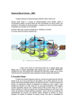
Specifications are subject to change without notice. 05/2004
X OttavoLib8053A (Apr/04)
23 06 2004
14:57
Pagina 2
X OttavoLib8053A (Apr/04)
23 06 2004
14:57
Pagina 3
PMM 8053A: THE ANSWER FOR ALL ENVIRONME
WHAT IS IT ?
Elettrosmog is a popular term used to describe
any phenomena or problem associated with artificially generated electric and magnetic pollution.
Any electric or electronic device may cause an
environmental risk.
All motors, electronic workstations, AM or FM
broadcasting transmitters, ovens, production
machinery, TV or cellular stations and even an
electrical wiring can generate potentially dangerous electric or magnetic fields.
POWER DISTRIBUTION
RISK CONSIDERATION
Anybody, as an employee or population, could be
exposed to fields high enough to be a danger to
health. Several studies confirm the risk of being
radiated by high magnetic or electric fields, many
papers have been written and doctors confirm
their findings.
In fact, IEC, ICNIRP, WHO, CENELEC and individual national agencies are now taking such
problems in to account, implementing new standards to protect workers and citizens world-wide.
All high voltage
power distribution systems have
the potential to produce
hazardous electric and magnetic fields. With the unique PMM 8053A electric sensor the measure of these
fields - doesn’t matter if they are very low or very high becomes easy, fast and precise.
IN THE FACTORY
PMM EXPERIENCE
PMM, with almost 10 years of experience
in this field, is active in several committees related to EM pollution. Thousands of
PMM field sensors have been installed
everywhere world-wide, measuring any
kind of fields from 10 Hz to 40 GHz.
RAILWAYS
Many types of production eq
(industrial ovens, RF dryers, sold
equipment, induction furnaces, etc.) u
frequency to operate. All these are potent
ces of electric or magnetic fields that could be
dangerous for health. High fields must be monitored
whenever possible, reduced and controlled to provide
working environment.
All trains, metros and similar means of transport use high
power devices and a lot of regulating electronic circuitry.
Eventually, high electrical and magnetic fields are generated
inside the passenger compartments, in the locomotive and
along the railways when the train passes.
The PMM 8053A offers a simple and portable measurement
system to collect data and enter associated report text, to
describe the location where the data has been gathered.
Back in the office, the information can be easily downloaded
into any PC to produce a nice and complete test report.
Thanks to the Spectrum analysis capability offered by
EHP-50A sensor, you can discriminate the 16,66 Hz of the
train or 50/60 Hz generated by the mains power line.
WHILE TRAVELLING
While driving along the roads it is possible to pass under
power distribution lines, close to broadcasting towers or
through tunnels where RF repeaters operate. All these sources can generate very high electromagnetic fields at levels
which could be unsafe for the body or potentially interfering
with the on board electronic.
X OttavoLib8053A (Apr/04)
23 06 2004
14:57
Pagina 4
MENTAL ELECTROMAGNETIC MEASUREMENTS
PMM SOLUTION
The PMM 8053A is the perfect solution
for monitoring electric and magnetic
fields everywhere: outdoors, at the workplace or at home.
BROADCAST AND TELECOM
TRANSMITTERS
POWER LINE MAGNETIC FIELDS
n equipment
soldering
tc.) use RF
tential sourd be quite
red and,
vide a safe
Whenever
a current flows, a magnetic field is generated. For
instance, electric appliances, tools, machineries
and power line transformers produce magnetic
fields at power line frequency
(50 or 60 Hz). With the unique PMM 8053A
magnetic sensor the measure of these fields
- doesn’t matter if they are very low or very high becomes easy, fast and precise.
Nowadays,
public and
private
broadcasting
and telecom stations cover
virtually every single piece of
land over all territories. Unless they
are protected, all these transmitting stations can be a potential danger for those leaving nearby or who are involved with their service
and maintenance. Thanks to its light weight and
acoustic alarm feature the PMM 8053A can be used
to monitor these electromagnetic fields against
exceeding safety thresholds.
PMM GLOBAL PARTNER
ISO 9001 certification and SIT calibrations offer a reliable, easy to use and
accurate instruments.
CELLULAR PHONES
HOSPITALS
Communications using cellular
phones is becoming more and more
popular. The ability to be reached
everywhere at any time is highly convenient
but not without some risks.
Measurements are quick and easy with the new
PMM 8053A.
Hospitals and surgeries are a very
delicate environment for our care and
health and need to be carefully protected.
The latest electronic medical devices are highly
sensitive to electromagnetic fields and patients
need to be defended against any accidental electromagnetic risk. The PMM 8053A provides a continuous
monitoring system and alarm for your peace of mind.
X OttavoLib8053A (Apr/04)
23 06 2004
14:57
Pagina 5
PMM 8053A - POWERFUL,
PMM is an official certified calibration lab (SIT 08)
within the Italian Calibration Scheme (SIT)
The PMM laboratory, traceable to Italian Metrological
Institute, features high performance equipment to deliver
test certificates
with the highest
confidence in the
results of the calibrations.
The use of automatic calibration procedures allows PMM
to calibrate the field
sensors in a minimum time,
giving precise and
low calibration cost
with a fast
turnaround time.
The PMM 8053A is
a state of the art
instrument.
Thanks to its
powerful
microprocessor and
large graphic display
it achieves high performances combined with small dimensions and simplicity of use.
The internal architecture uses three high density circuit boards which are easy to replace and repair.
The internal firmware is loaded through a PC and can be easily updated by downloading the newest
release via Internet from the PMM WebSite.
Convenient
alphanumeric
keyboard
Tripod
connection
Battery charger input.
Any DC from 10 to 15 VDC
Two RS232
interfaces
(wire and optical)
Fiber optic input/output for
additional sensor probes
LIGHT AND EASY TO USE
BENEFITS
• Precise measurements
• High confidence of correct operation
• Greatest accuracy
• Highly reliable measurements
• Plenty of data available simultaneously
• High resolution
• Field data can be evaluated by different types of user for
different applications
• Accurate perception of fluctuating field levels
• Entering of information about data and location report
• Operations interference free and with higher user safety
• Personal safety operation
• Easy to save different data with comments and setups
according to location where data are gathered
• Easy way to manipulate data and generate reports
• Minimum troubles with battery
• Long data acquisition
• Battery saving
PMM 8053A MAIN FEATURES
• Three axis probes
• Automatic antenna diodes checking
• Internal Calibration data
• Low frequency filters
• Large graphic LCD display (7x7 cm)
• Dynamic range >140 dB
• Arithmetic, Quadratic and Spatial averaging
(30s, 1, 2, 3, 6, 10, 12, 30 min. etc.)
• Analog indication (lin & log scale)
• Alphanumeric keyboard
• Fiber optic output
• Acoustic and display blinking alarm
• Labelled and partitioned internal memory
(32.700 readings)
• Acquisition software
• Battery status
• Optical repeater
• Programmable auto-off
• Two years warranty
Two years recalibration cycle
• Low maintenance cost
PMM EP-330
Three axis Isotropic probe
with internal E2PROM
storing all calibration data
Battery status
Probe used
Date of calibration
Probe
Status
EP 330
28 09 98
930.0 MHz
6.02 V
1s
Linear or logarithmic
analog indication
Three axis in
absolute or
relative values
12.64 V/m
300
Selection of modes:
• Average
• Spatial
• PC transfer
• Autocheck
• Comment
• Graph
UNIT
Units selection
Alarm
threshold
MODE
SET
Contrast control
PMM EP-44M
ELECTRIC FIELD PROBE
Technical specifications
Frequency range
Level range
Overload
Dynamic range
Resolution
Sensitivity
Absolute error @ 50 MHz
and 6 V/m
Flatness
(10 MHz - 200 MHz)
(200 MHz - 800 MHz)
Isotropicity
Out band attenuation respect
to 50 MHz - 900 MHz - 3 GHz
Temperature error
H-field rejection
Calibration
Size
Weight
Typical frequency response for EP-44M
100 kHz - 800 MHz
0,25 - 250 V/m
> 500 V/m
> 60 dB
0,01 V/m
0,25 V/m
± 0,8 dB
± 1,5 dB (Typical ± 0,8 dB)
± 2,0 dB (Typical ± 1,5 dB)
± 0,8 dB (Typical ± 0,5 dB
@ 740 MHz)
Typical linearity for EP-44M
> 12 dB (Typical > 15 dB)
0,02 dB/°C
> 20 dB
internal into E2PROM
317 mm length, 58 mm ø
100 g
PMM EP-300
ELECTRIC FIELD PROBE
Typical linearity for EP-300
Typical frequency response for EP-300
Technical specifications
Frequency range
Level range
Overload
Dynamic range
Resolution
Sensitivity
Absolute error @ 50 MHz
20 V/m
Flatness
(10 - 300 MHz)
(3 MHz - 3 GHz)
Isotropicity
H-field rejection
Temperature error
Calibration
Size
Weight
100 kHz - 3 GHz
0,1 - 300 V/m
> 600 V/m
> 66 dB (Typical >70 dB)
0,01 V/m
0,15 V/m (Typical >0,1 V/m)
± 0,8 dB
± 0,5 dB
± 1,5 dB
± 0,8 dB (Typical ± 0.5 dB @ 930
and 1800 MHz)
>20 dB
20°C÷60°C = ± 0,1 dB
0°C÷20°C = -0,05 dB/°C
-20°C÷0°C = -0,15 dB/°C
internal into E2PROM
317 mm length, 58 mm ø
100 g
ACCREDITED CALIBRATION CENTER SIT 08
Calibration of field strength sensors
In the frequency range 5 Hz to 400 MHz four Transverse
Electromagnetic (TEM) cells are used to produce calculable electric
and magnetic field strengths. In the frequency range 400 MHz to 40
GHz measurements are carried out inside an anechoic chamber
(5,5 m x 4 m x 3,5 m).
The electromagnetic field
is obtained by using
synthesised signal generators
opportunely amplified.
The output signal is
transferred into adequate
aperture antennas
(“Open Ended Guide” and
“Pyramidal Standard Gain
Horn”).
PMM OR-03 PROGRAMMABLE OPTICAL REPEATER
The PMM OR-03 is a programmable optical repeater which enables the connection of every
8053A probe (electric and magnetic fields) to the user's Personal Computer via an optical fiber
cable.
The OR-03 is an easy programmable device mainly designed for EMC applications together with
the SW-03 or WIN-OR-03 software or with a software developed directly by the user.
Technical specifications
Output
connector for optic fiber
(maximum length of optic
fiber, 80 m)
Input
Fischer connector for
PMM probes
Data output
X, Y, Z axis and total field;
probe model
and calibration date; frequency
correction value; battery voltage
and filter used
Compatibility
with all PMM 8053A probes,
SB-04 and SB-10
Programmability all functions are programmable
Internal battery
rechargeable NiMH batteries
(5 x 1,2 V)
Operating time
> 48 - 72 hours
(depends on the filter selected)
10 Hz filter > 72 hours
20 Hz filter > 61 hours
40 Hz filter > 53 hours
80 Hz filter > 48 hours
Recharging time < 4 hours
External power
supply
DC, 10 - 15 V, I = around 300 mA
Self testing
automatic function checks
during switch-on; automatic connection check of the instrument;
automatic check of each
individual sensor diode
Operating temperature
Storing temperature
Dimensions
Weight
from -10 to +40°C
from -20 to +70°C
130 mm x 55 mm ø
270 g
Standard accessories included
Battery charger
8053-BC
Plug international adapter
Optical converter RS232 8053-OC
Optical fiber cable (10 m) FO-8053/10
Conical Tripod support
Software diskette
WINOR03
PMM 8053-GPS
AUTOMATIC GLOBAL
POSITIONING SYSTEM
PMM 8053-GPS is an Optional Accessory for the PMM 8053A
system or SB-04 that enables the co-ordinates of the positions
where measurements are taken to be shown on the display of
the PMM 8053A meter or acquired by SB-04 into the PC.
It is especially useful in mapping a field over an area as the user can accurately assign the
position of each measurement taken. When the system is mobile, at a speed exceeding 3 km
an hour, the speed of movement and the direction in degrees (compass function) are also
available. PMM 8053-GPS can be used with the PMM SW02 Data Acquisition Software and
with the SB-04 Switching Control Box, in which case the program displays further accessory
data relating to the satellites of the GPS system, useful for verifying the location of antennas.
PMM 8053-GPS General specifications
Control Software
Internal within the PMM 8053A (from Version 2.08) or the
PMM SW02 (from Version 1.40)
SA On, PDOP =2.5
SA Off, PDOP < 2.5
Precision of Horizontal indication
100 m
< 23 m
Precision of Vertical indication
56 m
< 23 m
Precision of Time indication
340 ns
< 340 ns
Simultaneously managed satellites
8 in view
Resolution
1" time and 0.01" of ° lat/.long
(corresp. to abt 0.3 m/lat and 0.2 m/lon)
Internal battery
rechargeable NiMH batteries (5 x 1.2 V)
Operating time
> 12 hours
Recharging time
< 4 hours
External DC supply
DC, 10 - 15 V, I = about 400 mA
Fiber optic connection
up to 40 meters
Firmware update
update available through the serial port
Autocheck
automatically when switched on
Operational temperature
-10 to +40°C
Storage temperature
-20 to +70°C
Size (WxHxD)
100 mm x 100 mm x 115 mm
Weight
700 g
Differential GPS
DARC BTA R003 Standard RTCM SC 104 Ver. 2.1
Geodetic System
WGS-84
Standard Accessories included
•FO-8053/10 Fiber optic cable (10m)
•8053-BC Battery charger
•International power supply adapter
ELECTRIC FIELD PROBE
EP-33A
Typical frequency response for EP-33A
Technical specifications
Frequency range
Level range
Overload
Dynamic range
Resolution
Sensitivity
Absolute error @ 942.5 MHz
2 V/m
Flatness (925 - 960 MHz)
OFF Band attenuation
respect to 942.5 MHz:
860 MHz
1025 MHz
Isotropicity
Typical frequency response for EP-33A
925 MHz - 960 MHz
0,03 – 30 V/m
> 120 V/m
> 60 dB
0,001 V/m
0,03 V/m
± 1 dB
+ 0,2 dB / -1,8 dB
> 10 dB
> 10 dB
± 0,8 dB
(Typical ± 0,5 dB)
H-field rejection
> 20 dB
Temperature error
0°C ÷ 60°C = ± 0,2 dB
-20°C÷0°C = -0,1 dB/°C
Drift Frequency Vs Temperature 40°C ÷ 60°C = ± 100 kHz
-20°C÷40°C
= -100 kHz/°C
2
Calibration
E PROM internal
Size
317 mm length
58 mm ø
Weight
100 g
This test is carried out with a signal currently
used in laboratory for maximise the reading
error to make a comparison of the performances
of the probe with a common base.
Actually the radiobase station use eight time
slot of each channel so the effective error
of the measurement is negligible.
ELECTRIC
FIELD PROBE
EP-33B
Technical specifications
Frequency range
Level range
Overload
Dynamic range
Resolution
Sensitivity
Absolute error @ 1842,5 MHz
2 V/m
Flatness (1805 - 1880 MHz)
OFF Band attenuation respect
to 1842.5 MHz:
1580 MHz
2010 MHz
Isotropicity
H-field rejection
Temperature error
Drift Frequency
Vs Temperature
Calibration
Size
Weight
Typical amplitude response for a
GSM 1 frequency channel, 1 time
slot EP-33A
1805 MHz – 1880 MHz
0,03 – 30 V/m
> 120 V/m
> 60 dB
0,001 V/m
0,03 V/m
Typical frequency response for EP-33B
± 1 dB
+ 0,2 dB / -1,8 dB
> 10 dB
> 10 dB
± 0,8 dB
(Typical ± 0,5 dB)
> 20 dB
0°C ÷ 60°C = ± 0,2 dB
-20°C÷0°C = -0,1 dB/°C
40°C ÷ 60°C = ± 100 kHz
-20°C÷40°C = -100 kHz/°C
E2PROM internal
317 mm length, 58 mm ø
100 g
Typical frequency response for EP-33C
Typical frequency response for EP-33C
ELECTRIC FIELD PROBE
EP-33C
Technical specifications
Frequency range
Level range
Overload
Dynamic range
Resolution
Sensitivity
Absolute error @ 2140 MHz 2 V/m
Flatness (2110 - 2170 MHz)
OFF Band attenuation
respect to 2140 MHz:
1880 MHz
2320 MHz
Isotropicity
H-field rejection
Temperature error
Drift Frequency Vs Temperature
Calibration
Size
Weight
2110 MHz – 2170 MHz
0,03 – 30 V/m
> 120 V/m
> 60 dB
0,001 V/m
0,03 V/m
± 1 dB
+ 0,2 dB / -1,8 dB
> 10 dB
> 10 dB
± 0,8 dB (Typical ± 0,5 dB)
> 20 dB
0°C ÷ 60°C = ± 0,2 dB
-20°C÷0°C = -0,1 dB/°C
40°C ÷ 60°C = ± 100 kHz
-20°C÷40°C = -100 kHz/°C
E2PROM internal
317 mm length, 58 mm ø
100 g
Typical frequency response for EP-330
PMM EP-330
ELECTRIC FIELD PROBE
Technical specifications
Frequency range
Level range
Overload
Dynamic range
Resolution
Sensitivity
Absolute error @ 50 MHz
and 20 V/m
Flatness (10 to 300 MHz)
Flatness (3 MHz to 3 GHz)
Isotropicity
H-field rejection
Temperature error
Calibration
Size
Weight
Typical isotropic response for EP-330
100 kHz - 3 GHz
0,3 - 300 V/m
> 600 V/m
> 60 dB
0,01 V/m
0,3 V/m
± 0,8 dB
± 0,5 dB
± 1,5 dB
± 0,8 dB (Typical ± 0.5 dB)
>20 dB
20°C ÷ 60°C = ±0,1 dB
0°C ÷ 20°C = -0,05 dB/°C
-20°C ÷ 0°C = -0,15 dB/°C
internal into E2PROM
317 mm length, 58 mm ø
100 g
EP-330-Typical amplitude reponse for two CW
signal of same level
Typical linearity for EP-330
PMM HP-102
MAGNETIC FIELD PROBE
Typical isotropic response for HP-102
Typical linearity for HP-102
Technical specifications
Frequency range
Level range
Overload
Dynamic range
Resolution
Sensitivity
Absolute error @ 50 MHz
and 2 A/m
Flatness (50 - 900 MHz)
Isotropicity
E-field rejection
Calibration
Temperature error
Size
Weight
30 - 1000 MHz
0,01 - 20 A/m
> 40 A/m
> 60 dB
1 mA/m
0,01 A/m
± 1 dB
± 1 dB
± 0,8 dB (Typical
± 0,5 dB @ 930 MHz)
> 20 dB
internal into E2PROM
0,05 dB/°C
317 mm length, 58 mm ø
110 g
Typical frequency response for HP-102
PMM EP-105
ELECTRIC FIELD PROBE
Technical specifications
Frequency range
Level range
Overload
Dynamic range
Resolution
Sensitivity
Absolute error @ 50 MHz
and 6/Vm
Flatness (10 - 300 MHz)
Flatness (300 kHz - 1 GHz)
Isotropicity
H-field rejection
Calibration
Temperature error
Size
Weight
Typical frequency response for EP-105
100 kHz - 1000 MHz
0,05 - 50 V/m
> 100 V/m
> 60 dB
0,01 V/m
0,05 V/m
± 0,8 dB
± 0,5 dB
± 1 dB
± 0,8 dB (Typical ± 0,5 dB
@ 930 MHz)
> 20 dB
internal into E2PROM
0,05 dB/°C
350 mm length, 133 mm ø
290 g
Typical linearity for EP-105
Typical isotropic response for EP-105
PMM HP-032
MAGNETIC FIELD PROBE
Typical frequency response for HP-032
Technical specifications
Frequency range
0,1 - 30 MHz
Level range
0,01 - 20 A/m
Overload
> 40 A/m
Dynamic range
> 60 dB
Resolution
1 mA/m
Sensitivity
0,01 A/m
Absolute error @ 1 MHz and 2 A/m ± 1 dB
Flatness (1 - 25 MHz)
± 1 dB
Isotropicity
± 0,8 dB (Typical ± 0,5 dB
@ 1 MHz)
E-field rejection
> 20 dB
Calibration
internal into E2PROM
Temperature error
0,05 dB/°C
Size
350 mm length, 133 mm ø
Weight
400 g
PMM EP-183
MICROWAVE ELECTRIC PROBE
Technical specifications
Frequency range
Level range
Overload
Dynamic range
Resolution
Sensitivity
Absolute error @ 200 MHz
and 6 V/m
Flatness (1 MHz - 1 GHz)
(1 GHz - 3 GHz)
(3 GHz - 18 GHz)
Isotropicity at 200 MHz
Temperature error
H-field rejection
Calibration
Size
Weight
Typical frequency reponse for EP-183
1 MHz - 18 GHz
0,8 - 800 V/m
> 1200 V/m
60 dB
0,01 V/m
0,8 V/m
± 0,8 dB
± 1,5 dB
± 2,0 dB
± 2,5 dB
± 0,8 dB (Typical ± 0,5 dB @ 930 and 1800 MHz)
0,02 dB/°C
> 20 dB
internal into E2PROM
317 mm length, 50 mm ø
90 g
Typical isotropic response for EP-183
PMM EP-33M
ELECTRIC FIELD PROBE
Typical isotropic response for EP-33M
All probes can be mounted
directely to PMM 8053A or via
fiber optic using the optical
repeater OR-03
Typical frequency response for EP-33M
Technical specifications
Frequency range
Level range
Overload
Dynamic range
Resolution
Sensitivity
Absolute error @ 930 MHz
and 20 V/m
Flatness (900 MHz - 3 GHz)
Isotropicity @ 930 MHz
Temperature error
H-field rejection
Calibration
Size
Weight
Typical linearity for EP-33M
700 MHz - 3 GHz
0,3 - 300 V/m
> 600 V/m
> 60 dB
0,01 V/m
0,3 V/m
± 1 dB
± 1,5 dB
± 0,8 dB (Typical ± 0,5 dB)
0,05 dB/°C
> 20 dB
internal into E2PROM
317 mm length, 58 mm ø
100 g
PMM EP-408
ELECTRIC FIELD PROBE
Technical Specifications
Frequency range
Level range
Overload
Dynamic range
Resolution
Sensitivity
Absolute error @ 200 MHz
and 6 V/m
Flatness (1 MHz - 1 GHz)
(1 GHz - 3 GHz)
(3 GHz - 18 GHz)
(18 - 26,5 GHz)
(26,5 - 40 GHz)
Isotropicity @ 200 MHz
Temperature error
H-field rejection
Calibration
Size
Weight
Typical frequency response for EP-408
1 MHz - 40 GHz
0,8 - 800 V/m
> 1000 V/m
> 60 dB
0,01 V/m
0,8 V/m
± 0,8 dB
± 1,5 dB
± 2,0 dB
± 2,5 dB
± 3 dB
± 4 dB
± 0,8 dB (Typical ± 0,5 dB)
0,02 dB/°C
> 20 dB
internal into E2PROM
317 mm length, 52 mm ø
90 g
Typical isotropic response for EP-408
Typical linearity for EP-408
PMM EP-301
ELECTRIC FIELD PROBE
Typical isotropic response for EP-301
Typical linearity for EP-301
Technical Specifications
Frequency range
Level range
Overload
Dynamic range
Resolution
Sensitivity
Absolute error @ 50 MHz
and 20 V/m
Flatness (10 - 300 MHz)
Flatness (3 MHz - 3 GHz)
Isotropicity @ 930 - 1800 MHz
Temperature error
H-field rejection
Calibration
Size
Weight
100 kHz - 3 GHz
1 - 1000 V/m
> 1200 V/m
> 60 dB
0,1 V/m
1 V/m
± 0,8 dB
± 0,5 dB
± 1,5 dB
± 0,8 dB (Typical ± 0,5 dB)
0,05 dB/°C
> 20 dB
internal into E2PROM
317 mm length, 58 mm ø
100 g
Typical frequency response for EP-301
PMM HP-050 & HP-051
MAGNETIC FIELD PROBE
Technical specifications
Frequency range
Level range
Overload
Dynamic range
Resolution
Sensitivity
Absolute error @ 50 Hz 25 °C
Flatness (40 Hz - 1 kHz)
Isotropicity @ 50 Hz
Temperature error
E-field rejection
Calibration
Size
Weight
HP-050
HP-051
10 Hz - 5 kHz
10 Hz - 5 kHz
10 nT - 40 µT
50 nT - 200 µT
400 µT
400 µT
> 72 dB
> 72 dB
1 nT
1 nT
10 nT
50 nT
± 0,4 dB @ 200 nT
± 0,4 dB @ 3 µT
± 1 dB
± 1 dB
± 0,3 dB @ 200 nT
± 0,3 dB @ 3 µT
0,015 dB/°C
0,015 dB/°C
> 20 dB
> 20 dB
internal into E2PROM
350 mm length, 133 mm ø
400 g
Typical frequency response for HP-050
PMM 8053-SW02 - DATA ACQUISITION SOFTWARE
PMM SW02 Software is a computer tool that enhances 8053A performances. By means of a simple interface between
the meter and the PC, SW02 software broadens the flexibility of use of 8053A by facilitating the acquisition, storage,
and graphic and numeric display of the data collected.
Basic functions
• It acquires the readings taken with PMM 8053A or with SB-04 and records the data at sampling intervals of one second for the
time duration defined by the user.
• It permits the readings that have been taken to be saved, at the same time, as both an envelope and as an individual data and,
later on, to be retrieved and analysed.
• It permits the data of the measurements stored in the Logger of PMM 8053A to be downloaded and saved in files and be
displayed graphically.
• It makes a graphic representation of the envelope of the stored and/or saved readings, permitting moment by moment analysis of
values with the aid of a marker.
• It permits the measured values to be compared with the limits imposed by the user.
• It permits the readings in progress to be graphically and numerically displayed in real time.
• The files saved on disk, relating to the measurements taken, are recorded with the date and time of measurement and any other
useful reference information added by the user, enabling a measurement database to be created very easily. Furthermore, they
lend themselves to additional processing with
other external programs or spreadsheets,
such as Excel™ etc.
• A simple user interface based on the Windows™ Operating System
makes its use intuitive and user-friendly.
• The connection between the field meter and the computer via serial
cable (used for the connection with 8053A or SB-04) or via fiber
optics (only when using 8053A or OR03), guarantees maximum
security and flexibility in link-up in all operating conditions.
E (V/m) H (A/m)
1
2
5
6
10
20
30
50
100
200
300
500
1000
PMM SB-04 - SWITCHING
CONTROL BOX
Technical Specifications
Compatibility
With all 8053A sensors via OR-02/OR-03 optical
repeater or directly (when sensor has
its own internal optical repeater)
Input
4 fiber optical connector
Interfaces
RS232 for PC connection
and one expansion connection
Internal battery
Rechargeable NiMH
batteries (5x1,2 V)
Operating time
> 10 hours
Recharging time
< 12 hours
External DC supply
DC, 10 – 15 V, I= about
200 mA
Optic Fiber connection
Up to 80 m long
Internal Firmware update Customer upgrade
available via serial
connection
Self test
Automatic during
switching-on
operation
Conformity
To directive 89/336
and 72/23 and
amendments
Operating temperature
-10 to +40°C
Storage temperature
-20 to +70°C
Size
25 x 148 x 220 mm
Weight
900 g
Software
included
Here you can find
some example of SB-04
interconnections:
0,0027
0,0053
0,0133
0,0159
0,0265
0,0531
0,0796
0,1326
0,2653
0,5305
0,7958
1,3263
2,6525
S (W/m2)
0,0027
0,0106
0,0663
0,0955
0,2653
1,0610
2,3873
6,6313
26,5252
106,1008
238,7268
663,1300
2652,5199
S (mW/cm2) Conversion Tables
0,00027
0,00106
0,00663
0,00955
0,02653
0,10610
0,23873
0,66313
2,65252
10,61008
23,87268
66,31300
265,25199
Depending on the norm or
standard adopted, there is the
need to frequently change from
using one measuring unit to
another. PMM 8053 can
automatically perform the
conversion. The following table
offers a convenient way to
calculate equivalent values in
far-field conditions.
The relationships are:
H (A/m = E (V/m)/377
S (W/m2) = E (V/m) x H (A/m)
The PMM SB-04 Switching
Control Box is a versatile and
expandable accessory to monitor, simultaneously, electric
and magnetic fields from 5 Hz
up to 40 GHz. Thanks to GPS
option, you can also measure
the position of your system.
Either PMM 8053A or all its
field probes equipped with the
optical repeater OR-02/03,
and EHP-50A/B/C analyzers
are supported.
L
X-OttavoLib8053A (Apr/04)
L,
29-06-2004
12:22
Pagina 6
PMM EHP-50C
ELECTRIC AND MAGNETIC
FIELD ANALYZER FROM 5 Hz UP TO 100 kHz
Technical specifications
Frequency range
Level range
Overload
Resolution
Resolution
Sensitivity
Absolute error
Linearity @ 50 Hz
Magnetic field rejection
Electric field rejection
Electric field
5 Hz – 100 kHz
0,01 V/m – 100 kV/m
200 kV/m @ 50Hz
0,001 V/m (on 8053 display)
0,1 V/m (with 8053 data logger)
0,01 V/m
± 0,5 dB
(@ 50 Hz and 1 kV/m)
± 0,2 dB (1 V/m - 100 kV/m)
> 20 dB
Magnetic field
5 Hz – 100 kHz
1 nT – 10 mT
20 mT @ 50Hz
1 nT (on 8053 display 8053 or
EHP-50C internal data logger)
10 nT (with 8053 data logger)
1 nT
± 0,5 dB
(@ 50 Hz and 0,1 mT)
± 0,2 dB (200 nT - 10 mT)
w
e
N
>20 dB
General specifications
Internal memory (with span
higher than 200 Hz)
1440 data with 1 minute storing;
2880 data with 30 sec storing;
the data can be transferred only to PC
Internal data logger
1 measurement every 30 or 60 seconds
Dynamic
> 140 dB
FFT Spectral analysis
FFT Spectral analysis
Start frequency
1,2% of the SPAN
Stop frequency
same of the SPAN
SPAN
100, 200, 500 Hz;
1 2 10 100 kHz
Flatness (40 Hz - 10 kHz)
± 0,5 dB
Isotropicy
± 1 dB
Calibration
Internal on E2PROM
Temperature error
0,05 dB/°C
Size
96 x 96 x 115 mm
Weight
about 525 g
Internal battery
rechargeable NiMH (5 x 1,2V)
Maximum connection distance via fiber optic
80 m
Operating temperature
-10 / +40 °C
and later it would be possible to download all data to the PC.
From PC it is possible to select if to measure the electric or
magnetic field, to select the full scale, the Highest or Wideband
mode, the SPAN wished and the sampling intervals 1 per minute
or 1 per 30 seconds.
Some typical applications are:
• Magnetic fields near high, medium and low voltage transformers
• Measurements in proximity of power line towers
• Safety measurement at worker’s site
• Measurements close to machinery, air conditioning systems,
home appliances, etc.
• Development of new products
PMM EHP-50C offers a powerful and low
cost solution to continuous monitoring of
the electric and magnetic fields.
The EHP-50C analyzer has 3 modes
of operations:
• Stand alone mode without any external
apparatus connection
• Connected to 8053A via fiber optic
• Connected to a Pocket PC via fiber optic
Once the measurement parameters have been
programmed thru a PC, the EHP-50C analyzer
can start its acquisition by storing the data over
24 hours in stand alone mode. It is necessary to
set it over the TR-02A tripod and to activate the
start. After 24 hours it will automatically stop
EHP-50C analyzer connected to 8053A has two modes for storing
data. The normal mode will store the highest value included
between the sampling interval; in Low Power (Def LP) mode
EHP-50C will store the instantaneous value during the turn on
process.
SPAN
Typical
operation
time in
Normal mode
(hours)
Time that
EHP-50C
is ON
(sec.)
Battery
operation time
in Low Power
mode with Data
logger set at
60 sec (hours)
Battery
operation time
in Low Power
mode with Data
logger set at
300 sec (hours)
100 Hz
200 Hz
500 Hz
1 kHz
2 kHz
10 kHz
100 kHz
>11
>11
>10
>10
>9
>6
>9
25
15
8
5
5
5
4.5
>24
>36
>48
>72
>65
>60
>72
>72
>110
>130
>150
>150
>130
>150
X OttavoLib8053A (Apr/04)
23 06 2004
14:57
Pagina 7
EHP-50C with Pocket PC
It is possible to connect the EHP-50C to
HP iPAQ Pocket PC h 2210 via fiber
optic, by using the provided software
supplied on SD memory card. With
this configuration is only possible to
perform punctual measurements
and get the spectrum analysis.
The field shown is either in digital or analogic form with indication of the battery status.
The real time spectrum
analysis offers the capability to see and to
measure all 50/60 Hz
Optical fiber
harmonics together
with the frequency and
related field levels
included inside the selected SPAN.
The spectrum can be stored
in TXT format and later on
printed, manipulated or transferred to a PC.
Reading
Frequency
(narrow only)
Setting’s
frequency
span
Setting’s
field scale
Digital
reading
Analog
meter
Max
reading
marker
User
marker
Options bar
Wide - Narrow
selection
EHP-50 Battery
status
Features
• Save:
to save the spectrum in TXT
format (table of all frequencies
and levels)
• Probe Settings:
to configure the EHP-50C to
measure electric or magnetic
fields and to define the SPAN
• Options:
to select the serial port
• Exit:
to exit the program
• The Marker function:
8053
OC/OL232
allows to perform peak or differential measurements (Delta)
• Delta peak:
RS232
with the pen of the Pocket PC it
Adaptor
is possible to position a second
Marker in every position of the
spectrum to perform differential
measurements
• With the Pocket PC:
it is not possible to get the data
logger function (field versus time)
EHP-50 battery
status
EHP-50C with 8053A
The system composed by 8053A+EHP-50C offers
many additional features to perform different
kind of acquisition and data logging until several
days of continuous monitoring.
From the 8053A Setup menu is possible to choose
several kind of data acquisition modes by using
all 8053A features (data logger of 8053A).
On 8053A display it is possible to show the spectrums and save them inside its memory (up to 64
spectrums). By using the Marker it is possible to
measure an individual frequency component, and in data logger mode is possible
to store only the selected frequency over
the time domain with a sample rate definable by the user.
w
e
N
Accessories supplied with EHP-50C
•
•
•
•
•
•
•
•
Battery charger
Fiber optic: 10m
Optical to serial converter 8053-OC
Optical short loop
Mini Tripod
Software to be installed on PC
Calibration Certificate
User manual
Optional Accessories
EHP-50PALM kit is composed by:
• RS232 cable with adapter for HP iPAQ
Pocket PC h 2210
• Optical to serial converter 8053-OC
• 32 Mb SD memory with installed PMM
software
• User manual
Marker
Frequency
SPAN
Marker
indicator
Field corresponding
to the Marker
X OttavoLib8053A (Apr/04)
23 06 2004
14:58
Pagina 8
OPTIONAL ACCESSORIES
▼
A wide range of accessories is available to help the user to perform
accurate and reliable measurement.
PMM SB-10 SWITCHING CONTROL BOX
The PMM SB-10 Switch Control Box is a versatile and
expandable accessory for the PMM electric and magnetic
fields and electrosmog measurement devices family.
Either the PMM 8053A Portable Field Strength Meter
and the OR-03 Optical Repeater with all their field probes are supported.
The EHP50/A/B/C are not supported.
One PMM SB-10 allows taking field measurement with
up to 10 measuring devices connected at the same time,
either placed in different measuring points and/or
working on different frequencies and full scale ranges. It
is possible to have a chain composed by up to five SB-10
to connect up to 50 remote devices.
One PMM SB-10 allows to connect up to ten devices via
optical fiber to the Personal Computer by a single RS232
interface connection.
TR-02A TRIPOD
Wooden tripod with swivel
and soft carrying case
Height adjustable from
1 to 2 m.
Thread: 1/4” x 20
Size: 1 m (closed)
Weight: 3 kg
FO-8053 FIBER OPTIC
To increase the quality of the
measurement and to avoid
the influence of the operator,
it is possible to connect the
sensor to the PMM 8053A
via a fiber optic using the
dedicated optical repeater
OR-03.
The same fiber is used to
connect the PMM 8053A
to the PC equipped with
optical to serial converter 8053-OC.
Four sizes of fiber optics are available:
FO-8053/10: 10 m - FO-8053/20: 20 m
FO-8053/40: 40 m - FO-8053/80: 80 m
The standard accessories included with PMM SB-10 are:
• External DC supply (DC 12 V, 1,25 A)
• USB cable, type A-B (1.8 m long);
• RS232 serial cable (2 m long);
• SB-10 to SB-10 Expansion cable (20 cm long);
• Optic protection caps (20 pcs)
• Operating Manual;
• Certificate of Compliance;
• Return for Repair Form.
TT-01 TELESCOPIC SUPPORT
Fiberglas telescopic support for holding sensors or
optical repeater expandable from 1,15 to 4 m.
Size: 1,15 m (closed)
Weight: 0,6 kg
8053-CC RIGID
CARRYING CASE
This alluminium case has
been designed to carry
8053A with few probes
and accessories.
Size: 500 x 400 x 170 mm
8053-CAL
CALIBRATOR
This device, powered by
8053A, is useful to test the
functionality of 8053A’s X,
Y, Z input.
Readout on 8053A: 57,7 V/m
Accuracy: ± 2%
8053-TR REMOTE
TRIGGER
This device is used to
remote trigger the 8053A.
At each contact closure,
8053A takes and store a
reading. It is useful
together with the metric
wheel to associate a spatial
position to a field.
8053-OC RS232
OPTICAL CONVERTER
This device allows to
translate the light coming
out from the fiber into a
RS232 signal for PC.
X-OttavoLib8053A (Apr/04)
29-06-2004
12:21
Pagina 1
PMM 8053A
GENERAL PURPOSE FIELD METER
(see specific probes for dedicated specs.)
Resolution
Sensitivity
Units
5 Hz – 40 GHz
> 140 dB (depending on sensor)
E-Field: 0,03 V/m to 100 kV/m
H-Field: 1 nT to 10 mT
0,01 to 100 V/m; 0,1 nT to 0,1 mT
0,1 to 1 V/m; 10 nT to 0,1 mT
V/m, kV/m, µW/cm2, mW/cm2,
W/m2, A/m, nT, µT, mT
LCD Display Function
Field measured
X, Y, Z in absolute values or %
and total are displayed
Time & Date
Internal real time clock
Sensor type
Model and calibration date
are shown
Graphic bar
An analog sliding bar (either linear
or logarithmic) will show:
- real time value with respect to
full scale
- field versus time with automatic
time scaling
- alarm threshold
Measuring Function
Measuring time
150 msec with 80 Hz filter
250 msec with 40 Hz filter
450 msec with 20 Hz filter
900 msec with 10 Hz filter
Internal memory
Up to 32.700 measurements
(8.100 standard memory,
21.600 extended memory)
Alarm
Variable threshold 0 to 100% full
scale. Internal sound and blinking
symbol on the display when the level
is greater than the alarm threshold
Function
Max., Min., Averaging
Averaging Mode
Arithmetic, quadratic (RMS),
manual, rolling average and
spatial over
Averaging time
Selectable from 30 sec, 1, 2, 3, 6,
10, 15, 30 min
Sampling mode (1, 10÷900 sec/sample)
Data Acquisition
(Logger)
Data change mode
(± 3 dB variation)
Over the limit mode
Average on 6 min
(1 or 6 min resolution)
Manual mode
Spectrum mode with EHP-50A/B/C
General Specifications
Output
LCD display 72 x 72 mm
128 x 128 pixel, RS232 or fiber optic
Input
Direct through Fischer connector
or via fiber optic connector
Internal battery
Rechargeable NiMH batteries
(5 x 1,2 V)
Operating time
> 24 hours in normal mode;
> 48 hours in save mode (display off)
Recharging time
External DC supply
Software update
Interface
Selftest
Calibration
Conformity
Operating temperature
Storage temperature
Tripod support
Dimensions (WxHxD)
Weight
Standard Accessories Included with 8053A
8053-SC
Soft carrying case
8053-BC
Battery charger
8053-RS232
Serial cable (1,5 m)
8053-SW01
Downloading software
8053-SW02
Acquisition software
8053-8000
Manual (Italian, English or French)
Optional Accessories
EP-300
EP-330
EP-301
EP-33A
EP-33B
EP-33C
EP-33M
EP-44M
EP-105
EP-183
EP-408
HP-032
HP-102
EHP-50C
HP-050
HP-051
8053-GPS
SB-04
SB-10
8053-RT
8053-CAL
FO-8053/10
FO-8053/20
FO-8053/40
FO-8053/80
TR-02A
8053-CC
8053-CA
TT-01
OR-03
8053-OC
Distributed by
Sales Office
Via L. da Vinci 21/23 • 20090 Segrate • Italy
Tel. +39.02.26952421 • Fax +39.02.26952406
Email: [email protected] • Internet: http://www.pmm.it
< 4 hours
(15 minutes charge = 1 hour
operation)
DC, 10 - 15 V, 500 mA
Free; via Internet
RS232 for remote operation
calibration and firmware update
Automatic during switch-on of all
functions. Automatic check of
each individual diode
Inside the built-in E2 PROM of the
sensor
To Directive 89/336 and 73/23
and amendments, etc.
-10 to +40°C
-20 to +70°C
Threaded insert 1/4”
108 x 240 x 50 mm
1,07 kg
Electric field 100 kHz - 3 GHz
Electric field 100 kHz - 3 GHz
Electric field 100 kHz - 3 GHz
Electric field 925 MHz - 960 MHz
Electric field 1805 MHz - 1880 MHz
Electric field 2110 MHz - 2170 MHz
Electric field 700 MHz - 3 GHz
Electric field 100 kHz - 800 MHz
Electric field 100 kHz - 1 GHz
Electric field 1 MHz - 18 GHz
Electric field 1 MHz - 40 GHz
Magnetic field 100 kHz - 30 MHz
Magnetic field 30 MHz - 1 GHz
Electric & Magnetic 5 Hz -100 kHz
Magnetic field 10 Hz - 5 kHz
Magnetic field 10 Hz - 5 kHz
GPS module
Automatic switching Box
Programmable switching Box
Remote trigger
Calibrator for 8053A
Fiber optic cable (10 m)
Fiber optic cable (20 m)
Fiber optic cable (40 m)
Fiber optic cable (80 m)
Tripod
Rigid carrying case
Car adapter
Telescopic support
Programmable optical repeater
RS232 optical converter
Specifications are subject to change without notice. 07/2004
Frequency Range
Frequency range
Dynamic range
Operating range