1
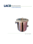
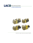
USER MANUAL
VACUUM DEGASSING CHAMBERS AND SYSTEMS
CONTACT US
PHONE/FAX
Toll Free: 800.465.1004
Phone: 801.486.1004
Fax: 801.486.1007
ADDRESS
LACO Technologies, Inc.
3085 West Directors Row
Salt Lake City, UT 84104
WEB
www.lacotech.com
[email protected]
SMT-09-1002 Rev A2
ii
© 2010 LACO TECHNOLOGIES, INC.
CONTENTS
1. SCOPE .................................................................................... 1
2. SAFETY .................................................................................. 1
3. COMPONENTS ..................................................................... 1
4. BASIC OPERATION .............................................................. 3
5. RECOMMENDED PROCEDURES ....................................... 4
6. APPENDIX A:
REMOVAL OF AIR FROM LIQUIDS ................................... 5
7. APPENDIX B:
CARING FOR ACRYLIC ........................................................ 8
8. APPENDIX C:
SPARE PARTS AND ACCESSORIES ................................... 9
iii
© 2010 LACO TECHNOLOGIES, INC.
LACO USER MANUAL - VACUUM DEGASSING CHAMBERS AND SYSTEMS
1. SCOPE
This manual outlines the components, safety information, recommended
maintenance for LACO Technologies Vacuum Degassing Systems.
Following these recommended procedures will ensure that your degassing
system is performing at its highest level. This manual also includes product
information for degassing systems, including accessories, options, and
spare parts.
1.1
MAKEUP OF A DEGASSING SYSTEM
A typical vacuum degassing systems includes a vacuum chamber
connected to a vacuum pump for removing trapped gases from
compounds. With the appropriate vacuum pump degas chambers are
used to reduce the pressure above the surface of the material and permit
escape and subsequent removal of entrapped air and other gases that
could induce failure of the final product. Degas chambers and pumps are
available with several options and accessories for a complete vacuum
degas system to meet your requirements.
2. SAFETY
2.1
VACUUM PUMP SAFETY
A complete manual will be provided for the vacuum pump and should
be referred to for safety issues relating to the specific vacuum pump
purchased.
2.2
VACUUM CHAMBER SAFETY
All degassing chambers are designed for holding full vacuum, but any
defects, cracks or severe wear should be reported to LACO for advisement.
Vacuum chambers are not designed for pressure applications. If slight
pressure is needed (5 psi or less) the chamber must be provided with
necessary clamps and pressure safety relief valves.
3. COMPONENTS
A vacuum degassing system comprises of two main items; a vacuum
chamber and vacuum pump. Several accessories and options can be
added to customize the degassing system. Systems are available in
modular configurations or as complete setups mounted onto carts or
stands.
1
© 2010 LACO TECHNOLOGIES, INC.
LACO USER MANUAL - VACUUM DEGASSING CHAMBERS AND SYSTEMS
3.1
VACUUM CHAMBERS
The most common vacuum degassing chamber is a cylindrical vessel,
fitted with a vacuum control valve, vacuum release valve, vacuum dial
gauge, “L” type gasket and a clear acrylic or metal lid.
The cost of cylindrical vacuum chambers tend to increase far more with
increases in diameter than length. Horizontal chambers will also be more
than corresponding vertical chamber due to the need for cradle supports
and lid hinging. This orientation is preferred if the product is easier to load
and monitor. A common option for horizontal chambers include shelf
support rails and removable shelves. Vacuum degas chambers are most
commonly made from 304 stainless steel however LACO offers vertical
chambers also in aluminum and clear acrylic for full viewing.
To select a chamber for your purpose, ensure that your container will fit
into the chamber with sufficient space to allow for expansion of the liquid
to be degassed. Initially, fill your container one quarter with mixture,
experience will show the limit of mixture level permissible.
3.2
VACUUM PUMP AND HOSE
Based on the application the vacuum pump can be the greatest cost and
the most critical component for successful degassing. Choices range from
dry membrane pumps capable of vacuum levels down to 60 Torr or 27
inHG for single stage models and 7 Torr or 29 inHG for two stage models.
These dry pumps have pumping speeds or cfm values ranging from 1 to
7 cfm. For higher vacuum levels and cfm values, oil sealed rotary vane
vacuum pumps are used. Single stage models are capable of vacuum down
to 0.5 Torr and cfm from 1 to 100 cfm. Two stage models are capable of
vacuum down to 0.005 Torr or 5 millitorr and range in cfm from 2 to 50 cfm.
When selecting a pump it is necessary fully degas the mixture before it
even begins to gel or set. Knowing the pot life of the material will help in
selecting the right speed or cfm of pump. The manufacturer of the material
may recommend a vacuum level based on the properties of the material. If
you are unsure of the vacuum level requirement it is always easier to have
more vacuum than less.
3.3
COMMON ACCESSORIES
• Vacuum traps protect the vacuum pump from contaminates during the
degassing process and also prevent backstreaming of pump oil into the
vacuum lines or chamber.
• Digital vacuum gauges with units in torr or millitorr to accurately
monitor and repeat the process at the same vacuum level.
• Chamber mixers with rotary shaft feedthroughs
2
© 2010 LACO TECHNOLOGIES, INC.
LACO USER MANUAL - VACUUM DEGASSING CHAMBERS AND SYSTEMS
• Chamber internal platen heaters
• Heating blankets can be fitted around the vacuum chamber to achieve
higher wall temperatures. Heaters are NOT suitable for use with clear
acrylic doors.
• Electrical and thermocouple feedthroughs
• Liquid feedthroughs and valves
4. BASIC
OPERATION
Degassing of a liquid mixture is the removal of air bubbles which become
entrapped in the mixture when mixing the components. See Appendix A
for a complete discussion on vacuum degassing. The following is a quick
review of procedures for removal of air bubbles from resin mixes, RTV
silicone and similar liquids.
1. Close the vacuum valve connected to the vacuum pump and switch
the vacuum pump ON and allow to warm up.
2. Open the vacuum release or vent valve and remove the chamber lid.
3. Mix the materials to be degassed in a suitable container not more that
1/3 to 1/2 full and place this container in the chamber.
4. Replace the lid, making sure it fully covers the gasket on the vacuum
chamber.
5. Close the vacuum release valve.
6. Open the vacuum valve.
7. Watch the mixture and the vacuum gauge. When the chamber is
undergoing the evacuation the mixture will begin to rise, slowly at
first. At nearly full vacuum the mixture will have swollen up to fill the
mixing vessel, air bubbles will appear and burst at the mixture surface.
After a few seconds, this mixture will collapse to near its original
volume. Occasional bubbles will appear at the surface.
8. If the mixture rises too fast and is likely to overflow the container then
momentarily reduce the vacuum by opening and closing the vacuum
release valve or closing the vacuum valve. Repeat if necessary.
9. Wait for about 30 seconds after the collapse and close the vacuum
valve.
3
© 2010 LACO TECHNOLOGIES, INC.
LACO USER MANUAL - VACUUM DEGASSING CHAMBERS AND SYSTEMS
NOTE
One can also monitor the time and vacuum level on the
vacuum gauge as well as the material, to determine the
length of time to hold it under vacuum. The length of
time to degas is highly dependent on the product and the
particular application. Often an absolute pressure vacuum
gauge is used to monitor the vacuum level of the system
and determine if gases or solvents are evolving from
the product. The vacuum chambers are equipped with a
relative 0-30 in HG vacuum gauge, which is mainly used
to determine a rough vacuum level. For more accurate
measurement and control of the process, contact LACO
about an absolute vacuum gauge.
10. Open the vacuum release valve and remove the lid.
11. Fill the mold(s) carefully to minimize trapped air.
12. If necessary, place the mold(s) into the vacuum chamber.
13. Repeat stages above as necessary.
14. Some bubble may appear at the mixture surface and burst.
15. Continue degassing for about 30 seconds at full vacuum.
16. Repeat steps 10, 11, 12.
5. RECOMMENDED
PROCEDURES
5.1
VACUUM PUMP OIL CHANGES
The vacuum pump is the most critical maintenance item in a degassing
system. For oil sealed rotary vane vacuum pumps the most critical
maintenance item is to change the pump oil frequently. The frequency
will depend on the application and usage but it is recommend that if the
oil ever turns cloudy, dark or is foul smelling, change it immediately. Any
degassed solvents, water or other liquids will condense in the pump oil
and lower the vacuum level the pump is able to achieve. Frequent oil
changes will also extend the life of the vacuum pump.
When changing pump oil it is recommended to also use a flushing fluid
to cleanse the pump. LACO’s LVOFF is a hydrocarbon fluid specifically
designed to assist in the internal cleaning of particles and sludge build-up
in mechanical vacuum pumps. Its low viscosity helps free contamination
from internal parts allowing it to be flushed from the pump through the
drain valve.
4
© 2010 LACO TECHNOLOGIES, INC.
LACO USER MANUAL - VACUUM DEGASSING CHAMBERS AND SYSTEMS
5.2
FLUSHING PROCEDURE
1. Drain the used fluid from the pump while still hot from operation and
refill with LVOFF.
2. Run the pump blanked off or isolated for approximately 20-30 minutes
or until pump is hot.
3. Drain the pump completely (open gas ballast and jog the pump to aid
in removing oil).
4. Repeat the procedure if necessary then refill with LACO 19 grade oil
for direct drive pumps of 195 grade for belt drive pumps or other oil as
specified.
WARNING
Any foreign material left remaining in the vacuum
chamber or vacuum hose lines can contribute to
outgassing and reduce the performance of the system and
the vacuum pump.
6. APPENDIX A:
REMOVAL OF AIR
FROM LIQUIDS
6.1
APPLICATIONS
• RTV Silicone Rubber
• Araldite
• Polyester Resin
• Plastasols
• Casting Plaster
• Polysulphide Rubber
• Polyurethane Resin
• Adhesive Mixes
• Epoxy Resins
• Investment Plaster
6.2
INTRODUCTION
When any of the above listed materials are mixed with the required
additives, accelerator, filler etc., then air bubbles can become trapped
within the mixture. If not removed before the material cures the air
bubbles can cause defects such as nodules, cavities, hollows in the
finished cast. Sometimes such defects remain out of sight just below the
surface only to appear after a period of use. With electrical and electronic
encapsulation then these cavities can give rise to electrical breakdown. On
art figures cavities or nodules require correcting, which increases the time
and costs for a piece.
5
© 2010 LACO TECHNOLOGIES, INC.
LACO USER MANUAL - VACUUM DEGASSING CHAMBERS AND SYSTEMS
Mixing can be done by hand or an electric mixer before degassing,
depending upon the quantities involved. It depends on the amount and
type of filler and resin. The components are mixed in a container. It is
essential that the resulting mixture behaves as a liquid, i.e., flows and can
be poured.
When this mixture is put into the vacuum chamber and the air pressure
above it reduced, i.e. evacuated, the air bubbles which were formed at
atmospheric pressure now expand and rise to the surface where they
burst. The air thus released is pumped away.
In practice, degassing causes the whole mixture to expand about two
to six times its original volume. As the bubbles burst at the surface,
the expansion decreases. This process can take up to several minutes
depending upon the nature of the mixture, the volume of the vacuum
chamber and the speed of the vacuum pump used.
After expansion has subsided, bubbles can still appear at the surface,
which is mainly caused by the escape of traces of remaining air plus
volatile components of the mixture boiling off. The vacuum should only
be held for a further 30 seconds to 60 seconds at this stage, otherwise the
composition of the mixture will be altered and setting time will change
due to volatile components being removed by the vacuum.
This degassed mixture is then poured into your mold taking care to
minimize any trapped air. When your mold has been filled if you desire
you can put the whole mold with mixture into the vacuum chamber and
evacuate as before. This time only one or two bubbles should appear from
air, which was trapped in undercuts or adhering to the mould surface.
Again, beware of boiling off the volatile components, only a few seconds
or so at full vacuum should be sufficient.
You should be able to complete the above process long before the
material begins to gel or increase in viscosity. If degassing is too slow, you
may need to either increase the evacuation speed, i.e., change the pump
(to a larger cfm) or the decrease chamber size to reduce the pump down
time, or decrease the accelerator or possibly keep the components warm
in very cold weather.
6.3
COMMON CAUSES OF BUBBLES IN CASTINGS
• Air inclusion during mixing the resin and hardener together.
• Air trapped in moulds.
• Air trapped due to improper casting/moulding techniques.
• Air introduced by suction as the material shrinks or due to a leaking tool.
• Trapped residual solvent vapors from certain types of mould releases.
6
© 2010 LACO TECHNOLOGIES, INC.
LACO USER MANUAL - VACUUM DEGASSING CHAMBERS AND SYSTEMS
• Volatile components being stripped out of the materials while casting
under vacuum.
• Gases generated during the reaction (hardening) process.
• Gases formed during improper storage (moisture contamination etc.)
• Gases introduced through pressurized systems.
• Air from improperly degassed resin and/or hardener.
6.4
FACTORS THAT AFFECT THE REMOVAL OF GASES
• VISCOSITY OF THE MIX.
The higher the viscosity the more difficult it is to remove gases
• SURFACE TENSION OF THE MATERIALS
Can be reduced by heating and the addition of surfectants
• TEMPERATURE OF THE MIX.
Heating the material will reduce the viscosity. Be sure to consider the pot
life and gel time before heating any mixed materials.
• AMOUNT OF MATERIAL BEING DEGASSED AT ONE TIME.
The depth to surface ratio is important. The larger the surface that is
exposed to the vacuum the better. The lower the amount of product the
rising bubbles have to travel through the better.
• AGITATION
Agitation (mixing) during the degassing process (while under vacuum)
will speed the removal of air.
• VACUUM PUMP SIZE
The size or pumping speed of your vacuum pump usually noted in
terms of cubic feet per minute or cfm as well as the ultimate pressure or
vacuum level your pump can achieve.
• CHAMBER SIZE AND PIPING
Chamber size and the diameter and length of the vacuum hose can also
effect the time for removal of gases. It is recommended to use at least
the same diameter as your pump inlet and to use the shortest length
hose as possible.
6.5
MIXING UNDER VACUUM
Some materials need to be mixed under vacuum in order to obtain an
air free material. Some materials may also need heating before or during
mixing. Such material may need constant agitation or vibration to keep
them fluid so that they will actually flow as fluids to fill moulds and
containers. In such cases LACO can review the application and recommend
suitable vacuum equipment.
7
© 2010 LACO TECHNOLOGIES, INC.
LACO USER MANUAL - VACUUM DEGASSING CHAMBERS AND SYSTEMS
6.6
COMPLETION OF PROCESS BY PRESSURE
After subjecting the liquid material to a vacuum to remove entrapped air
the voids and spaces are probably still present but in vacuum. The final
stage of the process is to release the vacuum in the chamber, i.e. admit the
atmosphere which exerts a pressure of about 14.7 pounds on every square
inch. It is this pressure that pushes the material into the voids undercuts
and crevices of the mould. It is essential that the vacuum is released
immediately after degassing. It may help to gently vibrate the mould full
of material to temporarily overcome any tendency of the material to be
thixotropic, i.e., non-flowing such as with certain casting plaster mixes.
If the material has already begun to set while in vacuum and the surface is
not smooth but sponge like, then upon release of the vacuum air will enter
the body of the material and create a gassy cast. Should this happen then
vibration under vacuum and during vacuum release is needed so that the
material flows in to all the cavities.
7. APPENDIX B:
CARING FOR
ACRYLIC
7.1
WASHING
Wash acrylic with a solution of mild soap or detergent and lukewarm
water. Use a clean soft cloth, applying only light pressure. Rinse with clean
water and dry by blotting with a damp cloth or chamois. Grease, oil, or
tar may be removed with a good grade of hexane, aliphatic naphtha, or
kerosene. These solvents may be obtained at a paint or hardware store and
should be used in accordance with manufacturer’s recommendations.
DO NOT USE: Window cleaning sprays, kitchen scouring compounds or
solvents such as acetone, gasoline, benzene, alcohol, carbon tetrachloride,
or lacquer thinner. These can scratch the sheet’s surface and/or weaken the
sheet causing small surface cracks called “crazing.”
Acrylic can be cleaned with the following commercial cleaners without
damaging the coated surface: Fantastik household cleaner, Formula 409
household cleaner, Glass Plus cleaner, Mr. Clean household cleaner, Top
Job household cleaner, and Windex window cleaner.
It is not recommended to use abrasive cleaners.
7.2
POLISHING
Protect acrylic and maintain its surface gloss by occasional polishing with
a good plastic cleaner and polish. Apply a thin, even coat with a soft, clean
cloth and polish slightly with cotton flannel. Then wipe with a damp cloth
to help eliminate electrostatic charges that can attract dust particles.
8
© 2010 LACO TECHNOLOGIES, INC.
LACO USER MANUAL - VACUUM DEGASSING CHAMBERS AND SYSTEMS
7.3
REMOVING SCRATCHES
Fine scratches can be removed by hand polishing. Apply a plastic
scratch remover to a soft flannel pad and rub. When the scratches have
disappeared, remove all residue and polish. For deeper scratches, first
sand lightly with a 400-grit “wet or dry” sandpaper, using plenty of water
and rinsing the sandpaper frequently. Follow by buffing with a clean
muslin wheel and a good polishing compound. For the highest gloss, use
a clean-up wheel made of soft cotton or flannel sections and on which no
compound is used. An electric drill with a buffing wheel is ideal.
8. APPENDIX C:
SPARE
PARTS AND
ACCESSORIES
For information on recommended spare parts and accessories, see the
following tables:
• Table1: Element Types for Clear Vacuum Types
• Table 2: Vacuum Pump Oil and Grease
• Table 3: Oil Mist Eliminators
• Table 4: PVC Vacuum Hose with NW Flanges
• Table 5: Vacuum Hose Fittings
• Table 6: Vacuum Gauges
• Table 7: Vacuum Chamber Fittings and Valves
• Table 8: Chamber Gaskets
• Table 9: Clear Vacuum Traps and Replacement Elements
LACO recommends to have one gallon of vacuum pump oil and one gallon
of flushing fluid along with a spare chamber lid gasket. Also, silicone
vacuum grease is also helpful for lubrication on the lid gasket to ensure
quick and easy vacuum sealing. If the chamber is equipped with a filter
trap, replacement elements are also recommended.
9
© 2010 LACO TECHNOLOGIES, INC.
LACO USER MANUAL - VACUUM DEGASSING CHAMBERS AND SYSTEMS
Below is a list of various element types available for the clear vacuum traps.
Table1: Element Types for Clear Vacuum Types
ELEMENT TYPE
DESCRIPTION
Copper Gauze
Large surface area traps condensable particles and oil
vapors
Stainless Steel Gauze
Same as copper, but with added corrosion protection
Molecular Sieve
Reduces mechanical pump backstreaming and traps
water vapor
Sodasorb®
Minimizes migration of corrosive chemicals and
neutralizes acidic vapors
Activated Charcoal
Removes organic vapors
Activated Alumina
Removes Lewis acids, polar compounds, other acids, water
and particles
Polypro 2 Micron
Traps high volumes of solids and particulates as small as 2
microns; available in three sizes
Polypro 5 Micron
Same as above
Polypro 20 Micron
Same as above
Table 2: Vacuum Pump Oil and Grease
DESCRIPTION
1 QUART
1 GALLON
5 GALLON
19 Grade, Direct Drive, VP1x10-5 Torr
LVO191QT
LVO191G
LVO195G
20 Grade, High Quality, VP 1x10 Torr
LVO201QT
LVO201G
LVO205G
Flushing Fluid, All Pumps, Low
Viscosity
N/A
LVOFF1G
LVOFF5G
Silicone Vacuum Grease
LVO9140Z (4 oz Jar)
-6
Table 3: Oil Mist Eliminators
P/N
DESCRIPTION
SPARE ELEMENTS
LOME20025
Compact, NW25 In, 1/2” Outlet, 10 cfm
LGL915
LOME60025
15CFM Clear Housing Oil Mist Eliminator LGL150
(NW25)
LOME30050
5 CFM Compact Oil Mist Eliminator
(1/2” NPT)
Table 4: PVC Vacuum Hose with NW Flanges
P/N
SIZE
LVFP100N25
LMSA0953
1/2” I.D.
LMSA0955
1” I.D.
LMSA0986
3/8” I.D.
LVFAN16D50A
1/2” I.D. x NW 16
LVFAN16H38A
3/8” I.D. x NW 16
LVFAN25H38A
3/8” I.D. x NW 25
LVFAN25H50A
1/2” I.D. x NW 25
10
© 2010 LACO TECHNOLOGIES, INC.
LACO USER MANUAL - VACUUM DEGASSING CHAMBERS AND SYSTEMS
P/N
SIZE
LVFP038
3/8” I.D.
LVFP050
1/2” I.D.
LVFP100
1” I.D.
Table 5: Vacuum Hose Fittings
P/N
DESCRIPTION
LVFCN25A
Wing Nut Clamp
LVFGN25SV
Centering Ring SS/Viton
LVFBN25S
Blank-Off, SS
LVFFLWN25S
Flange Long Stub, SS
LVFTN25S
Tee, SS
LVFTX25S
Cross, SS
LVFE90N25S
Elbow, SS
LVFAN25FP12S
1/8’ FNPT Adaptor, SS
Table 6: Vacuum Gauges
P/N
DESCRIPTION
LVG-3025B
0-30 in HG Vacuum Gauge, SS Case, 1/4” NPT Bottom Mount
LVG-3025B
0-30 in HG Vacuum Gauge, SS Case, 1/4” NPT Rear Mount
LVG-200TC
Digital Thermocouple Display, Sensor & Cable
Table 7: Vacuum Chamber Fittings and Valves
P/N
DESCRIPTION
LMSA8001
1/2’ MNPT Adaptor to NW25 - SS
LMSA8002
3/4” MNPT Adaptor to NW25- SS
LMSA8003
1/4” MNPT x FNPT Mini Ball Valve
LMSA8043
1/2” MNPT x FNPT Mini Ball Valve
LMSA8005
3/4” FNPT Ball Valve
LMSA8006
1/4” NPT Bronze Muffler
LMSA8007
1/2” NPT Bronze Muffler
Table 8: Chamber Gaskets
CHAMBER BUNA LID GASKETS
P/N
Chamber Diameter
LG06B
6”
LG08B
8”
LG10B
10”
LG12.75B
12.75”
LG18RB
18”
LG24RB
24”
11
© 2010 LACO TECHNOLOGIES, INC.
LACO USER MANUAL - VACUUM DEGASSING CHAMBERS AND SYSTEMS
Table 9: Clear Vacuum Traps and Replacement Elements
P/N
DESCRIPTION
MV300005
4.5” Clear Trap, No Insert
MV300010
9.5” Clear Trap, No Insert
MV300100
9.5” Clear Trap, with Copper Gauze
MV300105
4.5” Clear Trap, with Copper Gauze
MV300200
9.5” Clear Trap, with SS Gauze
MV300205
4.5” Clear Trap, with SS Gauze
MV300300
9.5” Clear Trap, with Molecular Sieve
MV300305
4.5” Clear Trap, with Molecular Sieve
MV300400
9.5” Clear Trap, with Sodasorb
MV300405
4.5" Clear Trap, with Sodasorb
MV300500
9.5" Clear Trap, with Activated Charcoal
MV300505
4.5" Clear Trap, with Activated Charcoal
MV300600
9.5" ClearTrap, with Activated Alumina
MV300605
4.5" Clear Trap, with Activated Alumina
MV300610
9.5" Clear Trap, with PolyPro 2 micron
MV300615
4.5" Clear Trap, with PolyPro 5 micron
MV300620
9.5" Clear Trap, with PolyPro 5 micron
MV300625
4.5" Clear Trap, with PolyPro 5 micron
MV300630
9.5" Clear Trap, with PolyPro 20micron
MV300635
4.5” Clear Sump with PolyPro 20 micron
MV300900
Replacement Element, 9.5" Copper Gauze
MV300905
Replacement Element, 4.5" Copper Gauze
MV300910
Replacement Element, 9.5" Stainless Steel
MV300915
Replacement Element, 4.5" Stainless Steel
MV300920
Replacement Element, 9.5" Molecular Sieve
MV300925
Replacement Element, 4.5" Molecular Sieve
MV300930
Replacement Element, 9.5" Sodasorb
MV300935
Replacement Element, 4.5" Sodasorb
MV300940
Replacement Element, 9.5" Activated Charcoal
MV300945
Replacement Element, 4.5" Activated Charcoal
MV400910
Replacement Element, 9.5" Activated Alumina
MV400915
Replacement Element, 4.5" Activated Alumina
MV400920
Replacement Element, 9.5" Polypro 2
MV400925
Replacement Element, 4.5" Polypro 2
MV400930
Replacement Element, 9.5" Polypro 5
MV400935
Replacement Element, 4.5" Polypro 5
MV400940
Replacement Element, 9.5" Polypro 20
MV400945
Replacement Element, 4.5" Polypro 20
LMSA8001
1/2”MNPT Adaptor to NW25 - SS
LMSA8002
3/4”MNPT Adaptor to NW25 - SS
12
© 2010 LACO TECHNOLOGIES, INC.