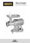
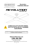
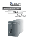
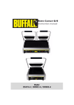
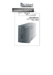
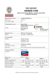
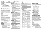
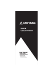
1
fluoresave A RESPONSIBLE USE OF POWER OWNER’S MANUAL English Version D092006 Models D12, D20, D32 fluoresave is a microprocessorcontrolled energy saving unit for fluorescent and other types of discharge lighting. Installation is simple and straightforward. NOTE: High Frequency fittings and those with electronic ballasts will not show energy savings. PRINCIPLE OF OPERATION The fluoresave design is based on the operation of fluorescent and some other types of gas discharge lights. When the lights are turned on, the fluoresave unit supplies mains voltage to the lights for ignition. After a short time period to ensure the stable operation of the lights, fluoresave switches to a lower energy saving voltage. The fluoresave continuously monitors the variation in the output of the current and the input mains voltage. Based on this information, the microprocessor switches the output voltage between the mains (input) voltage and the lower energy saving voltage. For example, when additional lights within the network are switched on, the fluoresave will switch back to main voltage for the ignition and wait for the current to stabilize before returning to the energy saving mode. Should mains supply voltage fall below 192V fluoresave, whether in Start or Energy Saving Mode, will switch back to mains voltage to ensure the normal operation of the lights. Furthermore, if a fault occurs in the energy saving circuit of the fluoresave, the microprocessor will ensure that the mains voltage is supplied to the lighting network. fluoresave is fitted with status indicator lights to indicate when the unit is in energy saving mode or to indicate any fault condition. A Responsible Use of Power English Version D092006 1 GENERAL SPECIFICATIONS A. Specifications Model Number Maximum Rating Maximum Load Maximum Current Unit Weight Dimensions Height Width Depth D12 12 Amp 2880 VA 12 Amp 7 Kg D20 20 Amp 4880 VA 20 Amp 8.5 Kg D32 32 Amp 7680 VA 32 Amp 12 Kg 350mm 190 mm 120 mm 350 mm 220 mm 120 mm 400 mm 260 mm 160 mm Warranty: 2 years (see page 9) B. Operation Conditions Environment: temperature: +5 to +45 deg C relative humidity: <75% Input Voltage: 230 – 240 Volts AC, 5060 Hz single phase with earth (energy saving mode will not operate below 198VAC). C. fluoresave models D12, D20 & D32 comply with the following CE Directives and Standards: CE 89/336/EEC ElectroMagnetic Compatibility Directive (Amended by 92/31/EEC & 93/68/EEC) EN500811:1992, EN500821:1998, EN6100032:2000, EN6100033:1995 73/23/EEC Low Voltage Equipment Directive (Amended by 93/68/EEC) BSEN50178:1998, BSEN61010:1:2001 German Standards: VDE Conformity with factory surveillance Reg Nr.A873 Australasian Standards: AS/NZS4O51, AS/NZS3100:2002, AS/NZS60335 INSTALLATION PROCEDURE IMPORTANT. Installation of the fluoresave unit does not require removal of the unit case cover. Fastenings of the top case cover of the unit are sealed. Do not open the unit case cover as this will void the warranty. There are no parts requiring service. **** The fluoresave unit should only be installed by a qualified electrician **** A Responsible Use of Power 2 English Version D092006 The Power supply to fluoresave should be single phase with Protective Earth. A switched fused Isolator or circuit breaker is required in the supply to the fluoresave. It is recommended that a fuse or MCB type C or D (type II or III) circuit breaker and wire for the supply/input side of the fluoresave unit should be selected for the maximum current that the model of fluoresave will allow. That is rating size 12 Amp or 20 Amp or 32 Amp. See model number on unit for rating size. The lighting manufacturers information on gas discharge lighting inrush current should be used to ascertain the correct fuse or circuit breaker and wire size of the output load. Due account should be taken of National Wiring Regulations, the environment and distance from the supply, in the calculation of acceptable wire size and type. If fluoresave is not mounted in a secure cabinet, a suitable cable restraining gland should be used. 1. Select the lighting circuit in which fluoresave is to be installed. fluoresave is specifically designed for use with magnetic ballast controlled fluorescent, sodium, mercury and metal halide lighting, however savings may be achieved with other forms of lighting also. 2. Ensure that the current loading of the circuit is within the maximum capacity of the fluoresave unit. Current loading of the circuit should be checked with a clip on ammeter. 3. fluoresave units should be installed in a dry dust free indoor environment with good ventilation, and mounted with a 50mm air space on each side. 4. fluoresave must be mounted in a vertical position on a wall or another insulated and flameretarding surface, with the cable entrance facing down. 5. To wire up the fluoresave unit, first remove the inspection cover (Figure 1. No: 5) from the front of the fluoresave unit. Inside there is a four position terminal block attached to the base plate (Figure 2). From left to right these terminals are: Live In (Active), Neutral, Live Out (Load), and Protective Earth, respectively. Cable entry is through the selected cable entry knockout hole (Figure 1. No: 7). Knock out either the 25mm or 32mm cable entry hole as required for conduit or trunking fittings or bush. Connect the respective wires to each of the four terminals, fasten the screws (Figure 2 No: 9). Refit the inspection cover onto the fluoresave unit. (Figure 1 No: 5) A Responsible Use of Power 3 English Version D092006 INSTALLATION PROCEDURE continued 6. Ensure that the connection is made correctly before turning on the power. 7. After switching on the power, the fluorescent tubes/lamps should ignite. At the same time the yellow indicating light on the fluoresave should be on. After approximately 8 minutes the fluoresave will change to Energy Saving Mode. This is accompanied by the turning on of the green indicating light and the switching off of the yellow indicating light. 8. The load current is the main operating parameter for the Fluoresave and the current and supply voltage relationship varies with the manufacturer’s type and age of the fluorescent tubes. It is important that the load current of the network should be kept below the maximum rating of the fluoresave. 9. If the fluorescent tube or lamp is replaced during the Energy Saving Mode, the newly replaced fluorescent tube or lamp may not ignite. To rectify this situation it may be necessary to switch the power to the lights off and on again. 10. The supply wiring must be adequate for the current capacity of the fluoresave unit selected for installation (see unit label for rating capacity). The fuse or breaker protection must also be adequate for the current rating of the fluoresave being installed. For further clarification of typical wiring of installations, see Figure 3. page 7 and Figure 4. page 8. 11. Voltage Reduction Selection Option: This fluoresave model comes factoryset to reduce the Voltage by 15% when in Energy Saving Mode, however when using fluoresave with other discharge lighting and older fluorescent tubes/lamps, better performance may be achieved by altering this Voltage Reduction to 12.5% or 10%. This simple alteration is made by changing the position of the ‘U’ shaped link in the secondary 4 position terminal block from H (15%) to M (12.5%) or L (10%) Voltage Reduction within the unit. This is accessed via the Inspection Cover for Cable Terminals, see Figure 1, and situated to the right of the main terminal block, see Figure 2. A Responsible Use of Power 4 English Version D092006 OPERATING GUIDE Operating conditions using the three indicator lights: INDICATOR Yellow on OPERATION CONDITION Power on, not yet entering energy saving mode. fluoresave will switch to energy saving mode in approximately 8 minutes. Green on In energy saving mode, fluoresave working properly. Input voltage on the low side, fluoresave is in energy saving mode. Current load is low (<1.5A). fluoresave switched to mains voltage, unable to switch to energy saving mode. fluoresave in energy saving mode, load current is low, will switch to mains voltage in 3 – 4 minutes. Low mains voltage and low load current, fluoresave switched to mains voltage, fluoresave function normal. Current exceeded maximum limit, fluoresave switched to mains voltage, fluoresave function normal. fluoresave faulty. Yellow flashing Yellow on, green flashing Green on, yellow flashing Yellow and green both flashing Yellow and red both on Red flashing, (yellow and green may also be on or flashing) No indicator light lit Fluorescent lights/lamps fail to start after power on Check supply fuses and circuit breakers. fluoresave faulty. 1. Faulty network circuit. 2. Faulty fluoresave. ACTION If unit fail to switch to energy saving mode, turn power off and on again. If fault persists notify supplier. Unit O.K. Unit O.K. Unit O.K. Unit O.K. Unit O.K. Reduce network loading and inspect possibility of short circuit. Restart fluoresave. If red light continues flashing, switch off fluoresave and notify supplier. Repair fuses. Reset circuit breakers. Notify supplier. 1. Check network circuit. 2. Notify supplier. A Responsible Use of Power 5 English Version D092006 Figure 1. Diagram of fluoresave Unit 1 2 3 5 4 7 8 6 1. fluoresave unit cover 2. Red indicator light 3. Green indicator light 4. Yellow indicator light 5. Inspection cover for cable terminals 6. Base plate 7. Cable entry via 25mm or 32mm cable entry knockout holes 8. Mounting holes 9. Terminal blocks (see Figure 2 below) 10. Energy Saving Selection Link Figure 2. Illustration of the terminal block 9 10 15% 12.5% 10% (H) (M) (L) Live In (Active) Neutral Protective Earth Live Out (Load) Supply Load 6 English Version D092006 Figure 3. Electrical Installation Diagram for fluoresave Unit Representative wiring diagram for single lighting circuit driven by one fluoresave unit, where the number of lights consume near the maximum capacity of unit. Fluorescent Tubes/Lamps Light Switches fluoresave unit Energy Saving Selection Link ° ° ° ° L N L PE (Supply) (Active) (Load) ° ° ° ° (H) (M) (L) 15% 12.5% 10% Fused/ Circuit Breaker Isolator L N PE Mains Supply A Responsible Use of Power 7 English Version D092006 Figure 4. Electrical Installation Diagram for fluoresave Unit Representative wiring diagram for multiple lighting circuits driven by one fluoresave unit, to take advantage of maximum use of capacity of unit and energy savings. Fluorescent Tubes/Lamps Light Switches Lighting circuit fuses/circuit breakers fluoresave unit Energy Saving Selection Link ° ° ° ° L N L PE (Supply) (Active) (Load) ° ° ° ° (H) (M) (L) 15% 12.5% 10% Fused/ Circuit Breaker Isolator L N PE Mains Supply N.B. Due to continuous product improvement fluoresave reserves the right to change the specifications and information above without notice. A Responsible Use of Power 8 English Version D092006 Fluoresave Limited MANUFACTURER’S WARRANTY Mo de el l N Nu um mb be er rs s M od D1 2, , D2 0, , D3 2 D 12 D 20 D 32 2 Y ea ar r F Fu ul ll l R Re ep pl la ac ce em me en nt t 2 Ye This Warranty applies to the above stated fluoresave products and is claimable against any failure or defect in operation by the products whereby that failure or defect or fault was caused due to reasons of faulty materials or workmanship. If the product is found to be defective within 24 months of the date of purchase by the end user, we or our authorized agent, will replace or repair the product at no cost to the user. Prior to the return of a product the user must contact the agent where the product was purchased and notify in writing the details of the fault, failure or defect. The manufacturer reserves the right to inspect all claims either at their own premises or that of the user. Fluoresave Limited does not extend any warranty or guarantee protection for: a) Product if not installed by a qualified electrician. b) Damage caused by incorrect installation. c) Damage caused by any party or other external force. d) Product where the fluoresave unit main case cover has been removed or altered. www.fluoresave.com A Responsible Use of Power 9 English Version D092006