1
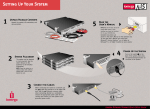
C O N N EC T I N G T H E W I R ES
STEPPING GAUGE
U S E R’S G UI D E
! NOTE
(No. 3)
SG- ET
EXHAUST TEMP
Thank you for purchasing our PIVOT STEPPING GAUGE SERIES.
Please read these instructions carefully before installing or using this meter.
1. For safety purposes, when working on your car always disconnect the − battery terminal.
(Reconnect to check for power.)
2. Make sure that all wire and snap connectors are firmly connected and insulated.
3. Be careful when laying wires not to cause any electrical shorts or wire breakage.
BASIC WIRING
Key Switch
ON
ON + 12V
FEATURES
To + 12V wire when
Small Lamp ON
3-pin coupler
●Microcomputer controlled stepping motor drive provides highly precise display of exhaust temperature.
Small Lamp
RE D ( I G N )
●Includes highly precise exhaust temperature sensor.
●One-touch hold peak function to view highest temperature.
ET
●Includes U-shaped brace and easy-to-install stand allows freedom in installation.
ORA NGE (Illumination)
●Easy-to-see LED white light means no bulb replacement. Includes brightness control function.
GND
B LA CK (Earth)
METER
【Opening Demo】By turning the key switch ON, the needle will move in a fixed pattern. (searching for the origin.)
2-pin coupler
CON TE N TS
RED
WHITE
Meter
Adjustable
Stand
U-shaped
Brace
GND
RED
WHITE
Exhaust Temperature Sensor
Connect
(wire crimps)
Exhaust
Temperature
Sensor
Fitting
Union B
Fitting
Bolt B
Knurled Nut
Allen
Wrench
■CONNECTION PROCEDURE
1. Connect the 3-pin Coupler Cable
① Properly connect each wire and cable.
3-pin Coupler 2-pin Coupler
Wire
Connectors×3
Cable
Cable
Hexagonal
Bolt
Hexagonal
Nut
Spring
Washer
Double-sided
User’s Guide
Tapes×3
ORANGE wire (Illumination)=Connect to the wiring that carries ( + 12V) when the Small Lamps are ON.
BLACK wire (GND)=Connect with the same screw in the steel panel that carries earth ground.
PART NAMES
<Front>
RED wire (IGN)=Connect to the wiring that carries ( + 12V) when key switch is ON.
② Connect the 3-pin coupler to the back of the meter.
Meter Indicator
●Display Range 2∼11.0(×100℃)
● White LED Illumination
・Linkage to Small Lamps
・Brightness Control Function
! NOTE
Connecting the 3-pin coupler to the water, oil, intake temperature gauge, or
speed meter will result in damage or a malfunction.
2. Connect the 2-pin Coupler Cable
① Make sure to properly connect the male end of the connectors to the female end of the connectors of the
exhaust temperature sensor being careful to match the cable colors.
② Connect the 2-pin coupler to the back of the meter.
Peak Switch
M ET ER I N S T A L L A T I O N
A. Installation with U-shaped Brace
<Rear>
Fasten from the back of
the instrument panel.
Bolt Hole
Fasten to a stable place with the
double-sided tape.
(On top of the steering column
cover or dashboard.)
When using the U-shaped brace, use this hole to fasten screw.
3-pin Coupler
1. Installing the Adjustable Stand
Connect to 3-pin coupler cable.
1. Fastening the Hexagonal Bolt for
Installing the U-shaped Brace
2-pin Coupler
Connect the 2-pin coupler cable for connecting to the exhaust
temperature sensor.
S WIT CH OPE R A T I O N S S E T T I N G S
Switch Press
Once
Peak Data
Display
Press for
more than
2 seconds
※ If the key switch is
O FF, the peak data
will be reset.
Will return automatically
after 2 seconds.
Inside the hole to the left is
a bolt lock; position the bolt
so as to lock.
Normal
Display
Small Lamp
OFF
While pressing
switch, Small
Lamps ON
Normal Display
Small Lamp O N
To Setting Mode
Meter light lit.
After the display
shows the peak
data, it will
return to the
normal display.
Hexagonal
Bolt
Hexagonal
Nut
Switch
Press
After about 2 seconds, the illumination will go
out for a moment and then come back on again.
Meter Brightness Settings
Brightness decreases
with each press
Bright
Dark
16 steps
By holding in, the brightness
will rapidly decrease and stop
at the darkest setting. By
pressing once after that, it will
return to the brightest setting.
2 . Installing the Meter
①Insert the meter into the front side of the
panel where you wish to install it.
②On the rear side, slide the U-shaped brace
onto the hexagonal bolt and securely fasten
with the spring washer and the knurled nut.
U-shaped Brace
Holder
Band
Hexagonal Bolt with Washer
2. Installing to the Car
①Carefully decide installation place.
②Bend the stand to securely fit the
place of installation.
③Clean the surface; removing all oil
or dust.
④Fasten using the double-sided
tape.
!
Doublesided Tape
Clean to
remove oil & dust
Please be sure about where you wish to install the meter, as
it is not advisable to reuse double-sided tape.
⑤After deciding the position and
angle of the meter face, fasten the
hexagonal bolts on both sides to
secure.
Hexagonal
Bolt
NOTE
If after installing the meter, the 3-pin coupler
cable is viewable and looks bad.
Panel, etc.
Spring
Washer
Knurled Nut
⇒
<If you wish to adjust several meters to match>
①Decide the brightness you wish to make the standard, check how many steps away that is from the brightest (or
darkest) setting.
②Adjust other meters to match the number of steps away from brightest (or darkest).
①Place the stand's holder band
around the back of the meter.
NOTE;
If you cannot get the band
around the meter, loosen the
hexagonal bolt and expand the
band.
②After getting the band in place, tighten the hexagonal bolt to
secure the band.
②With the bolt locked in
place, screw on the
hexagonal nut to tighten.
Will return automatically as it resets.
Meter Brightness Settings
Bolt Hole
①Insert the six-sided part
of the hexagonal bolt
into the hole at the back
of the case and slide it
to the left.
!
Peak Data Display and Reset
Normal
Display
B. Installation with the Adjustable Stand
Tie the 3-pin coupler cable behind the meter
with the zip tie.
zip tie
S E NS OR I N S T A L L A T I O N
BA SIC INS TAL L A TION
Make a
1/8 PT
tap hole
2-pin Coupler
Cable
Fitting Bo lt B
Exhaust
Manifold
1/8 PT
■INSTALLATION PROCEDURE
! INSTALLATION WARNING
1. When removing and installing the
exhaust manifold, please follow
directions for your type of model car.
2. Make sure to remove or install the
manifold only after allowing it to have
become fully cooled down; not doing
so may cause burns or injury.
(fig.A)
Connect
(wire crimps)
Fitting Union B
①Detach the exhaust manifold.
②After having decided the position from which to
measure the exhaust temperature, make a 1/8PT tap
hole.
③Fasten a fitting union B to the middle of the bolt.
(fig.A)
④Insert the tip of the exhaust sensor through the fitting
bolt B. (fig.B)
⑤Tighten the fitting bolt B on to the bolt so that the
tip of the sensor reaches to the middle of the inner
part of the exhaust manifold. (fig.C)
⑥Replace the exhaust manifold.
⑦After laying out the sensor cable, fasten the
connectors by colors to the cable connectors of the
2-pin coupler cable.
(fig.B)
Make a
1/8 PT
tap hole
Connected
to Meter
(fig.C)
Pass through so that
the screw side is
towards the tip.
Fitting Union B
Fitting Bolt B
!
Pass through so
that the narrow
end is towards
the tip.
Because the bolts are
tapered, be careful not
to screw them too
tightly as this may cause
damage.
TROUBLESHOOTING
Tighten the fitting
bolt B so that the tip
of the sensor reaches
to the middle of the
inner part of the
exhaust manifold.
※Please make the following checks before seeking repair.
Trouble
Possible Causes
Possible Solutions
The opening demo does not work
with key switched ON.
Contact failure of RED/BLACK wire.
Check the wire connections or
conditions.
Display dose not change.
●Contact failure of exhaust temperature
sensor.
●Contact failure of 2-pin coupler cable.
Check the sensor and wire
connections or conditions.
Even with the Small Lamps ON, the
meter light does not come on.
Contact failure of ORANGE wire.
The brightness is set at the darkest setting.
Check the ORANGE wire
connections or conditions.
Make any necessary change to
brightness.
The illumination color is
slightly different from other
meters.
This is due to a variance in the LED and is not a malfunction.
Please be aware that we cannot perfectly match the color.
The needle stops at the key
OFF position.
This is a characteristic of the stepping motor and is not a failure or
breakdown. If after the opening demo with the key ON (the engine
stopped), the exhaust temperature display reads correctly (under 200
℃ the display reads 200℃) the meter is working properly.
HOW TO USE THE WIRE CONNECTORS
1
※If soldering is possible, please do so.
2
Peel off about 10mm of the
vinyl cover at connection point.
3
Twist the uncovered wires.
※ Use a crushing tool to press the wire
connector. If you do not have such a
tool, use pliers or such to fold and
crush the connector together for a
Peel off about 10mm of the vinyl
secure contact.
cover at the end of the product’s wire.
※ After covering,
4
Close tightly with wire connector.
make sure to insulate
properly with vinyl tape.
PIVOT CORPORATI O N
87-3 OKADA SHIMO-OKADA MATSUMOTO-SHI NAGANO 390-0313 TEL0263-46-5901