1
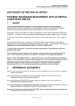
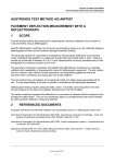
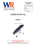
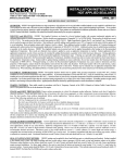
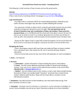
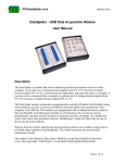
Mn/DOT Video-Log
User Manual
Report: MnDOT/OM-PM--2004-02
September 2004
Office of Materials
Pavement Management Unit
Table of Contents
Launching the Application ......................................................................................... 1
The Image Window ................................................................................................... 2
Changing the Brightness and/or Contrast ........................................................ 2
Zooming into the Image................................................................................... 5
The Image / Location Window ................................................................................... 7
Choosing Between Reference Post and True Miles......................................... 7
The Digitized Image Control Window ........................................................................ 7
Viewing the Images ......................................................................................... 8
Changing the Viewing Interval ......................................................................... 8
Changing Directions ........................................................................................ 9
Finding a Certain Location............................................................................... 9
Minimizing the Application ....................................................................................... 11
Closing the Application............................................................................................ 11
Making Suggestions for Improvements.................................................................... 11
User Manual for Mn/DOT Video-log System
Launching the Application
Assuming the software has been installed correctly on you PC, you should see an icon on your
desktop with a black crown in a red square as shown below:
Double click on the icon to launch the application. You will see a small rectangular box on the
screen saying:
“Pathview II Loading Road Section Records xxxx ”
Where: xxxx is the record number being loaded from the database. In the statewide database
there are approximately 27,000 records (approximately one per lane mile). In a district setup
there will be approximately 4,000 records to load.
Once the data is loaded, the application will open and the last location displayed by any
previous user will be shown. There are three windows in the application as shown below, the
Image window, the Image/Location window and the Digital Image Control window. Each
window can be resized and moved using the normal windows convention of dragging the mouse
from one of the sides or corners.
1. The Image Window
2. The Image / Location Window
3. The Digitized Image
Control Window
Example of video-log application windows.
1
The Image Window
The Image Window, as the name implies is where the images are shown. Normally both the
front and side images will be displayed together.
The Image Window
There is one menu item in the Image widow. By clicking on the Image in the upper left corner
will bring up the Brightness/Contrast controls. Mn/DOT’s system uses two images. Image 1 is
the front view while image 2 is the side view. Since these are the only two views we have,
clicking on the Brightness/Contrast for images 3-6 will do nothing.
Changing the Image Brightness and/or Contrast
The brightness and contrast can be changed using the Image menu in the Image window. The
settings will remain in effect until they are changed, even if the user exits the program. Clicking
the Image menu will bring up as shown below:
2
Once you click on one of the menu choices, the following screen will appear. The image
number will be displayed at the top of the box as shown below.
To increase the image Brightness: Click the “Bright +” box repeatedly
To decrease the image Brightness: Click the “Bright -“ box repeatedly
To increase the image Contrast:
To decrease the image Contrast:
Click the “Bright +” box repeatedly
Click the “Bright -“ box repeatedly
To restore the image brightness and contrast to its original settings, click on the
“Default” box.
3
The following two images show the result of clicking the “Bright +” button 20 times to increase
the Brightness.
Original Image 1
Image 1 after clicking “Bright +” 20 times
4
Zooming into the Image
The user can zoom into the image by holding the shift key down while using the mouse to draw
a box around the area of interest. Once the mouse button is released, the portion of the image
with the box around it will be magnified to the full screen.
Image before zooming in on speed limit sign
Image after zooming in on speed limit sign
5
In the image below, the bus stop is being zoomed in. Notice that after the zoom, the phone
number can easily be read. The zoom feature is useful for reading street signs, billboards and
other roadside appurtenances.
Image before zooming in on bus stop bench
Image after zooming in bus stop bench
TIP: To get the best zoomed image make the rectangle wider than it is tall and get the image as
close as possible before zooming in.
6
The Image / Location Data Window
The Image / Location data window shows the user information about the image(s) being
displayed. Information included in the window is the time stamp, record number, tape set
number (all used internally by the application to keep track of which images go with each record
in the database), distance from beginning of section, in feet, location of current image in either
true miles or reference post, latitude and longitude of image location, heading (in degrees),
district, beginning and ending Reference Post of section, beginning description, date tested,
International Roughness Index (IRI) and average rut depth in the left and right wheelpaths.
The exact information displayed on your PC depends on how the database was setup when it
was installed.
The Image / Location Window
Choosing Between Reference Post to True Miles
Users can change between having the location of the image shown in reference post of true
miles (miles form the beginning of the route, usually the state line) by clicking on the small grey
square to the right of the location. Clicking this box toggles between reference post (RP) and
true miles (TM)
The Digitized Image Control Window
The digitized image control window is used to choose images, change directions, change
locations and/or roadways and to play the movie. This is where you users will spend most of
their time while using the video-log application.
7
In the upper left corner, there are two small boxes with a 1 and a 2 in them. Clicking one of
these boxes will shut off the image with that number. Image 1 is the front view while image 2 is
the side view.
The Digitized Image Control Window
Viewing the Images
and
, are used to play the images. They can be used two ways,
The VCR buttons,
auto-play or manual. Pointing to one of the VCR buttons and clicking the right mouse button will
start auto-play, where the images advance automatically. To stop auto-play, simply click the left
mouse button while pointing to one of the VCR buttons. Holding the left mouse button down
will also activate auto-play, releasing it will stop the images. The most common way of using
the VCR buttons is manually. Each time the left mouse button is clicked the images will
advance by the distance in the Skip box. If the skip box is 0, the images will advance by the
default length. This is generally 25-feet in Metro and 50-feet outstate. The speed at which the
images scroll is directly related to the source of the images and the connection speed between
your PC and that source. If the images are stored on a district server, any district user will have
very quick rollover from one image to the next. If, on the other hand, a district user is accessing
the images from the central office server over the T1 line, the initial loading of the database and
the scrolling of the images will be much slower.
Changing the Viewing Interval
The “Skip” box is used to jump at longer intervals. For example, in the Metro area, images are
taken every 25-feet as the van drives down the road. If the area being studied does not need
such frequent images, the user can enter another value in the box. If the user enters 100 in the
8
box, the images will be displayed every 100-feet as the van drives down the road, skipping 3 out
of every 4 images. This gives the impression the vehicle is driving much faster than it is.
Changing Directions
The “Change Dir.” button changes the direction of travel. The next image displayed after
clicking this button should be very close to directly opposite the previous image but heading the
other way.
Finding a Certain Location
The “Find” button is used to choose another location on the same route or to pick another
roadway. Clicking on the find button will bring up the “Choose Location to Find” window. The
user must now choose a district, roadway, direction of travel and location. Once OK is clicked
the program will display the new image(s). The “Choose Location to Find” window shows the
locations in roughly one-mile sections. This is because in addition to video-log data, the data
collection van is collecting pavement roughness, cracking, rutting, etc. data on a mile-by-mile
basis. The user can choose to find a specific section by choosing one of the sections listed in
the window or enter a specific location if it occurs at someplace within one the sections.
The “Choose Location to Find” window lists the sections in both reference post and true miles.
The application will use either reference post or true miles, depending on the units displayed in
the Image / Location window.
For example, in the first image on the next page, the units in the Image / Location Data window
are set to reference post, as evidence by the 72.208 RP displayed in the second line. If the
user clicks on the section from RP 60.000 - 70.000 in the “Choose Location to Find” window,
69.000 appears in the “Enter Mile” box. When the user clicks OK the program finds the image
at that location and displays both the front and side images at that location. If the units in the
Image /Location Data window were true miles, then when the user clicked on the section from
RP 69.000 - 70.000, 69.012 would appear in the “enter Mile” box because that is the location of
the beginning of the section in true miles.
A user can also simply enter the location in the “Enter Mile” box to jump to a specific location.
Again, the value entered will be the same as the units in the Image / Location Data window,
either reference post or true miles. However, since the images are taken at intervals, you are
not able to go to every possible location. The program will show you the image taken closest to
the location you enter in the “Enter Mile” box.
9
Results of using “Find”
10
Minimizing the Application
To minimize the application, click on the minimize button in the upper right corner of the Image
window. You will have to minimize all other applications before you maximize the application
again, otherwise only the image window will be visible.
Closing the Application
To close the application, click on the “X” box in the “Digitized Image Control” window. This will
shut down the entire application. If you click on any of the other “x” boxes, in the Image and
Image / Location Data windows, you will have to also close the other windows separately.
Click here to close application
Making Suggestions for Improvements
User suggestions for improving the application are welcome. Suggestions should be sent to:
David Janisch
Pavement Management Engineer
Office of Materials, M.S. 645
1400 Gervais Avenue
Maplewood, MN 55109
(651) 779-5567
11