1
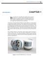
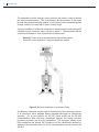
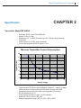
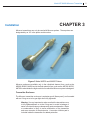
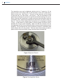
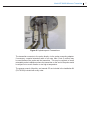
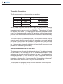
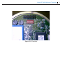
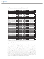
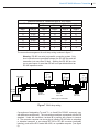
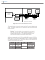
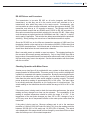
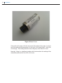
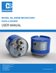
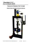
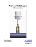
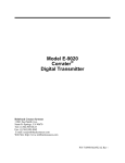
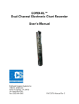
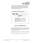
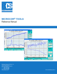
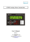
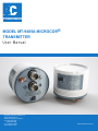
MODEL MT-9485A MICROCOR®
TRANSMITTER
User Manual
Rohrback Cosasco Systems, Inc.
11841 Smith Avenue
Santa Fe Springs, CA 90670
Tel: (562) 949-0123
(800) 635-6898
Fax: (562) 949-3065
www.cosasco.com
P/N:702200-Manualrev C
Microcor® is a registered trademark of Rohrback Cosasco Systems, Inc.
Windows® is a trademark of Microsoft Corporation.
No part of this manual may be reproduced or transmitted in any form or by any means,
electronic or mechanical, including photocopying and recording, for any purpose, without
the express written permission of Rohrback Cosasco Systems, Inc.
Model MT-9485A Microcor® Transmitter
Table of Contents
Chapter 1 Introduction ............................................................................1
Chapter 2 Specification ...........................................................................3
Chapter 3 Installation ..............................................................................5
Chapter 4 Operation ...............................................................................15
Appendix A Certifications ........................................................................19
i
ii
Table of Contents
Model MT-9485A Microcor® Transmitter
Introduction
CHAPTER 1
Note: Your Microcor® Transmitter was carefully tested, inspected
and packaged prior to shipment. Before unpacking the instruments,
please inspect the packaged materials for shipping damage and
retain damaged packaged materials to support any claim against
your freight carrier should this become necessary.
The Microcor transmitter Model MT-9485A is the latest Model of a new generation
of high-resolution digital instruments, which operate with special high-resolution
compatible electrical resistance probes. The resolution of the instrument is 18 Bit,
or 256 higher than standard electrical resistance measurement instruments. The
Model MT-9485A has an automatic gain feature that allows use on the full range of
Microcor probe types and alloys. The previous model MT-9485 requires specific
gain modules to match the probe type in use (see separate manual for Model MT9485).
This increased resolution of the Microcor system greatly improves response to
corrosion upsets, and at the same time allows measurements to be made in
virtually any environment. The patented technology combines speed of response
similar to linear polarization resistance with the universal applicability of electrical
resistance measurements.
Figure 1 Model MT-9485A Microcor Transmitter
1
2
Introduction
The transmitter must be relatively close-coupled to the probe in order to achieve
this improved performance. This is achieved by direct connection to the probe
through short probe-connecting adapter, or in the case of some retractable probes
through a cable of no more than 2 meters (6 feet) length.
A typical installation of a Microcor transmitter on a high pressure access fitting with
a flexible conduit connection cable is shown in figure 2. The transmitter and the
connectors that attach to it are explosion-proof (flame-proof).
Warning: Power must be removed before disconnecting either
connector on the transmitter if explosive gases are present
Figure 2 Microcor transmitter on an Access Fitting
The Microcor transmitter may be used for continuous on-line monitoring systems,
or in conjunction with a separate battery operated data-logger for autonomous
operation. For on-line systems, the 24 VDC power supply and the RS 485
communications allow multi-drop connections between the central corrosion
monitoring computer and all of the transmitters. This minimizes cabling costs.
Each transmitter has internal DIP switches to set the Identification Number or
Address of the transmitter from 0 to 31 for communications over the two-wire RS
485 bus.
Model MT-9485A Microcor® Transmitter
CHAPTER 2
Specification
Transmitter Model MT-9485A
• Enclosure NEMA 7 and IP 66/ NEMA 4X
• Weight 3.5 lbs (1.6 Kg)
• Dimensions 4.5” (115mm) Diameter by 4.25” (108 mm) High including
connectors
• Power supply 10-32 VDC at the transmitter
• Current consumption at 24VDC typical 17 mA
Microcor Transmitter Current Consumption
42
37
Typical Current
32
27
22
17
12
7
5
10
15
20
25
30
35
Supply voltage
• Communication RS 485 two-wire 2400 Baud, 8 data bits, 1 stop bit, no parity
(300 baud when connecting through RS232/485 converter MA-1000)
• Proprietary communications protocol (see Appendix B for details)
• RS 485 addresses 0 to 31
• Probe element resistance range: 1 to 50 milliohms
• Resolution 18 bit (1 part in 262,144)
• Ambient temperature range -40C to +70C (-40F to 158F)
3
4
Specification
• Hazardous area Certifications:
Europe (CENELEC)
CE 0539
II 2G
DEMKO 03 ATEX 0215219
STD EEx d IIC T6
Tamb= -40C to +70C
USA/Canada
Class 1 Zone 1A Exd IIC T6
Class 1, Div 2, Groups A, B, C, D
when installed in accordance with installation drawing 702106
Tamb= -40C to +70C
Model MT-9485A Microcor® Transmitter
CHAPTER 3
Installation
Microcor transmitters can only be used with Microcor probes. These probes are
designated by an “M” in the probe model number.
Figure 3 Model M4700 and M4500 Probes
Microcor probes are available only in the cylindrical element form, such as the
M2500, M3500, M4500 and in the flush element form, such as the M2700, M3700,
M4700 in order obtain the high resolution for which the Microcor system is designed.
Transmitter Enclosure
The Microcor transmitter enclosure is explosion-proof (flame-proof), and is sealed
with an O-ring so as to be gas-tight when fully tightened
Warning: It is very important to make sure that the transmitter cover
is fully tightened down on to the O-ring seal, to avoid in-leakage of
water or moist air that may subsequently cause condensation. Water
or condensation is likely to cause malfunction of the transmitter
and even corrosion of the electronics. A corrosion inhibitor pad is
included inside the transmitter for added protection.
5
6
Installation
The transmitter cover can be tightened, with the aid of a 2” center by 1/4” pin
spanner wrench on the base of the unit and by hand or with a 3/8” square bar or
similar on the cover. See Figure 4. The cover of the transmitter can be locked
in place with the 1/16” Allen screw. See Figure 5. This is a requirement of the
explosionproof (flameproof) enclosure to prevent accidental loosening of the cover.
When connecting the transmitter to a probe and power/communications cables in
a hazardous area, explosionproof (flameproof) connectors are used as shown in
Figure 6. Take care when making these connections not to damage the sealing
O rings. A small amount of white grease or silicone grease should be used to
lubricate the O rings to assist assembly. Make sure that the connector nuts are
fully tightened over the O rings, and that the Allen screws are then locked to prevent
loosening. The connections may only be made and unmade in a hazardous area
with the power shut off to the system. Take care when disconnecting a cable or
probe to make sure that the Allen locking screw has been loosened first.
Figure 4 Spanner Wrench
Figure 5 Locking Allen Screw
Model MT-9485A Microcor® Transmitter
Figure 6 Explosionproof Connections
The transmitter connects to the probe directly via the probe-connecting adapter.
If necessary, a special extension cable of no more than 6 feet (2 meters) may
be used between the probe and the transmitter. This may be required on some
retractable probe installations where the transmitter on the end of the probe would
be subject to too much vibration or too high a temperature.
The spanner wrench, Allen Key, and manual CD are included in the Installation Kit
(PN 702109) included with every order.
7
8
Installation
Transmitter Connections
The System connections to the transmitter are as follows:
Connector
A
B
Color
Black
Red
Pairs
Pair
Description
0 VDC Supply
24 VDC Supply
C
D
Green
White or Black
Pair
RS 485 - Tx+ (B)
RS 485 - Tx- (A)
When multiple transmitters are used on the same RS 485 line, each transmitter
must be set to a different electronic address. By the RS 485 standard, up to 32
transmitter/receivers may be used on one RS 485 line. The maximum line length
is 4000 feet (1200 meters). For lengths greater than 4000 ft, a repeater must be
used. For typical systems with more than 32 transmitters, multiple communication
ports are used on the corrosion computer with no more than 32 transmitters on any
one com port.
The requirements of the standards for use of the Microcor transmitter under its
explosion-proof rating (flame-proof) call for the transmitter to grounded (earthed)
or bonded to ground. When the transmitter is connected directly to a probe, this
bonding is accomplished through the probe body. To ensure good bonding, an 14
to 18 swg grounding wire can be attached to the transmitter at the grounding stud
provided and connected to ground (earth)
Setting Addresses for RS 485 Multi-drop
The transmitters are delivered with addresses already set. This address is marked
on the outside of the transmitter as the I/N or Identification Number. These
addresses can be used directly if the system is less than 32 transmitters without
making any changes. If it is an add-on to an existing system, then the number
may have to be changed, in order to avoid any address conflicts with an existing
transmitter on the same line. If there are more than 32 transmitters on the system,
then no more than 32 can be used on any one communication line.
The DIP switch for setting the address and other parameters is on the top circuit
board of the transmitter (see figure 6)
Model MT-9485A Microcor® Transmitter
Figure 6 DIP Switches
9
10
Installation
The Transmitter addresses are set by DIP switches 1 to 5
DIP
Address
ON
OFF
Address
ON
OFF
Address
ON
OFF
Address
ON
OFF
Address
ON
OFF
Address
ON
OFF
Address
ON
OFF
Address
ON
OFF
1 2 3 4 5 1 2 3 4 5
0
8
* * * * * * * *
*
*
1
9
* * * *
* *
*
*
*
*
2
10
*
* * * *
*
*
*
*
*
3
11
* * *
*
*
* *
* *
*
4
12
* *
* * * *
*
*
* *
5
13
*
* *
*
*
*
*
*
* *
6
14
*
* * *
*
* *
* * *
7
15
* *
*
* * *
* * * *
1 2 3 4 5 1
16
* * * *
*
*
17
* * *
*
* *
18
*
* *
*
*
*
19
* *
* *
* *
20
* *
*
*
*
*
21
*
*
*
*
* *
22
*
*
*
* *
*
23
*
* * *
* *
2 3 4
24
* *
*
25
* *
*
26
*
*
*
27
*
*
*
28
*
* *
29
*
* *
30
5
*
*
*
* *
31
*
*
*
*
*
*
*
*
*
The DIP switches 6 and 7 may be OFF or ON on this model.
System Wiring Requirements
Care is required when installing cabling for connection of an on-line multi-drop
system, especially on the 24VDC supply lines to ensure that there is sufficient
voltage at each transmitter to drive the electronics. A two pair individually shielded
cable is recommended. The gauge of the wire depends on the number of
transmitters and the maximum cable length. We do not recommend cables of less
than 22 swg. The following calculations are based on a nominal 24VDC supply at
the source. The Microcor transmitter and connectors are explosion-proof (flameproof) and meet hazardous area requirements. Flexible or rigid conduits are
required to meet North American hazardous area requirements. Flexible conduits
are also frequently preferred in order to provide physical protection to the cables,
such as shown in figure 2. If cabling is sized correctly for the 24 VDC supply, it will
also be more than adequate for the RS 485 communications.
Model MT-9485A Microcor® Transmitter
Maximum Number of Transmitters with 24 VDC Supply
Wire Gauge
Cable Length
300 m
600 m
900 m
AWG
Dia (in)
1000 ft
2000 ft
3000 ft
10
0.120
32
32
32
12
0.096
32
32
32
14
0.076
32
32
22
16
0.060
32
21
14
18
0.048
27
13
9
20
17
8
5
22
10
5
3
1200 m
4000 ft
32
27
17
10
6
4
2
The connection arrangement for multi-drop wiring is shown in figure 7.
Warning: RS 485 is a serial, not parallel, connection system. Only
short connections are permitted between the RS 485 bus and the
transmitter (not more than 50 feet). Splitting the RS 485 bus into
two or more spurs of more than 50 feet is not permitted without an
RS 485 repeater module.
Hazardous Area
Tx 1
A B D C
A B D C
Tx 3
0v
+24v
TxA
TxB
0v
+24v
+24v +0v
Tx 2
0v
+24v
TxA
TxB
DC Supply
TxA
TxB
Safe Area
A B D C
RS 485
Tx+ (A)
Tx- (B)
Corrosion
Computer
Junction
Box at TX 1
Junction
Box at TX 2
Junction
Box at TX 3
Multi-drop up to 32 transmitters
Figure 7 Multi-drop wiring
Conventions of designating Tx+ and Tx-, or A and B for RS 485, commonly vary
with different manufacturers. The conventions used here correspond with the EIA
standard. Under idle conditions, terminal B is positive with respect to terminal
A. The corrosion computer can use a plug-in isolating RS 485 card on a desktop
or industrial computer, or an external RS 232 to RS 485 converter (preferably
isolating), such as the RCS model MA-1000, on a portable computer (see figure
8).
11
Installation
Hazardous Area
Tx 1
0v
+24v
TxA
TxB
Tx 2
A B D C
Corrosion
Computer
RS 232
300
Baud
MA-1000
Conv
MP-9000-1
Power Supply
A B D C
RS 485
2400 Baud
24 VDC
Junction
Box at TX 1
TxA
TxB
Safe Area
0v
+24v
12
Junction
Box at TX 2
Multi-drop up to 32 Transmitters
Figure 8 Connection with RS232/485 Converter
The terminal blocks in the junction boxes should be 10 way with adjacent pairs
linked. This allows a single wire to be inserted into each terminal and provide
proper connection.
Warning: Two wires should not be connected into one terminal
block, as this may cause a high resistance connection or a
completely failed connection. This is important particularly in multidrop connection systems to avoid possible system failures.
On Microcor systems that use the RCS model MA-1000 converter for RS232 to
RS485, and or 24 VDC power supply Model MP-9000-1, completely assembled
RCS cables are generally used. Within these cables the same general color
coding of wires is generally used, namely
Connector
A
B
Color
Black
Red
Pairs
Pair
Description
0 VDC Supply
24 VDC Supply
C
D
Green
White or Black
Pair
RS 485 - Tx+ (B)
RS 485 - Tx- (A)
Model MT-9485A Microcor® Transmitter
RS 485 Drivers and Converters
The transmission is two-wire RS 485 on all units (computer and Microcor
transmitters), so that they are all in the receive mode until switched on for a
transmission, after which they return to the receive mode. Consequently, only
one transmitter at a time must be addressed, and then the response awaited. The
transmitter may take up to 1.5 seconds to respond. The Microcor and ICMS3/
Amulet software require that any RS485 cards, RS232 to RS 485 converters, or
fiber-optic converters have automatic switching for two-wire RS 485. When using
such converters set up the baud rate for 2400 baud, and 8 bit, 1 start bit, 1 stop bit,
and no parity if applicable. This sets the time delays associated with the automatic
switching. Wrong settings can cause loss of transmissions and their replies.
Since the RS 485 bus on the Microcor transmitter operates at 2400 baud, line
termination should not be required up to the maximum 4000 ft (1200 metres) that
the RS 485 standard allows. At this baud rate all reflections from the end of line
should have died before the next transmission character.
Bias is normally preset or settable on most converters. The standard settings for
the converter will normally operate satisfactorily. Only on long RS485 lines with a
large number of transmitters and if line termination resistors are used is it likely that
the bias setting may have to be adjusted. See the documentation with that comes
with the converter.
Checking Operation with Meter Prover
A meter prover (see figure 9) is provided with every system to allow testing of the
proper operation of the transmitter. This meter prover is very useful to distinguish if
a problem is suspected with a probe or transmitter. By simply connecting the meter
prover to the transmitter in place of the probe, you can demonstrate if everything
other than the probe and its cable and/or adapter is working correctly. The meter
prover produces a reading of approximately 50% of full scale. The exact value
is not usually particularly important, as it is usually more of a functional test. The
actual reading on the transmitter should be within the range of 46% to 54% of full
scale.
If the meter prover is being used to check the transmitter performance, the actual
reading and any changes over time can be reviewed. The repeatability of the
reading at constant temperature should be within the range of ± 0.2%. If the
temperature of the test probe changes say from 25C to 60C, changes of up to
±0.5% may occur due to temperature effects on the meter prover rather than the
transmitter.
If the probe is being read on Microcor software and is set to the maximum
resolution of 18 bits or 262,144 Probe Life Units (PLU), then the reading would be
between 120,586 (46% of full scale) and 141,558 (54% of fullscale). The actual
value displayed in this range should not then change by more than ±524 over time
when the meter prover is at constant temperature.
13
14
Installation
Figure 9 Meter Prover
If the probe with a span of 5 mils (such as an F10 probe) is being read in units of
mils, the reading should be between 2.3 mils (46% of full range) and 2.7 mils (54%
of full range). The reading should not then change by more than ±0.01 mils.
Normally, if there is a significant problem with the transmitter the reading will be
substantially different from the 50% of full scale.
Model MT-9485A Microcor® Transmitter
15
CHAPTER 4
Operation
The Microcor transmitter is normally used with a corrosion computer running
either Microcor software for simpler systems, or ICMS3/Amulet software for full
corrosion management systems. For detailed operation of this software refer to
the applicable manual.
The Microcor software has four programs as follows:
1. Micrec.exe - For direct on-line recording and display of readings from a single transmitter.
2. Micnet.exe - For direct reading and logging of data from multiple modules.
3. Miclog.exe - For transferring data from a data logger to the PC
4. Micret.exe - For displaying stored data files
The ICMS 3/ Amulet software allows continuous on-line monitoring and display
of multiple Microcor transmitters, typically up to 256 or more points. This is a full
corrosion management system.
With both systems, the reading interval may be set, typically at every 5 to 10
minutes. The probe span must be entered to display metal loss in mils, mm or μm.
The probe span is half of the probe element thickness.
Probe Designation
F4
F10
T10
Probe Thickness
4 mils
10 mils
10 mils
Probe Span
2 mils
5 mils
5 mils
The initial metal loss reading on a new probe will be near to zero. It may even be
slightly negative. As the probe corrodes the metal loss will increase in the positive
direction. Some noise will be apparent on the signal, and it will vary according to
the system in which the probes are operating. In stable temperature systems the
noise will be low, typically around 0.02% to 0.04% of probe span. In systems with
sudden temperature changes, such a 75C or similar, excursions up to 1% of span
may occur for a short while until the temperature and the probe stabilizes again.
When a probe reaches above around 80% of probe span, a replacement should
be made.
Even for a system with low corrosion rates, probes should be removed every 12
to 18 months to ensure that the probe element is clean and intact, and that no
penetration under the probe element to the reference has occurred.
16
Operation
Troubleshooting
If abnormal readings, or an excursion occurs that cannot be explained, the system
electronics may be verified by connecting the meter prover in place of the probe and
checking that the reading corresponds to 50% of the probe span. See “Checking
Operation with Meter Prover” in Chapter 3 Installation.
If the meter prover shows the electronics to be operating correctly, then inspect
the probe to transmitter connections, and the probe for damage, high resistance,
or poor connections.
After initial application of power, the transmitter takes approximately one minute to start up
during which time it will send the error code -999,999, or -999,996 when its data is requested.
On ICMS3 systems these codes will show up as an error message.
-999,999 - “Startup Mode”.
-999,996 - “Auto Ranging”
If there is a probe or probe connection failure an error code -999,998 or -999,997 will
be generated. On ICMS3 systems this will display as follows:
Code: -999,998 Display: Probe Fault (4)
Code: -999,997 Display: Probe Fault (1)
Frequently Asked Questions
Why is the Metal Loss showing negative on a new probe?
The nominal range of the probe is zero to the probe span, such as zero to 5 mils.
However, the value on a new probe is zero ± 7.5%. This means that the initial
value can be slightly negative. As the probe corrodes it moves in the positive
direction and shows positive metal loss values.
Why is the Corrosion Rate showing negative?
There is always some noise on the metal loss measurement. Corrosion rate is
computed from the metal loss data by linear regression(that is the slope of the
best straight line through the data used in the regression period) over typically
12 to 48 hours. At low or zero corrosion rates, this small amount of noise may at
times produce small negative corrosion rate values. If significant corrosion occurs,
this small noise effect will not be noticeable. It is possible to block this negative
reading or noise but this can slow down the response to a real corrosion upset
when it occurs. Consequently, the greater sensitivity is preferred even if it allows
occasional negative corrosion rates, which obviously are not true values. If the
negative values are blocked as false values, it can bias calculations on long term
low corrosion rates.
Model MT-9485A Microcor® Transmitter
How do we know when a probe should be replaced?
The probe reading of metal loss will commence near zero (±7.5% of span) and will
increase as corrosion occurs. When the metal loss reading gets near to 80 to
90% the probe span, it should be replaced. Even if the probe span has not been
reached, it is preferable to replace the probe after two years of operation.
17
18
Operation
Model MT-9485A Microco® Transmitter
ATEX Certification
19
Appendix A
20 ATEX Certification
Model MT-9485A Microcor® Transmitter
21
22 ATEX Certification
Model MT-9485A Microcor® Transmitter
23